Article

Investigation of Scale Conversion for Inductive Power Transfer in Series-Series Configuration

School of Electrical Engineering, University of Ulsan, Ulsan 44610, Korea
*
Author to whom correspondence should be addressed.
Electronics 2020, 9(11), 1851; https://doi.org/10.3390/electronics9111851
Submission received: 2 October 2020 / Revised: 28 October 2020 / Accepted: 2 November 2020 / Published: 5 November 2020
(This article belongs to the Special Issue State-of-the-art Power Electronics in Korea)

Abstract

:
Nowadays, inductive wireless power transfer is widely used in various applications over a large power range. However, for high power systems, testing the magnetic coupler implementation often requires too much time, space, and expense for normal laboratory conditions. For such a reason, a miniaturized system is a viable alternative to the actual system for a preliminary test of transfer characteristics and control strategy before constructing the full-scaled system. This paper studies the scale conversion rules required for miniaturized coupler design to ensure the scaled and original systems are as equivalent as possible to each other in terms of transfer characteristics. To verify the proposed theory, a 1:15 scaled magnetic coupler was constructed, and its transfer characteristics were compared with the original system. The proposed scaling rules were tested by experiment, and the results agree well with the theoretical analysis and simulation.

1. Introduction

Inductive wireless transfer (IPT) is one of the most promising solutions for wireless power transmission. Since the paper from Soljacic at MIT was published [1], this technology has received more attention from researchers. At present, it has been widely used in various power applications from mega-watt to milli-watt systems such as cranes, electric vehicles, micro-robots, and biomedical systems [2,3,4,5]. IPT system has a low maintenance cost, high system reliability, and high-efficiency [6,7].
Nowadays, the research focuses on many issues in IPT, and the major research topics can be categorized into coil design, compensation network, and power flow control. First, coil design is essential to increase the output power by enhancing the coupling coefficient [8]. In addition, various coil shapes and configuration have been investigated such as circular coil [9], cylinder-shaped [10], dual-transmitter structure [11], and three-coil structure [12,13,14]. Second, the compensation network is investigated to make up for the inductance of the coil [15]. Third, power flow control has been used for achieving the maximum efficiency [16], zero voltage switching [17], and low standby power consumption [18]. Every research topic above requires a lot of time for the implementation of energy coupler coils in actual size.
Therefore, if the predicting characteristics of IPT systems from the miniaturized system is investigated, it will be greatly useful to save time, space, and labor before full-scale implementation. Scale conversion technique refers to scaling of the physical size of the system. However, the characteristic should be kept equivalent during the scaling procedure. The scaling conversion has been used in many applications. Including the maglev system developed at MIT, which is constructed with a 1/25 scale of the actual system [19], different kinds of scaling rules have been proposed in various applications such as motor [20,21], transformer [22], and power converter [23,24,25,26].
Recently, the authors of [27,28,29] presented scaling rules for IPT. In [27], a scaling down rule is proposed. However, since the resonant frequency is kept constant and the change of parasitic resistance is not considered, this rule is able to be applied in only a small scaling range of around 0.5, which should be larger in the practical case. In [28], the authors investigated the scaling law based on the relationship between the coupling coefficient and coil size for maximum efficiency. However, they assumed the quality factor of the coil is considered as the constant even with different size of coil. In fact, the time constant of the inductance to parasitic resistance is dependent on the coil size; it is difficult to maintain the quality factor to be constant during the scaling. Some researchers tried to introduce the normalized distance concept to describe the IPT coil characteristic in similar shapes with different sizes [29]. However, they observed the efficiency change concerning the normalized distance. Therefore, this study is not so useful for preserving the characteristics between the scaled and the original system. All of the above-mentioned papers only consider the geometric scale factor without considering the change in the parasitic resistance during the scaling process. However, in the real system, it is difficult to keep parasitic resistance scale-invariant. In addition, the IPT system normally works as a voltage converter; thus, voltage gain should be considered as an important parameter of the system. Nevertheless, the authors of [27,28,29] did not consider the voltage gain. Besides, the authors of [28,29] only considered constant frequency assumption. However, frequency control being widely applied in IPT to regulate the output voltage and power as shown in [30,31,32,33,34]. Therefore, the transfer characteristics of the magnetic coupler should also be considered in variable frequency conditions.
Recent publications present little investigation on retaining equivalence during scale conversion in terms of the overall transfer characteristics. Specifically, the two key factors, efficiency and voltage gain, have not been studied so far. Thus, we propose a novel scaling conversion rule to resolve the problems of achieving an effective miniaturization in IPT system. There are three clear objectives. First, a scaling rule that considers frequency domain is investigated. Second, it considers parasitic resistance change. Third, the efficiency and voltage gain of IPT system are simultaneously considered in scaling procedure. Among various compensation topologies in IPT system, the series–series (S-S) compensation network is the most popular in high power system [35,36,37]. Therefore, S-S compensation network is considered in this paper, and the circular coil shape [38] is chosen for the analysis because of its simplicity in the mathematical formulation. With some modification, the proposed method can be adaptable for other compensation networks with different coil shapes.
The paper is organized as follows. In Section 2, the target system and performance indices are defined and scaling factor formulation is presented. Eventually, the scale conversion rule to retain the performance is proposed. The proposed scaling law is verified with a hardware prototype in Section 3. The conclusion is made in Section 4.

2. Materials and Methods

2.1. Target System and Performance Indices

In the IPT, two important factors of system are the voltage gain and efficiency, those parameters are chosen as key parameters in the proposed scaling rules. The S-S compensated system in Figure 1a is the systems considered in this paper because of its popularity in high power applications. L 1 and L 2 are transmitter and receiver coil inductances, and C 1 and C 2 are the compensation capacitance of transmitter and receiver coils for reducing the VA of the coils. Moreover, R 1 and R 2 are the parasitic resistances of the transmitter and receiver coils, respectively. The ac source, V 1 , is usually generated from a full-bridge inverter. For simplicity, only identical magnetic couplers are assumed here, and thus every circuit parameter, including the resonant frequency, is regarded as equal. That is, L = L 1 = L 2 , C = C 1 = C 2 , and R = R 1 = R 2 , and so are the quality factors for the coupler, Q = ω 0 L R = ω 0 L 1 R 1 = ω 0 L 2 R 2 . When the coils are coupled by the coupling coefficient, k, and the secondary side is terminated by the load resistance, R L , two normalized coupler design parameters can be introduced as F O M = k Q and r d = R L R . FOM (figure of merit) is the product of coupling coefficient, k, and the quality factor, Q, which is a measure for the effectiveness of the resonance. Those are known as key factors in the design of the wireless power transfer system. The ratio of the load resistance to the parasitic resistance of the coupler is defined as r d . It is well known that the voltage gain, M V , A C , and power transfer efficiency, η , of the S-S compensated coupler in Figure 1a at the resonant frequency are completely characterized by the following two equations [39], the detailed derivation of which is given in Appendix A.
M V , A C = V 2 V 1 = F O M r d F O M 2 + ( 1 + r d ) ,
η = F O M 2 · r d ( 1 + r d ) 2 + F O M 2 ( 1 + r d ) .
Therefore, the efficiency and the voltage gain can be kept constant by making sure F O M and r d are invariant during the scaling process and the way to achieve such a condition is discussed in the subsequent sections.

2.2. Proposed Scaling Rules

2.2.1. Geometric Scaling and Circuit Parameters

Figure 1b shows the magnetic coupler structure under consideration, where two circular coils with square cross-section are separated by a distance, z. The inductance of a coil can be approximated by Stefan’s formula [40,41],
L = 0.1 a N 2 S ( a , b ) ,
where N is the number of turns and
S ( a , b ) = 4 π 1 2 1 + 1 6 b 2 a 2 ln 8 b 2 a 2 0.84834 + 0.2041 b 2 a 2 ,
where a is the mean radius of the turns and b is the radial dimension of the cross-section of coil.
When the geometric ratio of the coil structure is preserved as
a a = b b = z z = γ g ( < 1 ) ,
during the scaling process, S ( b , a ) is invariant so the inductance is also scaled by the above geometric scale ratio, γ g . It should be noted that every primed variable in this paper denotes the scaled quantity of the non-primed variable. Therefore, the following inductance relations are obtained.
L L = γ g
Remember that, to keep voltage gain and the efficiency at the resonant frequency the same as the original system, both F O M = k Q and r d = R L R should be scale-invariant. It is expected that F O M can be kept practically invariant if the effect of an inductance change caused by the geometric scaling is wholly canceled out by the parasitic resistance change. However, even though the self and mutual inductance are scaled by the same factor as the geometric scaling, it is difficult to accurately estimate the parasitic resistance of the coupler in most practical cases because of the discrete Litz-wire availability and the field distribution due to factors such as skin and proximity effects [42]. In addition, it is not uncommon for the ac resistance, R A C , to be much higher than the dc resistance, R D C , which makes any lumped approximation almost always underestimate the resistance, R. The DC resistance can be approximately calculated as
R D C = 2 π a b 2 σ
where σ is the conductance of the conductive material and the R A C of Litz-wire can be given by Dowells equation [43].
Thus, it is necessary to compensate more finely for the result after deciding the scale conversion ratio. At first, we need to obtain the ratio between the two parasitic resistances,
R R = γ r ,
either by calculation from field simulation software or by measurement of the miniaturized hardware. According to resistance ratio, we must compensate for the change in resistance and inductance in order to keep the quality factor, Q, invariant over the scaling conversion. We propose two methods of compensation: The first method is to adjust the coupling coefficient to the ratio given by
k k = γ k ,
which could be achieved by additional adjustment of the coil distance in the scaled system. The second method is to introduce resonant frequency scaling by a factor of
f 0 f 0 = γ f .
Depending on the actual system, either or both of these two methods could be applied. However, the first method without resonant frequency scaling is recommended in most cases, because the resonant frequency is invariant during the scaling process. The advantage is that, in terms of controller design, the results from the scaled system can be directly applied to the original system with only a few modification. On the other hand, if the coupling coefficient scaling by coil distance adjustment is sometimes not enough to completely compensate the quality factor, frequency scaling can be used together with the coupling coefficient scaling. Likewise, to make r d scaling-invariant too, it is necessary to counter-scale it by the load resistance scaling as in the following.
R L R L = γ r
As a result, to make both F O M and r d invariant at the same time, the following condition should be met:
γ k γ f = γ r γ g .
Condition (12) requires design trade-offs that, to some extent, consider the physical situation. As the loaded quality factor, Q L = F O M k ( 1 + r d ) is inversely proportional to the coupling coefficient, compensation by adjustment of the coupling coefficient ratio, γ k , will modify the bandwidth of the frequency response. For example, if we put a high priority on keeping the resonant frequency the same during the scaling process, it is inevitable that we allow bandwidth widening or narrowing. On the contrary, if we choose to keep the coupling coefficient the same as the original system, a resonant frequency shift occurs. Since the coupling factor should be limited to less than unity and the appropriate resonant frequency for the driving circuit technology should be considered, various combinations of γ k and γ f can be tried according to the real world situation.
The scaling process is completed by choosing the compensation capacitance using
C C = 1 γ f 2 γ g
to meet the resonant condition. According to the input driving voltage, V 1 , the output power is scaled by
P o u t P o u t = V 1 V 1 2 1 γ k γ f γ g ,
where P o u t is the system output power delivered to the load resistance at the resonant frequency (since the voltage gain is invariant).
In this paper, only symmetric structure is considered for simplicity; however, our work could be extended to other structure. If the transmitter coil and receiver coil are in different shape, size or number of turns, the formula of efficiency and voltage gain of the proposed scaling rules should be reformulated and different inductance formula should be applied; however, the procedure of scaling rules can be applied in the similar manner to retain the transfer characteristic during scaling process.

2.2.2. Design Procedure for the Proposed Scale Conversion

Following the scaling rules presented in the previous section, the design procedure is presented here and a flowchart for the proposed scale conversion is shown in Figure 2. Assuming that the original system design parameters including coil geometry and parasitic resistance are given, F O M and r d can be calculated, and then voltage gain and efficiency can be obtained using (1) and (2). The geometric scale factor, γ g , is decided first, the physical dimension of the scaled coil is given by (5), this will be used for the construction of the scaled system. The parasitic resistance ratio in (8) can be obtained either by field simulation software or by real measurements from the physical implementation of the scaled coil. Through compensation either by the coupling coefficient, γ k , or by frequency scaling, γ f , condition (12) should be met to keep the efficiency and voltage gain of the original and scaled systems similar. In this compensation step, various combinations can be tried, but it should be noted that the coupling coefficient, k , needs to be less than unity and the frequency of operation should be confined within the allowable band. Otherwise, the design step should be returned to try a different compensation scenario or another physical ratio to meet such physical limitations. In the final stage, the compensation capacitor for the scaled system is set out by Equation (13).

3. Prototype Design and Experimental Results

3.1. Prototype Design

For verification of the proposed method, firstly, the original coupler and its miniaturized version with a geometric scale of γ g = 1 15 were simulated in the ANSYS-Maxwell software, as shown in Figure 3. The original coil has a = 15 cm, b = 1.2 cm, and N = 34 (Litz-wire with 500 strands of 0.1 mm diameter), while the scaled coil has a’ = 1.1 cm, b’ = 0.1 cm, and N = 34 (Litz-wire with 200 strands of 0.06 mm diameter). In addition, the copper is used as conductive material. The 2D-RZ Litz bundle model in ANSYS-Maxwell is adopted, where losses are calculated with AC power loss estimations in [44,45]. In this simulation, R A C is calculated from the total AC loss that includes skin effect and proximity effect. The value of AC resistance of the original and scaled system are 360 and 89 m Ω , respectively. Next, a prototype scaled coil was implemented with the parameter as the same with the simulation, as shown in Figure 4. The coil parameter was measured by an Agilent 4363B LCR meter. Theoretical calculations using the lumped inductance formula in (3) were compared with the experimental results; as shown in Table 1, the coil resistances obtained were R = 352 m Ω and R’=115 m Ω by measurement, which gives γ r = 0.327 .
Consider a S-S compensated resonant coupler system under load with F O M = 39 and r d = 100 in an F O M r d design plane; all circuit parameters for the original and the scaled system are shown in the left column of Table 1. These values were verified by actual measurements on the scaled coil, as shown in the right column of Table 1. I To retain the voltage gain and efficiency after the scaling process, only the coupling coefficient is adjusted by γ k = 5.16 , while the resonant frequency is kept as before, i.e. γ f = 1 , to obey the conversion rules suggested in Section 2. This kind of coupling coefficient compensation is easily achieved by further reducing the distance between the transmitter and the receiver coils from z’ = 2 cm to z’ = 0.4 cm, which increases the coupling coefficient from 0.06 to 0.31.

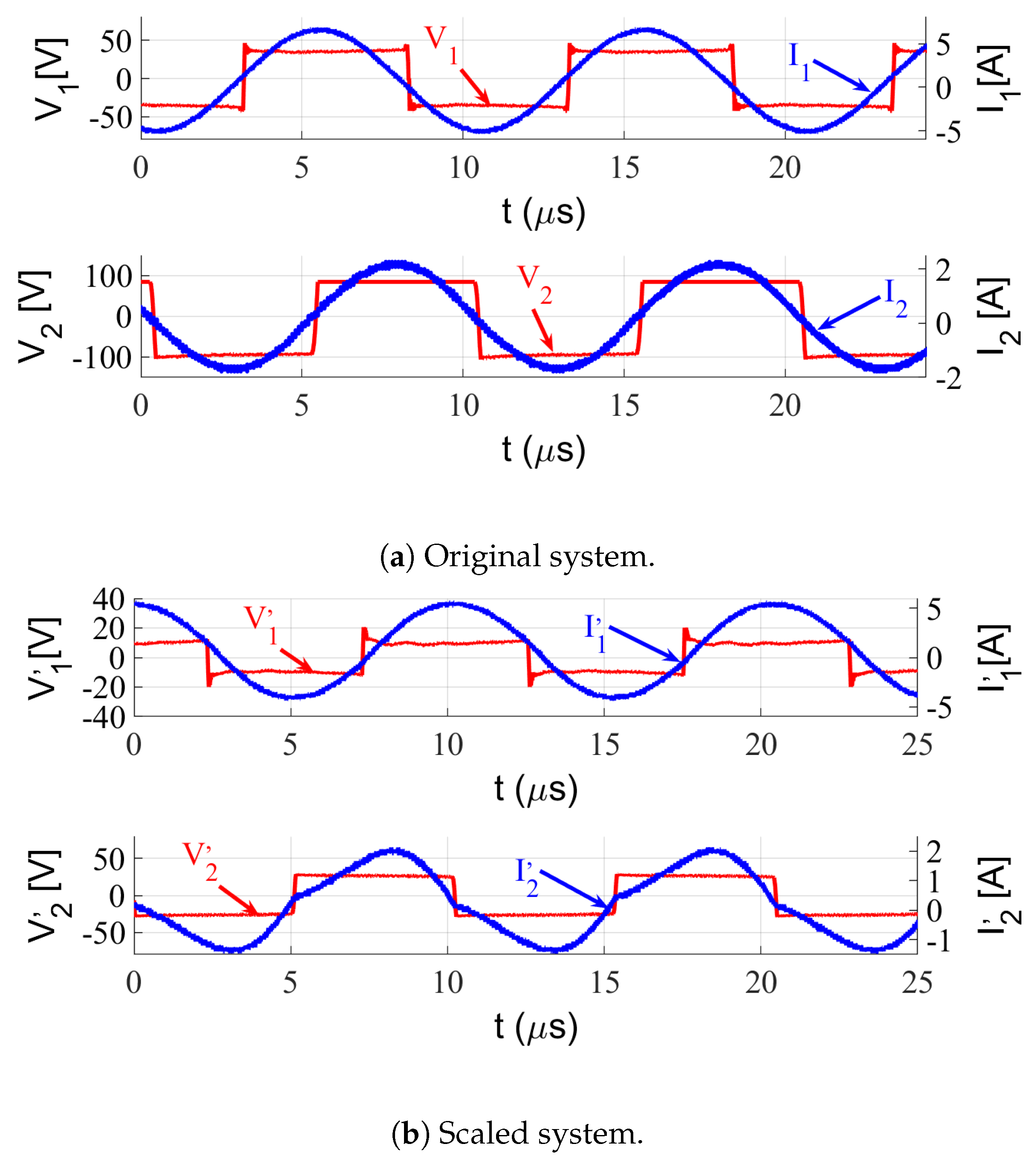
3.2. Experimental Results

To verify the prototype design, a full-bridge inverter and a full-wave rectifier are appended to the transmitter and receiver coils, respectively, as shown in Figure 5; the four switches are used to generate ac voltage, V 1 , from dc input voltage source, V s . The output voltage of the receiver side, V 2 , is connected with a full-wave rectifier; thus, the equivalent ac resistive load, R L , was replaced by a resistive load, R o , with a scale factor of 8 π 2 [46,47]. The original and scaled system operate at 100 kHz. The experimental setup is shown in Figure 6 and the parameters for both the original and the scaled system are presented in Table 2. At first, a sequence of signal-level tests using a network analyzer (AP300) were performed to extract the frequency response of the ac voltage gain. Then, a power-level test using a power analyzer (PPA 5530, N4L) was performed to find the efficiency as well as the dc voltage gain. Figure 7 plots the voltage gain in the frequency domain. The data from the experiment (red dots), the simulation (solid blue line), and calculations (black star) for the original system are shown in Figure 7a,b these results are all very similar. The results from the scaled system are shown in Figure 7c,d, and they show only slight differences in the voltage gain. The error is partially because discrete coil availability caused a small deviation in the inductance value of the simulation; other factors that affect the discrepancies are an increased stray capacitance and a reduced loaded quality factor. Further, the reduced coil distance introduced in the scaled system during the coupling coefficient scaling increases stray capacitance between two coils. As explained below, the inherent bandwidth widening in the voltage gain curve causes the waveform distortion in the current and makes the calculation based on fundamental harmonic assumption prone to error.
The input and output waveforms of the original and the scaled systems from the power-level tests are depicted in Figure 8. The voltage amplitudes of the original system, V 1 and V 2 , are 35.2 and 96.1 V, as shown in Figure 8a; therefore, the voltage gain is measured as 2.73 . Figure 8b shows the waveforms for the scaled system, where the voltage gain measured is 2.7 . The voltage gain measured in the experiment is slightly higher than the theoretical value because of the diode voltage drop. The results show that the scaled system preserves the voltage gain and efficiency, only allowing widened bandwidth of about three times, as expected from the theory. It should be noted that it is possible to reduce this bandwidth widening by choosing different combinations of γ k and γ f compensation.

4. Conclusions

This paper presents scale conversion rules for the IPT system with identical S-S structures. The proposed scaling rules have outstanding merits when compared with existing scaling rules. In terms of magnetic coupler characteristics in the frequency domain, the voltage gain and the power transfer efficiency can be retained with a minimized distortion in the curve shape. In addition, two viable methods are presented to compensate the parasitic resistance change considering practical situations. By applying the proposed scaling rule, we can build a miniaturization system prior to a large full-scale IPT system. Because most of the characteristics such as voltage gain and efficiency are maximally retained, overall circuit operation and control strategy can be tested with saved time, space, and labor.
For verification, a 1:15 scale miniaturized coil was designed and implemented; its characteristics were compared to the original system. The results of our theoretical analysis match well with the simulation and experiment. In this study, only symmetric structures were considered for simplicity; however, our work with slight modification could be extended to other configurations as well. In addition, the non-identical coil structure is commonly used in some application, the proposed scaling rule can be improved to include non-identical coil structure in the future. The proposed scale conversion technique is expected to be very useful in the construction of miniaturized systems allowing researchers to test system before committing to produce full-scale models.

Author Contributions

S.-J.C. proposed the basic concept of this paper; and C.-T.T. contributed the mathematical formulation and hardware implementation. All authors have read and agreed to the published version of the manuscript.

Funding

This work was supported by the 2019 Research Fund of University of Ulsan, Korea.

Conflicts of Interest

The authors declare no conflict of interest.

Appendix A. Derivation of Performance Indices

The coupler equation of S-S configuration in Figure 1a can be simplified as
V 1 / R 0 = 1 j k Q j k Q 1 + r d 1 I 1 I 2 .
Therefore, Rx and Tx currents are obtained as
I 1 = V 1 R 1 + r d k 2 Q 2 + 1 + r d ,
I 2 = j V 1 R k Q k 2 Q 2 + 1 + r d .
Thus, the output power is given by
P o u t = 1 2 R L I 2 2 = 1 2 V 1 2 R L k 2 Q 2 r d 2 [ k 2 Q 2 + ( 1 + r d ) ] 2
and the ac voltage gain formula can be obtained as follows
M V , A C = 2 R L P o u t V 1 = F O M · r d F O M 2 + ( 1 + r d ) .
Furthermore, the power efficiency is given by
η = P o u t P i n = R L I 2 2 R I 1 2 + I 2 2 + R L I 2 2 = F O M 2 · r d ( 1 + r d ) 2 + F O M 2 ( 1 + r d ) .

References

  1. Kurs, A.; Karalis, A.; Moffatt, R.; Joannopoulos, J.D.; Fisher, P.; Soljačić, M. Wireless power transfer via strongly coupled magnetic resonances. Science 2007, 317, 83–86. [Google Scholar] [CrossRef] [Green Version]
  2. Covic, G.A.; Boys, J.T. Inductive power transfer. Proc. IEEE 2013, 101, 1276–1289. [Google Scholar] [CrossRef]
  3. Guidi, G.; Suul, J.A.; Jenset, F.; Sorfonn, I. Wireless Charging for Ships: High-Power Inductive Charging for Battery Electric and Plug-In Hybrid Vessels. IEEE Electrif. Mag. 2017, 5, 22–32. [Google Scholar] [CrossRef]
  4. Gao, J. Inductive power transmission for untethered micro-robots. In Proceedings of the 31st Annual Conference of IEEE Industrial Electronics Society, IECON 2005, Raleigh, NC, USA, 6–10 November 2005; p. 6. [Google Scholar]
  5. Foote, A.; Onar, O.C. A review of high-power wireless power transfer. In Proceedings of the 2017 IEEE Transportation Electrification Conference and Expo (ITEC), Chicago, IL, USA, 22–24 June 2017; pp. 234–240. [Google Scholar]
  6. Bosshard, R.; Kolar, J.W. Multi-Objective Optimization of 50 kW/85 kHz IPT System for Public Transport. IEEE J. Emerg. Sel. Top. Power Electron. 2016, 4, 1370–1382. [Google Scholar] [CrossRef]
  7. Bosshard, R.; Iruretagoyena, U.; Kolar, J.W. Comprehensive Evaluation of Rectangular and Double-D Coil Geometry for 50 kW/85 kHz IPT System. IEEE J. Emerg. Sel. Top. Power Electron. 2016, 4, 1406–1415. [Google Scholar] [CrossRef]
  8. Zaheer, A.; Hao, H.; Covic, G.A.; Kacprzak, D. Investigation of Multiple Decoupled Coil Primary Pad Topologies in Lumped IPT Systems for Interoperable Electric Vehicle Charging. IEEE Trans. Power Electron. 2015, 30, 1937–1955. [Google Scholar] [CrossRef]
  9. Budhia, M.; Covic, G.A.; Boys, J.T. Design and Optimization of Circular Magnetic Structures for Lumped Inductive Power Transfer Systems. IEEE Trans. Power Electron. 2011, 26, 3096–3108. [Google Scholar] [CrossRef]
  10. Chen, X.; Fu, X.; Jiang, C.; Pei, C.; Liu, F. Magnetic-field-model and circuit-model based analysis of three-phase magnetically coupled resonant wireless power transfer systems with cylinder-shaped coils. J. Power Electron. 2018, 18, 1154–1164. [Google Scholar]
  11. Zhu, G.; Gao, D.; Lin, S. Leakage Magnetic Field Suppression Using Dual-Transmitter Topology in EV Wireless Charging. J. Power Electron. 2019, 19, 625–636. [Google Scholar]
  12. Chen, X.; Chen, L.; Ye, W.; Zhang, W. Three-coil magnetically coupled resonant wireless power transfer system with adjustable-position intermediate coil for stable transmission characteristics. J. Power Electron. 2019, 19, 211–219. [Google Scholar]
  13. Meng, Y.; Wang, Z.; Jiang, P.; Wang, W.; Chen, F.; Yan, G. Optimization and analysis of Helmholtz-like three-coil wireless power transfer system applied in gastrointestinal robots. J. Power Electron. 2020, 20, 1088–1098. [Google Scholar] [CrossRef]
  14. Zhu, G.; Gao, D. Highly effective leakage magnetic field suppression by using a reactive coil in perfectly aligned EV wireless charging systems. J. Power Electron. 2020, 20, 11–21. [Google Scholar] [CrossRef]
  15. Wang, C.-S.; Stielau, O.H.; Covic, G.A. Design considerations for a contactless electric vehicle battery charger. IEEE Trans. Ind. Electron. 2005, 52, 1308–1314. [Google Scholar] [CrossRef]
  16. Zhong, W.X.; Hui, S.Y.R. Maximum Energy Efficiency Tracking for Wireless Power Transfer Systems. IEEE Trans. Power Electron. 2015, 30, 4025–4034. [Google Scholar] [CrossRef] [Green Version]
  17. Chen, C.; Zhou, H.; Deng, Q.; Hu, W.; Yu, Y.; Lu, X.; Lai, J. Modeling and Design of Zero-Voltage-Switching Controller for Wireless Power Transfer Systems Based on Closed-Loop Dominant Pole. J. Power Electron. 2019, 19, 1235–1247. [Google Scholar]
  18. Lee, B.H. Wireless Power Transfer via Magnetic Resonance Coupling (MRC) with Reduced Standby Power Consumption. J. Power Electron. 2019, 19, 637–644. [Google Scholar]
  19. Iwasa, Y.; Brown, W.; Wallace, C. An operational 1/25-scale magneplane system with superconducting coils. IEEE Trans. Magn. 1975, 11, 1490–1492. [Google Scholar] [CrossRef]
  20. Stipetic, S.; Zarko, D.; Popescu, M. Scaling laws for synchronous permanent magnet machines. In Proceedings of the 2015 Tenth International Conference on Ecological Vehicles and Renewable Energies (EVER), Monte-Carlo, Monaco, 31 March–2 April 2015; pp. 1–7. [Google Scholar]
  21. Reichert, T.; Nussbaumer, T.; Kolar, J.W. Torque scaling laws for interior and exterior rotor permanent magnet machines. A A 2009, 3, 1. [Google Scholar]
  22. Guillod, T.; Kolar, J.W. Medium-frequency transformer scaling laws: Derivation, verification, and critical analysis. CPSS Trans. Power Electron. Appl. 2020, 5, 18–33. [Google Scholar] [CrossRef]
  23. Azurza Anderson, J.; Zulauf, G.; Papamanolis, P.; Hobi, S.; Miric, S.M.; Kolar, J.W. Three Levels Are Not Enough: Scaling Laws for Multi-Level Converters in AC/DC Applications. IEEE Trans. Power Electron. 2020, 1. [Google Scholar] [CrossRef]
  24. Kasper, M.; Bortis, D.; Kolar, J.W. Scaling and balancing of multi-cell converters. In Proceedings of the 2014 International Power Electronics Conference (IPEC-Hiroshima 2014–ECCE ASIA), Hiroshima, Japan, 18–21 May 2014; pp. 2079–2086. [Google Scholar]
  25. Sudhoff, S.D.; Shane, G.M.; Suryanarayana, H. Magnetic-equivalent-circuit-based scaling laws for low-frequency magnetic devices. IEEE Trans. Energy Convers. 2013, 28, 746–755. [Google Scholar] [CrossRef]
  26. Zowarka, R. Physical scale modeling to verify energy storage inductor parameters. IEEE Trans. Magn. 1984, 20, 219–222. [Google Scholar] [CrossRef]
  27. Cirimele, V.; Freschi, F.; Guglielmi, P. Scaling Rules at Constant Frequency for Resonant Inductive Power Transfer Systems for Electric Vehicles. Energies 2018, 11, 1754. [Google Scholar] [CrossRef] [Green Version]
  28. Nagai, C.; Inukai, K.; Kobayashi, M.; Tanaka, T.; Abumi, K.; Imura, T.; Hori, Y. Scaling law of coupling coefficient and coil size in wireless power transfer design via magnetic coupling. Electr. Eng. Jpn. 2018, 202, 21–30. [Google Scholar] [CrossRef]
  29. Sampath, J.; Alphones, A.; Kenneth, L.; Vilathgamuwa, D. Analysis on normalized distance and scalability in designing wireless power transfer. In Proceedings of the 2015 IEEE PELS Workshop on Emerging Technologies: Wireless Power (2015 WoW), Daejeon, Korea, 5–6 June 2015; pp. 1–6. [Google Scholar]
  30. Jiang, Y.; Wang, L.; Wang, Y.; Liu, J.; Wu, M.; Ning, G. Analysis, Design, and Implementation of WPT System for EV’s Battery Charging Based on Optimal Operation Frequency Range. IEEE Trans. Power Electron. 2019, 34, 6890–6905. [Google Scholar] [CrossRef]
  31. Si, P.; Hu, A.P.; Malpas, S.; Budgett, D. A frequency control method for regulating wireless power to implantable devices. IEEE Trans. Biomed. Circuits Syst. 2008, 2, 22–29. [Google Scholar] [CrossRef]
  32. Liu, X.; Clare, L.; Yuan, X.; Wang, J.; Wang, C.; Liu, J. Constant Output Power Control Methods for Variable-Load Wireless Power Transfer Systems. J. Power Electron. 2018, 18, 533–546. [Google Scholar]
  33. Li, Y.; Liu, L.; Zhang, C.; Yang, Q.; Li, J.; Zhang, X.; Xue, M. Improved particle swarm optimization algorithm for adaptive frequency-tracking control in wireless power transfer systems. J. Power Electron. 2018, 18, 1470–1478. [Google Scholar]
  34. Wu, Q.; Wang, L.; Ju, D.; Chen, C.; Chang, C. Design of efficient optimized wireless power transfer system. J. Power Electron. 2020, 20, 1121–1129. [Google Scholar] [CrossRef]
  35. Bosshard, R.; Kolar, J.W.; Mühlethaler, J.; Stevanović, I.; Wunsch, B.; Canales, F. Modeling and η-α-Pareto Optimization of Inductive Power Transfer Coils for Electric Vehicles. IEEE J. Emerg. Sel. Top. Power Electron. 2015, 3, 50–64. [Google Scholar] [CrossRef]
  36. Zhang, W.; Wong, S.; Tse, C.K.; Chen, Q. Design for Efficiency Optimization and Voltage Controllability of Series–Series Compensated Inductive Power Transfer Systems. IEEE Trans. Power Electron. 2014, 29, 191–200. [Google Scholar] [CrossRef]
  37. Song, K.; Li, Z.; Jiang, J.; Zhu, C. Constant Current/Voltage Charging Operation for Series–Series and Series–Parallel Compensated Wireless Power Transfer Systems Employing Primary-Side Controller. IEEE Trans. Power Electron. 2018, 33, 8065–8080. [Google Scholar] [CrossRef]
  38. Bosshard, R.; Mühlethaler, J.; Kolar, J.W.; Stevanović, I. Optimized magnetic design for inductive power transfer coils. In Proceedings of the 2013 Twenty-Eighth Annual IEEE Applied Power Electronics Conference and Exposition (APEC), Long Beach, CA, USA, 17–21 March 2013; pp. 1812–1819. [Google Scholar]
  39. Jeong, C.H.; Choi, S.J. Graphical Design Plane Analysis for Series-Compensated Resonant Energy Links of Inductive Wireless Power Transfer Systems. J. Power Electron. 2019, 19, 1440–1448. [Google Scholar]
  40. Thompson, M.T. High Temperature Superconducting Magnetic Suspension for Maglev. Ph.D. Thesis, Massachusetts Institute of Technology, Cambridge, MA, USA, 1997. [Google Scholar]
  41. Grover, F.W. Inductance Calculations: Working Formulas and Tables; Courier Corporation: North Chelmsford, MA, USA, 2004. [Google Scholar]
  42. Wang, X.; Sun, P.; Deng, Q.; Wang, W. Evaluation of AC resistance in litz wire planar spiral coils for wireless power transfer. J. Power Electron. 2018, 18, 1268–1277. [Google Scholar]
  43. Wojda, R.; Kazimierczuk, M. Winding resistance of litz-wire and multi-strand inductors. IET Power Electron. 2012, 5, 257–268. [Google Scholar] [CrossRef]
  44. Sullivan, C.R. Winding loss calculation with multiple windings, arbitrary waveforms, and two-dimensional field geometry. In Proceedings of the Conference Record of the 1999 IEEE Industry Applications Conference, Thirty-Forth IAS Annual Meeting (Cat. No.99CH36370), Phoenix, AZ, USA, 3–7 October 1999; Volume 3, pp. 2093–2099. [Google Scholar]
  45. Rosu, M.; Zhou, P.; Lin, D.; Ionel, D.M.; Popescu, M.; Blaabjerg, F.; Rallabandi, V.; Staton, D. Multiphysics Simulation by Design for Electrical Machines, Power Electronics and Drives; John Wiley & Sons: Hoboken, NJ, USA, 2017. [Google Scholar]
  46. Steigerwald, R.L. A comparison of half-bridge resonant converter topologies. IEEE Trans. Power Electron. 1988, 3, 174–182. [Google Scholar] [CrossRef]
  47. Yang, L.; Li, X.; Xu, Z.; Liu, S.; Dong, Z.; Wu, Y. Analysis and design of a high-efficiency three-coil WPT system with constant current output. IET Electr. Power Appl. 2020, 14, 1933–1943. [Google Scholar] [CrossRef]
Figure 1. Target system.
Electronics 09 01851 g001
Figure 2. Design flowchart for the proposed scaling method.
Electronics 09 01851 g002
Figure 3. Simulation in ANSYS-Maxwell software.
Electronics 09 01851 g003
Figure 4. Coil implementation.
Electronics 09 01851 g004
Figure 5. Circuit diagram for experimentation.
Electronics 09 01851 g005
Figure 6. Hardware setup for power-level tests.
Electronics 09 01851 g006
Figure 7. Voltage gain and efficiency.
Electronics 09 01851 g007
Figure 8. Experimental waveform of the input and output.
Electronics 09 01851 g008
Table 1. Scale ratio values.
SymbolParametersCalculationExperiment
γ g Geometric scale0.0670.065
γ r Parasitic resistance scale0.310.327
γ k Coupling coefficient scale5.165.11
γ f Frequency scale11
Table 2. Experimental parameters.
SymbolParametersOriginalScaledUnit
L 1 , L 2 Inductance618, 61940.1, 40.3 μ H
R 1 , R 2 Parasitic resistance352, 364115, 117m Ω
C 1 , C 2 Capacitance4.12, 4.14 45.3 , 44.1 nF
kCoupling coefficient0.060.31-
R L Resistance of load6020 Ω
V 1 Input voltage3510V
P o u t Output power11525W
f s Frequency switching100100kHz
M V , A C Voltage gain2.732.27-
η Efficiency0.9220.925-
Publisher’s Note: MDPI stays neutral with regard to jurisdictional claims in published maps and institutional affiliations.

