Abstract
Direct torque control (DTC) is considered one of the simplest and fastest control strategies used in motor drives. However, it produces large torque and flux ripples. Replacing the conventional two-level hysteresis torque controller (HTC) with a four-level HTC for a three-level neutral-point clamped (NPC) inverter can reduce the torque and flux ripples in interior permanent magnet synchronous motor (IPMSM) drives. However, the torque will not be controlled properly within the upper HTC bands when driving the IPMSM in the medium and high-speed regions. This problem causes the stator current to drop, resulting in poor torque control. To resolve this problem, a simple algorithm based on a torque error average calculation is proposed. Firstly, the proposed algorithm reads the information of the calculated torque and the corresponding torque reference to calculate the torque error. Secondly, the average value of torque error is calculated instantaneously as the reference torque changes. Finally, the average value of the torque error is used to indicate the operation of the proposed algorithm without the need for motor speed information. By using the proposed algorithm, the torque can be controlled well in all speed regions, and thus, a better stator current waveform can be obtained. Simulation and experimental results validate the effectiveness of the proposed method.
1. Introduction
Interior permanent magnet synchronous motors (IPMSMs) have been the best choice for a variety of industrial applications such as wind power generation, railway traction, cranes, and conveyors, owing to their high efficiency, high power density, high reliability, and wide constant-power operating range [1,2,3,4]. Therefore, the development of a highly efficient variable-frequency drive (VFD) is compulsory for achieving high performance and robust control of IPMSM drives. Direct torque control (DTC) is one such high-performance control strategy [5,6], which provides very quick dynamic torque responses without requiring complex control structures. The classical DTC requires only the knowledge of the stator flux position, torque reference, and stator flux reference. The main control blocks of this structure include hysteresis torque controller (HTC), hysteresis flux controller (HFC), and look-up table which includes all switching states of the inverter. However, there are a few issues associated with the classical DTC strategy, namely high torque and flux ripples and variable switching frequency [7,8].
Many researchers have attempted to improve the operation of classical DTC. Introducing space vector modulation (SVM) to DTC was the first such approach [9,10,11]. This technique used the reference voltage vector; however, the appropriate reference voltage could not be estimated easily, and the technique required large computational time for execution. The next approach introduced model predictive control (MPC), which required a predefined cost function to predict the output states to obtain state variables and execute control-object optimization [12,13,14,15,16,17,18,19]. Another approach for improving the classical DTC involved controlling the duty ratios of the applied voltage vectors (DDTC) [20,21,22,23,24]. In DDTC, the duty ratio was adjusted to reduce the ripples in the estimated torque and flux. However, a critical issue in implementing DDTC was the determination of the duty ratios of the voltage vectors in accordance with the operating speed of the motor. Moreover, a long computational time was required, and it was very sensitive to the machine parameters.
In addition to the abovementioned high-performance techniques applied to improve the operation of the classical DTC, multilevel inverters could reduce the torque and flux ripples, if replacing the standard two-level inverter. Among the multilevel inverter topologies used in DTC drives, the three-level neutral-point clamped (NPC) inverter was the most widely used inverter [25,26,27,28,29,30]. In DTC fed by a three-level NPC inverter (3L-DTC), the selection of the applied voltage vectors was expanded because of employing a higher-level (HTC), which was capable of utilizing all voltage vectors of the three-level NPC inverter; thus, different speeds of stator flux linkage could be achieved to have a predominant control of torque and flux [31,32,33,34,35,36]. In 3L-DTC, a four-level HTC had to be designed for IPMSM drives using a twelve sector (S1–S2)-based switching table. This switching table is designed based on the classical DTC switching table, but it is expanded from six sectors to twelve sectors. The balancing of the three-level NPC inverter neutral point (NP) is very important to ensure a stable control of the torque and stator flux. Therefore, the switching table is expanded further to include the positive and negative switching of the small voltage vectors which are responsible for the balancing of the three-level NPC inverter [37,38,39,40,41,42,43]. Although the use of a four-level HTC reduced torque ripples, there existed an offset between the estimated and reference torques in the medium and high-speed regions [34]. This offset resulted in a drop in the stator current of the IPMSM, which degraded the robustness of the 3L-DTC drives.
This paper proposes a simple algorithm to improve the torque capability of an IPMSM in the medium and high-speed regions. The proposed method modifies the conventional four-level HTC, based on torque error average calculation after obtaining the reference torque value and comparing it to the calculated torque value. Compared to [34], the proposed torque capability improvement technique does not need the information of the IPMSM speed. Therefore, the stability of the proposed technique is very high especially in the low-speed regions. By using the proposed algorithm, the torque is controlled well in all speed regions, thereby achieving a compensated stator current waveform. Simulation and experimental results validate the effectiveness of the proposed method.
2. Mathematical Modelling of IPMSM
Figure 1 shows the phasor diagram of the IPMSM in the stationary (α–β), rotor (d–q), and stator (f–t) reference frames. The stator flux λs is aligned to the f-axis, whereas the permanent flux linkage, λf, is aligned to the d-axis. The dynamic behavior of the IPMSM can be described by Equations (1)–(3) [32].
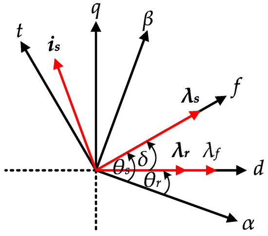
Figure 1.
Phasor diagram of the Interior permanent magnet synchronous motor (IPMSM).
The active flux λr is dependent on the d-axis component of the current, as shown in Equation (4). The flux linkage expressions can be written in terms of the f and t components as follows:
3. 3L-DTC for IPMSM
3.1. Torque and Stator Flux Estimation
As shown in Figure 2, the torque Te and stator flux λs is estimated based on the conventional voltage model, which requires only the information on the voltage and current vectors in the stationary (α–β) reference frame. The main feature of this control structure is that it maintains the simplicity of the classical DTC which is well known for controlling the electromagnetic torque and stator flux directly. In this scenario, the reference values of both the torque and flux are needed. The advantage of this control structure is that no need for the speed information for getting the torque reference value. The stator flux reference λs* is set to 0.56 Wb which is slightly higher than the permanent magnet flux λf. The estimation of these two variables is given by the following equations:
where P denotes the number of pole pair of the IPMSM.
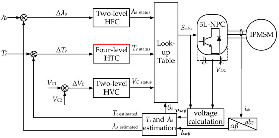
Figure 2.
Schematic block diagram of 3L- direct torque control (DTC) for IPMSM.
3.2. Three-Level NPC Inverter
The circuit topology and switching state vectors of a standard three-level NPC inverter are shown in Figure 3 and Figure 4, respectively. Eighteen voltage vectors are used to drive the IPMSM over a wide speed region. It is worth noting that the zero-voltage vector is not used in the IPMSM drives because it degrades the control of the stator flux linkage. Twenty-four different switching states represent the connections of the motor’s stator terminals to the DC-link terminals. The main advantage of employing this inverter is that the output voltage is synthesized with more discrete levels, when compared to a two-level inverter; therefore, the torque and flux ripples can be reduced.
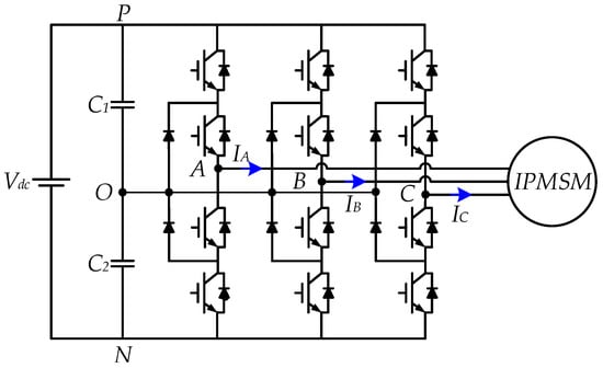
Figure 3.
Standard circuit topology of the three-level neutral-point clamped (NPC) inverter.
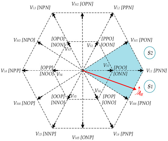
Figure 4.
Space vector diagram of the three-level NPC inverter.
The neutral-point voltage VNP of the three-level NPC inverter varies with the operating condition. If the VNP deviates too far, an uneven voltage distribution takes place, which may lead to premature failure of the switching devices and cause an increase in total harmonics distortion (THD) of the inverter output voltage. In Figure 4, the small voltage vectors (vS) of the three-level NPC inverter has positive (+) and negative (−) switching states. The (+) switching states means the phases are connected to (+) DC-link and neutral point. Meanwhile, a (–) switching state means that phases are connected to the neutral point and the (–) DC-link. The main cause of the VNP deviation is mostly because of the (+) and (–) switching states of the vS. vS+ is responsible for increasing the lower DC-link capacitor voltage, whereas the vS– decreases the lower DC-link capacitor voltage. One of the effective methods in balancing the VNP in 3L-DTC is using the hysteresis voltage controller (HVC) as shown in Figure 5.
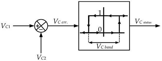
Figure 5.
Hysteresis for the three-level NPC inverter balancing control.
The operational principle is simplified in a few steps as shown in Figure 6. Firstly, both upper and lower capacitor voltages VC1 and VC2 are obtained. Then, if the upper DC-link capacitor voltage VC1 is higher than the lower DC-link capacitor voltage VC2 then (+) switching states are applied and if VC1 < VC2 then (–) switching states are applied. For simplicity, the output of the VNP balancing controller is VC status. The (+) switching states means the VC status is 1, meanwhile for (–) switching states, the VC status is 0. The HVC band size is set to 1% of the applied DC-link voltage which is about 3 V. This limitation will keep the VNP balanced in all operating conditions especially at low-speed region of the IPMSM.
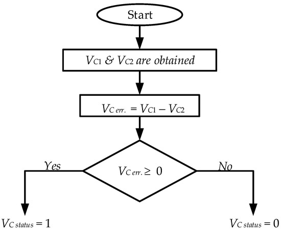
Figure 6.
Three-level NPC inverter balancing control.
3.3. Look-Up Table
The switching table used in the proposed 3L-DTC for the IPMSM drive is shown as Table 1. It is evident that the voltage vector space is divided into 12 sectors (S1–S12) of 30° each, as shown in Figure 4. These sectors are used to determine the position of the stator flux λs as it rotates in a space vector diagram of the three-level NPC inverter. For example, when the λs is in S1, and the IPMSM needs to operate in the low-speed region in the forward direction, vS2 needs to be selected to increase the Te. Similarly, to reduce the Te to match the lower band, vS5 needs to be selected. The arrangement of the look-up table is based on the output status of the four-level HTC, the two-level HFC, and the two-level HVC (see Figure 5 and Figure 7).

Table 1.
Look-up Table for 3L-DTC.
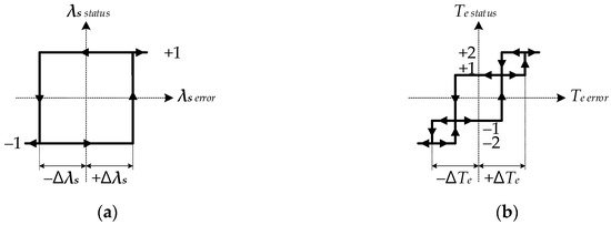
Figure 7.
Hysteresis controllers: (a) two-level hysteresis flux controller (HFC); (b) four-level hysteresis torque controller (HTC).
The output status of these controllers depends on the torque, flux, and NP demands. The rules for obtaining the output status of these controllers are given by the following equations:
The four-level HTC has four possible output states for all operating conditions of the torque response of the IPMSM. For example, when the torque status Te status is +2 and +1 the IPMSM is operating in medium—and high-speed regions are in the forward direction. While when the torque status Te status is −2 and −1 the IPMSM is operating in medium—and high-speed regions are in the reverse direction. The low-speed region requires only vS, which means the torque status Te status +1 and −1 need to be selected.
The same principle is applied to the two-level HFC and two-level HVC controllers. For example, for robust control of the flux in a circular trajectory, the flux status λs status output is 1 and −1 for increasing and decreasing the flux magnitude within the flux band. In the case of the HVC controller, when the vS+ is required, the VC status needs to be selected as 1 and when the vS− is required, the VC status needs to be selected as 0 to ensure the balancing of the VNP.
3.4. Conventional Four-Level HTC
The conventional four-level HTC design is shown in Figure 7b. By using this topology and the look-up table (see Table 1), the IPMSM can operate over a wide speed region with reduced torque ripples, when compared to that of the 2L-DTC. However, in the medium and high-speed regions, the torque is not controlled within the upper bands, which causes the stator current to drop due to the resulted offset in torque response. As shown in Figure 8, the torque is well controlled in the lower-torque bands when the IPMSM operates in the low-speed region.
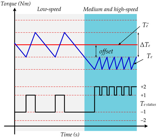
Figure 8.
Problem associated with the conventional four-level HTC.
The “+1” torque state increases the torque, while the “−1” torque state decreases the calculated torque. The operating speed of the IPMSM increases by more than half of the base speed, and the torque error exceeds that of the lower torque bands, which necessitates the application of the medium and large voltage vectors to achieve effective control in the medium and high-speed regions. As a result, the calculated torque does not follow the torque reference, which causes a drop in the stator current and degrades the performance of the 3L-DTC. Consequently, the calculated torque error average Te err. ave. in the medium and high-speed regions will be greater than that of the torque lower bands, when compared to that in the low-speed region operation.
3.5. Proposed Four-Level HTC
To solve the issues associated with the conventional four-level HTC, a simple algorithm based on Te err. ave is realized (see Figure 9). It only requires information of the calculated torque Te cal. and reference torque Te ref. to calculate the torque error Te err.; it then calculates its average Te err. ave.
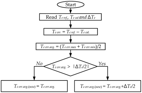
Figure 9.
Proposed torque capability improvement algorithm.
During low-speed operation, the calculated Te err. ave is zero because the torque reference lies in the middle of the lower torque bands. Therefore, the algorithm maintains the same operation in the low-speed region and only adds an offset of approximately half of the torque band to the precalculated Te err. ave in the medium- and high-speed regions. By using this proposed simple algorithm, the torque can be controlled over a wide speed region, and as a result, the stator current will be compensated.
4. Simulation Results
The system was simulated using the PSIM software tool to prove the robustness of the proposed four-level HTC over the conventional four-level-HTC-based DTC control methods for IPMSM drives. The IPMSM specifications and parameters for the simulation are presented in Table 2. The torque band ΔTe and flux band Δλs sizes were set to 3 Nm and 0.001 Wb, respectively. The sampling time for the proposed system was 70 μs to ensure that there was no calculation burden on the system under all operating conditions.
Table 2.
IPMSM Parameters.
Figure 10 shows the simulation results of the conventional and proposed four-level HTC strategies. It is evident that the issue of the offset in the torque response is present only in the medium and high-speed regions. The conventional four-level HTC has poor performance with respect to the torque response during the steady-state and dynamic response operations. The stator current peak value is peak in the low-speed region is 3.94 and 7.96 A at 5 and 15 Nm, respectively. However, is peak drops to 1.90 and 5.59 A at 5 and 15 Nm, respectively, because of the offset during the torque response to the reference torque value when the IPMSM operates at 600 r/min. This offset is compensated using the proposed algorithm, which results in a better torque response and stator current waveforms. The proposed four-level HTC improves the torque response in the medium- and high-speed regions and results in is peak compensation of 2.81 and 6.84 A at 5 and 15 Nm, respectively.
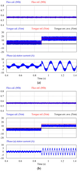
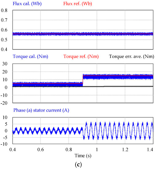
Figure 10.
Simulation results of the transient-state operation: (a) conventional four-level HTC at 150 r/min; (b) conventional four-level HTC at 600 r/min; (c) proposed four-level HTC at 600 r/min.
Figure 11 shows the simulation zoomed results of the conventional and proposed four-level HTC strategies. In Figure 11a, the torque response is well controlled where the operated speed of IPMSM is 150 r/min. The problem associated with the conventional four-level HTC in the torque response in clearly shown in Figure 11b. As a result of applying the proposed algorithm for improving the operation of the conventional four-level HTC in the medium and high-speed regions of the IPMSM, the torque response is improved, and the offset is compensated as shown in Figure 11c.
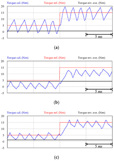
Figure 11.
Simulation zoomed results of the transient-state operation: (a) conventional four-level HTC at 150 r/min; (b) conventional four-level HTC at 600 r/min; (c) proposed four-level HTC at 600 r/min.
Figure 12 shows the simulation result of the four-level HTC at 150 r/min under NP balancing control of the three-level inverter. It is shown that the NP balancing control is robust even when a sudden torque load of 5 Nm is applied to the system. The NP balancing control keeps the DC-link VC1 and VC2 are balanced within the VC band.
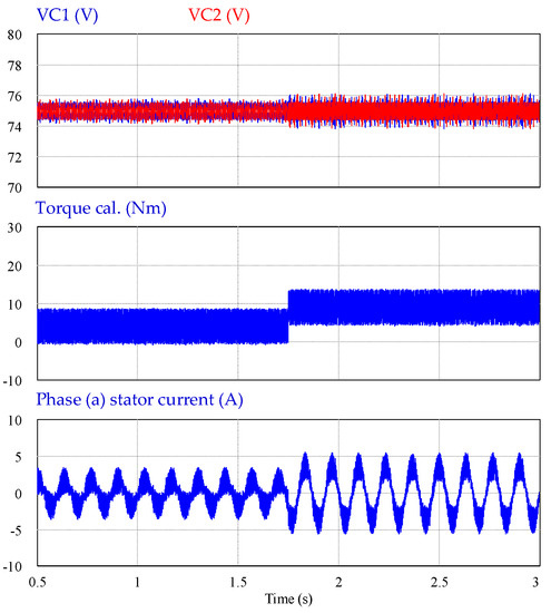
Figure 12.
Simulation result of the transient-state operation of the conventional four-level HTC under neutral-point balancing at 150 r/min.
5. Experimental Validation
Figure 13 shows the experimental setup used to verify the effectiveness of the proposed four-level-HTC–based DTC of the IPMSM drive. The hardware setup consists of a TMS320F28335 digital signal processor (DSP) control board, DC power supply, and an induction motor (IM), which is operated as a mechanical load and IPMSM. The control period of the system is set to 70 μs to ensure the robustness of the DTC under all operating conditions.
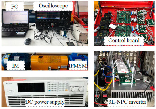
Figure 13.
Experimental setup.
Figure 14 shows the experimental results of the conventional and the proposed four-level-HTC-based DTC methods during transient-state operation when a sudden disturbance of an external load torque of 5 Nm is applied to the IPMSM during its operation at a constant speed of 400 r/min. Initially, the reference torque was set to 10 Nm; it was then stepped down to 5 Nm and stepped up to 10 Nm again. From the figure, the issue with the offset in the torque response associated with the conventional four-level HTC is evident. The torque error average is greater than the offset value; therefore, the simple proposed algorithm detects this offset in the torque response and then adds an offset to the Te err. ave to compensate for both the torque and stator current of the IPMSM. The zoomed results of both the conventional and proposed methods show the improvement achieved in both the torque and stator current responses during the steady-state and transient-state operations. The main advantage of the proposed method is that it does not require any speed information and operates normally without any issues in the low-speed regions as well.
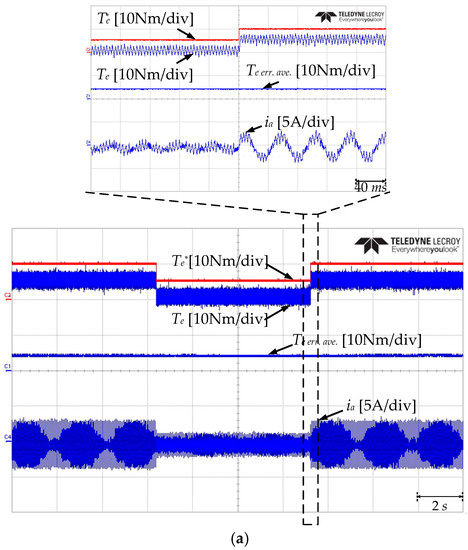
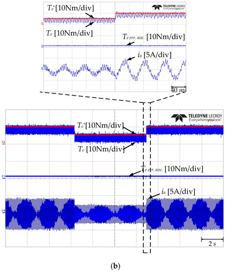
Figure 14.
Experimental results of the transient-state operation at 400 r/min: (a) conventional four-level HTC; (b) proposed four-level HTC.
Figure 15 shows the experimental result of the four-level HTC at 150 r/min under NP balancing control of the three-level inverter in the steady-state operation. It is shown that the NP balancing control is robust, and both the torque and stator current responses are well controlled. When a sudden torque load of 5 Nm is applied to the system as shown in Figure 16, the torque and stator current are under control due to the effective NP balancing control.
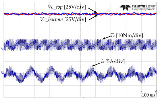
Figure 15.
Experimental result of the steady-state operation under neutral-point balancing at 150 r/min.
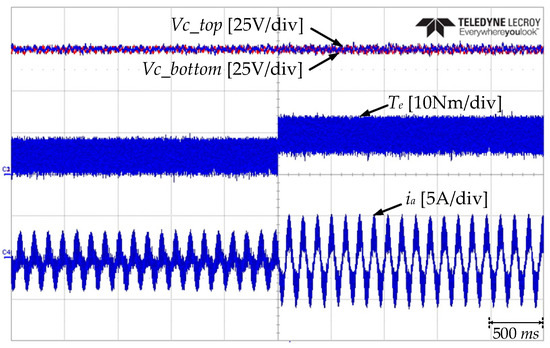
Figure 16.
Experimental result of the transient-state operation under neutral-point balancing at 150 r/min.
The zoomed experimental result of the torque response of the four-level HTC at 150 r/min is shown in Figure 17. It is clearly evident that the main merit of the DTC is attained as the torque follows the reference value when it changes from 5 Nm to 10 Nm.
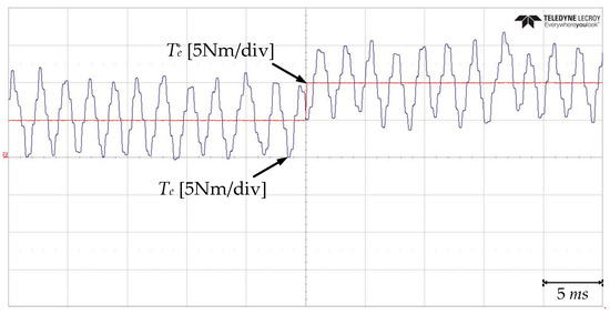
Figure 17.
Experimental zoomed result of the transient-state operation neutral-point balancing at 150 r/min.
6. Conclusions
In high-performance motor drives, a highly efficient system is required. The IPMSM machine is considered one of the highly efficient machines in the industry for its high-power density, high reliability, and wide constant-power operating range. Advanced control techniques are required for achieving a superior control of the IPMSM drives. Among these techniques is the well-known DTC which is presented in this paper. To reduce the torque and flux ripples, a four-level HTC has replaced the conventional two-level HTC for IPMSM drives fed by a three-level NPC inverter. Although, a great ripples reduction of both torque and stator flux has been achieved by using the four-level HTC, there is a poor torque response when the IPMSM operates in medium and high-speed regions. To alleviate this issue, a simple algorithm to improve the torque capability of an IPMSM in medium and high-speed regions is proposed. The proposed method modifies the conventional four-level HTC based on the torque error average calculation without requiring speed information. By using the proposed algorithm, the torque was controlled well in all speed regions, and hence, a better stator current waveform was achieved. The proposed method attains the advantage of classical DTC in the simplicity of implementation and a very quick dynamic response. In addition, there is no calculation burden in implementing the proposed method under various operating conditions. The simulation and experimental results indicate that the proposed four-level HTC for the 3L-DTC drives improves the torque response in the medium and high-speed regions and compensates the stator current. Moreover, the NP of the three-level NPC inverter is balanced in the steady-state and transient-state operations. Therefore, the proposed algorithm can be considered as a good choice for high-performance applications utilizing IPMSM drives.
Author Contributions
Conceptualization, methodology and formal analysis, S.S.H.; experimental validation, S.S.H.; writing—original draft preparation, S.S.H.; writing—review and editing the final manuscript, S.S.H. and K.-B.L.; resources and supervision, K.-B.L. All authors have read and agreed to the published version of the manuscript.
Funding
This research was supported by Korea Electric Power Corporation (Grant No. R19XO01-20) and a grant (20RTRP-B146008-03) from the Railroad Technology Research Program funded by the Ministry of Land, Infrastructure and Transport of the Korean government.
Acknowledgments
The authors would like to thank Power Electronics Laboratory colleagues of Electrical and Computer Engineering Department, Ajou University, South Korea.
Conflicts of Interest
The authors declare no conflict of interest.
References
- Vafaie, M.H.; Dehkordi, B.M.; Moallem, P.; Kiyoumarsi, A. A new predictive direct torque control method for improving both steady-state and transient-state operations of the PMSM. IEEE Trans. Power Electron. 2016, 31, 3738–3753. [Google Scholar] [CrossRef]
- Choi, Y.-S.; Choi, H.H.; Jung, J.-W. Feedback linearization direct torque control with reduced torque and flux ripples for IPMSM drives. IEEE Trans. Power Electron. 2016, 31, 3728–3737. [Google Scholar] [CrossRef]
- Wang, G.; Yang, L.; Yuan, B.; Wang, B.; Zhang, G.; Xu, D. Pseudo-random high-frequency square-wave voltage injection based sensorless control of IPMSM drives for audible noise reduction. IEEE Trans. Ind. Electron. 2016, 63, 7423–7433. [Google Scholar] [CrossRef]
- Ahn, H.; Park, H.; Kim, C.; Lee, H. A Review of State-of-the-art Techniques for PMSM Parameter Identification. J. Electr. Eng. Technol. 2020, 15, 1177–1187. [Google Scholar] [CrossRef]
- Zhong, L.; Rahman, M.F.; Hu, W.Y.; Lim, K.W. Analysis of direct torque control in permanent magnet synchronous motor drives. IEEE Trans. Power Electron. 1997, 12, 528–536. [Google Scholar] [CrossRef]
- Alsofyani, I.M.; Idris, N.R.N.; Lee, K.-B. Impact of Observability and Multi-objective Optimization on the Performance of Extended Kalman Filter for DTC of AC Machines. J. Electr. Eng. Technol. 2019, 14, 231–242. [Google Scholar] [CrossRef]
- Lee, K.-B.; Song, J.-H.; Choy, I.; Yoo, J.-Y. Improvement of low-speed operation performance of DTC for three-level inverter-fed induction motors. IEEE Trans. Ind. Electron. 2001, 48, 1006–1014. [Google Scholar]
- Siahbalaee, J.; Vaez-Zadeh, S.; Tahami, F. A Loss Minimization Control Strategy for Direct Torque Controlled Interior Permanent Magnet Synchronous Motors. J. Power Electron. 2009, 9, 940–948. [Google Scholar]
- Lee, K.-B.; Blaabjerg, F. Sensorless DTC-SVM for Induction Motor Driven by a Matrix Converter Using a Parameter Estimation Strategy. IEEE Trans. Ind. Electron. 2008, 55, 512–521. [Google Scholar] [CrossRef]
- Rashag, H.F.; Koh, S.P.; Abdalla, A.N.; Tan, N.M.L.; Chong, K.H. Modified Direct Torque Control using Algorithm Control of Stator Flux Estimation and Space Vector Modulation Based on Fuzzy Logic Control for Achieving High Performance from Induction Motors. J. Power Electron. 2013, 13, 369–380. [Google Scholar] [CrossRef]
- Abosh, A.H.; Zhu, Z.Q.; Ren, Y. Reduction of Torque and Flux Ripples in Space Vector Modulation-Based Direct Torque Control of Asymmetric Permanent Magnet Synchronous Machine. IEEE Trans. Power Electron. 2017, 32, 2976–2986. [Google Scholar] [CrossRef]
- Pacas, M.; Weber, J. Predictive direct torque control for the PM synchronous machine. IEEE Trans. Ind. Electron. 2005, 52, 1350–1356. [Google Scholar] [CrossRef]
- Cho, Y.; Lee, K.-B.; Song, J.-H.; Lee, Y.I. Torque-Ripple Minimization and Fast Dynamic Scheme for Torque Predictive Control of Permanent-Magnet Synchronous Motors. IEEE Trans. Power Electron. 2015, 30, 2182–2190. [Google Scholar] [CrossRef]
- Zhang, Y.; Xu, D.; Liu, J.; Gao, S.; Xu, W. Performance Improvement of Model-Predictive Current Control of Permanent Magnet Synchronous Motor Drives. IEEE Trans. Ind. Appl. 2017, 53, 3683–3695. [Google Scholar] [CrossRef]
- Zhou, Y.; Li, H.; Zhang, H.; Mao, J.; Huang, J. Model Free Deadbeat Predictive Speed Control of Surface-Mounted Permanent Magnet Synchronous Motor Drive system. J. Electr. Eng. Technol. 2019, 14, 265–274. [Google Scholar] [CrossRef]
- Bak, Y.; Jang, Y.; Lee, K.-B. Torque Predictive Control for Permanent Magnet Synchronous Motor Drives Using Indirect Matrix Converter. J. Power Electron. 2019, 19, 1536–1543. [Google Scholar]
- Zhang, T.; Chen, X.; Qi, C.; Lang, Z. Leg-By-Leg-Based Finite-Control-Set Model Predictive Control for Two-Level Voltage-Source Inverters. J. Power Electron. 2019, 19, 1162–1170. [Google Scholar]
- Xu, Y.; Li, H.; Ren, J.; Zhang, Y. Three-vector-based model predictive current control with disturbance feedforward compensation. J. Power Electron. 2020, 20, 687–697. [Google Scholar] [CrossRef]
- Feng, X.; Tao, Y.; Cui, X.; Shao, K.; Wang, Y. Sliding mode and predictive current control strategy of the three-phase Vienna rectifier. J. Power Electron. 2020, 20, 743–753. [Google Scholar] [CrossRef]
- Vafaie, M.H.; Dehkordi, B.M.; Moallem, P.; Kiyoumarsi, A. Minimizing Torque and Flux Ripples and Improving Dynamic Response of PMSM Using a Voltage Vector with Optimal Parameters. IEEE Trans. Ind. Electron. 2016, 63, 3876–3888. [Google Scholar] [CrossRef]
- Chen, W.; Zhao, Y.; Zhou, Z.; Yan, Y.; Xia, C. Torque Ripple Reduction in Three-Level Inverter-Fed Permanent Magnet Synchronous Motor Drives by Duty-Cycle Direct Torque Control Using an Evaluation Table. J. Power Electron. 2017, 17, 368–379. [Google Scholar] [CrossRef]
- Zhang, Y.; Zhu, J. A novel duty cycle control strategy to reduce both torque and flux ripples for DTC of permanent magnet synchronous motor drives with switching frequency reduction. IEEE Trans. Power Electron. 2011, 26, 3055–3067. [Google Scholar] [CrossRef]
- Zhu, H.; Xiao, X.; Li, Y. Torque ripple reduction of the torque predictive control scheme for permanent-magnet synchronous motors. IEEE Trans. Ind. Electron. 2012, 59, 871–877. [Google Scholar] [CrossRef]
- Niu, F.; Li, K.; Wang, Y. Direct Torque Control for Permanent-Magnet Synchronous Machines Based on Duty Ratio Modulation. IEEE Trans. Ind. Electron. 2015, 62, 6160–6170. [Google Scholar] [CrossRef]
- Lee, K.-B.; Lee, J.S. Reliability Improvement Technology for Power Converters; Springer: Singapore, 2017. [Google Scholar]
- Abronzini, U.; Attaianese, C.; D’Arpino, M.; Di Monaco, M.; Tomasso, G. Induction Motor Drives Fed by an NPC Inverter with Unbalanced DC-Link. Electronics 2019, 8, 1379. [Google Scholar] [CrossRef]
- Li, P.; Zhang, L.; Ouyang, B.; Liu, Y. Nonlinear Effects of Three-Level Neutral-Point Clamped Inverter on Speed Sensorless Control of Induction Motor. Electronics 2019, 8, 402. [Google Scholar] [CrossRef]
- Tuyen, N.D.; Phuong, L.M.; Lee, H. SVPWM Strategies for Three-level T-type Neutral-point-clamped Indirect Matrix Converter. J. Power Electron. 2019, 19, 944–955. [Google Scholar]
- Nair, M.D.; Biswas, J.; Vivek, G.; Barai, M. Optimum Hybrid SVPWM Technique for Three-level Inverter on the Basis of Minimum RMS Flux Ripple. J. Power Electron. 2019, 19, 413–430. [Google Scholar]
- Khojakhan, Y.; Choo, K.-M.; Won, C.-Y. Stator Inductance Identification Based on Low-Speed Tests for Three-Level NPC Inverter-Fed Induction Motor Drives. Electronics 2020, 9, 183. [Google Scholar] [CrossRef]
- Hakami, S.S.; Alsofyani, I.M.; Lee, K.-B. Improved Constant Switching Frequency Torque Regulator based DTC of IM Fed by 3L-NPC Inverter for Wide Speed Region. In Proceedings of the 2019 IEEE Conference on Energy Conversion (CENCON), Yogyakarta, Indonesia, 16–17 October 2019; pp. 42–46. [Google Scholar]
- Mohan, D.; Zhang, X.; Foo, G.H.B. Three-Level Inverter-Fed Direct Torque Control of IPMSM with Constant Switching Frequency and Torque Ripple Reduction. IEEE Trans. Ind. Electron. 2016, 63, 7908–7918. [Google Scholar] [CrossRef]
- Hakami, S.S.; Alsofyani, I.M.; Lee, K.-B. Low-Speed Performance Improvement of Direct Torque Control for Induction Motor Drives Fed by Three-Level NPC Inverter. Electronics 2020, 9, 77. [Google Scholar] [CrossRef]
- Naganathan, P.; Srinivas, S.; Ittamveettil, H. Five-level torque controller-based DTC method for a cascaded three-level inverter fed induction motor drive. IET Power Electron. 2017, 10, 1223–1230. [Google Scholar] [CrossRef]
- Hakami, S.S.; Alsofyani, I.M.; Lee, K.-B. Torque Ripple Reduction and Flux-droop Minimization of DTC with Improved Interleaving CSFTC of IM Fed by Three-Level NPC Inverter. IEEE Access. 2019, 7, 184266–184275. [Google Scholar] [CrossRef]
- Arumugam, S.; Thathan, M. Novel Switching Table for Direct Torque Controlled Permanent Magnet Synchronous Motors to Reduce Torque Ripple. J. Power Electron. 2013, 13, 939–954. [Google Scholar] [CrossRef]
- Pham, K.D.; Nguyen, N.V. Pulse-Width Modulation Strategy for Common Mode Voltage Elimination with Reduced Common Mode Voltage Spikes in Multilevel Inverters with Extension to Over-Modulation Mode. J. Power Electron. 2019, 19, 727–743. [Google Scholar]
- Jung, J.-H.; Park, J.-H.; Kim, J.-M.; Son, Y.-D. DC-Link Voltage Balance Control Using Fourth-Phase for 3-Phase 3-Level NPC PWM Converters with Common-Mode Voltage Reduction Technique. J. Power Electron. 2019, 19, 108–118. [Google Scholar]
- Wang, C.; Li, Z.; Xin, H. Neutral-point Voltage Balancing Strategy for Three-level Converter based on Disassembly of Zero Level. J. Power Electron. 2019, 19, 79–88. [Google Scholar]
- Yoon, H.; Yoon, D.; Choi, D.; Cho, Y. Three-phase current balancing strategy with distributed static series compensators. J. Power Electron. 2019, 19, 803–814. [Google Scholar]
- Li, C.; Wang, G.; Li, F.; Li, H.; Xia, Z.; Liu, Z. Fault-Tolerant Control for 5L-HNPC Inverter-Fed Induction Motor Drives with Finite Control Set Model Predictive Control Based on Hierarchical Optimization. J. Power Electron. 2019, 19, 989–999. [Google Scholar]
- Han, P.; He, X.; Zhao, Z.; Yu, H.; Wang, Y.; Peng, X.; Shu, Z. DC-Link Capacitor Voltage Balanced Modulation Strategy Based on Three-Level Neutral-Point-Clamped Cascaded Rectifiers. J. Power Electron. 2019, 19, 99–107. [Google Scholar]
- Guan, B.; Doki, S. Optimal Two Degrees-of-Freedom Based Neutral Point Potential Control for Three-Level Neutral Point Clamped Converters. J. Power Electron. 2019, 19, 119–133. [Google Scholar]


© 2020 by the authors. Licensee MDPI, Basel, Switzerland. This article is an open access article distributed under the terms and conditions of the Creative Commons Attribution (CC BY) license (http://creativecommons.org/licenses/by/4.0/).