Article

Development and Experimental Analysis of a Fuzzy Grey Control System on Rapeseed Cleaning Loss

1
College of Agricultural Engineering, Jiangsu University, Zhenjiang 212013, China
2
College of Automobile and Traffic Engineering, Nanjing Forestry University, Nanjing 210037, China
3
Jiangsu World Agricultural Machinery Co. Ltd., Zhenjiang 212013, China
*
Authors to whom correspondence should be addressed.
Electronics 2020, 9(11), 1764; https://doi.org/10.3390/electronics9111764
Submission received: 3 September 2020 / Revised: 14 October 2020 / Accepted: 16 October 2020 / Published: 23 October 2020

Abstract

:
One of the most important means of improving the mechanization of rapeseed harvests and increasing farmers’ income is to reduce the cleaning loss of rapeseed. In this study, a fuzzy grey control system was developed using an assembled cleaning loss sensor. Based on experimental data, the relationship between the cleaning loss and the opening of the louver sieve in the cleaning device was obtained. The fuzzy control scheme was established by combining grey prediction and the fuzzy control principle. Secondly, a microcontroller unit (MCU) was used as the controller, and the opening of the louver sieve was automatically regulated by detecting the signal of the cleaning loss. Finally, the performance and robustness of the control system was evaluated in field tests. Different experiments were conducted under different speed conditions to reflect the variable throughput. Results showed that using the grey prediction control system can realize the adjustment of the louver sieve opening in real time. The cleaning loss could be maintained within the ideal setpoint interval, compared with the operation with the control system switched off. These findings indicate that the application of the grey fuzzy control system reduces cleaning loss, and the nonlinear, time-variable and time delay problems in cleaning devices can be solved effectively.

Graphical Abstract

1. Introduction

The combine harvester has one of the most complex structures amongst agricultural machinery, in which the cleaning device is a core part. Cleaning performance is not only affected by working speed, feed rate, and working parameters, but also relates to the moisture, crop intensity, and geographical conditions. Cleaning loss is one of the main bottlenecks restricting the development of mechanized rapeseed harvesting [1,2], and is also an important indicator to evaluate the operating performance of rape combine harvesters. While working in the field, it is hard for the operator to guarantee the operation stability of the combine harvester when facing different varieties of crops and working conditions.
The cleaning loss and material other than grain (MOG) are significant cleaning performance parameters. There are two main reasons to select cleaning loss: on one hand, the vibration trend of MOG can be reflected in the cleaning loss to some extent. Thus, MOG can be controlled by controlling the cleaning loss. On the other hand, a large quantity of experimental data shows that the grain loss of modern harvesters is mainly due to cleaning. The reduction of cleaning loss is one of the most important methods for farmers to increase yield and income.
When the cleaning loss exceeds the expected range, manual adjustment is carried out according to the operator’s experience. This operation causes the cleaning loss to fluctuate, and the harvest performance to vary with each operator. Using this method, the working parameters of the cleaning device cannot be automatically adjusted in time, and harvesting timeliness and adaptability are poor, thereby restricting the potential economic benefits. Therefore, it is necessary to investigate adaptive control systems of the rapeseed cleaning loss.
To reduce the cleaning loss, it was vital to develop a mature monitoring device to monitor the cleaning loss in real time. At present, most scholars have analyzed the physical properties of different components in threshed outputs [3,4,5,6,7]. Based on different grain-sensitive monitoring boards, these authors hope to propose effective grain signals to distinguish material other than grain (MOG) in the grain bin and obtain the amount of cleaning loss. However, researchers mainly focus on the monitoring of rice, wheat, and soybean loss when harvested. Nevertheless, rapeseed is an important crop for the production of edible oil. Currently, literature on the monitoring of rapeseed sieve loss is rare [8]. Therefore, the monitoring accuracy of rapeseed seed loss needs to be further improved.
The research technologies of monitoring and controlling cleaning loss in well-known agricultural companies in Western countries are more advanced [9,10]. Combine harvesters produced by these companies are equipped with a comprehensive cleaning loss control system; for example, the JD9660STS type combine harvester produced by the John Deere Company in the United States, and the Ferguson860 type combine harvester produced by the Ferguson Company in the UK [11]. However, the grain monitoring and control system in Western countries mainly target wheat, soybean, and other grains, and few studies exist on sensors of small spherical grains such as rapeseed. Furthermore, the imported combine harvesters and regulating models from Western countries cannot fully adapt to the varieties of rapeseed in China (of which more than 700 exist [12]) that have different planting patterns (direct seeding, transplanting), grass-to-grain ratio, yield, and numerous other conditions. The actual operation performance is not ideal, and core monitoring sensors, such as loss, breakage, and impurity sensors, are not easy to implement in China due to the blockade on techniques from foreign countries.
Combine harvesters in Western countries are mainly wheeled harvesters designed for large farms, with a cutting width of 8–15 m and a weight of 20–30 tons. The main cropping pattern in China is the family farm, which consists of moderate-scale agriculture in the style of a small-scale peasant economy in large countries. Thus, this model of combine harvester cannot easily be applied to ensure working efficiency, particularly in the deep mud of rapeseed crops, in which it is easy to skid and sink. In addition, operational areas are restricted; the price of a single harvester is more than CNY 1.8 million, and these harvesters cannot adapt to the economic level of China’s agricultural industry. Due to these reasons, an automatic control system that is more suitable for rapeseed loss needs to be studied further.
Automatic control systems of cleaning loss, and other related devices, have been the focus of research in recent years. The main control methods are neural network control, Proportional Integral Derivative (PID) control, and fuzzy control [13]. The feed amount and loss rate of the combine in field work was researched by Miosz [14], and a working speed control model of the combine harvester was established. A fuzzy expert system in an intelligent decision support system was examined, and an expert system that modeled walking speed, threshing cylinder speed, and fan speed was proposed and employed by Dimitrov et al. [15]. Chaab et al. [16] conducted modeling and evaluation of header loss on a wheat combine harvester. The loss prediction model of the header used the dimensionless feature model based on Buckingham’s theorem. Fuzzy control has also been applied in the robot research field, such as soft motions in a car-like robot and robot manipulators with bounded inputs by Mercorelli et al. [17,18].
From the above, it can be seen that fuzzy control and prediction methods have been applied to the establishment and control of the loss and operating performance model of combine harvesters. This shows that modern control methods can describe and control combine harvester systems. However, performance prediction has only been mentioned in relation to rice, and few reports exist on the prediction and control of rapeseed loss.
To address the problems mentioned above, based on the assembled cleaning loss sensor, a fuzzy grey control method was adopted and an adaptive control system for rapeseed cleaning loss was established. In particular, the aim was to solve the problem of large and fluctuating cleaning losses in the harvest of rapeseed. The control system was tested in different conditions to examine the cleaning performance.

2. Materials and Methods

2.1. Monitoring The Cleaning Process

2.1.1. Cleaning Loss Monitoring Device

Based on our previous experience in designing a rapeseed grain loss sensor [19,20,21], an integrated multi-block cleaning loss monitoring structure was proposed. Four monitoring units were arranged and the monitored data from the four units were combined to estimate the overall rapeseed grain loss, so the required monitoring accuracy could be guaranteed [8]. The structure of the assembled cleaning loss sensor is shown in Figure 1. The sensor had been calibrated on the bench. Within the range of 2000 detected grains, the detection precision can reach 95.12%, which can satisfy the requirements of monitoring field cleaning loss.
The assembled cleaning loss sensor was arranged in the lateral direction of the tailing sieve. The connecting device between the assembled cleaning loss sensor and the combine harvester adopted T-section steel, and it was fitted to the outer surface of the machine. The installation method lengthens the transverse dimension of the sensor and avoids threshed outputs accumulating between the inner surface of the machine and the sensor. The range of the sensor installation angle can be adjusted within the range of 0–90° through angle adjuster plate, which can adapt to different combine harvester types. The installation position on the combine harvester is shown in Figure 2.
The control device was bolted to the harvester, close to the monitoring board, which is convenient for the signal wire connection. After receiving the cleaning loss signal output from the monitoring board, the controller makes corresponding adjustments to the cleaning parameters, such as fan speed and louver sieve opening.

2.1.2. Automatic Adjustment Device Introduction

Through the analysis of bench and field test data, it was found that the main factors affecting the rapeseed cleaning loss were the speed of the cleaning fan and the louver sieve opening. The reasons why this study regulated the louver sieve opening are as follows: (1) the cleaning fan of the medium and small size harvester commonly used in China is driven by a fixed-size belt wheel, meaning it is difficult to adjust the fan speed, and the cost of reconstruction is expensive. (2) From the perspective of future production and practicality, the adjustment of the louver sieve opening is relatively easy to realize. (3) Through the analysis of the experimental data, under the premise of the ideal airflow speed, the louver sieve opening has the greatest influence on the cleaning loss.
In order to adjust the louver sieve opening according to the cleaning loss, an adaptive adjustment device for the louver sieve opening was developed, as shown in Figure 3. The device was composed of an adjusting plate, pull rod, louver sieve, triangular block, connector, ball bearing and electric cylinder. In order to reduce the thrust of the electric cylinder, the triangular block was added, and its rotating arm lengthened. The motion of the electric cylinder push rod is horizontal, and the motion of the adjusting plate is circular around the axis, therefore it was necessary to add ball bearings to change the direction of the pull rod force. Point A of the pull rod was connected with the adjusting plate through joint bearing, and Point B was connected with the ball bearing. The ball bearing was connected with the pull rod of the electric cylinder by a connector, which converted the horizontal motion of the electric cylinder into the circular motion of the adjusting plate and changed the inclination angle of the louver sieves, enabling adjustment of the louver sieve opening.

2.2. Grey Fuzzy Controller Architecture

Due to the influence of field working conditions and rapeseed density, the operation process of the cleaning device is a nonlinear time-varying system [22]. In addition, there is serious lag in the process of regulating the louver sieve opening. In the previous research literature [23,24,25,26], the combination of grey prediction and fuzzy control methods provides a formal methodology for representing, manipulating and implementing heuristic knowledge in combination with experimental model-based knowledge into one control system. Therefore, the grey prediction fuzzy control theory is applied as the theoretical basis to designing the adaptive controller of rapeseed cleaning loss. The main program flow chart is shown in Figure 4.
The working process of fuzzy grey adaptive control systems can be described as: the predicted cleaning loss value is used as the input of the fuzzy grey controller, and through the prediction calculation of the fuzzy control algorithm, the variable quantity by which the louver sieve opening should adjust will be obtained. According to the output control signal of the variation in the louver sieve opening, the controller drives the electric pull rod to adjust the louver sieve opening, so as to reduce the cleaning loss. The control system mainly includes an initialization program, a subprogram with module driver function, and a grey prediction fuzzy control algorithm subprogram.

2.3. Fuzzy Controller

2.3.1. Determination of Monitoring Variable and Control Variable

The design process of the fuzzy controller, methods of standardizing input and blurring input, the definition and selection of fuzzy language variables, buildup of knowledge base, arithmetics and the realization of reasoning machine, fuzzy judgement, and so on, are brought forward [27]. The quantization table and fuzzy rule query table with input (cleaning loss per second deviation and its variation) and output (louver sieve opening) are established. The corresponding quantization level and the corresponding fuzzy quantity can be obtained by checking the quantization table containing the predicted deviation of input cleaning loss and its variation. Then, the output quantization level of the opening of the louver sieve can be acquired according to the fuzzy rule query table. Finally, the execution plan of the louver sieve opening adjusting mechanism is obtained from the quantization table.

2.3.2. Setpoint Estimator

On the premise of meeting the national standard [28] on rapeseed cleaning loss (total loss less than 8%, material other than grain (MOG) in the grain bin less than 6%), the cleaning loss was set at less than 4% in this study. At the same time, according to the previous relevant literature [29,30], the correlation between MOG and cleaning loss is a contrasting relationship: when the MOG increases, the loss rate decreases; when the MOG decreases, the loss rate increases. There is currently no existing mature product to detect MOG in China, thus in this study, the cleaning loss was chosen as the only performance parameter. When the cleaning loss reaches less than 1%, it is considered that the MOG exceeds the optimal range, and then the louver sieve opening is decreased to reduce the MOG; when the cleaning loss reaches more than 2%, the louver sieve opening is adjusted to reduce the cleaning loss.
In order to determine how much the cleaning loss needs to be adjusted during the harvesting process, the amount of cleaning loss in the field is calculated:
M s = A × L × V × S × 1000 × 1000 667 × M ,
where Ms is the amount of cleaning loss per second/particle; A is the rapeseed yield/kg; L is the cutting width of the rape combine harvester, m; V is the forward speed of the rape combine harvester, m/s; S is the cleaning loss rate/%; and M is the thousand-grain weight of rapeseed/g. In this study, A = 185 kg, L = 1.8 m, V = 1.0 m/s, Ms = 3.02 g.
The equation between the amount of cleaning loss detected by the sensor per second and the actual total cleaning loss per second is
Q s = M s × k ,
where Qs is the amount of cleaning loss that the sensor detects every second/particle; and k is the proportional coefficient of sensor monitoring. In this study, k = 0.14. The field detection loss rate ranged from 0 to 4%, and the cleaning loss monitored by the sensor ranged from 0 to 924 particles per second. In the control process of this study, the ideal loss setpoint was set to 1–2%. (The corresponding number of grains is 231 to 462 particles/second, which was calculated with Equations (1) and (2)).

2.3.3. Fuzzification of Input and Output

According to the above calculation of the cleaning loss and ideal interval, the basic range for cleaning loss deviation e ( t + Δ T ) and the basic range of the cleaning loss deviation variation Δ e C L ( t + Δ T ) are shown in Table 1.
In order to describe the variables in detail, the basic range is divided into 13 levels. The fuzzy subset range of cleaning loss deviation value e ( t + Δ T ) and cleaning loss deviation variation value Δ e C L ( t + Δ T ) are obtained as {−6,−5,−4,−3,−2,−1,0,1,2,3,4,5,6}. The corresponding cleaning loss deviation variation range is shown in Table 2. The corresponding set of fuzzy language variables are {Negative Big, Negative Medium, Negative Small, Zero, Positive Small, Positive Medium, and Positive Big}. These are abbreviated to {NB, NM, NS, ZO, PS, PM, PB}, respectively. If the language variable corresponding to the deviation value is positive, this indicates that the cleaning loss is higher than the ideal loss setpoint. If it is negative, this means that the cleaning loss is lower than the ideal loss setpoint.
The variation of the louver sieve opening was set as an output in this controller. The adjustable opening range of louver sieve selected in this study was from 13 to 26 mm, so the adjustable range was 13 mm. As shown in Figure 5, according to the bench test data, the cleaning loss deviation and the cleaning loss deviation variation of rapeseed showed a linear decreasing trend with the increase in the louver sieve opening. According to the trend between cleaning loss and louver sieve opening in Figure 5, and to balance the relationship between cleaning loss and MOG, the initial position of the louver sieve was set at the middle opening, which was about 17.2 mm. The basic range was −4.2–+8.8 mm. The negative sign indicates that the louver sieve opening decreases, while the positive sign indicates that the opening degree increases. The louver sieve opening is quantified according to proportion, as shown in Table 3.
According to the obtained quantization level as shown in Table 3, the corresponding fuzzy language of louver sieve opening variables are {Negative Big, Negative Medium, Negative Small, Zero, Positive Small, Positive Medium, and Positive Big}. These are abbreviated to {NB, NM, NS, ZO, PS, PM, PB}, respectively.
The input and output of the controller both adopt the triangular distribution with a fast control response as the membership function curve. According to Figure 6, the membership function assignment table for the cleaning loss deviation amount e ( t + Δ T ) , cleaning loss deviation variation amount Δ e C L ( t + Δ T ) , and louver sieve opening (output) can be obtained.

2.3.4. Formulate Fuzzy Rules

With the analysis of a large number of bench test data, the fuzzy value of corresponding controlling variables is obtained (Figure 5). The fuzzy control rules consider the gradual change of the working parameters to avoid the collision of the working parameters on the controller execution parts (such as the electric pull rod). According to the divided fuzzy interval, the fuzzy control rules of the louver sieve opening control are formulated, as shown in Table 4. In the field control process, according to the amount of cleaning loss deviation and cleaning loss deviation variation calculated by the controller, the fuzzy control rule table displays the corresponding control interval of the louver sieve opening. According to the membership function, the quantization level of louver sieve opening that needs to be adjusted is calculated, and the accurate value of opening degree regulation by defuzzification is obtained; where U is the value of the opening degree, E is e ( t + Δ T ) , and EC is Δ e C L ( t + Δ T ) .

2.4. Grey Prediction Controller

In order to solve the problem of system delay in the process between louver sieve controlling and sensor monitoring, grey predictive fuzzy control was formed by applying grey prediction GM (grey model) (1,1) into fuzzy control [31,32,33]. The grey prediction fuzzy control algorithm was applied to the adaptive control system of cleaning loss. Thereafter, the nonlinear and time-delay problems in the loss control process of rapeseed cleaning were solved.
According to the modeling steps of the GM (1,1) model, the cleaning loss can be predicted. The monitoring value of cleaning loss within a period of time was selected as the original data, the law was discovered, the predicted value sequence was obtained, the operation of the sequence was inversed, and then the predicted result was obtained. The parameters to be determined included the original sequence x C L ( 0 ) ( i ) (i = 1, 2, … n), the length of the sequence, the prediction of steps p, the development coefficient α, and the grey input μ [34]. The predicted results of the deviation and deviation variation per second were expressed as variables e ( t + Δ T ) and Δ e C L ( t + Δ T ) , respectively.
The original sequence was obtained from the sampling of the rapeseed cleaning loss sensor, and the original sequence length n was greater than or equal to 4. The control system obtains the cleaning loss n C L ( 0 ) ( t ) at each sampling, and the original sequence can be listed as:
n C L ( 0 ) = n C L ( 0 ) ( 1 ) , n C L ( 0 ) ( 2 ) , n C L ( 0 ) ( 3 ) , n C L ( 0 ) ( 4 ) ,
If the sampling period of the system is 1 s, the estimated response time between the cleaning loss impact to the sensor and the louver sieve opening adjustment is about 2 s, and the number of predicted steps is selected as p = 3.
The cleaning loss per second was positive, therefore the original data of cleaning loss per second can be directly accumulated to obtain the cumulative generation sequence of cleaning loss, as follows:
n ( 1 ) ( 1 ) = n C L ( 0 ) ( 1 ) , k = 1 n ( 1 ) ( 2 ) = n C L ( 0 ) ( 1 ) + n C L ( 0 ) ( 2 ) , k = 2 n ( 1 ) ( 3 ) = n C L ( 0 ) ( 1 ) + n C L ( 0 ) ( 2 ) + n C L ( 0 ) ( 3 ) , k = 3 n ( 1 ) ( 4 ) = n C L ( 0 ) ( 1 ) + n C L ( 0 ) ( 2 ) + n C L ( 0 ) ( 3 ) + n C L ( 0 ) ( 4 ) , k = 4
Background value z(1)(k) is
z ( 1 ) ( 2 ) = 0.5 ( n ( 1 ) ( 1 ) + n ( 1 ) ( 2 ) ) z ( 1 ) ( 3 ) = 0.5 ( n ( 1 ) ( 2 ) + n ( 1 ) ( 3 ) ) z ( 1 ) ( 3 ) = 0.5 ( n ( 1 ) ( 3 ) + n ( 1 ) ( 4 ) )
The matrix B and data vector XN can be obtained.
B = z ( 1 ) ( 2 ) 1 z ( 1 ) ( 3 ) 1 z ( 1 ) ( 4 ) 1
X N = n C L ( 0 ) ( 2 ) n C L ( 0 ) ( 3 ) n C L ( 0 ) ( 4 ) T
The transposition of B is equal to
B T = z ( 1 ) ( 2 ) z ( 1 ) ( 3 ) z ( 1 ) ( 4 ) 1 1 1
Four calculation parameters are defined:
C = k = 2 4 z ( 1 ) ( k ) D = k = 2 4 n C L ( 0 ) ( k ) E = k = 2 4 z ( 1 ) ( k ) n C L ( 0 ) ( k ) F = k = 2 4 ( z ( 1 ) ( k ) ) 2
Obtain:
B T B = F C C 1
( B T B ) 1 B T X N = 1 F C 2 C D E F D C E
Therefore, the Development Coefficient is calculated as:
α = C D E F C 2
Grey input is:
u = F D C E F C 2
After the above parameters are obtained, the predicted value of rapeseed cleaning loss n ^ C L ( 0 ) ( 4 + p ) after time p Δ t can be obtained, that is
n ^ C L ( 0 ) ( 4 + p ) = ( n C L ( 0 ) ( 4 ) u α ) e α p ( 1 e α )
The predicted deviation of cleaning loss is
e ^ ( t + Δ T ) = n ^ C L ( 0 ) ( 4 + p ) r ( t + p Δ t ) ,
The predicted deviation variation of cleaning loss is
Δ e ^ C L ( t + Δ T ) = e ^ ( t + Δ T ) e ^ ( t + Δ T 1 ) ,
The relative error was used to evaluate the accuracy of the predicted value, as shown in Table 5. Considering that the rapeseed cleaning system was a time-varying system, the second-order accuracy (5%) was used to evaluate the accuracy of the predicted loss value.

2.5. Overview of Monitoring Devices

The proposed adaptive control system for the cleaning section was tested on a World 4LZ-4.3 combine harvester. The grey fuzzy controller was implemented on a Microcontroller Unit (MCU) (STM32F40721T6, Nanjing NSCN Semiconductor Co., Ltd., Nanjing, China) system with C++ language. The adaptive control system of cleaning loss is mainly composed of a signal acquisition module, wireless transmission module, louver sieve opening adaptive actuator and an MCU controller. The signals, which are the cleaning loss and louver sieve opening, are broadcasted over the wireless transmission module. The cleaning loss signal is collected by an assembled cleaning loss sensor [8]. The elongation variation of the electric pull rod is transmitted to the signal acquisition system through a displacement sensor (Sonseiko@KTM-150MM, Shenzhen SONSEIKO Technology Co., Ltd., Shenzhen, China).
The maximum thrust of the electric cylinder pull rod is 200 N, and its longitudinal size is shorter and the weight is lighter, which can not only satisfy the installation size requirements, but also ensure the lightweight requirements and does not easily fall off. The measuring range of the displacement sensor is 150 mm, and its resolution is 0.01, which can meet the measuring requirements of the electric pull rod. The wiring diagram is shown in Figure 7.

3. Field Test Verification

3.1. Evaluation Procedure

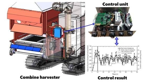
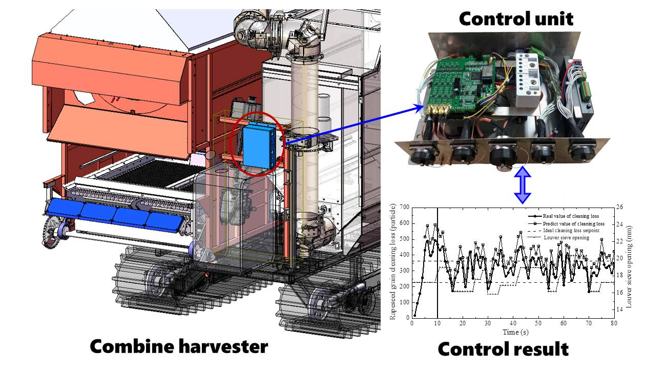
A grey fuzzy adaptive control system was developed for the combined harvester to adjust the louver sieve opening in real time, so as to keep the cleaning loss around the ideal loss setpoint. The field test of the rapeseed was conducted in the Oriental Oasis Modern Agriculture Park (Dafeng District, Yancheng, China) in June 2020. The rapeseed variety was “Zheyou 51”, and the rapeseed planting method was direct seeding. Aquacade dehydrating agent was sprayed before harvest. On the day of harvest, the color of the rape plant was dark yellow, the stalk pods were dried, and the rape was confirmed to be at full maturity. The natural properties are shown in Table 6.
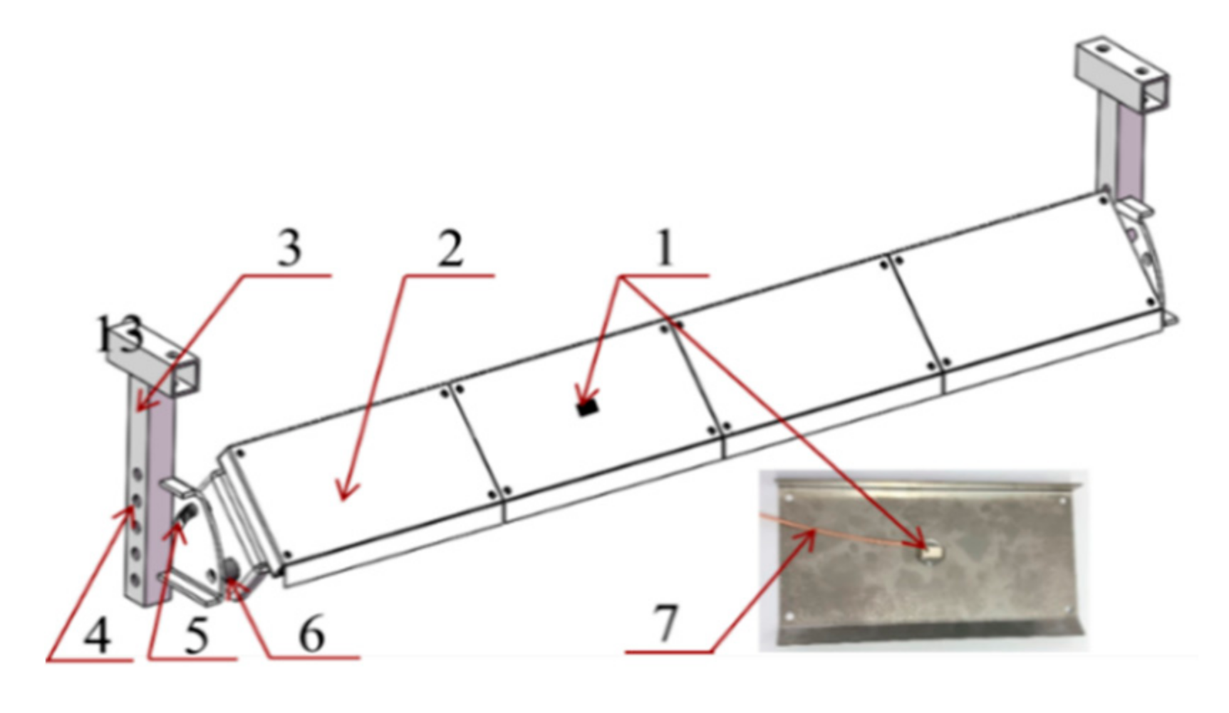
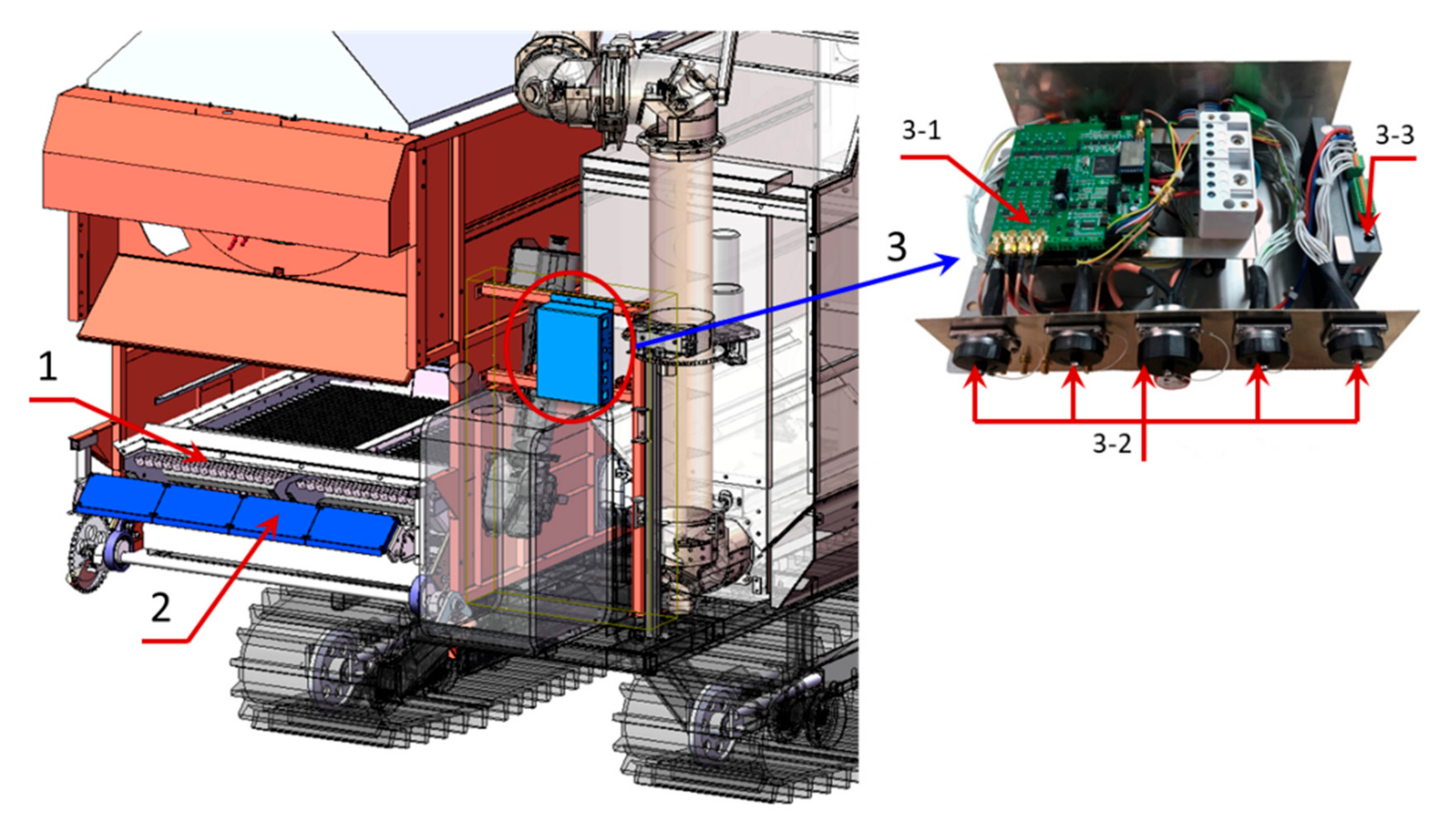
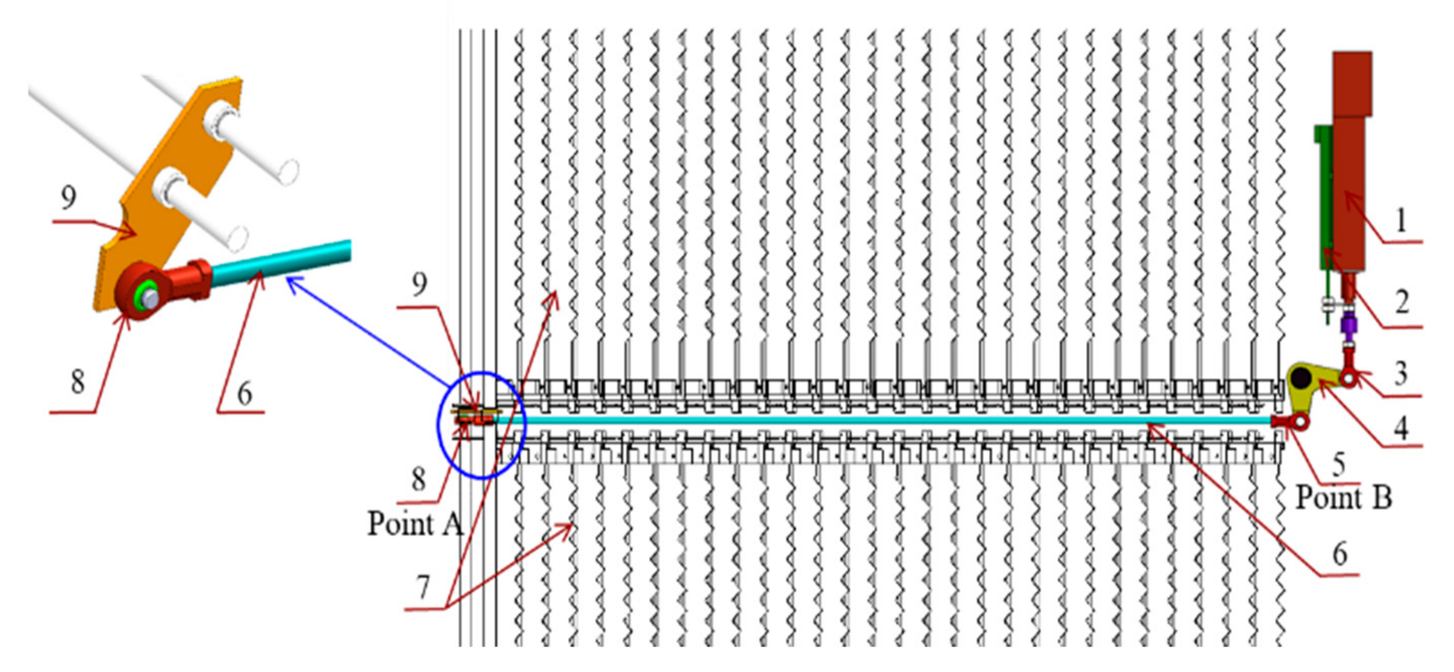
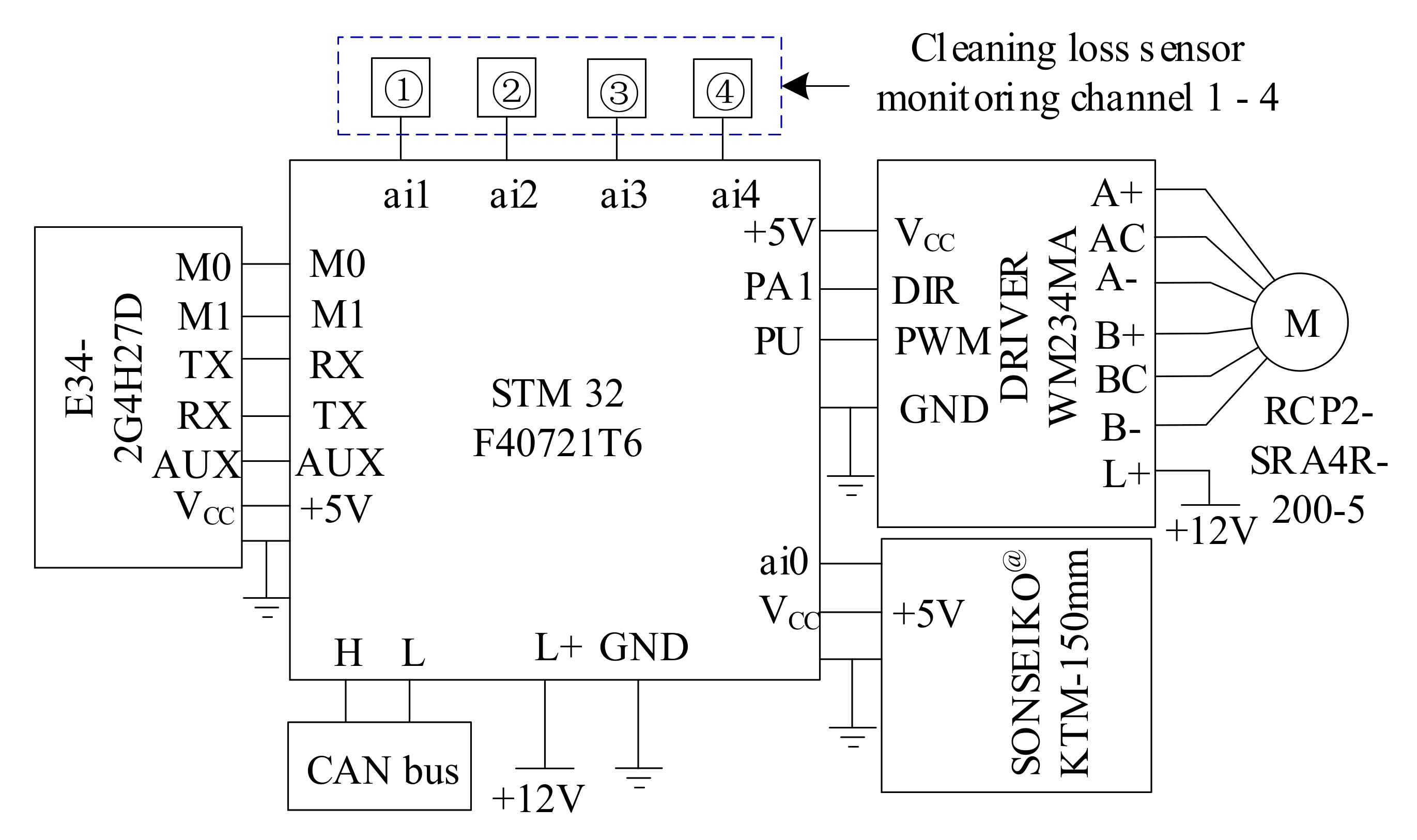
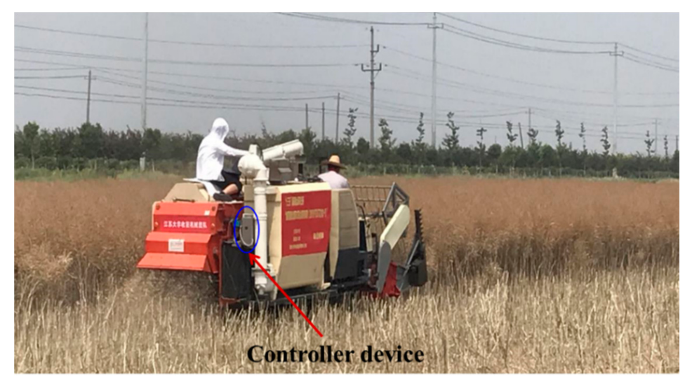
The cleaning loss sensor was installed at the rear of the tail sieve on a rapeseed combine harvester, 120 mm away from the vibrating sieve surface, and the adjusting angle was set as 45°. The controller device was installed near the assembled cleaning loss sensor to facilitate the connection of signal transmission lines. A section of the test field with a length of 80 m was measured, and a marker post was inserted at the beginning and the end. In the field test, the cutting width of the rapeseed combine harvester was 1.8 m, and the stubble height was 700 mm. The tangential threshing cylinder speed of the harvester was set at 570 r/min, the longitudinal axial flow threshing cylinder was set at 650 r/min, and the cleaning fan speed was set at 900 r/min. The field test is shown in Figure 8.
Two groups of experiments were carried, one with the control device switched off, and one with the switched-on grey fuzzy controller. The test group of the switched-off control device was used as the control group to test the practicability of the fuzzy grey algorithm. The experimental processes of the enabled control device are as follows: the rapeseed combine harvester started and worked for about 10 s, so that the rotation speed and feeding amount of each device on the machine could reach a stable state, and then the adaptive control system was started. During the continuous harvesting experiment the sensor monitoring value and the predicted value were recorded.

3.2. Results and Discussion

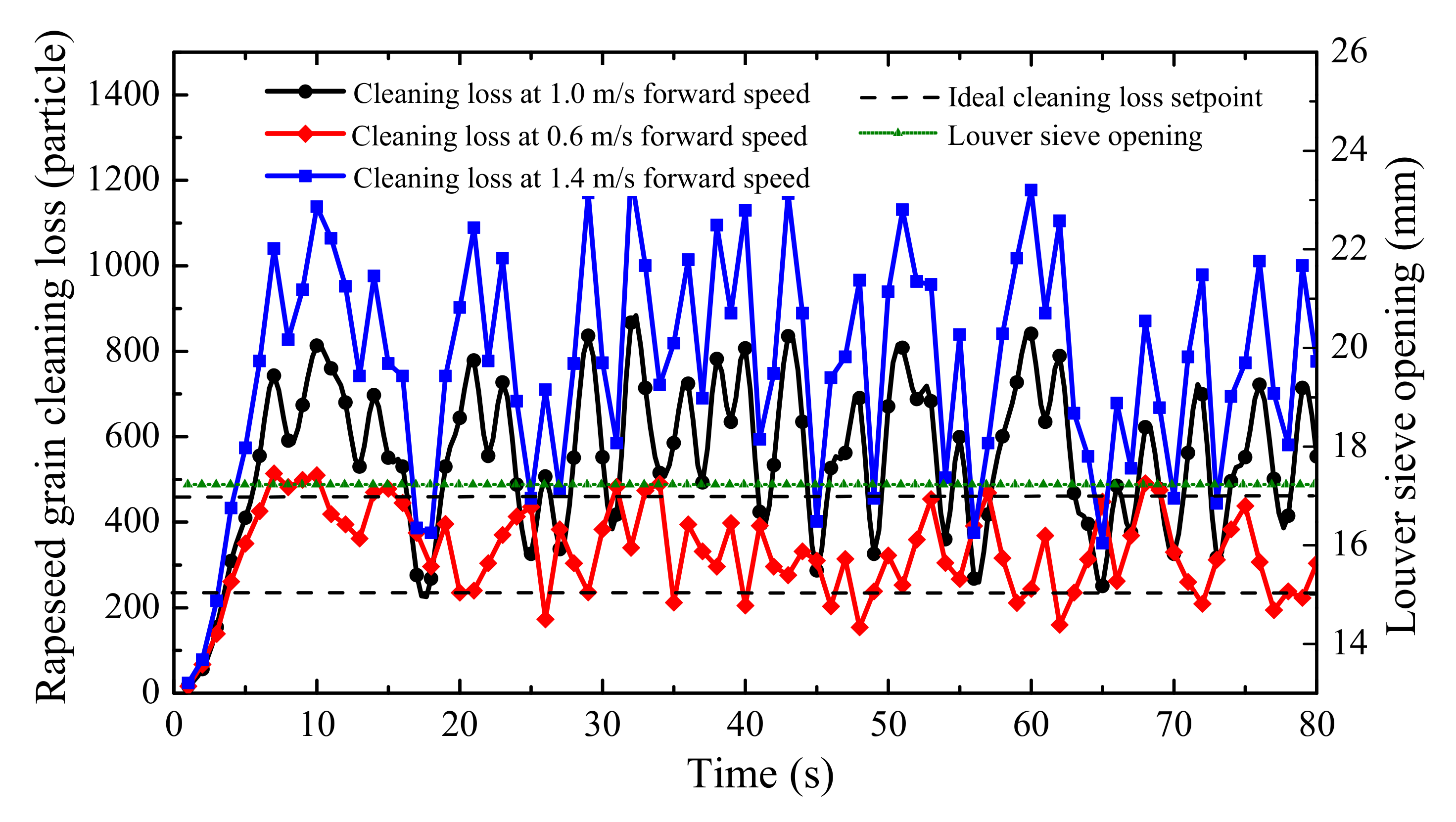
To verify the adaptation of fuzzy grey control systems, the cleaning loss was monitored under different field working conditions. The throughput is the main factor that affects cleaning loss during harvesting, so different forward speeds were taken to reflect the variation of throughput. Traditional harvesters have three speed levels, including low (0–0.8 m/s), middle (0.8–1.3 m/s) and high (1.3–1.8 m/s), therefore, a field test was conducted under each forward speed level with the controller switched off and switched on. The results of the tests with the controller switched off are shown in Figure 9.
It can be seen from Figure 9 that in the experimental group the controller is switched off (louver sieve opening = 17.2 mm). The cleaning loss rate under different forward speeds (0.6 m/s, 1.0 m/s, 1.4 m/s) with the controller switched off was 1.43%, 2.37% and 3.32%, respectively. This was lower than the 4% mentioned in Section 2.3.2, and was far lower than the 8% of the national standard [28].
Within 0–10 s, the main working components of combine harvesters gradually reach stability, and both the feeding quantity and the cleaning loss gradually increase. When the forward speed is 0.6 m/s, the cleaning loss ranges from 200 to 400 particles/second; when the forward speed is 1.0 m/s, the loss ranges from 400 to 800 particles/second; when the forward speed is 1.4 m/s, the loss ranges from 500 to 1000 particles/second. This indicated that the increase of throughput (mainly affected by the increase in forward speed) would cause the increase in cleaning loss.
To test the influence on cleaning loss caused by system time delay, the data for the forward speed 1 m/s in Figure 9 were analyzed (the normal harvest forward speed of combine harvesters is 1 m/s). The cleaning loss monitored by sensors at a moment was defined as the present value, the loss detected three seconds after the moment was defined as the time delay value. The corresponding regulating amount of louver sieve opening is shown in Figure 10, as the red line and black lines. The regulating amount represented the influence of cleaning loss. To more accurately reflect the effect of time delay on cleaning loss, the difference between the present value and time delay value were calculated, as shown in Figure 10 by the green line.
Time delay would cause the problem of lost or over-adjustment of the louver sieve opening. The negative value of the green line represents the lost adjustment of sieve opening, the positive value means the over-adjustment of sieve opening. The lost and over-adjustment reflects the influence on cleaning loss regulation caused by time delay problems. The maximum amount of lost adjustment is 6 mm, while the over-adjustment amount is 7 mm. Both of these have a great impact on the cleaning loss regulation.
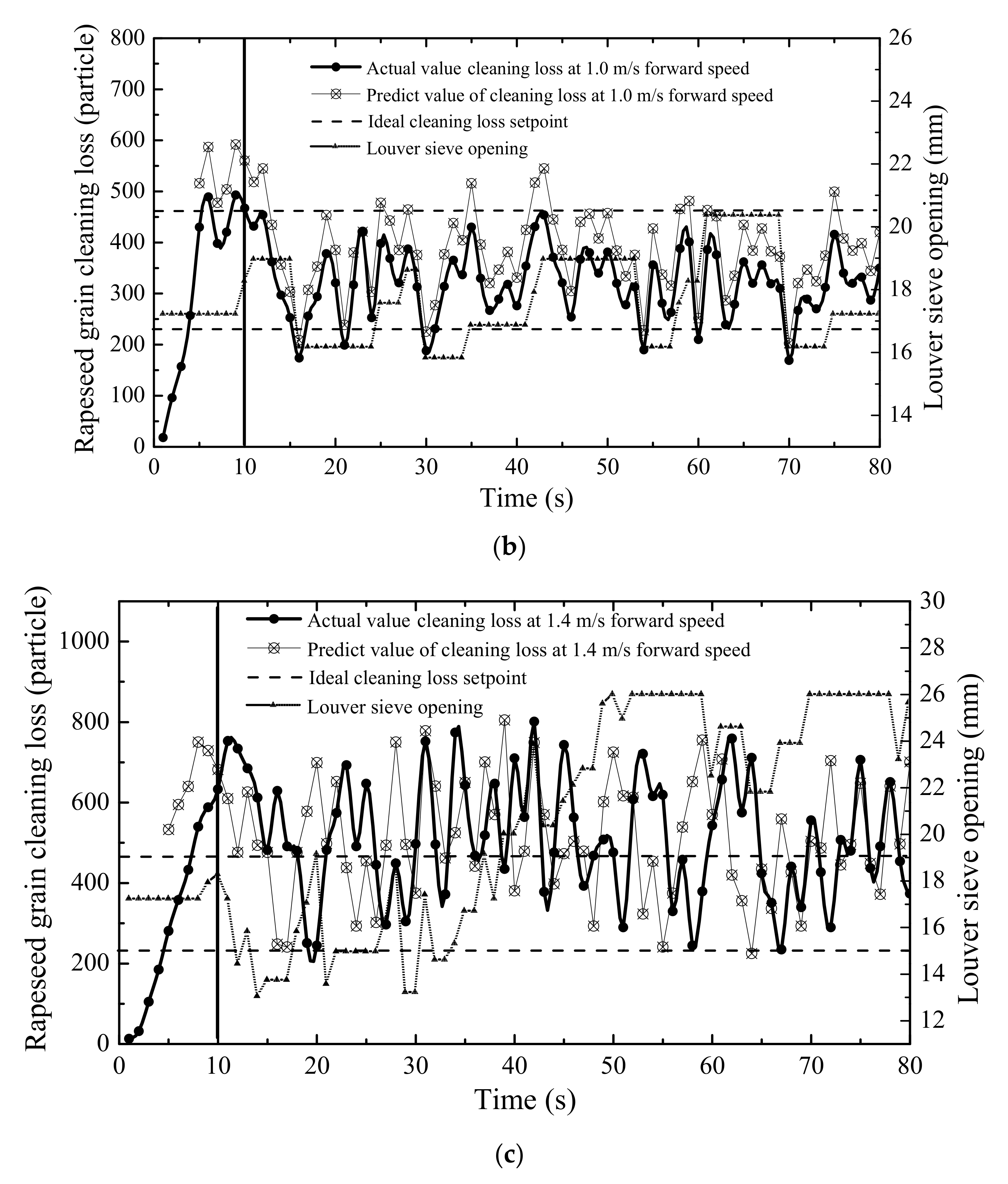
The switched-on cleaning system could effectively reduce the problem caused by time delay; the machine with the controller switched on was tested, as shown in Figure 11a–c, corresponding to the test results when the forward speed was 0.6 m/s, 1.0 m/s and 1.4 m/s, respectively.
The cleaning loss between 0 s and 80 s was counted. As can be seen from Figure 11a, when the forward speed was 0.6 m/s, cleaning loss stayed in the ideal interval after 25 s. The louver sieve opening was reduced to the minimum value, indicating that the reduction in throughput can decrease cleaning loss, and it was unnecessary to switch on the control device when the forward speed was low.
In the test group Figure 11b, when the grey fuzzy control device was switched on at 10 s, it can be seen that the cleaning loss gradually decreased and become stable at 15 s. In the range of 15–80 s, the cleaning loss was between 250 and 450 particles/second, and the average loss was 383 particles/second.
As can be seen from Figure 11c, the cleaning loss between 50 s and 80 s were counted. When forward speed was 1.4 m/s, the cleaning loss was far beyond the ideal interval. Thus, when the forward speed was high in the field, the louver sieve opening could be kept at the maximum to reduce cleaning loss.
The data collected with the controller switched on and off at three different forward speed levels were compared, and the results are shown in Table 7. These parameters were the average results from different repetitions, which were calculated according to the experiments conducted three times.
It can be seen from Table 7 that the total loss rate and the percentage of MOG both show a downward trend after the controller was switched on. The root mean square error (RMS) was decreased by 49.92% at most. The use of the fuzzy grey controller reduced the fluctuation of field cleaning loss. It can be concluded that the fuzzy grey control system for the cleaning shoe increases the cleaning performance of the combine harvester. This is consistent with the conclusion proposed by Craessaerts [35], who applied the fuzzy control algorithm to control the cleaning system.
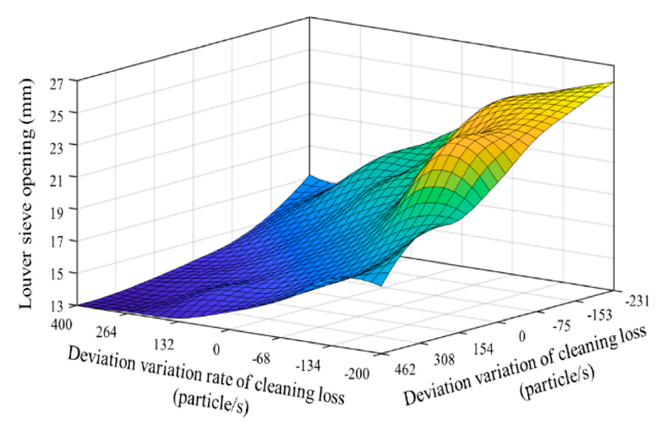
The above analysis shows that the cleaning loss value between the experimental group and test group has a significant difference. With the increase in monitored cleaning loss, the louver sieve opening increased to reduce it, and vice versa. Though the opening degree of louver sieve has an influence on the cleaning loss, a period of time is needed to realize the adjustment of deviation to keep cleaning loss among the setting range. Thus, there exists a fluctuation in the process of cleaning loss adjustment.
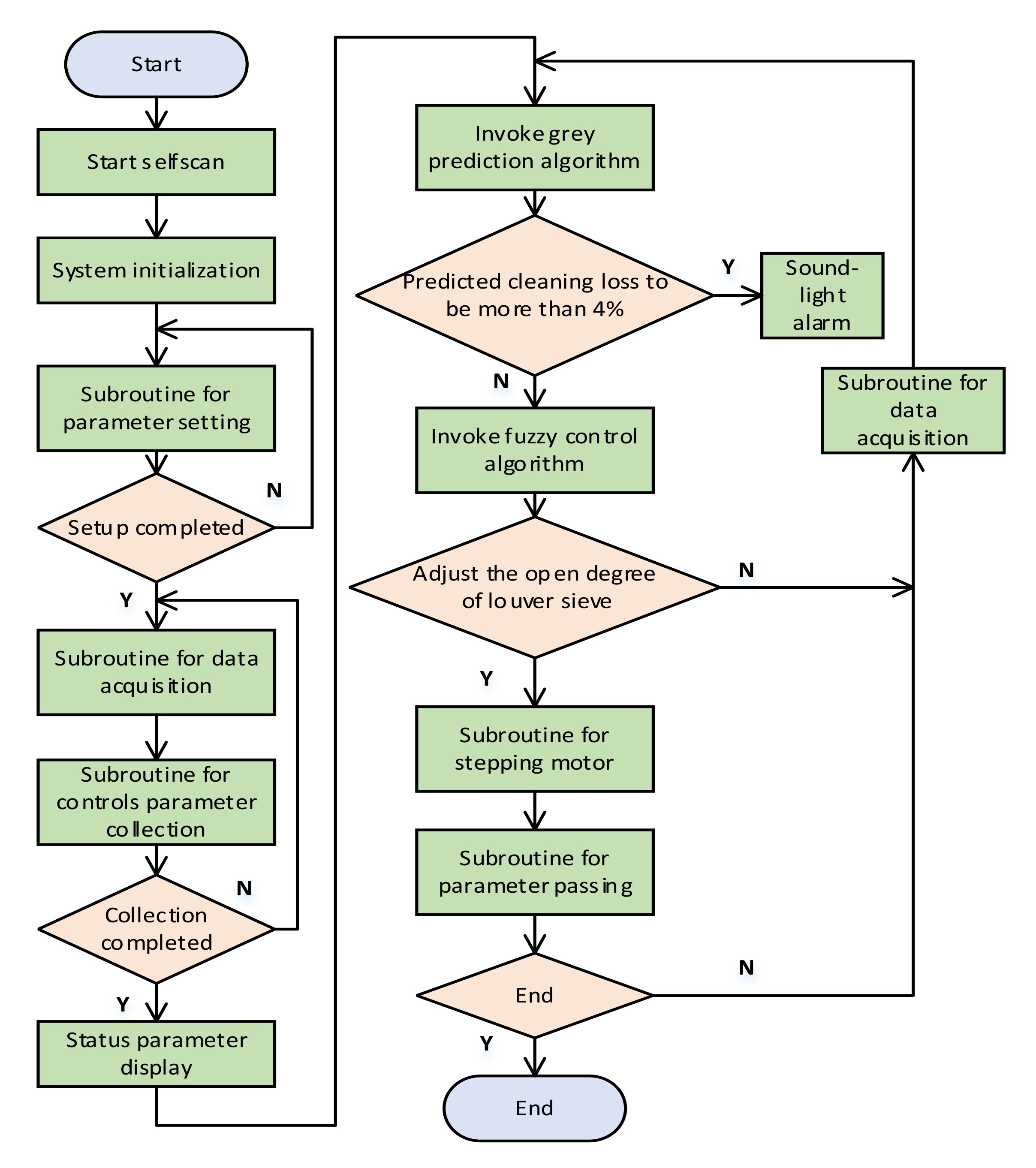
Predicted cleaning loss was consistent with the actual monitored cleaning loss, which was about 3 s in advance of the actual monitored loss, consistent with the theoretical design in Section 2.4. The relative errors between the actual monitored cleaning loss and predicted cleaning loss were within 5%. The second-order accuracy of the algorithm was realized and the predicted cleaning loss was satisfied. These analyses illustrate that the grey prediction algorithm can predict future change rules. Thus, the predicted future change rules can solve the time delay problems by offsetting the time between the prediction process and system calculation and execution.
The analysis above indicates that, in the regulating process, as for the change of crop density or the influence of field environment, the fuzzy grey control system can realize the adjustment to reach the ideal interval within a period of time, demonstrating the benefits of an automatic control system for the cleaning section of a combine harvester when environmental conditions rapidly change over time.

4. Conclusions

Aimed at the lack of automatic control of the rapeseed cleaning loss monitoring system and the non-linear, time-varying and time delay characteristics of the rape combine harvester cleaning device, a fuzzy grey control system for the cleaning unit has been elaborated. The main goal of the control system was to maintain an optimal trade-off between acceptable cleaning losses.
A grey prediction algorithm was used to solve the time delay problem caused by the time required from system calculation to the execution device. This grey prediction method can provide a way of thinking for weather forecasting, earthquake forecasting and pest forecasting. At the same time, the fuzzy grey control device and algorithm developed in this study can lay a foundation for solving the nonlinear, time-varying and time delay problems existing in other agricultural machinery systems in field operation.
The performance and robustness of the control system have been evaluated by field tests during rapeseed harvest. Different walking speeds were selected as the variable working conditions to reflect the change of the throughput. Promising results were obtained; the cleaning loss, MOG and RMS of cleaning loss all decreased after the control system was switched on, compared with results from when it was switched off. The control device can adjust and control itself according to the prediction. The research results can provide a reference for the reduction in harvest losses of combine harvesters, and the developing intelligence of agricultural equipment.

Author Contributions

Conceptualization, X.C.; Methodology, X.C.; Software, Y.L. (Yang Li); Validation, J.Q.; Formal Analysis, X.C.; Writing-Original Draft Preparation, L.L.; Writing-Review & Editing, L.X., Y.L. (Yaoming Li); Funding Acquisition, L.X., Y.Z. All authors have read and agreed to the published version of the manuscript.

Funding

This research was funded by the Earmarked Fund for China Agriculture Research System (CARS-12), leading talents of national "ten thousand talents program", Postgraduate Research & Practice Innovation Program of Jiangsu Province (KYCX19_1617), Jiangsu Agriculture Science and Technology Innovation Fund (JASTIF), (CX(19)3083), and "Six talent peaks" Innovation Talent Team of Jiangsu Province (TD-GDZB-005).

Conflicts of Interest

The authors declare no conflict of interest.

References

  1. Xu, L.Z.; Li, Y.M.; Ma, C.X.; He, Z.F.; Lv, F. Design of main working parts of 4LYB1-2.0 rape combine harvester. Trans. CSAM 2008, 8, 54–57. [Google Scholar]
  2. Liang, Z.; Li, Y.; Xu, L.; Zhao, Z. Sensor for monitoring rice grain sieve losses in combine harvesters. Biosyst. Eng. 2016, 147, 51–66. [Google Scholar] [CrossRef]
  3. Wang, X.Z.; Zhang, S.Z. Dynamic analysis of grain impact on grain loss sensor of combine harvester. J. Agric. Mech. Res. 1997, 2, 56–59. [Google Scholar]
  4. Mao, H.P.; Li, P.P. Design of intelligent grain cleaning losses monitor based on array piezocrystals. Trans. CSAM 2010, 41, 175–177. [Google Scholar]
  5. Gao, J.M.; Zhang, G.; Yu, L.; Li, Y.B. Chaos detection of grain impact at combine cleaning loss sensor. Trans. CSAE 2011, 27, 22–27. [Google Scholar]
  6. Zhao, Z.; Li, Y.; Chen, J.; Xu, J. Grain separation loss monitoring system in combine harvester. Comput. Electron. Agric. 2011, 76, 183–188. [Google Scholar] [CrossRef]
  7. Zhuo, W.; Che, D.; Bai, X.P.; Hu, H.C. Improvement and experiment of cleaning loss rate monitoring device for corn combine harvester. Trans. CSAM 2018, 49, 100–108. [Google Scholar]
  8. Xu, L.; Wei, C.; Liang, Z.; Chai, X.; Li, Y.; Liu, Q. Development of rapeseed cleaning loss monitoring system and experiments in a combine harvester. Biosyst. Eng. 2019, 178, 118–130. [Google Scholar] [CrossRef]
  9. Botterill John, R.; Kepkay Leslie, L.; Dodd Philip, L.; Radburn William, J. Combine grain loss signal, Massey Ferguson Services. U.S. Patent US3593720, 20 July 1971. [Google Scholar]
  10. Strelioff, W.P.; Elliott, W.S.; Johnson, D. Grain Loss Monitor. U.S. Patent US4036065 A, 19 July 1977. [Google Scholar]
  11. Wang, Z.H. Research on the Cleaning Performance of the Wind-Screen Cleaning Device of the Rape Combine Harvester; Jiangsu University: Zhenjiang, China, 2018. [Google Scholar]
  12. Rapeseed Varieties, Seed Business Network. Available online: https://www.chinaseed114.com/seed/youcai (accessed on 15 August 2020).
  13. Liang, Z.W. Study on Designing Method of Multi-Duct Air-and-Screen Cleaning Unit and Grain Sieve Loss Monitoring and Controlling Technology; Jiangsu University: Zhenjiang, China, 2018. [Google Scholar]
  14. Miosz, T. Quality of combine-harvester performance as affected by construction of selected threshing-separating assemblies. Problemy Inzynierii Rolniczej 1994, 2, 23–34. [Google Scholar]
  15. Dimitrov, V.; Borisova, L.; Nurutdinova, I. Modelling of fuzzy expert information in the problem of a machine technological adjustment. MATEC Web Conf. 2017, 132, 4009. [Google Scholar] [CrossRef]
  16. Chaab, R.K.; Karparvarfard, S.H.; Rahmanian-Koushkaki, H.; Mortezaei, A.; Mohammadi, M. Predicting header wheat loss in a combine harvester, a new approach. J. Saudi Soc. Agric. Sci. 2020, 19, 179–184. [Google Scholar] [CrossRef]
  17. Mercorelli, P. Using fuzzy PD controllers for soft motions in a car-like robot. Adv. Sci. Technol. Eng. Syst. J. 2018, 3, 380–390. [Google Scholar] [CrossRef] [Green Version]
  18. Zheng, C.; Su, Y.X.; Mercorelli, P. A Simple Fuzzy Controller for Robot Manipulators with Bounded Inputs. In Proceedings of the IEEE/ASME International Conference on Advanced Intelligent Mechatronics (AIM), Munich, Germany, 3–7 July 2017; pp. 1737–1742. [Google Scholar] [CrossRef]
  19. Liang, Z.W.; Li, Y.M.; Zhao, Z.; Xu, L.Z. Structure optimization of a grain impact piezoelectric sensor and its a lication for monitoring separation losses on tangentialaxial combine harvesters. Sensors 2015, 15, 1496–1517. [Google Scholar] [CrossRef] [PubMed] [Green Version]
  20. Liang, Z.W.; Li, Y.M.; Zhao, Z.; Chen, Y. Structure optimization and performance experiment of grain loss monitoring sensor in combine harvester in using modal analysis. Trans. CSAE 2013, 29, 22–29. [Google Scholar]
  21. Liang, Z.; Li, Y.; Zhao, Z.; Xu, L.; Li, Y. Optimum design of grain sieve losses monitoring sensor utilizing partial constrained viscoelastic layer damping (PCLD) treatment. Sens. Actuators A Phys. 2015, 233, 71–82. [Google Scholar] [CrossRef]
  22. Liang, Z.; Li, Y.; Xu, L. Grain sieve loss fuzzy control system in rice combine harvesters. Appl. Sci. 2018, 9, 114. [Google Scholar] [CrossRef] [Green Version]
  23. Craessaerts, G.; Saeys, W.; Missotten, B.; De Baerdemaeker, J. Identification of the cleaning process on combine harvesters. Part I: A fuzzy model for prediction of the material other than grain (MOG) content in the grain bin. Biosyst. Eng. 2008, 101, 42–49. [Google Scholar] [CrossRef]
  24. Craessaerts, G.; Saeys, W.; Missotten, B.; De Baerdemaeker, J. Identification of the cleaning process on combine harvesters, Part II: A fuzzy model for prediction of the sieve losses. Biosyst. Eng. 2010, 106, 97–102. [Google Scholar] [CrossRef]
  25. Ning, X.B.; Chen, J.; Li, Y.M.; Wang, K.; Wang, Y.F.; Wang, X.L. Kinetic model of combine harvester threshing system and simulation and experiment of speed control. Trans. CSAM 2015, 31, 25–34. [Google Scholar]
  26. Ning, X.B.; Chen, J.; Li, Y.M.; Yang, G.J.; Wu, P.; Chen, S. Multi-objective genetic algorithm optimization of forward speed of fuzzy control system for combine harvester. Trans. CSAM 2015, 46, 68–74. [Google Scholar]
  27. Ning, X.B.; Chen, J.; Li, Y.M.; Yang, G.J.; Wu, P. Fuzzy adaptive control system of forward speed for combine harvester based on model reference. Trans. CSAM 2014, 45, 86–91. [Google Scholar]
  28. Ministry of Agriculture of the People’s Republic of China, NY/T 2199–2012. Operation Quality of Rape Combine Harvesters; China Standard Press: Beijing, China, 2012.
  29. Craessaerts, G.; Saeys, W.; Missotten, B.; De Baerdemaeker, J. A genetic input selection methodology for identification of the cleaning process on a combine harvester, Part II: Selection of relevant input variables for identification of material other than grain (MOG) content in the grain bin. Biosyst. Eng. 2007, 98, 297–303. [Google Scholar] [CrossRef] [Green Version]
  30. Craessaerts, G.; Saeys, W.; Missotten, B.; De Baerdemaeker, J. A genetic input selection methodology for identification of the cleaning process on a combine harvester, Part I: Selection of relevant input variables for identification of the sieve losses. Biosyst. Eng. 2007, 98, 166–175. [Google Scholar] [CrossRef]
  31. Liu, X.; Zhang, B.; Yang, L.B.; Yu, X.F. Intelligent train operation system of urban rail transit based on grey predictive fuzzy adaptive PID control. Meas. Control. Tech. 2020, 39, 109–113. [Google Scholar]
  32. Cai, Z.X. Intelligent Control; Electronic Industry Press: Beijing, China, 2004. [Google Scholar]
  33. Chou, Y.; Liu, M.; Zhang, Z.D.; Huang, R.L. Research on a location of fuzzy neural network in combine harvester. In Proceedings of the Fifth International Conference on Fuzzy Systems and Knowledge Discovery, Shandong, China, 18–20 October 2008; p. 3. [Google Scholar]
  34. Qian, J.X.; Zhao, J.; Xu, Z.H. Predictive Control; Chemical Industry Press: Beijing, China, 2007. [Google Scholar]
  35. Craessaerts, G.; De Baerdemaeker, J.; Missotten, B.; Saeys, W. Fuzzy control of the cleaning process on a combine harvester. Biosyst. Eng. 2010, 106, 103–111. [Google Scholar] [CrossRef]
Figure 1. Diagram of assembled cleaning loss sensor structure. (1) Sensitive element, (2) Sensitive plate, (3) Support frame (T-section steel), (4) Installation longitudinal direction adjuster hole, (5) Installation angle adjuster plate, (6) Vibration isolation rubber, (7) Monitoring unit.
Electronics 09 01764 g001
Figure 2. Sensor and control device installation position. (1) Tail sieve, (2) Assembled cleaning loss sensor, (3) Adaptive control device of cleaning loss, (3-1) Controller, (3-2) Aviation plug, (3-3). Driver.
Electronics 09 01764 g002
Figure 3. Adaptive adjustment device for the louver sieve opening. (1) Electric cylinder, (2) Displacement sensor, (3) Ball bearing, (4) Triangular block, (5) Ball bearing (Point B), (6) Pull rod, (7) Louver sieve, (8) Joint bearing (Point A) connector, (9) Adjusting plate.
Electronics 09 01764 g003
Figure 4. Control system hardware block diagram.
Electronics 09 01764 g004
Figure 5. Effect of louver sieve opening on cleaning loss.
Electronics 09 01764 g005
Figure 6. Membership function of e ( t + Δ T ) and Δ e C L ( t + Δ T ) for cleaning loss and the louver sieve opening.
Electronics 09 01764 g006
Figure 7. Wiring diagram of the grey fuzzy controller.
Electronics 09 01764 g007
Figure 8. Field test.
Electronics 09 01764 g008
Figure 9. Field test with the controller switched off.
Electronics 09 01764 g09
Figure 10. The impact on cleaning loss caused by time delay.
Electronics 09 01764 g010
Figure 11. Grain cleaning loss under different working speeds with the controller switched on. (a) Forward speed 0.6 m/s; (b) Forward speed 1.0 m/s; (c) Forward speed 1.4 m/s.
Electronics 09 01764 g011aElectronics 09 01764 g011b
Table 1. Variation range of the cleaning performance.
ItemDeviation DomainVariation of the Deviation Domain
Cleaning loss amount[−231, +462], particles/second[−200, +400], particles/second
Table 2. Quantification table for cleaning sieve loss.
Quantization LevelVariation Range of Cleaning Loss Deviation, Particle/SecondVariation Range of Cleaning Loss Deviation, Particle/Second
−6< −231< −200
−5−231–−192−200–−167
−4−192–−153−167–−134
−3−153–−114−134–−101
−2−114–−75−101–−68
−1−75–−36−68–−35
0−36–+77−35–+66
1+77–+154+66–+132
2+154–+231+132–+198
3+231–+308+198–+264
4+308–+385+264–+330
5+385–+462+330–+400
6>+462>+400
Table 3. Quantification table for louver sieve opening.
Quantization LevelLouver Sieve Opening Degree/mm
−6−4.2
−5−3.5
−4−2.8
−3−2.1
−2−1.4
−1−0.7
00
11.4
22.8
34.2
45.6
57
68.8
Table 4. Fuzzy control strategy for louver sieve opening.
UENBNMNSZOPSPMPB
EC
NBPBPBPMPMPSZOZO
NMPBPBPMPSPSZONS
NSPMPMPSPSZONSNS
ZOPMPMPSZONSNMNM
PSPSPSZONSNSNMNM
PMPSZONSNMNMNMNB
PBZOZONMNMNMNBNB
Note: U is the fuzzy language variable of the louver sieve opening, E is the cleaning loss deviation, and EC is the cleaning loss deviation variation. NB is negative big, NM is negative middle, NS is negative small, ZO is zero, PS is positive small, PM is positive middle, and PB is positive big.
Table 5. Calculation of relative error
ResidualRelative Error
ε ( n ) = n ^ CL ( 0 ) ( n ) n ^ CL ( 0 ) ( n + p ) Δ n = ε ( n ) n ^ C L ( 0 ) ( n )
Table 6. Natural properties of rapeseed.
Natural Properties ParameterYield Per ha/kgAverage Plant Height/mmPod Height/mmPod Diameter/mm1000-grain Weight/gMoisture Content/%
Value10,00517007004503.8214.50
Table 7. Comparison of cleaning parameters between controllers switched on and off.
Forward Speed m/s
0.61.01.4
Percentage reduction in the cleaning loss rate of switched-on controller compared to switched-off controller, %32.1631.6436.14
Percentage reduction in the material other than grain (MOG) rate of switched-on controller compared to switched-off controller, %32.2525.0032.22
Percentage of the root mean square error (RMS) of cleaning loss between switched-on controller compared to switched-off controller, %31.3049.9236.00
Publisher’s Note: MDPI stays neutral with regard to jurisdictional claims in published maps and institutional affiliations.

