Article

An Approach for Optimal Coordination of Over-Current Relays in Microgrids with Distributed Generation

by
Sergio D. Saldarriaga-Zuluaga
1,2,
Jesús M. López-Lezama
2,* and
Nicolás Muñoz-Galeano
2
1
Departamento de Eléctrica, Facultad de Ingenieria, Institución Universitaria Pascual Bravo, Calle 73 No. 73A-226, Medellín 050036, Colombia
2
Grupo en Manejo Eficiente de la Energía (GIMEL), Departamento de Ingeniería Eléctrica, Universidad de Antioquia (UdeA), Calle 70 No. 52-21, Medellín 050010, Colombia
*
Author to whom correspondence should be addressed.
Electronics 2020, 9(10), 1740; https://doi.org/10.3390/electronics9101740
Submission received: 29 September 2020 / Revised: 15 October 2020 / Accepted: 15 October 2020 / Published: 21 October 2020

Abstract

:
The ever increasing presence of renewable distributed generation (DG) in microgrids is imposing new challenges in protection coordination. The high penetration of renewable DG enables microgrids to operate under different topologies, giving rise to bidirectional power flows and in consequence, rendering traditional coordination approaches inappropriate to guarantee network security. This paper proposes an approach for the optimal coordination of directional over-current relays (OCRs) in microgrids that integrate renewable DG and feature several operational modes. As a main contribution, the characteristic curves of directional OCRs are considered to be decision variables, instead of fixing a single type of curve for all relays as considered in previous works. The proposed approach allows for the selection of several IEC and IEEE curves which combination results in the best protection coordination. Several tests were carried out on an IEC benchmark microgrid in order to show the applicability of the proposed approach. Furthermore, a comparison with other coordination approaches evidenced that the proposed approach is able to find lower operation times and, at the same time, guarantee the suitable operation of protections under different condition faults and operational modes.

1. Introduction

Nowadays, the rapid incorporation of renewable DG in modern distribution networks (DNs) has introduced new paradigms to the traditional energy generation scheme. Basically, for high standards of quality, energy management, and efficiency; DG has been configured into microgrids that favor the rapid use of renewable energy resources. Such incorporation brings along new challenges for engineers and designers around the world [1,2].
The protection coordination problem ine of these challenges. DG changed the traditional configuration of unidirectional power flows in DNs where there is only a single generation bus. With the presence of DG, there are multiple generation buses that produce bidirectional power flows and variable short circuit levels [3]. In general terms, new protection systems must guarantee the stability of the protection scheme not only under intermittent DG units and loads, but also under the possibility of switching between grid-connected and islanded modes [4,5].
Directional over-current relays (OCRs) have been used in traditional DNs, and they are presented as a promissory alternative for the protection of microgrids [6,7]. Nonetheless, their suitable incorporation and optimal coordination in microgrids remains a research topic [8]. In this context, it is of paramount importance the incorporation of new approaches in the planing and designing of coordination schemes aiming to high standards of velocity, selectivity, and reliability [9].
Several approaches for improving the protection coordination in microgrids have been reported in the specialized literature. In [10], an approach for OCRs coordination for grid-connected and islanded operational modes is proposed. This approach takes into account changes in network topology due to line or generation outages. In [11], a protection coordination scheme for microgrids is proposed by utilising the commonly used numerical directional OCRs with single and dual settings. The authors in [12] simultaneously incorporate a multi-objective particle swarm optimization (PSO) technique and a decision tool for coordinating OCRs in microgrids. In [13], an adaptive protection coordination scheme is developed based on a machine-learning approach. The authors modelled a hybrid artificial neural network and a support vector machine approach for modifying protection settings while guaranteeing the reliability of the network. In [14], the authors implemented a protection coordination with smart electronic devices and a communication channel; this for obtaining real-time system information and updating relays settings.
Recently, there have been some studies regarding the optimal protection coordination problem in microgrids, which relay on a better setting of the characteristics for standard and non-standard curves. In [15], a new constraint regarding the plug setting multiplier (PSM) is proposed for improving the coordination of directional OCRs in microgrids. This constraint is also incorporated in [16], using a non-standard curve for enhancing the performance of OCRs protection. In [17], the authors considered the upper limit of the PSM as a variable, changing the traditional paradigm in which it is seen as a fixed limit. Additionally, the constraint proposed in [15] was included considering a normal inverse current curve for all relays. In [18], the coordination of directional OCRs in microgrids is carried out for grid-connected and islanded modes while considering different IEC characteristic curves for each relay.
This paper proposes a new model for OCRs coordination in microgrids that takes multiple operational modes and DG into account. As a novelty, the proposed model considers the characteristic curves of the relays as decision variables, which differentiates it from other works that consider a single type of curve for all relays [15,16,17,18]. As can be seen from the literature review, several models and solution techniques have been used to solve the optimal coordination of OCRs in microgrids. In this sense, our paper complements the research of [18] which only takes into account some IEC curves by introducing both IEC and IEEE standard curves [19,20]. The proposed approach also considers the constraint proposed in [15] regarding the PSM. These features enlarge the solution space of the coordination problem and allow for finding better solutions. Several tests were performed on a benchmark IEC microgrid when considering four operational modes. To prove the effectiveness of the proposed approach, the results were compared with those that were reported in [15,16,17]. In all operational modes, the proposed approach was able to find a better coordination scheme. Furthermore, the proposed approach can be used in order to obtain a coordination with multiple parameters for each operational mode or a single set of parameters that are suitable for all operational modes. Table 1 shows the features of other research works in the field, evidencing the knowledge gap in the existing literature that is filled by the proposed approach.
This paper is organized, as follows: Section 2 presents the problem formulation, Section 3 shows the genetic algorithm used to solve the coordination problem, Section 4 presents the results, and Section 5 concludes and summarizes the most relevant aspects of the research.

2. Mathematical Formulation

2.1. Objective Function

Equation (1) illustrates the objective function (OF) which consists on minimizing the operation time of the OCRs while ensuring coordination between main and back up relays. m and n are the number of relays and faults in the system, respectively; while, t i f corresponds to the operation time of relay i when fault f takes place.
O F = M i n i = 1 m f = 1 n t i f

2.2. Coordination Criteria

The coordination between main and back up relays is enforced by constraint (2). When a fault takes place, both of the relays identify the fault occurrence. However, it must be guaranteed that the main relay is tripped first. This is achieved by defining a coordination time interval C T I which is the time difference between the tripping of the main and back up relays. In this case, t j f is the operation time of the backup relay j when fault f occurs, and t i f is the operation time of the primary relay i, for the same fault. The yypical C T I values are within the range of 0.2 to 0.5 s. The C T I considered in this study is 0.3 for comparative purposes. Equation (3) indicates the operating time limits of the OCRs. In this case, t i m i n and t i m a x are the minimum and maximum operating time of relay i, respectively.
t j f t i f C T I
t i m i n t i f t i m a x

2.3. Relay Characteristic

Equation (4) accounts for the type of standard characteristic curve (IEC or IEEE), where A, B, and C are constant parameters of the curve, T M S i is the time multiplier setting of relay i, and P S M i f is the ratio between the fault current I f i and the pick up current i p i c k u p i given by Equation (5). This ratio must be between minimum ( P S M i m i n ) and maximum ( P S M i m a x ) limits, as indicated by constraint (6).
t i f = A . T M S i P S M i f B 1 + C
P S M i f = I f i i p i c k u p i
P S M i m i n P S M i f P S M i m a x

2.4. Bonds on the TMS and Pick up Current for Each Relay

In the conventional approach of protection coordination, the T M S is the main decision variable. Equation (7) represents the minimum and maximum limits of T M S for relay i given by T M S i m i n and T M S i m a x , respectively. Similarly, Equation (8) represents lower and upper limits of the pickup current i p i c k u p i , denoted as i p i c k u p i m i n and i p i c k u p i m a x , respectively.
T M S i m i n T M S i T M S i m a x
i p i c k u p i m i n i p i c k u p i i p i c k u p i m a x

2.5. New Constraint Considering Standard Curves

Equation (9) represents the selection of the IEC/IEEE standard characteristic curve. The curve setting of a relay provides information regarding the type of characteristic curve to be followed by that particular relay. In this case, S t a n d a r C u r v e i is the select standard characteristic curve of the primary relay i. In this Equation, Ω c represents the set of standard curves that are available in the relay.
S t a n d a r C u r v e i Ω c

3. Methodology

The optimal coordination of OCRs given by (1)–(9) is a non-convex optimization problem that involves discrete and continuous decision variables. Non-convex optimization problems may have multiple locally optimal solutions and it can take a lot of time to identify whether the problem has no solution at all or whether the solution found is globally optimal. There are multiple solution techniques that can be applied in order to solve the optimization problem that is given by (1)–(9). The most suitable among them belong to the set of metaheuristic techniques, since they are able to tackle non-convex optimization problems and find high-quality solutions in relatively low computational time. In this case, the proposed optimization problem was solved by a conventional genetic algorithm (GA) that wasimplemented in Matlab. It is worth mentioning that the main contribution of this paper considers the characteristic curves of OCRs as decision variables of the coordination problem, and not the solution technique as such. In this sense, hybrid versions of GA such as its combination with simulated annealing [21,22] have proven to outperformed its conventional version and might be the subject of future research. Genetic algorithms mimic the process of natural selection, starting with an initial population of solution candidates that must pass through several stages of selection, crossover, and mutation. Other metaheuristics, such as particle swarm optimization [23] and differential evolution [24], have also been applied for solving the optimal coordination of protections. Furthermore, GAs have been successfully applied in the coordination of OCRs, as presented in [18,25,26].

3.1. Initial Population

The starting point of a GA is a set of candidate solutions or population. Every candidate solution (or individual) is represented by a vector that contains the proposed values of the decision variables. In this case, each individual is represented with a vector that indicates the settings of T M S and S t a n d a r C u r v e i for each relay; therefore, the length of a candidate solution is twice the number of relays in the network. The initial population is randomly generated while taking the limits of the decision variables into account. Figure 1 depicts an example of a candidate solution.

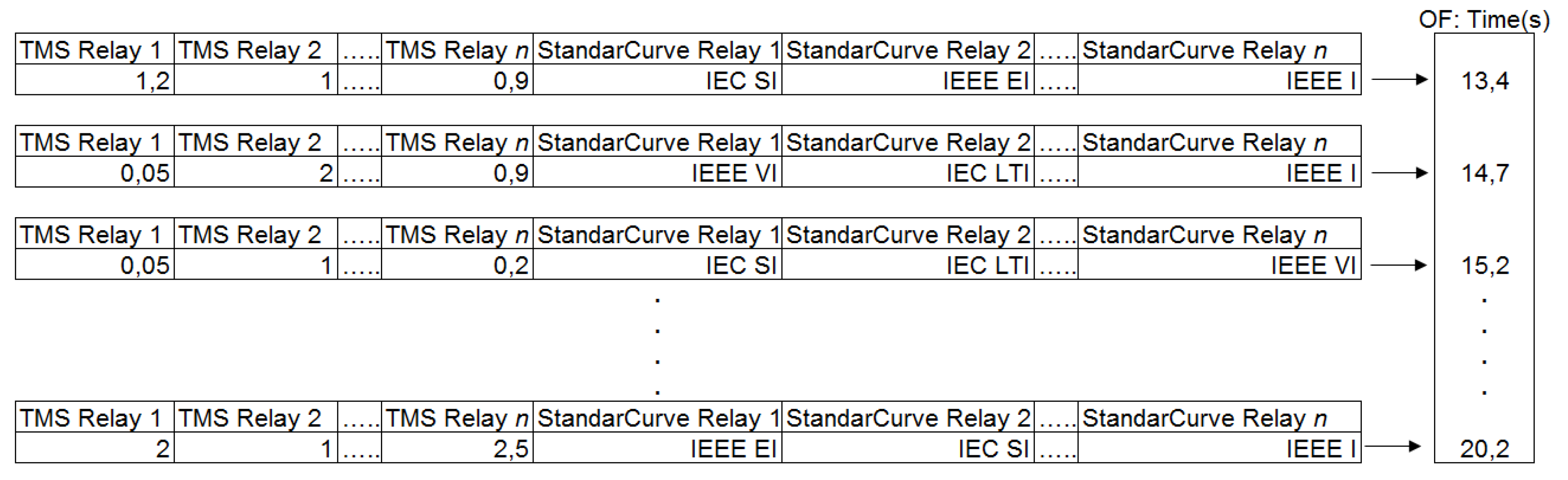
3.2. Fitness Evaluation

Once a set of solution candidates is generated, it is necessary to evaluate the quality of such possible solutions. This is known as the stage of fitness evaluation. In this case, the objective function (given by Equation (1)) that is associated with every solution candidate is evaluated and they are sorted from best to worst. Figure 2 depicts the process of fitness evaluation.

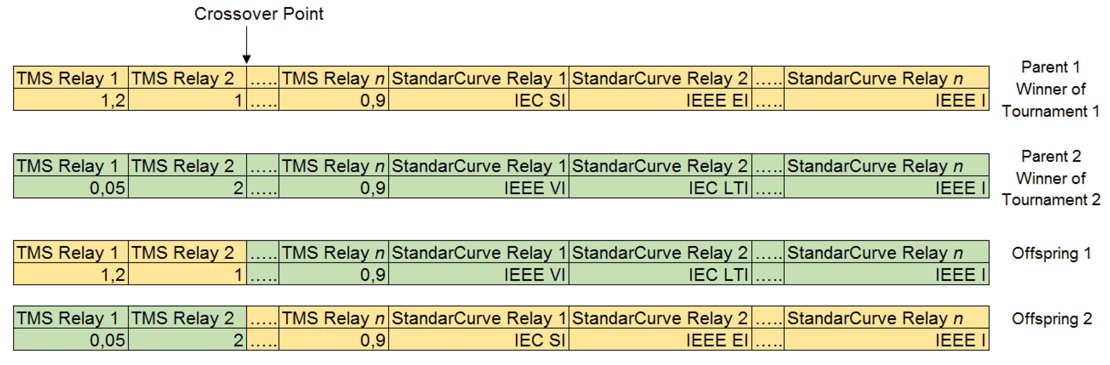
3.3. Selection and Crossover

The idea behind the selection step is guaranteeing that the fittest individuals have greater chance to pass on their genes into the next generation. In this case, a tournament selection was implemented. In every tournament, two individuals of the current population are randomly chosen and the best one is selected for the crossover stage. In this later stage, the selected individuals act as parents which exchange their information to produce new solution candidates. The crossover is performed at a random position of the vector and it is illustrated in Figure 3.

3.4. Mutation and New Generation

The mutation stage allows for the GA to eventually escape from locally optimal solutions and adds diversification to the algorithm. In this step, one of the offspring generated in the crossover is randomly selected and a small variation is performed in one of its variables. Such variation is performed within the variable limits to avoid the creation of unfeasible solutions. Figure 4 depicts an example of this state. Once the mutation process is finished, the fittest individuals are selected from the combined population of parents and offspring. In this stage, half of the individuals are discarded in order to preserve the size of the initial population. The process continues until a given number of generations is reached or until a maximum number of interactions has been evaluated without any improvement of the OF.

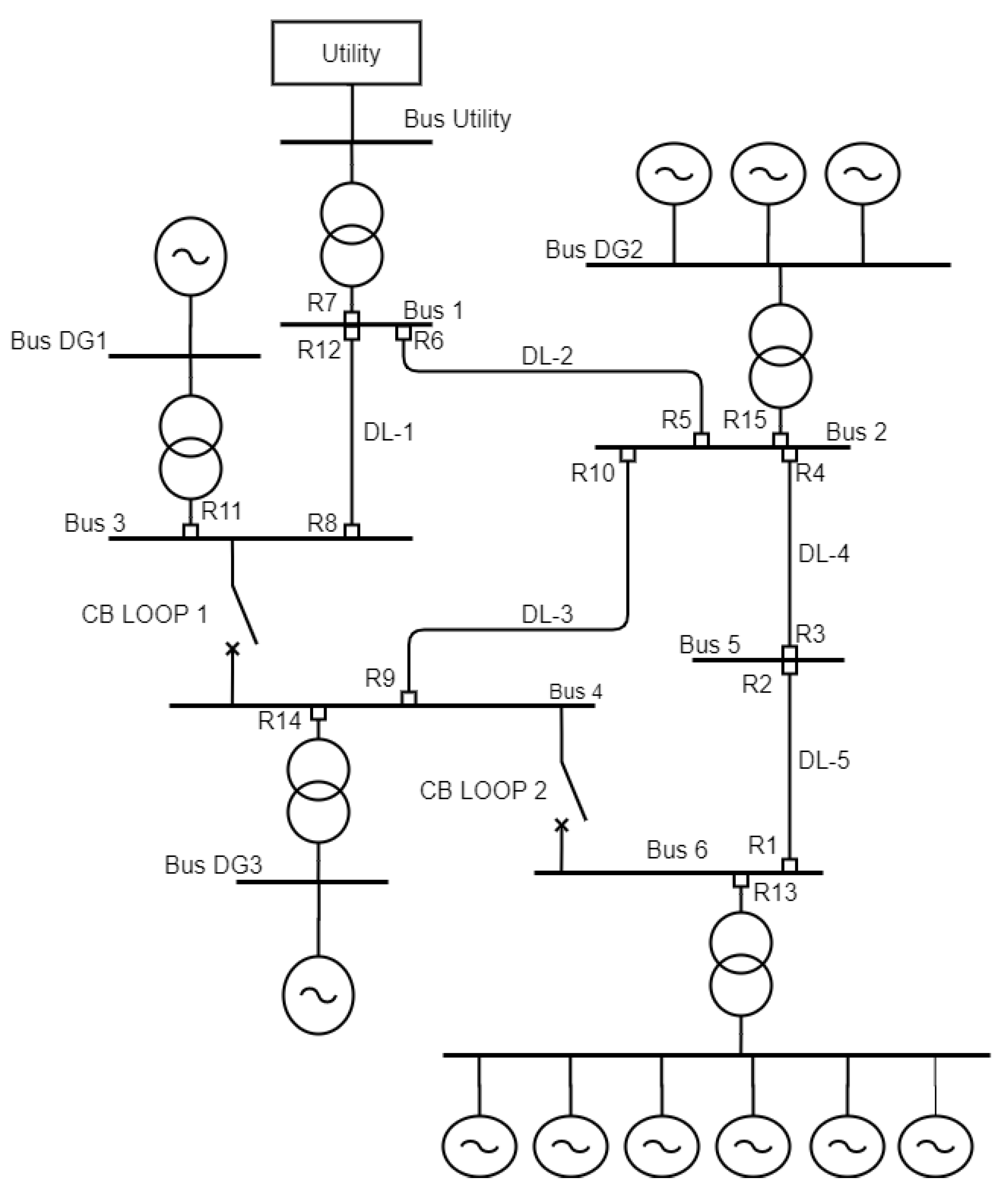
4. Tests and Results

Several tests were carried out in the benchmark IEC microgrid that is depicted in Figure 5 for showing the applicability of the proposed approach. The data of this system are available in [27]. This microgrid integrates DG and features four operational modes (OMs), as indicated in Table 2. In OM1, all DG units are off and the demand is supplied only through the main grid. In OM2, the demand can be supplied through the main grid and the DG units, since all of them are available. In OM3, DG3 and DG4 are off and the load can be supplied through the main grid as well as through DG1 and DG2, which are available. Finally, in OM4 the load is only supplied with the DG units and the microgrid operates in off-grid mode.
The test system was implemented in DIgSILENT PowerFactory when considering five three-phase line failures (F1 to F5). In this case, F1 represents a fault on line DL-5; F2 and F3 are failures on lines DL-4 and DL-2, respectively; F4 represents a fault on DL-1 line; and, F5 represents a fault on DL-3 line. All of the calculations and tests were performed in accordance with the IEEE 242 standard, which is widely used for coordination of over-current protections [28].
The results that were obtained with the proposed approach were compared with those reported in [15,16,17], adjusting their same short-circuit levels and considering their same transformation ratios of current transformers R C T and starting currents i p i c k u p , please see Table 3.
IEEE 242 Standard [28] recommends a coordination time interval of ( C T I ) of at least 0.2 s. In this work, we adopted a C T I of 0.3 s for performing a comparative analysis with [15,16,17], which use IEC normal inverses curves. The relays of the microgrid are labeled with numbers ranging from 1 to 15 preceded by the letter “R”. In this case, the letters “P” and “B” were added to the label in order to differentiate main and backup relays, respectively. Figure 5 shows the location of each relay.
After running several tests with the GA, the parameters that yield the best results correspond to a population of 100 individuals, a crossing rate of 0.7, and a mutation rate of 0.3. The maximum number of generations was set to 1000. Additionally, in all scenarios under analysis, CB-LOOP1 and CB-LOOP2 were considered to be open.

4.1. Results for OM1

In OM1, the microgrid is connected to the main supply, while all of the DG units are disconnected. Table 4 presents the results that were obtained with the proposed model and the ones reported in [15,16,17] for comparative purposes. The T M S and S t a n d a r C u r v e i are presented for each relay as well as the sum of the operating times for all relays T ( s ) , which represents the OF of the problem. Note that the proposed model obtained better operating times, which ensures coordination between main and backup OCRs. In this case, the relays presented different types of characteristic curves S t a n d a r C u r v e i . Table 5 presents the operating times of main and backup relays for each fault. In all cases, the proposed model presented lower operating times than those presented in [15,16]. For faults F1, F2, and F5, the proposed model also presents lower operating times than those presented in [17]. Nevertheless, for faults F3 and F4, the proposed approached presented slightly higher operation times when compared with [17].

4.2. Results for OM2

In OM2, the load can be supplied by both the DG units and the main grid. Table 6 presents the parameters obtained for the OCRs coordination. The T M S and S t a n d a r C u r v e i are presented for each relay as well as the sum of the operating times for all relays, denoted as T ( s ) . Note that the proposed approach considers different characteristic curves for the relays and the total operation time T ( s ) is lower than the one reported in [15,16,17] (these last ones only consider the IEC NI curve). Table 7 shows the operating times of the main and backup relays for each fault. In all cases, the proposed model presented lower operating times than those that were reported in [15,16]. When comparing with [17] the proposed model shows lower operation time for three of the five faults under consideration (F1, F2, and F5). Nevertheless, for faults F3 and F4, the operation time of the proposed approach is higher. In this case, for F3 and F4, the proposed model presented better operating times for all main relays, except for RP6 and RP8, respectively.

4.3. Results for OM3

In this operational mode, the microgrid is connected to the main supply network working together with DG1 and DG2, while DG3 and DG4 are disconnected. The OCR coordination parameters obtained with the GA are presented in Table 8. The T M S and S t a n d a r C u r v e i are presented for each relay as well as the sum of the operating times for all relays, denoted as T ( s ) . Note that different characteristic curves were adopted by the relays with the proposed approach and the operation time T ( s ) is lower than the one reported in [15,16,17], which considered a single characteristic curve S t a n d a r C u r v e i . Table 9 shows the operating times of the main and backup relays for each fault. In all cases, the proposed model presented lower operating times than the ones reported in [15]. When comparing with [16] and [17], the proposed approach was able to find better coordination times in four out of the five faults (only in F3 the coordination times were higher).

4.4. Results for OM4

In this case, the microgrid operates in islanded mode and the load is supplied by the DG units. Table 10 presents the results of the OCRs coordination obtained with the GA. As with the previous operational modes, the proposed approach presents better operating time T ( s ) when compared with the results that were reported in [15,16,17]. Table 11 shows the operating times of main and backup relays for each fault. Note that, in all cases, the proposed model presents lower operation times than those that were reported in [15,16,17].

4.5. Results Considering All Operational Modes Simultaneously

So far, a different set of coordination parameters for the OCRs has been obtained for each OM in the previous sections. However, the proposed approach can also be used to obtain a single set of coordination parameters that are suitable for all OMs. Table 12 shows the set of coordination parameters, obtained with the proposed GA, which is suitable for all OMs. The results that were obtained with the proposed approach were compared with those reported in [17]. The T M S and S t a n d a r C u r v e i are presented for each relay as well as the sum of the operating times for all relays T ( s ) for all OMs which represents the OF of the problem. Note that the proposed model was able to reach better operating times, ensuring coordination between main and backup OCRs. In this case, the relays presented different types of characteristic curves S t a n d a r C u r v e i , Table 13 presents the operation times of the main and backup relays for each fault. In this case, the coordination between main and back up relays is also guaranteed.
Table 14 presents a comparison of operation times for different OMs using multiple and a single set of coordination parameters. In this case, operation times reported in columns 2 through 5 consider an independent set of parameters for each OM. Note that, for all OMs, the proposed approach presents lower operation times (column 5). On the other hand, the operation times presented in columns 6 and 7 are computed when considering a single set of parameters suitable for all OMs. Such single set of parameters results in different operation times depending on the OM of the microgrid. As expected, obtaining a single set of coordination parameters suitable for all OMs results in higher operation times, as shown in column 7. It is worth mentioning that references [15,16] do not present a single set of coordination parameters suitable for all OMs, which does not allow a direct comparison. Despite this fact, it can be noted that the proposed approach outperforms the results of [15,16] in OM1, OM2 and OM4. Reference [17] presents a single set of coordination parameters suitable for all OMs (column 6). In this case, the proposed approach also obtains better results.

5. Conclusions

Microgrids are becoming increasingly common in modern distribution networks. Because they feature different operational modes and usually integrate DG, new approaches for protection coordination must be sought in order to guarantee network security. This paper presented an approach for the optimal coordination of over-current relays in microgrids that integrate DG. The main feature that differentiates the proposed approach from other methodologies reported in the specialized literature lies in the fact that it allows for choosing the characteristic curve used by the main and back up relays among multiple options, which results in a more flexible approach for protection coordination. Several tests were carried out with a benchmark IEC microgrid that integrates DG and features different operational modes (OMs). The results obtained with the proposed approach evidenced that considering different characteristic curves results in lower operational times of the protection coordination. In all operational modes, the proposed approach presented better operational times. In OM1, the total operating time that was obtained with the proposed approach was 4.19 s, while the best one reported so far in the specialized literature was 4.99 s, which represents a time improvement of 16%. For OM2, the total coordination time that was obtained with the proposed approach was 12.48 s against 13.66 s (the best solution reported so far), representing a time improvement of 8.6%; analogously, the coordination time reduction in OM3 was 2%. Finally, the highest total coordination time improvement was obtained for OM4 with a time reduction of 29.2% with respect to the best time reported in the specialized literature. Additionally, for almost every of the five faults under consideration, the proposed approach was able to find better operational times.

Author Contributions

Conceptualization, S.D.S.-Z. and J.M.L.-L.; Data curation, S.D.S.-Z.; Formal analysis, S.D.S.-Z., N.M.-G. and J.M.L.-L.; Funding acquisition, J.M.L.-L. and N.M.-G.; Investigation, S.D.S.-Z., N.M.-G. and J.M.L.-L.; Methodology, S.D.S.-Z.; Project administration, S.D.S.-Z., N.M.-G. and J.M.L.-L.; Resources, S.D.S.-Z., N.M.-G. and J.M.L.-L.; Software, S.D.S.-Z.; Supervision, N.M.-G. and J.M.L.-L.; Validation, S.D.S.-Z., N.M.-G. and J.M.L.-L.; Visualization, S.D.S.-Z., N.M.-G. and J.M.L.-L.; Writing—original draft, S.D.S.-Z.; Writing—review and editing, S.D.S.-Z., N.M.-G. and J.M.L.-L. All authors have read and agreed to the published version of the manuscript.

Funding

This research was funded by the Colombia Scientific Program within the framework of the so-called Ecosistema Científico (Contract No. FP44842-218-2018).

Acknowledgments

The authors gratefully acknowledge the support from the Colombia Scientific Program within the framework of the call Ecosistema Científico (Contract No. FP44842-218-2018). The authors also want to acknowledge Universidad de Antioquia for its support through the project “estrategia de sostenibilidad”.

Conflicts of Interest

The authors declare no conflict of interest.

References

  1. Henderson, M. Microgrid Controllers: Their Important Role in the System [from the Editor]. IEEE Power Energy Mag. 2017, 15, 4–6. [Google Scholar] [CrossRef]
  2. Giraldo, J.S.; Castrillon, J.A.; López, J.C.; Rider, M.J.; Castro, C.A. Microgrids energy management using robust convex programming. IEEE Trans. Smart Grid 2018, 10, 4520–4530. [Google Scholar] [CrossRef]
  3. Katyara, S.; Staszewski, L.; Leonowicz, Z. Protection Coordination of Properly Sized and Placed Distributed Generations–Methods, Applications and Future Scope. Energies 2018, 11, 2672. [Google Scholar] [CrossRef] [Green Version]
  4. Hosseini, S.A.; Abyaneh, H.A.; Sadeghi, S.H.H.; Razavi, F.; Nasiri, A. An overview of microgrid protection methods and the factors involved. Renew. Sustain. Energy Rev. 2016, 64, 174–186. [Google Scholar] [CrossRef]
  5. Telukunta, V.; Pradhan, J.; Agrawal, A.; Singh, M.; Srivani, S.G. Protection challenges under bulk penetration of renewable energy resources in power systems: A review. CSEE J. Power Energy Syst. 2017, 3, 365–379. [Google Scholar] [CrossRef]
  6. de Souza, A.C.Z.; Castilla, M. Microgrids Design and Implementation; Springer: New York, NY, USA, 2019. [Google Scholar]
  7. Gomes, M.; Coelho, P.; Moreira, C. Microgrid Protection Schemes. In Microgrids Design and Implementation; Springer: Cham, Switzerland, 2019; pp. 311–336. [Google Scholar]
  8. Kiliçkiran, H.C.; Şengör, İ.; Akdemir, H.; Kekezoğlu, B.; Erdinç, O.; Paterakis, N.G. Power system protection with digital overcurrent relays: A review of non-standard characteristics. Electr. Power Syst. Res. 2018, 164, 89–102. [Google Scholar] [CrossRef]
  9. Jaramillo Serna, J.d.J.; López-Lezama, J.M. Alternative Methodology to Calculate the Directional Characteristic Settings of Directional Overcurrent Relays in Transmission and Distribution Networks. Energies 2019, 12, 3779. [Google Scholar] [CrossRef] [Green Version]
  10. Saleh, K.A.; Zeineldin, H.H.; El-Saadany, E.F. Optimal Protection Coordination for Microgrids Considering N -1 Contingency. IEEE Trans. Ind. Inform. 2017, 13, 2270–2278. [Google Scholar] [CrossRef]
  11. Alam, M.N.; Gokaraju, R.; Chakrabarti, S. Protection coordination for networked microgrids using single and dual setting overcurrent relays. IET Gener. Transm. Distrib. 2020, 14, 2818–2828. [Google Scholar] [CrossRef]
  12. Baghaee, H.R.; Mirsalim, M.; Gharehpetian, G.B.; Talebi, H.A. MOPSO/FDMT-based Pareto-optimal solution for coordination of overcurrent relays in interconnected networks and multi-DER microgrids. IET Gener. Transm. Distrib. 2018, 12, 2871–2886. [Google Scholar] [CrossRef]
  13. Lin, H.; Sun, K.; Tan, Z.H.; Liu, C.; Guerrero, J.M.; Vasquez, J.C. Adaptive protection combined with machine learning for microgrids. IET Gener. Transm. Distrib. 2019, 13, 770–779. [Google Scholar] [CrossRef]
  14. Alam, M.N. Adaptive protection coordination scheme using numerical directional overcurrent relays. IEEE Trans. Ind. Inform. 2018, 15, 64–73. [Google Scholar] [CrossRef]
  15. Saad, S.M.; El-Naily, N.; Mohamed, F.A. A new constraint considering maximum PSM of industrial over-current relays to enhance the performance of the optimization techniques for microgrid protection schemes. Sustain. Cities Soc. 2019, 44, 445–457. [Google Scholar] [CrossRef]
  16. El-Naily, N.; Saad, S.M.; Hussein, T.; Mohamed, F.A. A novel constraint and non-standard characteristics for optimal over-current relays coordination to enhance microgrid protection scheme. IET Gener. Transm. Distrib. 2019, 13, 780–793. [Google Scholar] [CrossRef]
  17. Saldarriaga-Zuluaga, S.D.; López-Lezama, J.M.; Muñoz-Galeano, N. Optimal Coordination of Overcurrent Relays in Microgrids Considering a Non-Standard Characteristic. Energies 2020, 13, 922. [Google Scholar] [CrossRef] [Green Version]
  18. Alam, M.N. Overcurrent protection of AC microgrids using mixed characteristic curves of relays. Comput. Electr. Eng. 2019, 74, 74–88. [Google Scholar] [CrossRef]
  19. IEC. Electrical Relays-Part 3: Single Input Energizing Quantity Measuring Relays with Dependent or Independent Time; IEC 60255-3; IEC: Geneva, Switzerland, 1989. [Google Scholar]
  20. Benmouyal, G.; Meisinger, M.; Burnworth, J.; Elmore, W.A.; Freirich, K.; Kotos, P.A.; Leblanc, P.R.; Lerley, P.J.; McConnell, J.E.; Mizener, J.; et al. IEEE standard inverse-time characteristic equations for overcurrent relays. IEEE Trans. Power Deliv. 1999, 14, 868–872. [Google Scholar] [CrossRef]
  21. Wei, Z.; Zhao, J.; Ji, D.; Tseng, K.J. A multi-timescale estimator for battery state of charge and capacity dual estimation based on an online identified model. Appl. Energy 2017, 204, 1264–1274. [Google Scholar] [CrossRef]
  22. Wei, Z.; Li, X.; Xu, L.; Cheng, Y. Comparative study of computational intelligence approaches for NOx reduction of coal-fired boiler. Energy 2013, 55, 683–692. [Google Scholar] [CrossRef]
  23. Pious Akushie, U. Coordination Improvement of Directional Overcurrent Relays in a Microgrid Using Modified Particle Swarm Optimization Algorithm. Int. J. Electr. Compon. Energy Convers. 2018, 4, 21. [Google Scholar] [CrossRef]
  24. Tejeswini, M.; Raglend, I.J.; Yuvaraja, T.; Radha, B. An advanced protection coordination technique for solar in-feed distribution systems. Ain Shams Eng. J. 2019, 10, 379–388. [Google Scholar] [CrossRef]
  25. Chabanloo, R.M.; Maleki, M.G.; Agah, S.M.M.; Habashi, E.M. Comprehensive coordination of radial distribution network protection in the presence of synchronous distributed generation using fault current limiter. Int. J. Electr. Power Energy Syst. 2018, 99, 214–224. [Google Scholar] [CrossRef]
  26. Dahej, A.E.; Esmaeili, S.; Hojabri, H. Co-optimization of Protection Coordination and Power Quality in Microgrids Using Unidirectional Fault Current Limiters. IEEE Trans. Smart Grid 2017, 9, 5080–5091. [Google Scholar] [CrossRef]
  27. Kar, S.; Samantaray, S.R.; Zadeh, M.D. Data-Mining Model Based Intelligent Differential Microgrid Protection Scheme. IEEE Syst. J. 2017, 11, 1161–1169. [Google Scholar] [CrossRef]
  28. IEEE. IEEE Recommended Practice for Protection and Coordination of Industrial and Commercial Power Systems (IEEE Buff Book). In Recommended Practice for Protection and Coordination of Indusrial and Commercial Power Systems; IEEE: New York, NY, USA, 1986; pp. 1–710. [Google Scholar] [CrossRef]
Figure 1. Example of a candidate solution.
Electronics 09 01740 g001
Figure 2. Fitness evaluation.
Electronics 09 01740 g002
Figure 3. Example of crossover.
Electronics 09 01740 g003
Figure 4. Example of Mutation.
Electronics 09 01740 g004
Figure 5. Benchmark IEC micro-grid.
Electronics 09 01740 g005
Table 1. Optimal coordination of OCRs in microgrids (knowledge gap).
ReferenceMultiple ParametersSingle Set of ParametersPSM ConstraintIEC CurvesIEEE Curves
[11]-X---
[18]XX-X-
[14]X----
[12]-XX--
[10]XX---
[15,16]X-X--
[17]XXX--
[Proposed]XXXXX
Table 2. Microgrid operational modes.
Operational ModeGridDG1DG2DG3DG4
OM1onoffoffoffoff
OM2ononononon
OM3onononoffoff
OM4offonononon
Table 3. R C T and i p i c k u p for each relay.
Relay RCT i pickup
R14000.50
R24000.50
R34000.50
R44000.50
R54000.50
R64000.50
R712001.00
R84000.50
R94000.50
R104000.50
R114000.65
R124000.50
R134000.88
R144000.65
R154000.55
Table 4. Coordination parameters for OM1.
Relay TMS i (Curve) [15] TMS i (Curve) [16] TMS i (Curve) [17] TMS i (Curve) [Proposed]
R1----
R20.128 (IEC NI)0.1283 (IEC NI)0.0500 (IEC NI)0.0500 (IEC EI)
R3----
R40.256 (IEC NI)0.2591 (IEC NI)0.1787 (IEC NI)0.2306 (IEEE MI)
R5----
R60.391 (IEC NI)0.4024 (IEC NI)0.3223 (IEC NI)0.7715 (IEC STI)
R70.335 (IEC NI)0.2895 (IEC NI)0.2060 (IEC NI)0.0500 (IEEE I)
R8----
R9----
R100.1283 (IEC NI)0.1283 (IEC NI)0.0500 (IEC NI)0.0500 (IEC EI)
R11----
R120.1320 (IEC NI)0.0101 (IEC NI)0.0500 (IEC NI)0.0500 (IEC STI)
R13----
R14----
R15----
T(s)7.536.644.994.19
Table 5. Operation times for OM1.
FaultRelays[15][16][17][Proposed]
F1RP1----
RP20.290.3030.11650.0118
RB40.590.6060.41650.3117
RB13----
F2RP3----
RP40.580.540.37320.3063
RB1----
RB60.860.840.67320.6247
RB15----
F3RP5----
RP60.880.720.58190.6247
RB71.181.020.88190.9372
RB8----
RB15----
F4RP8----
RP120.290.20.10440.0405
RB5----
RB71.591.370.97861.01
RB11----
F5RP9----
RP100.290.280.11650.0118
RB60.910.880.75140.3118
RB14----
RB15----
Table 6. Coordination parameters for OM2.
Relay TMS i (Curve) [15] TMS i (Curve) [16] TMS i (Curve) [16] TMS i (Curve) [Proposed]
R10.173 (IEC NI)0.1736 (IEC NI)0.1370 (IEC NI)0.38928 (IEEE EI)
R20.132 (IEC NI)0.1391 (IEC NI)0.0500 (IEC NI)0.0500 (IEC STI)
R30.086 (IEC NI)0.0868 (IEC NI)0.0500 (IEC NI)0.0500 (IEC STI)
R40.265 (IEC NI)0.2782 (IEC NI)0.1891 (IEC NI)0.4205 (IEC STI)
R50.172 (IEC NI)0.1720 (IEC NI)0.1148 (IEC NI)0.3939 (IEEE EI)
R60.397 (IEC NI)0.4010 (IEC NI)0.3198 (IEC NI)0.8186 (IEC STI)
R70.338 (IEC NI)0.2839 (IEC NI)0.2439 (IEC NI)0.2725 (IEC SI)
R80.265 (IEC NI)0.2226 (IEC NI)0.1911 (IEC NI)0.6055 (IEEE EI)
R90.069 (IEC NI)0.0695 (IEC NI)0.0500 (IEC NI)0.0500 (IEEE SI)
R100.132 (IEC NI)0.1413 (IEC NI)0.0500 (IEC NI)0.0500 (IEC STI)
R110.280 (IEC NI)0.2437 (IEC NI)0.2175 (IEC NI)0.4523 (IEC STI)
R120.132 (IEC NI)0.1503 (IEC NI)0.0500 (IEC NI)0.0500 (IEC STI)
R130.194 (IEC NI)0.1936 (IEC NI)0.1669 (IEC NI)0.7462 (IEC STI)
R140.116 (IEC NI)0.1159 (IEC NI)0.0998 (IEC NI)0.1715 (IEEE EI)
R150.186 (IEC NI)0.1704 (IEC NI)0.1359 (IEC NI)0.2968 (IEEE MI)
T(s)19.1817.4813.6612.48
Table 7. Operation times for OM2.
FaultRelays[15][16][17][Proposed]
F1RP10.560.550.44540.2858
RP20.290.2990.10780.0405
RB40.590.590.40780.3405
RB130.860.860.74540.5858
F2RP30.290.290.17230.0302
RP40.60.520.35560.3405
RB10.590.580.47230.3301
RB60.90.820.65560.6629
RB150.890.820.65560.6406
F3RP50.450.450.30390.186
RP60.90.70.56180.6629
RB71.191.00.86180.9628
RB81.01.00.86180.9629
RB150.970.970.77750.7386
F4RP81.00.940.82290.8467
RP120.290.290.09950.0405
RB50.60.590.39950.3405
RB71.741.441.251.4
RB111.231.231.121.14
F5RP90.290.250.21520.1792
RP100.290.290.10590.0405
RB60.950.950.76680.3405
RB140.590.570.51520.4792
RB151.221.220.97550.8976
Table 8. Coordination parameters for OM3.
Relay TMS i (Curve) [15] TMS i (Curve) [16] TMS i (Curve) [17] TMS i (Curve) [Proposed]
R1----
R20.092 (IEC NI)0.092 (IEC NI)0.0500 (IEC NI)0.0500 (IEC STI)
R3----
R40.227 (IEC NI)0.227 (IEC NI)0.1855 (IEC NI)0.4205(IEC STI)
R50.087 (IEC NI)0.090 (IEC NI)0.0608 (IEC NI)0.0553 (IEEE EI)
R60.356 (IEC NI)0.362 (IEC NI)0.3232 (IEC NI)0.8408 (IEC STI)
R70.312 (IEC NI)0.264 (IEC NI)0.2027 (IEC NI)0.6669 (IEEE MI)
R80.207 (IEC NI)0.207 (IEC NI)0.1925 (IEC NI)0.6184 (IEEE EI)
R9----
R100.0847 (IEC NI)0.084 (IEC NI)0.0500 (IEC NI)0.0500 (IEC STI)
R110.2626 (IEC NI)0.231 (IEC NI)0.2186 (IEC NI)0.463 (IEC STI)
R120.1320 (IEC NI)0.145 (IEC NI)0.0500 (IEC NI)0.0500 (IEC STI)
R13----
R14----
R150.1670 (IEC NI)0.154 (IEC NI)0.1373 (IEC NI)0.2968 (IEEE MI)
T(s)14.0412.6710.7110.49
Table 9. Operation times for OM3.
FaultRelays[15][16][17][Proposed]
F1RP1----
RP20.2000.2000.11070.0405
RB40.5080.5020.41070.3405
RB13----
F2RP3----
RP40.5080.440.36250.3405
RB1----
RB60.8070.740.66250.6809
RB150.8000.730.66250.6406
F3RP50.420.420.28780.2109
RP60.800.630.56770.6809
RB71.100.930.86770.9808
RB81.100.930.86770.9808
RB150.840.780.69580.6670
F4RP81.050.890.82860.8621
RP120.290.2980.10250.0450
RB50.670.640.40250.3406
RB71.521.280.98990.1.3117
RB111.351.191.12861.1622
F5RP9----
RP100.190.190.11070.0405
RB60.830.840.75510.3405
RB14----
RB151.100.990.90300.8317
Table 10. Coordination parameters for OM4.
Relay TMS i (Curve) [15] TMS i (Curve) [16] TMS i (Curve) [17] TMS i (Curve) [Proposed]
R10.173 (IEC NI)0.1730 (IEC NI)0.1370 (IEC NI)0.3892 (IEEE EI)
R20.105 (IEC NI)0.1050 (IEC NI)0.0500 (IEC NI)0.0500 (IEC STI)
R30.086 (IEC NI)0.0860 (IEC NI)0.0500 (IEC NI)0.0500 (IEC STI)
R40.211 (IEC NI)0.2110 (IEC NI)0.1571 (IEC NI)0.5289 (IEC EI)
R50.209 (IEC NI)0.2090 (IEC NI)0.1552 (IEC NI)0.8621 (IEEE EI)
R60.181 (IEC NI)0.1812 (IEC NI)0.1510 (IEC NI)0.2426 (IEEE MI)
R7----
R80.247 (IEC NI)0.2476 (IEC NI)0.2176 (IEC NI)0,4999 (IEEE EI)
R90.069 (IEC NI)0.0695 (IEC NI)0.0500 (IEC NI)0.0500 (IEC STI)
R100.112 (IEC NI)0.1124 (IEC NI)0.0500 (IEC NI)0.0500 (IEC STI)
R110.264 (IEC NI)0.2645 (IEC NI)0.2395 (IEC NI)0.4311 (IEEE EI)
R120.104 (IEC NI)0.1050 (IEC NI)0.0500 (IEC NI)0.0500 (IEC STI)
R130.193 (IEC NI)0.1930 (IEC NI)0.1669 (IEC NI)0.1011 (IEC STI)
R140.115 (IEC NI)0.1159 (IEC NI)0.0998 (IEC NI)0.1037 (IEEE EI)
R150.177 (IEC NI)0.1771 (IEC NI)0.1476 (IEC NI)0.6299 (IEC STI)
T(s)15.5615.5612.638.96
Table 11. Operation times for OM4.
FaultRelays[15][16][17][Proposed]
F1RP10.560.560.44540.2858
RP20.290.290.14000.0244
RB40.590.590.44000.3244
RB130.860.860.74540.5858
F2RP30.290.290.17230.0302
RP40.550.550.41210.2347
RB10.590.590.47230.3301
RB60.850.850.71210.5347
RB150.850.850.71210.5347
F3RP50.550.550.41060.2626
RP60.810.810.68090.5163
RB7----
RB81.101.100.98090.8162
RB151.011.010.84470.6357
F4RP81.061.060.93670.7203
RP120.290.290.14260.0248
RB50.590.590.44260.3249
RB7----
RB111.371.371.23671.0204
F5RP90.290.290.21520.0378
RP100.290.290.13300.0231
RB61.001.000.87070.6284
RB140.590.590.51520.3379
RB151.001.000.97060.7316
Table 12. Coordination parameters considering all OMs simultaneously.
Relay TMS i (Curve) [17] TMS i (Curve) [Proposed]
R10.1371 (IEC NI)0.3892 (IEEE EI)
R20.0500 (IEC NI)0.05 (IEEE MI)
R30.0500 (IEC NI)0.05 (IEC STI)
R40.1892 (IEC NI)0.4097 (IEEE MI)
R50.1552 (IEC NI)2.4918 (IEEE SI)
R60.3007 (IEC NI)0.9756 (IEC STI)
R70.2816 (IEC NI)0.7509 (IEEE MI)
R80.3673 (IEC NI)0.697 (IEEE EI)
R90.0500 (IEC NI)0.05 (IEEE SI)
R100.0500 (IEC NI)0.05 (IEC STI)
R110.3644 (IEC NI)0.5443 (IEEE EI)
R120.0500 (IEC NI)0.05 (IEC STI)
R130.1669 (IEC NI)0.3443 (IEEE EI)
R140.0998 (IEC NI)0.5269 (IEC STI)
R150.2042 (IEC NI)0.5072 (IEEE MI)
T(s)57.2548.61
Table 13. Operation times for all operational modes (OMs) with a single set of parameters.
FaultRelaysOM1OM2OM3OM4
F1RP1-0.2858-0.2858
RP20.15690.15570.15570.1655
RB40.46530.45570.45570.5360
RB13-0.5858-0.5858
F2RP3-0.0302-0.0302
RP40.45570.45570.45570.5093
RB1-0.3301-0.3301
RB60.79000.790.790.8093
RB15-0.1.01381.01381.0138
F3RP5-0.29110.75890.2911
RP60.790.790.79000.7733
RB71.091.091.09-
RB8-1.091.091.0900
RB15-1.18131.05901.1813
F4RP8-0.95630.95630.9563
RP120.04050.04050.04050.0248
RB5-0.53971.31790.3249
RB71.42571.54031.4626-
RB11-1.25631.25631.2563
F5RP9-0.1792-0.1792
RP100.02020.04050.04050.0231
RB60.39420.40580.39510.9921
RB14-0.4792-0.4792
RB15-1.45311.34051.3405
Table 14. Total operation time for each OM.
Multiple ParametersSingle Set of Parameters
Operational Modes T ( s ) [15] T ( s ) [16] T ( s ) [17] T ( s ) [Proposed] T ( s ) [17] T ( s ) [Proposed]
OM17.536.644.994.195.595.62
OM219.1817.4813.6612.5817.8815.34
OM314.0412.6710.7110.4915.8114.46
OM415.5615.5612.638.9617.9713.17
Publisher’s Note: MDPI stays neutral with regard to jurisdictional claims in published maps and institutional affiliations.

