1. Introduction
Illumination trends have seen a move from incandescent bulbs and fluorescent lamps to LEDs due to their advantages over conventional illumination methods, such as their high power efficiency, long life time, and fast response time. Among these advantages of LEDs, their fast response characteristic makes their use possible not only for illumination, but also for wireless communication. Visible light communication (VLC), which is also called nm-wave communication, is a communication technology that uses visible light spectra from 380 to 740 nm as information carriers [
1].
VLC has several advantages over conventional radio frequency (RF) wireless communication. Firstly, VLC has a huge unlicensed bandwidth of about 400 THz. Because most RF spectra below 10 GHz have been already used for many purposes, wireless communication engineers are trying to use higher frequencies over 10 GHz. Thus, it is expected that VLC may be used in the near future because the VLC spectrum is an extension of the trend of using higher frequencies. Secondly, VLC can be easily realized using the existing LEDs already deployed in buildings for lighting purposes by simply adding a micro controller. As each LED can work as an access point (AP), VLC could be one of the key technologies for Internet of Things (IoT) or massive machine-type communication (mMTC), since multiple Aps and a large bandwidth are required for IoT to connect numerous devices with one another. Thirdly, VLC uses visible light as the carrier frequency, which does not cause electro-magnetic interference (EMI) with other electronic devices in contrast to the conventional RF communication. Fourthly, high-speed communication links over 10 Gb/s can be easily set through the VLC link [
2]. Thanks to its advantages, research studies on VLC have been widely conducted, including for the IEEE 802.15.7 VLC standard [
3]. Comparative research of optical wireless communication (OWC) technologies is conducted in [
4]. VLC based on space-division multiple access (SDMA) [
5], software-defined radio (SDR) [
6], a light-to-frequency converter [
7], and an indoor positioning system (IPS) using VLC is studied in [
8]. A full-duplex vehicular VLC system and cooperative VLC system with full-duplex relaying is studied in [
9,
10].
However, in reality, VLC has not been widely commercialized yet. We think that one of the main reasons is its insufficient commercialization strategies. In [
11], IPS based on VLC was suggested as the first step of a VLC commercialization method, since IPS can achieve functionality without adding additional hardware in mobile devices. However, IPS based on VLC still requires additional optical receivers, such as photodiodes or image sensors. As another commercialization strategy of VLC, we suggest LED-to-LED VLC technology. LED-to-LED VLC is a VLC technique that uses LEDs as both the transmitter and receiver [
12,
13,
14,
15]. Because many devices such as smart phones or traffic lights already have built-in LED lamps, LED-to-LED VLC does not require additional optical devices for data transmission and reception in VLC links. Thus, it is expected that technologies such as IPS and mMTC could be easily realized through an LED-to-LED VLC scheme due to their low-complexity, low cost, and ease of implementation. We believe that LED-to-LED VLC will contribute to the wide spread of VLC.
To our knowledge, there have been only a few research studies on LED-to-LED VLC so far. In [
12], a LED-to-LED VLC system using colored LEDs is proposed and a related networking protocol was shown. In [
13], various usage cases of VLC are introduced, such as smartphone-to-LED, LED-to-smartphone, and LED-to-LED. In [
14], a LED-to-LED VLC with software-based synchronization using microcontroller is introduced. In [
15], the link performance of a half-duplex LED-to-LED VLC is shown by our research team. The frequency response of the receiver LED depending on the types of receiver circuits is also shown. However, the performance dependency on the wavelengths of a transmitter and a receiver LED has not been studied in detail in the previous studies.
Therefore, in this study, we investigate the performance dependency on the wavelengths of a transmitter and a receiver LED, by measuring the rise time and signal-to-noise ratio (SNR) with respect to the color of transmitter and receiver LEDs. Through the investigation, the optimal color set for a transmitter LED and a receiver LED is chosen. With the optimal LED color set, a full-duplex VLC is experimentally demonstrated with a direct-current-biased optical orthogonal frequency division multiplexing (DCO-OFDM) modulation scheme. Furthermore, we discuss distortions and signal losses in the full-duplex LED-to-LED VLC system.
3. Receiver Characteristics of LED
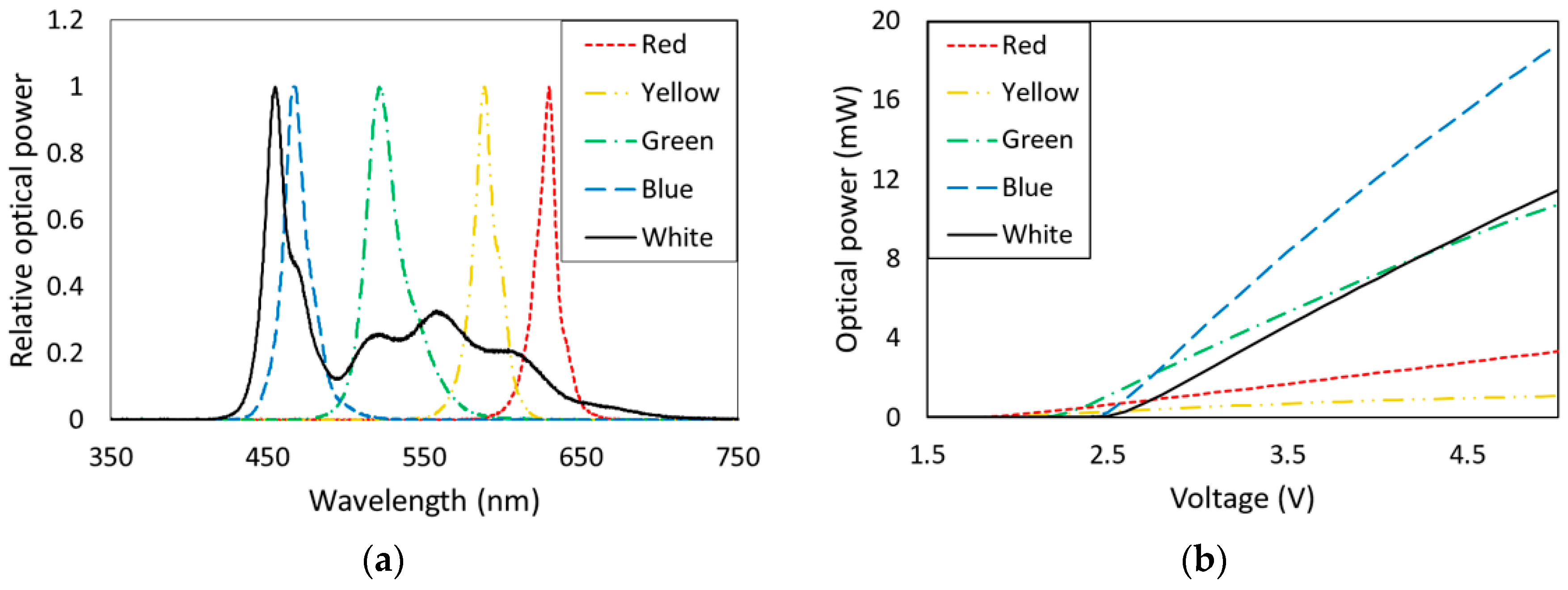
In our experiment, we used HB10P red, yellow, green, blue, and white LEDs (Yinhui photoelectric). The size and viewing angle of the LEDs were 10
(mm) and 30°, respectively. To obtain more detailed characteristics of the LEDs, we measured their spectra and optical powers. The measurement results are shown in
Figure 1 and the parameters are summarized in
Table 1. The peak wavelengths for red, yellow, green, blue, and white LEDs were measured as 628, 587, 520, 465, and 454 nm, respectively. Note that the white LED was a phosphor-converted white LED (pc-WLED).
Shannon’s channel capacity law is one of the powerful tools used to estimate the link performance when the channel bandwidth, average signal power, and average noise power are given. The channel capacity equation is given by:
where
is the capacity of the channel,
is the 3 dB bandwidth of the channel,
is the signal power, and
is the noise power.
For a simple low-pass resistor capacitor (RC) network, the step response of the system is given by:
where
is an RC time constant. The time that the signal takes to achieve
of the voltage level can be obtained by solving Equation (2):
Thus, the rise time
can be expressed as:
Since the 3 dB bandwidth of the low-pass RC system is given by
using Equations (4) and (5), the 3 dB bandwidth of a system can be approximated by the rise time of the received signal as:
Therefore, with Equations (1) and (6), we can derive another channel capacity equation:
Using Equation (7), the approximated channel capacity of each LED color set (a transmitter and receiver LED set) can be calculated by the rise time, average signal power, and average noise power of the received signal.
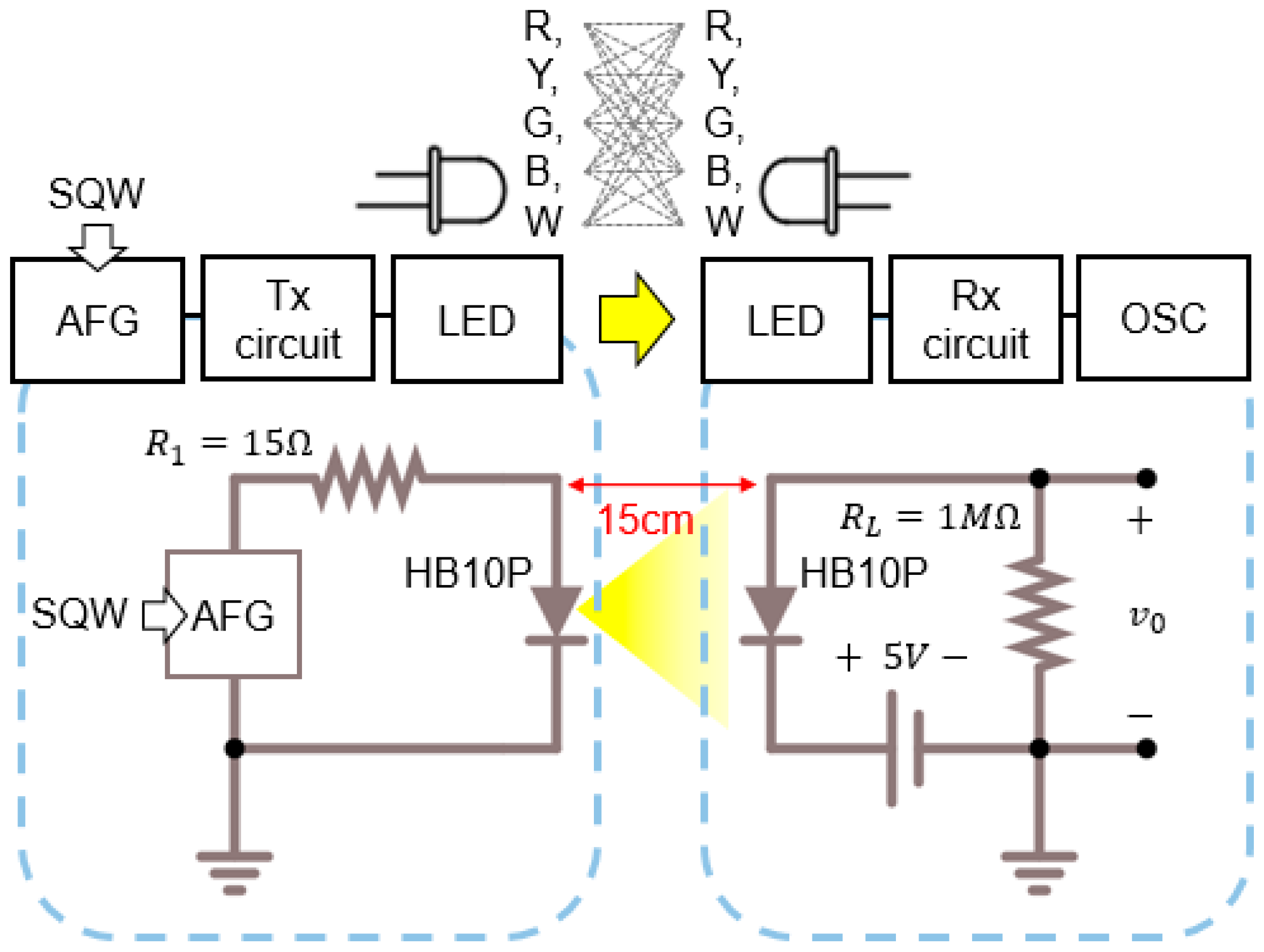
Figure 2 shows the experimental setup for measuring the rise time and SNR for all of the possible combinations of color LED transmitters and color LED receivers. On the transmitter side, a square wave (SQW) is used to modulate the transmitter LED. A serial resistance of 15 Ω is used in the transmitter circuit for circuit protection purposes. The frequency rate is 100 Hz and the transmission distance is 15 cm. The optical signal is accepted through a receiver LED with a reverse bias of 5 V and a load resistance of 1 MΩ. The electrical signal on the load resistance was measured by an oscilloscope (OSC). The rise time of the electrical signal is measured from 10% to 90% of the leading edge of the received signal.
Table 2 shows the experimental results of the rise time and SNR according to the pairs of transmitter and receiver LEDs. In addition, the channel capacities calculated by Equation (7) with the results for the rise time and SNR are shown in
Table 3. Note that the three best performing cases in each experimental result are underlined in
Table 2 and
Table 3. Additionally, the transmitter LED to pc-white LED case was not considered to avoid confusion, since pc-white LEDs are not appropriate receivers. In [
15], a half-duplex LED-to-LED VLC performance study was conducted using a blue-to-green set, since the blue-to-green set showed the best received signal amplitude value, which is the same as our SNR results in
Table 2.
However, the blue-to-green set is not the best case because its rise time is slow. The estimated channel capacity of blue-to-green set is 38.5 kbps, as shown in
Table 3. According to
Table 3, rather than the blue-to-green, instead the green-to-yellow set shows the best capacity of 59.1 kbps, which is 53% better than the blue-to-green set. Thus, the green-to-yellow set was chosen as the best color set for LED-to-LED VLC systems in our experiment.
4. Full-Duplex LED-to-LED VLC
In previous studies, several modulation schemes have been studied for optical wireless communication. On–off keying (OOK) is the simplest and most conventional modulation method in optical communication, which has the advantages of low complexity and adequate bandwidth achievement. Pulse position modulation (PPM) is suggested in the IEEE 802.15.7 VLC standard for dimming support. PPM is another modulation scheme that can achieve higher power efficiency than OOK. However, PPM requires more complicated systems and bandwidth consumption [
16]. Orthogonal frequency division multiplexing (OFDM) is a multi-carrier modulation scheme that shows high frequency efficiency. OFDM also makes systems robust to the low-frequency ambient light from other lighting sources by sending data via high-frequency subcarriers. In order to overcome the disadvantage of the low-data-rate and vulnerability to other lighting sources in LED-to-LED VLC, quadrature amplitude modulation (QAM) and DCO-OFDM are applied in our full-duplex LED-to-LED VLC experiment.
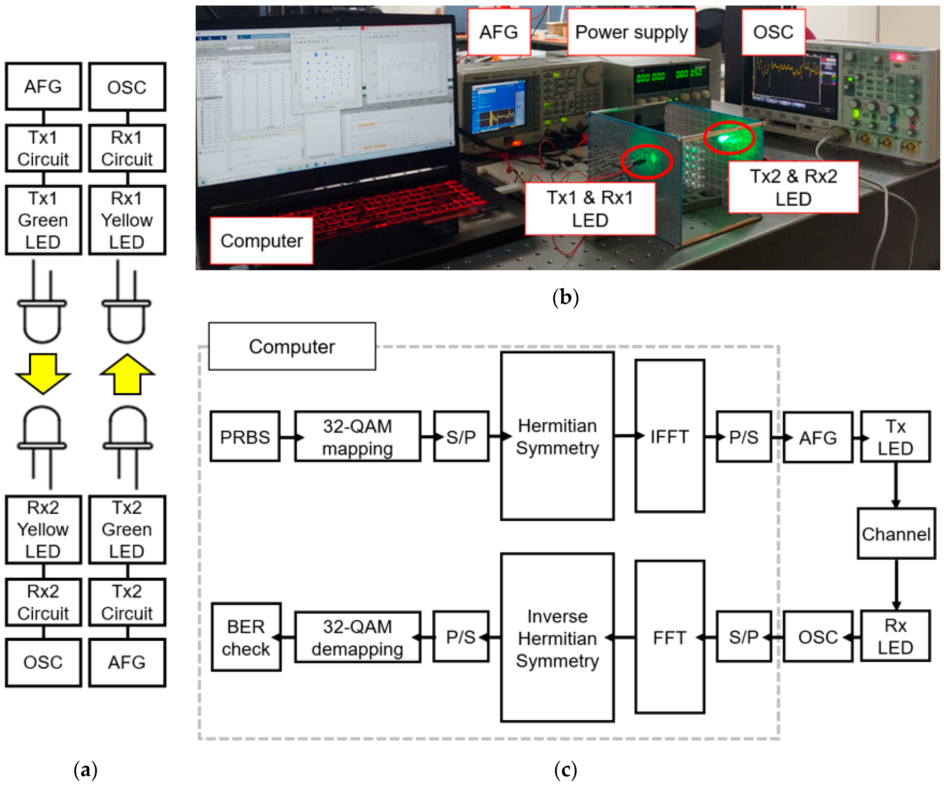
Figure 3 shows the experimental setup for the full-duplex LED-to-LED VLC link. A pseudo random binary sequence (PRBS) VLC signal is encoded with a 32-QAM and DCO-OFDM scheme. Hermitian symmetry input is used before the inverse fast Fourier transform (IFFT) process to generate a real and unipolar OFDM signal for an intensity modulation and direct detecting (IM/DD) system [
17]. Then, the OFDM signal is directly modulated with an arbitrary function generator (AFG) and sent to a green transmitter LED. The VLC signal emitted by the green transmitter LED is detected by the yellow receiver LED. The received signal is recovered with a fast Fourier transform (FFT), inverse Hermitian symmetry, and 32-QAM de-mapping process. The transmitter and receiver circuits are shown in
Figure 2. The DCO-OFDM modulated signal has an amplitude of 0.3 V and an offset of 2.9 V.
The single-sided bandwidth of a subcarrier
in our full-duplex LED-to-LED VLC system can be calculated as:
where
is the symbol time duration. The data rate of this system
is:
where
is the size of FFT and
M is the size of constellation. In our experiment, an FFT size of 100 and a constellation size of 32 are used. The experimental conditions are summarized in
Table 4.
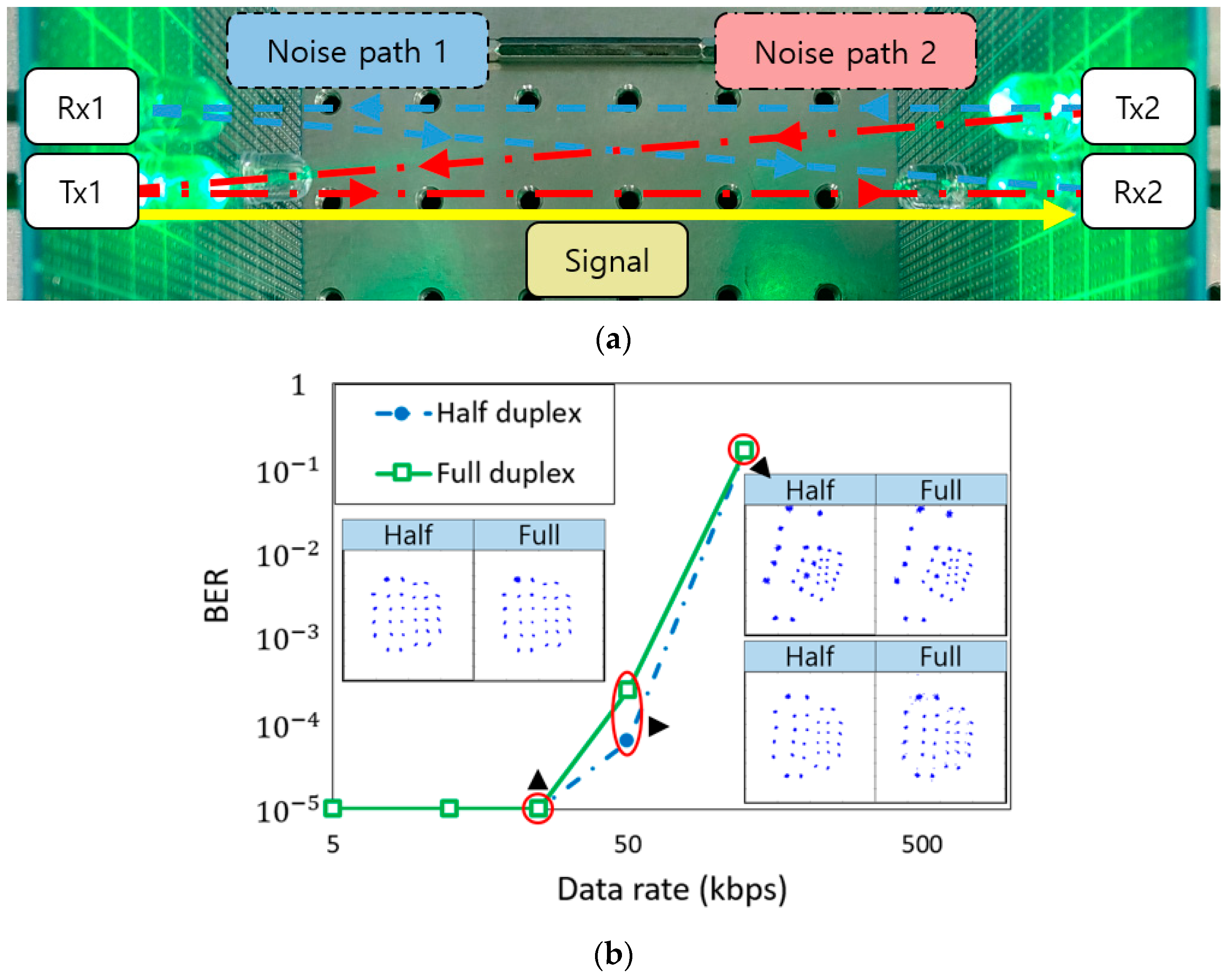
Figure 4a shows the interference path and signal path in the experimental setup, while
Figure 4b shows the bit error rate (BER) results of the half-duplex and the full-duplex LED-to-LED VLC. The received 32-QAM constellations are also shown in
Figure 4b. At data rates of 4.9, 12.25, and 24.5 kbps, the BER results are under
for both the half- and full-duplex systems. When the data rate is 49 kbps, the BERs of the half- and full-duplex systems are
and
, respectively. When the data rate is 122.5 kbps, the BERs of the half- and full-duplex systems are
and
, respectively. Note that the reason why we only considered a few bit rates (i.e., 4.9, 12.25, 24.5, 49, and 122.5 kbps) in the experiment is that those bit rates showed the optimum sample rates in the experimental equipment.
These experimental results show that both half- and full-duplex LED-to-LED VLC systems with a data rate of 49 kbps can be implemented, assuming the maximum allowable BER threshold is
. Additionally, our system shows a channel capacity value similar to that of Shannon’s channel capacity. The results also show that the performance of the half-duplex case is slightly better than the full-duplex case. We think that the reason for the performance difference is that the light emitted from the Tx2 LED is reflected at the surface of the Tx1 and Rx1 LED, then the Rx2 receives the reflected signal, as shown in
Figure 4a. Based on this, we analyzed the interference effect mathematically.
The luminous intensity of a transmitter LED at an irradiance angle of
is given by:
where
is the center luminous intensity of the LED and
is the Lambertian radiation pattern [
18]. Analytic expression for the SNR of the half-duplex system is derived as:
where
is the responsivity of the receiver LED,
d is the transmit distance,
is the radius of the LED,
is the reflectance of the fused silica (pure glass) at a wavelength of 589 nm, and
is the measured average ambient noise power in the receiver LED. The analytic expression for the SNR of the full-duplex system is derived as:
where
is the distance between Rx 1 and Tx 1 LEDs and for Rx 2 and Tx2 LEDs. The values for each parameter are listed in
Table 5. As shown in
Figure 5, the analytic results and experimental results give similar curves. Thus, we can conclude that the interference mostly occurs due to the noise path shown in
Figure 4a. As a result, it seems that slight performance degradation in the full-duplex system is caused by the reflection of the opposite LEDs.
Since the transmission distance in our system was short, the optical signal power was much stronger than the ambient background light. Thus, the effect of ambient light from other lights can be ignored in our experimental results. Therefore, we think that the main reason for the signal degradation is the reflection of opposite LEDs.
As shown in our results, the LED-to-LED VLC system has a few limitations, such as its low data rate and short transmission distance. However, we think that a higher data rate and longer transmission distance can be achieved with advanced detection techniques (e.g., artificial neural-network-based detection and optimally weighted non-coherent detection) [
19,
20].
In LED-to-PD VLC such as in [
21], the data rate is much higher than for LED-to-LED VLC. The PD used in [
21] (a New Focus 1601FS-AC instrument) had a rise time value of 400 ps and a peak responsivity value of 0.5 A/W. In contrast, our LED-to-LED VLC system achieved a maximum data rate of about 50 kbps, because the receiver LED had a rise time value of 44 μs and a peak responsivity value of 0.56 mA/W. It is obvious that PDs shows much better performance than LEDs as optical receivers. However, we believe that LED-to-LED VLC can be commercialized because it has several advantages, such as its low complexity and low cost.


