Abstract
As a newly proposed high resolution computational imaging technique, Microwave Staring Correlated Imaging (MSCI) requires elaborate design of the temporal-spatial stochastic radiation fields (TSSRF). Conventional implementation of MSCI radiation source consists of multiple transmitters configuration and simultaneous emitting scheme, which remains underutilization of the available design resources. In this paper, a time-division MSCI (TD-MSCI) method is proposed to virtually generate the TSSRF and make further use of the available design resources. Different from convention simultaneously transmitting based MSCI, the detection scheme in TD-MSCI is achieved by alternately transmitting of each transmitter, rather than simultaneous transmission of multiple transmitters. Echo enhancement is conducted to improve the SNR level of the echo waveform and to resolve the power coastdown caused by single transmitting scheme. Unused combinations of existing resources are digitally synthesized in computer rather than taking extra observations in actual physical environment. After the processing of time division observation, echo enhancement and digital waveform synthesis, extending TSSRF with better stochastic characteristics are generated, and improved imaging performance is obtained. Numerical imaging experiments and preliminary real-world imaging experiment verify the effectiveness of the proposed TD-MSCI, demonstrating that the proposed method increases the flexibility in radiation source design and decreases the detection costs.
1. Introduction
Inspired by optical Ghost Imaging (GI) [1,2], Microwave Staring Correlated Imaging (MSCI) is a newly proposed high resolution microwave computational imaging technique, where the radar system is usually carried on a stationary or quasi-stationary platform [3,4]. The essential principle of MSCI is to construct the temporal-spatial stochastic radiation fields (TSSRF), which possess stochastic characteristics both in spatial distribution and time domain. By the correlation process between scattering echo and the pre-designed radiation fields, targets within antenna beam can be reconstructed with higher resolution than the Real Aperture Radar (RAR). Previous research has indicated that, MSCI achieves superior imaging performance in staring observation applications and thus has attracted increasing attention in many aspects [5,6,7,8].
The imaging resolution of MSCI is mainly determined by the stochastic characteristics of TSSRF, or the property of the imaging matrix. By illuminating the imaging region with temporal-spatial stochastic radiation fields, neighboring scattering centers within the beam are marked by the diverse radiation field. Scattering echoes from targets at different positions in the imaging region possess diverse temporal characteristics, providing the possibility of targets decoupling. To implement the pre-designed TSSRF in the region of interest, a multi-transmitters architecture where multiple transmitters simultaneously emit randomly modulated waveforms is commonly adopted in MSCI, which requires elaborate designs of the Random Radiation Source (RRS). The literature demonstrated progress on the following two main aspects in RRS design—the stochastic multi-channel waveform design and the transmitting array design.
In waveform design, considering practical engineering limitations in actual radar systems such as bandwidth limitation and maximum output power limitation, randomly modulated waveforms, rather than ideal white noise signals, are adopted in MSCI, such as random amplitude modulated signals, random phase modulated signals, random frequency hopping signals, and so forth [9,10,11,12]. Among the above mentioned randomly modulated waveforms, random Frequency Hopping (FH) signal is most commonly employed because of its constant-envelope feature and frequency agility, which makes FH signal practical and manageable in MSCI systems. An optimization algorithm was adopted to acquire a well-behaved frequency code design of the FH signals based on minimizing the condition number of the imaging matrix [13]. In addition to waveform design, optimizing the design of the transmitting array also contributes to improving stochastic characteristic of TSSRF. Temporal–Spatial Distribution Entropy (TSDE) was proposed in Reference [14] as the optimization target of the array configuration design. A novel bi-static MSCI architecture was presented in Reference [15] to observe the targets from larger aspect angles and to form TSSRF with better stochastic features. Owing to the abundant designs of MSCI radiation source, well behaved TSSRF are generated in the imaging region and targets are reconstructed with high resolution.
However, though opitimization methods on stochastic waveform design and transmitting array design can be used to improve the property of the TSSRF and the imaging matrix, some defects are also introduced into MSCI by the simultaneous emitting scheme at the same time. The TSSRF are physically generated in the imaging region based on simultaneous transmitting of multiple transmitters, and should be accurately estimated and computed in the correlated processing according to pre-designed parameters of the system. On one hand, simultaneous transmitting scheme requires high time precision during the observation procedure in MSCI, especially the multichannel synchronization. The diverse parameters applied to different transmitters represent individual control of each transmitter, which strikingly increases the system cost and system complexity. On the other hand, once the design of radiation source is optimized, for example, the array configurations and waveform parameters such as hopping frequency sequences in random FH based MSCI are optimized, the TSSRF are hence determined. The physically superposed radiation fields cannot be directly split into individual electromagnetic fields radiated from each single transmitter. Thus the property of the imaging matrix and the imaging performance is pre-determined by the pre-designed radiation sources, and new patterns of TSSRF require extra observation cost, even when rearranging the utilized design parameters. Thus the fixed source design leaves out quite a number of unutilized resources, representing that the available design resources are underutilized.
In this paper, we propose a Time-Division MSCI (TD-MSCI) method to “virtually”, rather than physically generate the TSSRF, and make further use of the available resources in radiation source design. Different from conventional MSCI where all transmitters simultaneously radiate electromagnetic waves, the proposed TD-MSCI utilizes an alternate time-division observation scheme of each single transmitter to detect the imaging targets. Considering that the time division scheme of alternate single transmission obviously leads to power coastdown compared with simultaneous emitting scheme of multiple transmitters, which worsens the Signal to Noise Ratio (SNR) and shortens the radar detecting range, echo enhancement is proposed to improve the SNR of the scattering echo and approximately approach the actual SNR levels in multiple transmitters based MSCI. After flexibly rearranging and recombining the radiation fields, the feasible TSSRF are virtually generated and extended. The scattering echoes should also be reorganized according to the extending strategy of the TSSRF. The rearrangement of radiation fields and the corresponding echoes form the digital waveform synthesis procedure. Finally, correlated processing of the extending TSSRF with corresponding echoes is conducted to obtain well-behaved imaging performance with simplified system architecture.
The rest of the paper is organized as follows. The formulation of MSCI is demonstrated in Section 2, and the imaging performance based on matrix perturbation theory is illustrated as well. In Section 3, the procedures of TD-MSCI are proposed. In Section 4, numerical imaging experiments are with random FH waveforms, and microwave anechoic chamber imaging experiment are conducted to verify the effectiveness of the proposed TD-MSCI method. Finally, the paper is concluded in Section 5.
2. Formulation and Imaging Performance of MSCI
A typical geometry of MSCI including N transmitters and a single receiver is illustrated in Figure 1. The transmitting antennas are within a planar array located at a stationary platform. P is an arbitrary point in the 2-D imaging region S. , , and are the position vectors of the receiver, the n-th transmitting antenna, and the arbitrary point P, respectively. The RRS generates M pulses by simultaneous transmission of all the N transmitters, and temporal transient scattering echo is acquired by the single receiver. As a computational imaging technique, the imaging process of MSCI is to solve the backscattering coefficient from the imaging equation, which is formed by selecting out M TSSRF from the M pulses, meaning an independent observation is made by each pulse. The radiation fields in the imaging region are computed from predesigned parameters of RRS. By the correlated processing of calculated radiation fields and corresponding echo signals, the target within the imaging region is reconstructed via solving the imaging equation.
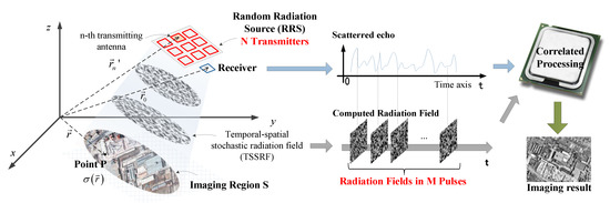
Figure 1.
A typical geometry and basic process of Microwave Staring Correlated Imaging (MSCI).
Pulse signals are commonly adopted as the excitations of the RRS. The excitation signal of the m-th pulse to the n-th transmitting antenna has the following form as
where is the rectangular window function, M is the number of pulses, is the pulse repetion interval, and T is the pulse width. are the amplitude, frequency and phase of the excitation signal to the n-th transmitting antenna in the m-th pulse, respectively, as shown in Figure 2.
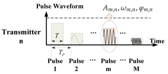
Figure 2.
Excitation Waveforms of the n-th transmitter.
The stochastic waveform design is to use random or optimized sequences as the above mentioned signal parameters, including amplitudes, frequencies, phases, and so forth. Based on the Huygens’ principle, the radiation field on the imaging region S in simultaneously emitting situation can be derived from wave equation as
where denotes the radiation pattern of the n-th antenna under frequency , and c is the speed of light. Herein, an assumption is made that the radiation patterns of the transmitting antennas are frequency independent in the available frequency bandwidth, that is, , and the mutual coupling between neighbouring antennas is ignored.
Let denote the backscattering coefficient of the target in S. The received echo from receiving antenna located at can be expressed as
where
Equation (3) is the imaging equation of integral form. The imaging process of MSCI is to solve the backscattering coefficient from the imaging equation. For numerical computation, discretize (3) by gridding the imaging region S into grids and by taking detection samples in the predesigned M pulses in time domain. Considering the effect of additive noise, the matrix-form imaging equation is derived as
where
The matrix is called the imaging matrix or sensing matrix. Based on the objective of minimizing imaging error, the scattering coefficient can be reconstructed by solving inverse problem (5) with Least Square (LS) method, described as
In noise free situation, a full-column rank imaging matrix contributes to accurate reconstruction of , that is, , which requires potentially. The square matrix is thus invertible and the target can be accurately reconstructed under noise free condition. The accurate reconstruction of the imaging target means the resolution of MSCI achieves the grid size in the imaging region S.
Then under noise condition, the imaging performance, measured by relative imaging error (RIE), satisfies the following inequality according to norm compatibility as
where is the condition number of , is -norm of vector , and approximately equals to SNR.
3. Time-Division Scheme of MSCI
In conventional multi-transmitters based MSCI where simultaneously emitted randomly modulated waveforms are adopted, parameters of radiation source refer to the amplitudes, frequencies, phases and antenna locations involved in the imaging matrix . After optimization designs of the above parameters, a family of pre-designed stochastic radiation fields is thus determined and generated. The actual radiation field in the imaging region is the linear superposition of individual radiation fields from each single transmitting antenna according to electromagnetic field theory.
However, there remains an underutilization of the available design scope. For example, as shown in the left part of Figure 3, a random FH based MSCI with N transmitters is considered. The available bandwidth is . The multiple transmitters utilize different frequencies within each pulse duration time. The optimized frequency hopping sequences of M pulses are illustrated as the frequency hopping code matrix. If the available frequencies of each transmitter is K, then the total amount of radiation fields is . For example, for a MSCI system consisting of 10 transmitters with 1000 available frequencies, the amount of radiation fields is . But only M optimized frequency arrangements are selected and utilized. Considering observation time limitations in practical radar systems, M is far less than the exponential term , thus a huge number of available frequencies remains unused. Meanwhile, considering the radiation fields are computed based on precise estimations of the transmitting parameters, in simultaneously emitting based MSCI, the multiple transmitters requires high performance of multichannel consistency and multichannel synchronization, and the unused frequency hopping codes require extra observations to be physically accomplished, which increases the system complexity and detecting cost.
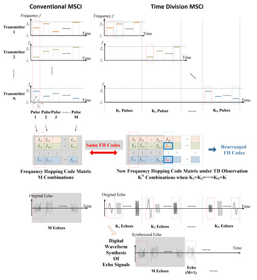
Figure 3.
Comparison of random frequency hopping MSCI and time division MSCI.
Notice that the imaging matrix can be regarded as the superposition of individual sensing matrices generated by corresponding single transmitters, namely according to (4) and (6), where
According to matrix theory, the rank of the imaging matrix satisfies
where denotes partitioned matrix consisting of , .
Therefore, when the imaging matrix is full column rank, namely , the division and recombination of the imaging matrix forms a new full column rank matrix , which satisfies . The physical meaning of the partitioned matrix is that the targets are illuminated by individual single transmitters alternately with the same design parameters in simultaneously emitting scheme, which can be regarded as a time-division observation, as demonstrated in the right part of Figure 3. The full rank property of the modified imaging matrix means that the time-division observation maintains the same resolution as simultaneously emitting MSCI.
However, the only time-division scheme will defect the imaging performance in noise condition according to (8). On one hand, the output power of each transmitter in real radar system is limited to a maximum value. The time-division observation requires alternately transmitting, which significantly reduces the total output power compared with multi-transmitters. The SNR is hence getting worse with the same receiver and noise level. On the other hand, the radiation fields generated from individual transmitter are spatially similar, thus the stochastic characteristic of TSSRF is worsened at the same time, leading to increasing condition number of the imaging matrix and underperforming imaging result. In consequence, echo enhancement and waveform synthesis are necessary steps when applying time-division MSCI and make further use of obtained observations. Therefore, the procedures of the proposed TD-MSCI are illustrated and compared with conventional MSCI method in Figure 4.
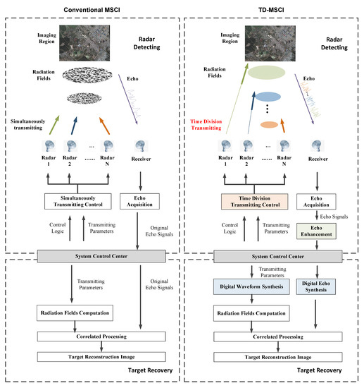
Figure 4.
Procedures of the proposed Time-Division MSCI (TD-MSCI), compared with conventional simultaneously transmitting based MSCI.
3.1. Time Division Observation
A practical time division observation scheme is to directly and physically separate the optimized designs of multiple transmitters, and transmit electromagnetic waves alternately and separately with the predefined parameters of each transmitting channel. The time division scheme can also be implemented via single transmitting channel with changing positions, which significantly decreases the system complexity and control logic, and reduces the demand for multichannel synchronization and the sources of time errors in TD-MSCI.
The superposition principle in electromagnetic field theory guarantees the feasibility of generating radiation fields with observations. Besides the utilized designs, there exists huge numbers of available but unused design resources, such as unused frequencies and waveforms. The unused design resources can enlarge the number K of basic observations under alternately transmitting scheme.
3.2. Echo Enhancement
The SNR is obviously worsened in single transmitting case compared with multiple transmitting scheme. To remedy the defect caused by power coastdown, some preprocessing methods should be applied to enhance the SNR of the scattering echo. Considering that the echo of each transmitter is time-harmonic, linear phase digital filters with corresponding narrow-band can be utilized.
Another effective way is coherent integration. By reproducing the given design of each transmitter in Q times, the SNR is enhanced to the Q times of its original value after coherent integration [16].
3.3. Digital Waveform Synthesis
With the abundant basic observations from individual transmitters, digital waveform synthesis should be considered to enhance the stochastic characteristic of TSSRF and decrease the condition number of the digitally synthesized imaging matrix. The digital waveform synthesis procedure includes the rearrangement of the transmitting waveforms, together with the corresponding operations to the relative scattering echoes, as shown in Figure 4. Besides the predesigned and utilized optimization parameters in simultaneous transmitting scheme, some digital waveform synthesis strategies include:
- (1)
- Different combinations of the utilized design resources in simultaneous transmitting scheme. For example, as shown in random FH MSCI in Figure 3, the total optimized frequency sequences of all the M pulses include . Then the frequency combination of the pulse can be , where are arbitrary positive integers from and are not exactly equal to the same value m. Hence an rearranged combination of existing frequencies is generated.
- (2)
- Rearrangement based on aforementioned utilized design resources together with uninvolved parameters, such as unused frequencies or new waveforms of each transmitting channel.
- (3)
- New kind of random modulation waveforms, for example apply random initial phases and random amplitude adjustments to random frequency hopping waveforms.
- (4)
- Re-optimized imaging matrix based on objective functions such as minimizing condition number with maintained full rank property.
Based on the diversified synthesis methods, the available design resources can be better utilized, with more abundant digitally synthesized TSSRF and better stochastic characteristics within a simplified system architecture.
3.4. Target Reconstruction
Calculate the radiation fields and solve the imaging Equation (5) to reconstruct the target within the imaging region from (7) or other imaging algorithms, such as Matched Filtering method (MF) [11], Tikhonov Regularization method [17,18], and Total Variation regularization method (TV) [19,20], and so forth.
4. Results and Discussion
To verify the effectiveness of the proposed TD-MSCI method, numerical imaging experiments with random frequency hopping waveforms and microwave anechoic chamber imaging experiment are conducted.
4.1. Comparison Experiment with the Same Frequency Hopping Sequences
To verify the effectiveness of TD-MSCI that comparable imaging performance to conventional simultaneous emitting based MSCI method is achievable with the proposed method, a comparison experiment with the same frequency hopping sequences is conducted. The geometry parameters are listed in Table 1. Optimized frequency hopping sequences are selected out to implement MSCI and TD-MSCI, where the available frequencies of each transmitter are stepped frequencies in the frequency band with step size 1 MHz, that is, 1000 available frequencies are utilized to generate the optimized frequency hopping sequences. A sparse target and a complex target are simulated respectively, as shown in Figure 5a,d. The planar imaging region is perpendicular to the range dimension, that is, the front view observation is applied and the dimensions in the planar region are azimuth dimension. The imaging region is gridded into grids, with the size of each grid is 0.2 m × 0.2 m. As comparison, the azimuth resolution of Real Aperture Radar satisfies
where m is the vertical distance between radar and the target, m is the wavelength, and m is the array size. The original radiation fields samples are . The output power of each transmitter remains unchanged, and fixed noise level, rather than fixed , is added in the simulation in consideration of the same receiver property.

Table 1.
Geometry Parameters.
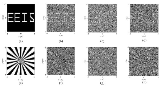
Figure 5.
Imaging results of conventional MSCI and TD-MSCI. (a,e) is the imaging target. (b,f) is the result of conventional MSCI. (c,g) is the result of TD-MSCI without coherent integration. (d,h) is the result of TD-MSCI with echo enhancement.
The scattering echoes of target 1 in conventional MSCI and TD-MSCI with the same frequency design are illustrated in Figure 6. Figure 6a,b show original echo waveform of a single transmitter and multiple transmitters under noise free condition. As shown in Figure 6c,d, the echo from conventional MSCI contains multiple frequencies, resulting in transient property in time domain, while the echo of a single transmitter in TD-MSCI should be time-harmonic, but corrupted with noise. Meanwhile, The signal levels of the two echoes differ evidently. The synthesized echoes according to the predefined radiation source are list in Figure 6e,f. As can be seen, the direct waveform synthesis without echo enhancement leads to worsened SNR than the echo of conventional MSCI in Figure 6c, while synthesis with coherent integration achieves comparable SNR condition.
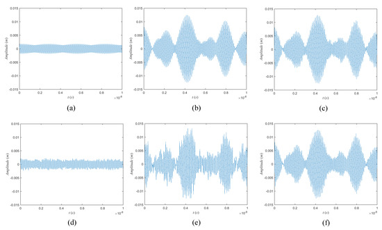
Figure 6.
Echo signals in conventional MSCI and TD-MSCI. (a) is the echo of single transmitter under noise free condition. (b) is the echo signal of multiple transmitters under noise free condition. (c) is the echo signal in conventional MSCI under fixed noise level. (d) is the echo signal of time-division single transmitter with the frequency involed in (a) under the same noise level. (e) is the directly synthesized echo without echo enhancement. (f) is the synthesized scattering echo with 16 times coherent integration.
The imaging results of conventional MSCI and TD-MSCI under the same noise level are illustrated in Figure 5, and the RIEs of the recovery results are listed in Table 2. Figure 5b,f are the recovery results of conventional MSCI. Figure 5c,g are results of TD-MSCI without echo enhancement. Figure 5d,h are results of TD-MSCI with coherent integration times of 16. As compared in Figure 5b,d,f,h, the RIE of conventional MSCI and TD-MSCI with the coherent integration time equaling the number of transmitters are close, demonstrating that MSCI based on time-division scheme and digital waveform synthesis achieves comparable imaging performance, which can be further demonstrated by 100 times Monte-Carlo numerical experiments shown in Figure 7. The RIEs of MSCI and TD-MSCI are approximately close, as illustrated in black line and yellow line in the figure.
Table 2.
Relative imaging error (RIE) of reconstruction results.
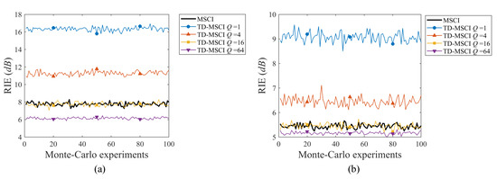
Figure 7.
RIE comparison of conventional MSCI and TD-MSCI in 100 times Monte-Carlo experiment. (a) is the result of target 1. (b) is result of target 2. Q is the coherent integration times.
4.2. Imaging of TD-MSCI with Further Optimized Parameters
To make further utilization of the available resources, the digital waveform synthesis method is select as method (1) in Section 3.3. Herein, the utilized hopping frequencies are rearranged and recombined by digital waveform synthesis, which requires increasing detection costs in simultaneously emitting MSCI, but is available in TD-MSCI by digitally rearranging the hopping frequencies and the corresponding obtained echoes.
The rearranged combinations of existing frequency hopping sequences are randomly generated and the digitally synthesized shown in Figure 3. The imaging results of the extending TSSRF are partly illustrated in Figure 8. In Figure 9, the condition number of the modified imaging matrix and actual RIE of the reconstruction result both decrease as the number of additional digital waveform synthesis increases. As can be seen, with the increasing number of digital synthesized waveforms, the imaging performance of TD-MSCI with extending TSSRF is getting better than the result of conventional MSCI. The existing design resources have not been fully utilized and exploited, that is, a huge amount in exponential term of available radiation fields remains unused in conventional MSCI, as is analyzed in Section 3. Thus better reconstruction results can be obtained based on the rearrangement of original parameters. Although the additional amount of TSSRF is relative huge, the waveform synthesis is conducted in computer rather than in actual physical environment, which means no additional detecting cost is required.
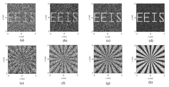
Figure 8.
Imaging results of TD-MSCI with unused frequency combinations. (a–d) are recovery results of target 1 with the amount of added TSSRF equal . (e–h) are recovery results of target 2 with the amount of added TSSRF equal .
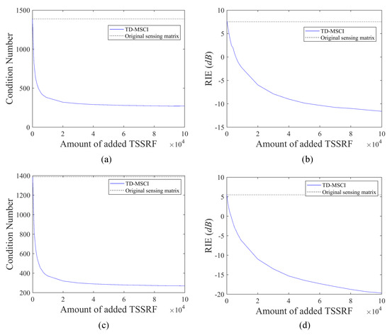
Figure 9.
Variation curve of condition number and RIE in TD-MSCI with unused TSSRF. (a,c) are the variation curves of condition number with target 1 and 2. (b,d) are the variation curves of RIE with target 1 and 2.
It should also be noted that, the proposed TD-MSCI method does not theoretically improve the imaging resolution, which is mainly determined by the given design resources such as available frequencies from the frequency band, antenna positions within the array size, and so forth. The advantage of the TD-MSCI method is that the proposed method can digitally synthesize the pre-designed TSSRF and virtually generate the undesigned radiation fields based on the given pre-designed parameters, and can make further use of the given resource with digital waveform synthesis in computer rather than in physical experiments. As can be seen in Figure 9, the condition number of the imaging matrix and RIE of the recovery results gradually converge to a limit. The phenomenon represents that, to get better imaging performance, basic detections in the time-division observation procedure should be better designed, for example, the available frequencies of each transmitter and array geometric configurations.
4.3. Imaging Experiment of TD-MSCI in Microwave Anechoic Chamber
To further verify the effectiveness of the proposed TD-MSCI method, microwave anechoic chamber imaging experiment is conducted. The imaging scenario is illustrated in Figure 10. Three trihedral reflectors are placed as the imaging target. The radar system works at X-band with the frequency band is – GHz and consists of a single transmitter and a single receiver. To implement the time-division scheme, high precision guide rail is utilized to carry the transmitting antenna. As the guide rail platform moves and stops at different positions, a virtual 1-D linear aperture is thus generated. It should be pointed out that the transmitter works only when the guide rail platform stops at a fixed position, that is, when the transmitting antenna is moving, the system does not radiate electromagnetic waves. The function of the guide rail is just to simulate the alternate transmission of the 1-D linear array, and no Doppler effects are involved here. Therefore, the imaging system can be regarded as stationary. The step interval of the transmitting antenna is 5 cm, and the transmitter stops at 7 different positions, that is, the number of effective transmitters is 7 and the virtual aperture size is 30 cm.
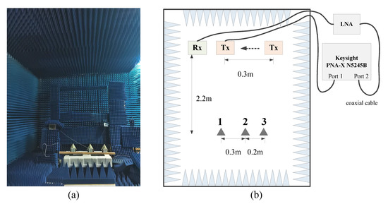
Figure 10.
Scenario of imaging experiment in microwave anechoic chamber. (a) is the real-world scenario. (b) is the geometrical scenario diagram.
A Low Noise Amplifier (LNA) is used after the receiving antenna. The Network Analyzer Keysight N5245B PNA-X is utilized as the RF modules of the transmitter and the receiver. The sweeping frequency step of the Network Analyzer is 1 MHz, thus 1000 detecting observations are acquired at each transmitting position, and the total amount of basic observations is 7000. The 2D range-azimuth imaging plane is discretized to grid-cells, with the size of each grid equals 1 cm × 1 cm.
After the procedure of digital waveform synthesis, the imaging result of the microwave anechoic chamber imaging experiment under time-division based MSCI is shown in Figure 11, where the red circles are the true locations of the reflectors recorded by an Electronic Total Station. Figure 11a shows the camera image of the targets. Figure 11b–d are the reconstructed images by MF method, Tikhonov Regularization and TV Regularization, respectively.
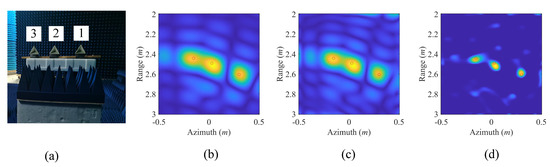
Figure 11.
Imaging results of the real-world experiemnt of TD-MSCI. (a) is the photo of the three reflectors. (b–d) are recovery results from MF, Tikhonov regularization, TV regularization method, respectively.
The range resolution and azimuth resolution of Real Aperture Radar can be calculated as
where m/s is the light speed, GHz is the frequency band, m is the vertical distance between radar and the target, m is the wavelength, and m is the virtual aperture size.
As can be seen in Figure 11, all the three reflectors can be recognized and the recovered targets are located near their real positions. Meanwhile, as shown in Figure 11b,c, the spread of the targets of MF method and Tikhonov Regularization method in the range dimension approximately equals the range resolution. The minimum azimuth distance of the three targets are m, a bit less than the azimuth range in (12), and the maximum azimuth distance of the three targets are m, a bit larger than the azimuth range. The targets 1 and 2 can both be directly distinguished with three imaging algorithms, while targets 2 and 3 are not that clearly seperated with MF method and Tikhonov Regularization method. As mentioned in Reference [11], the range resolution and azimuth resolution of MF method and Tikhonov Regularization method are both limited. But with the TV regularization method, the targets are clearly distinguished because the gradient of the imaging targets is sparse, meeting the premise of TV regularization. Therefore, the targets are well reconstructed and superior imaging result is reconstructed by the proposed TD-MSCI with TV regularization method.
Demonstrated by the above numerical imaging experiments and microwave anechoic chamber imaging experiment, the proposed TD-MSCI method possesses the potential of achieving better performing reconstruction, especially when further use of the design resources and diverse waveform synthesis are taken into consideration. Meanwhile, the time division observation can be implemented either by alternately transmitting of multiple transmitters or via single transmitter with changing positions, and the digital waveform synthesis is conducted in computer rather than in actual physical environment, namely the stochastic radiation fields are virtually generated, which significantly increases flexibility in radiation source design and decreases the detection costs compared with simultaneously transmitting based MSCI.
5. Conclusions
In this paper, a time-division based Microwave Staring Correlated Imaging (TD-MSCI) is proposed to virtually generate temporal spatial stochastic radiation fields with reduced system costs and to further utilize the available design resources of the radiation source. By alternately emitting scheme of multiple transmitters, namely time division observation, the basic scattering echoes are acquired and physically separated according to individual transmitters. Digital waveform synthesis, consisting of radiation fields synthesis and corresponding scattering echo synthesis, makes further use of the obtained detection data by rearranging the combinations of utilized parameters such as optimized frequency hopping sequences of each transmitter. Larger amount of TSSRF is obtained and better imaging matrix is achieved without extra physical observations. To make approximate approach to the real SNR situation under multi-transmission, coherent integration is adopted as the echo enhancement strategy to resolve the power coastdown and to enhance the SNR condition of the synthesized echoes. Numerical imaging experiments demonstrate the effectiveness of TD-MSCI that the proposed method achieves comparable performance with simultaneously emitting MSCI under the same source parameters, and obtains better reconstruction result with further utilization of the utilized design resources. Real-world imaging experiment is conducted with simplified system structure and achieves well-behaved imaging results. Considering that digital waveform synthesis is conducted in computer rather than in actual physical environment, the proposed TD-MSCI significantly increases the design flexibility of the radiation source and decreases the detection costs and system complexity. In future work, considering that the essential of the proposed TD-MSCI is to elaborately design the basic detection in time-division observation procedure, hence further designs of time-division observations and waveform synthesis methods will be investigated to achieve better imaging results.
Author Contributions
Conceptualization, J.Z. and D.W.; methodology, J.Z.; software, J.Z.; validation, J.Z.; formal analysis, J.Z.; investigation, J.Z., B.Y. and Z.J.; resources, J.Z.; data curation, J.Z.; writing—original draft preparation, J.Z.; writing—review and editing, J.Z.; visualization, J.Z.; supervision, Y.G. and D.W.; project administration, J.Z.; funding acquisition, Y.G. All authors have read and agreed to the published version of the manuscript.
Funding
This work was funded by National Natural Science Foundation of China under Grant No. 61771446.
Conflicts of Interest
The authors declare no conflict of interest.
Abbreviations
The following abbreviations are used in this manuscript:
| MSCI | Microwave Staring Correlated Imaging |
| RRS | Random Radiation Source |
| FH | Frequency-Hopping |
| TSSRF | Temporal-Spatial Stochastic Radiation Field |
| TD-MSCI | Time-Division based Microwave Staring Correlated Imaging |
| RIE | Relative Imaging Error |
| MF | Matched Filtering |
| TV | Total Variation |
References
- Pittman, T.B.; Shih, Y.H.; Strekalov, D.V.; Sergienko, A.V. Optical imaging by means of two-photon quantum entanglement. Phys. Rev. A 1995, 52, R3429–R3432. [Google Scholar] [CrossRef] [PubMed]
- Erkmen, B.I. Computational ghost imaging for remote sensing. J. Opt. Soc. Am. A 2012, 29, 782–789. [Google Scholar] [CrossRef] [PubMed]
- He, X.; Liu, B.; Chai, S.; Wang, D. A novel approach of high spatial-resolution microwave staring imaging. In Proceedings of the 2013 Asia-Pacific Conference on Synthetic Aperture Radar (APSAR), Tsukuba, Japan, 23–27 September 2013; pp. 75–78. [Google Scholar]
- Li, D.; Li, X.; Qin, Y.; Cheng, Y.; Wang, H. Radar coincidence imaging: An instantaneous imaging technique with stochastic signals. IEEE Trans. Geosci. Remote Sens. 2013, 52, 2261–2277. [Google Scholar]
- Li, D.; Li, X.; Cheng, Y.; Qin, Y.; Wang, H. Three dimensional radar coincidence imaging. Prog. Electromagn. Res. M 2013, 33, 223–238. [Google Scholar] [CrossRef]
- Zha, G.; Wang, H.; Yang, Z.; Cheng, Y.; Qin, Y. Angular resolution limits for coincidence imaging radar based on correlation theory. In Proceedings of the Conference 2015 IEEE International Conference on Signal Processing, Communications and Computing (ICSPCC), Ningbo, China, 19–22 September 2015; pp. 1–4. [Google Scholar]
- Zhou, X.; Wang, H.; Cheng, Y.; Qin, Y. Off-grid radar coincidence imaging based on variational sparse Bayesian learning. Math. Probl. Eng. 2016, 2016, 1–12. [Google Scholar] [CrossRef]
- Zhu, S.; Dong, X.; Zhang, M.; Lu, R.; Li, J.; Chen, X.; Zhang, A. A Super-Resolution Computational Coincidence Imaging Method Based on SIMO Radar System. IEEE Geosci. Remote Sens. Lett. 2017, 14, 2265–2269. [Google Scholar] [CrossRef]
- Zhu, S.; Zhang, A.; Xu, Z.; Dong, X. Radar coincidence imaging with random microwave source. IEEE Antennas Wirel. Propag. Lett. 2015, 14, 1239–1242. [Google Scholar] [CrossRef]
- Zhu, S.; He, Y.; Shi, H.; Zhang, A.; Xu, Z.; Dong, X. Mixed mode radar coincidence imaging with hybrid excitation radar array. IEEE Trans. Aerosp. Electron. Syst. 2018, 54, 1589–1604. [Google Scholar] [CrossRef]
- Cheng, Y.; Zhou, X.; Xu, X.; Qin, Y.; Wang, H. Radar coincidence imaging with stochastic frequency modulated array. IEEE J. Sel. Top. Signal Process. 2016, 11, 414–427. [Google Scholar] [CrossRef]
- Zhou, X.; Wang, H.; Cheng, Y.; Qin, Y.; Chen, H. Radar Coincidence Imaging for Off-Grid Target Using Frequency-Hopping Waveforms. Int. J. Antennas Propag. 2016, 2016, 1–16. [Google Scholar] [CrossRef]
- Zhou, X.; Wang, H.; Cheng, Y.; Qin, Y.; Chen, H. Waveform Analysis and Optimization for Radar Coincidence Imaging with Modeling Error. Math. Probl. Eng. 2017, 2017, 1–14. [Google Scholar] [CrossRef]
- Meng, Q.; Qian, T.; Yuan, B.; Wang, D. Random Radiation Source Optimization Method for Microwave Staring Correlated Imaging Based on Temporal-Spatial Relative Distribution Entropy. Prog. Electromagn. Res. 2018, 63, 195–206. [Google Scholar] [CrossRef]
- Yuan, B.; Guo, Y.; Chen, W.; Wang, D. A Novel Microwave Staring Correlated Radar Imaging Method Based on Bi-Static Radar System. Sensors 2019, 19, 879. [Google Scholar] [CrossRef] [PubMed]
- Skolnik, M.I. Introduction to Radar Systems; McGraw-Hill: New York, NY, USA, 1980; pp. 29–33. [Google Scholar]
- Tihonov, A.N. Solution of incorrectly formulated problems and the regularization method. Soviet Math. 1963, 4, 1035–1038. [Google Scholar]
- Hansen, P.C. Analysis of discrete ill-posed problems by means of the L-curve. SIAM Rev. 1992, 34, 561–580. [Google Scholar] [CrossRef]
- Strong, D.; Chan, T. Edge-preserving and scale-dependent properties of total variation regularization. Inverse Probl. 2003, 19, S165. [Google Scholar] [CrossRef]
- Li, C.; Yin, W.; Jiang, H.; Zhang, Y. An efficient augmented Lagrangian method with applications to total variation minimization. Comput. Optim. Appl. 2013, 56, 507–530. [Google Scholar] [CrossRef]
© 2020 by the authors. Licensee MDPI, Basel, Switzerland. This article is an open access article distributed under the terms and conditions of the Creative Commons Attribution (CC BY) license (http://creativecommons.org/licenses/by/4.0/).