1. Introduction
Cooperative communication is a significantly promising technology in providing diversity and efficient use of resources. Meanwhile, cooperative communication supported by network coding is a technique widely used for secure and effective communication without upgrading traditional network architecture on the physical layer. Network coding (NC) provides improved network capacity, diversity, efficiency, and flexibility. Joint admission control under consideration of energy efficiency, capacity, and fair usage policy plays a vital role in cooperative communication to provide uninterrupted communication.
Initially, the network coding is used for the single-mode devices, i.e., cellular devices, where devices form a wireless cluster of NC instead of all devices individually communicating to the base station [
1]. The result is increased performance in terms of data rate, robustness, delay, security, and energy consumption. The cooperative network coding then extended to the device to device (D2D) communication, which further increases the overall capacity and throughput of the network [
2,
3,
4]. The utilization of D2D and cellular network in network coding decreases the packet recovery time, and meets the performance of cellular via network coding [
5]. Satellite multicast delivery is superior to multi terrestrial cast in the number of scenarios because of the bigger footprint [
6]. Cooperative terrestrial-satellite transmission aided by satellite link increases the bandwidth, which is further strengthened by the network coding [
7,
8,
9]. The satellite is also be used as a backhaul with the advantage to offload base station [
10]. Utilizing the multiple modes under optimized network codes provides quick recovery of the lost packet and higher capacity. However, the authors did not consider the cooperative admission control based on the network code and channel condition in multiple access network devices.
Apart from multiple access control, the network code based transmission strategy has vast potential to provide good service quality under the efficient utilization of resources in future D2D content distribution [
11]. Two-level decentralized joint relay selection and resource allocation named NC-D2D proposed in [
12], assisted by network coding underlying D2D communication. Joint relay selection and resource allocation in perceptive of network coding aided by D2D explored in [
13], which consists of a two-level decentralized approach termed NC-D2D. This technique solves the relay selection and resources allocation problems alternatively to obtain stable solutions for these two problems. The Games algorithm associates the D2D with network coding, and the greedy algorithm associates the resources with the network and provides cooperative communication for resource allocation and network codes for the D2D network resource allocation with the opportunistic network coding improves the network’s performance and provides another dynamics in terms of optimization of the network [
14]. Relay based network coding has been proposed by adapting to the requirement of multi source-destination, where signals are limitedly affected by external interference and provide reliable communication [
15,
16]. The authors in [
17] define the topology and resource allocation for network coding, which increases the throughput and energy efficiency. Network aware resource allocation with random network coding for cooperative communication using a gradient algorithm in [
18] improves throughput overall. Fast resource allocation for network traffic is developed in [
19] that maximizes the utility in multicast based on the capacity and coded in the same session. The authors considered the admission control/topology and network coding separately and not optimized jointly to improve performance. Besides, multiple access, including the terrestrial-satellite network, is not considered in cooperative communication.
Designing the cooperative network code, which also considers channel condition increases the overall performance [
20]. Network codes are designed so that good channel conditions transmit the significant coded packets and increase the network’s performance. So effective joint admission control designed with network coding for multiple interfaces is essential for cooperative communication. Instantly Decodable Network Coding (IDNC) technology leads to instant decodability. It withstands with adverse channel conditions [
21], so a novel admission control method for IDNC-assisted distribution of the data algorithm is proposed but does not consider multiple interfaces. Previous literature techniques considered cooperative relay selection, resource allocation, and spatially diversity in network coding but did not account for effective admission control under joint channel conditions with random linear network codes underlying multiple interfaces. Different admission control techniques have been formulated for terrestrial-satellite networks with optimized power allocation. The purpose is to increase the throughput by using the resources efficiently [
22,
23] but did not consider the strength of network coding. The cooperative admission control (mode assignment, power allocation, and user selection) with opportunistic network coding for multiple access interfaces, i.e., cellular with D2D-satellite supported network jointly optimized adaptive to channel condition and packets available, has not been taken in literature due to its infeasible nature and complexity to best of our knowledge.
1.1. Contributions
The major contribution of this paper towards literature are as follows.
Joint formulation of admission control with network coding supported by D2D-satellite multiple interfaces leads to the complex problem due to multiple constraints and not feasible to solve as one piece. So the objective function is divided into subproblems and then solved using heuristic algorithms (ATSPSN and MANC) to maximize the capacity and lower packet completion time. In the end, the matching algorithm is used for joint optimization, which leads to convergence and less complex solution overall.
The problem formulated for joint admission control is mix integer nonlinear problem, Np hard in nature, and requires exhaustive search due to integer combinatorial nature. As its complexity increases exponentially, so using an exhaustive search method is not a feasible solution. The relaxation of the problem based on an outer approximation to linearization is proposed, ensuring convergence to a global optimum solution with less complexity. The formulated problem named Adaptive Terrestrial Power Sentient Network (ATSPSN) is then solved by NOMAD, Branch cut, and Branch bound solver.
Novel multiple access network coding framework (MANC) is proposed for stream and batch techniques supported via the D2D-satellite network. The stream technique ensures the decodability of the data immediately after receiving the packets and essential for the crucial application. Batch uses random linear network coding (RLNC) and provides less packet completion time. The theoretical lower and upper bounds are mathematically derived for lossless second stage channel, which is then extended to the second stage lossy channel for practical results.
A bi-directional matching algorithm is proposed for cooperative admission with network coding for joint optimization to provide better performance overall. The matching algorithm named as Joint Admission-Multiple Access Network Coding (JAMANC) provides the optimization in both directions, i.e., forward and backward, unlike the Gape Sharpley algorithm. The advantage is that this technique provides optimization concerning both sets, i.e., JPFL (Joint admission preference list) and MPFL (multiple access network preference list).
The satellites’ role in 5G communication with the advancement in Micro-Sat cannot be denied and part of 5G future vision. However, the link budget cost has caused slow progress in the integration of terrestrial-satellite communication. In our algorithm, the satellite is efficiently integrated to decrease overall the link budget cost.
1.2. Article Structure
The structure of the rest of the paper is as follows.
Section 2 defines the network model, which includes both the system model and the packet coding framework.
Section 3 defines the problem formulation for admission control, multiple access network coding, followed by a bi-directional matching algorithm for joint admission with network coding cooperation. First, the algorithm is formulated for a lossless channel followed by lossy channel conditions. Moreover, the complexity analysis is included in this section.
Section 4 defines the simulation and results in terms of capacity, energy efficiency, and packet completion time.
2. System Model
We considered a single cell for simplicity with the base station at the center of the cell. The same can also be used for multiple cells. Internet of things (IoT’s) and mobile users are distributed stochastically around the base station with distance
. The model is shown in the
Figure 1. The smart devices are equipped with both terrestrial and satellite antennas. D2D users act as D2D transmitters when the mode is assigned as D2D with other receivers in close proximity as per SINR calculation. The D2D receivers are statistically distributed around the transmitter using the same frequency as used by cellular links. Let
l represents all the links in our complete network model, i.e., SAT, mobile, and D2D links. The
R represents all the users selected in the network known as admission users and includes D2D
users,
cellular users, and
satellite. The channel gain
h for
links is modeled as:
where
d is distance between transmitter to receiver and
is antenna far field reference distance.
is path loss factor and
is exponential random channel.
The
and
is the optimum power allocated by our algorithm for transmission in D2D and cellular modes, respectively. The SINR calculation of terrestrial links represented as
Same terrestrial frequency resources are allocated to SAT links. The SINR of satellite users
selected in
l links are mathematically represented as
The gain of the SAT-terrestrial link includes a space environment for calculating power received by satellite. The
is optimum power allocated by terrestrial user for
links. The maximum output power of base station and satellite links denoted by
and
. An integer indicator is defined for mode selection, which is defined as.
The capacity of the network is defined mathematically as
The Coarraza–Vatalaro channel model is used, a combination of Rice and lognormal distribution, and best suits for terrestrial-LEO earth orbit communication. The pdf of Rician distribution conditioned on shadowing
s is given as:
where K is Rician factor and I
is Bessel function with zero order. Two link losses are considered, i.e., free space loss (FSL) and atmospheric loss [
24]. FSL in link distance d given as:
Network Packet Framework
The network coding framework previously considered in literature consists of the cellular links or cellular-D2D links during the broadcast of the missing packets from the base station. These techniques exploit the strength of multiple interfaces to enhance the potential of network coding. To illustrate cellular network coding (NC), consider the
Figure 2. After receiving the packets, assume due to channel noise, the p1 packet is missing from device 1. p2 packet is missing by device 2, and the p3 packet is missing for the device 03. The packets are recovered by re-transmitting the packet in cellular. In this case, 03 re-transmission is required to recover the lost packets. However, using network coding packets can be recovered in two timeslots by transmitting p1⊕p2 and p2⊕p3. The transmission has been reduced from 3 to 2.
We will exploit the strength of D2D to recover the lost data, as shown in
Figure 3. The device 1 has a p1 missing packet, so device 2 will transmit the p1⊕p3 packet via the D2D link, and similarly, the other device will transmit p1. The transmission has been reduced from 03 timeslots to 2 timeslots, increasing the network coding gain.
Consider the cooperative network coding supported by the D2D-satellite interface, which is also used in our model. Suppose the base station transmits 04 packets. p1 is missing from device 1, p2 is missing from device 2, and p3-p4 packets are missing from device 3. To recover the packets effectively, we will now use all the interfaces available to recover the packets. First, p1⊕p2 is transmitted by device 3 via the D2D link over the uplink. Simultaneously, the p3⊕p4 packet is transmitted via satellite link for devices 1 and 2. So the transmission reduced from the 4 to 1. In same timeslot, the base station sends p5, which will be received by the devices with already received all the packets in the first stage of transmission. The benefit is that p4 is now available with the devices for re-transmission in the next time slot via the D2D link, as shown in
Figure 4.
The example demonstrates that as multiple interfaces are used, then the strength of the network coding is increased to manifolds.
Let
p denotes total packets for
R admitted users.
set of packets received and
is set of device that receive packets such that
in
stage. The reception and re-transmission of the packets have been divide into 02 stages. All the packets in the
X set are broadcast via a cellular link in the first stage. In the second stage, the random linear combination of the packets is re-transmitted based on the cooperative admission network codes. The benefit for two stages is that in the first stage, only cellular links operate and result in less energy utilization because the devices need not operate in all modes, avoiding wastage of power. Second, if there is no loss in first stage, then the D2D–satellite links remain close. The benefit is lower energy and lowers link budget cost. As the cost of satellite links is expensive, so it is utilized in the second stage when deemed essential. In the first stage, all the packets
p are transmitted from the base station to R devices via a joint admission link to decrease the loss at the first stage. However, due to the scarcity of the resources and noise, few packets are lost during the first stage, with the loss factor defined as:
denotes the logarithm of real packet loss probability during the time slot
.
is the number of of lost packets and
is the number of packets that arrive. After the first stage, the set of packets lost is named as deficient
D. The set of packets received by the devices is named as acquired
A such that
. In the second stage, the packets not acquired by the devices are recovered jointly via the D2D-satellite link by utilizing the cooperative admission control with packets available in the network from the first stage. The network codes for multiple interfaces are matched with the joint admission preference list for mode selection for the best capacity and high SINR during the transmission of the packets. This approach increases the chance of the packets to receive successfully in the next time slot and provides effective utilization of the physical layers. The network code is beneficial to the satellite link during re-transmission as well, but in our case, the transmission of packets from D2D devices to the satellite is ignored. The satellite’s purpose is to relay the missing packets, so the satellite will not receive any packets by the D2D devices. This reduces the link budget cost.
3. Problem Formulation
3.1. Joint Admission Control-ATSPSN
The formulated problem consists of multiple constraints and multiple objective functions. The objective function defined as
where
and
. The utility function in (10) ensures that the user is selected only in one mode, i.e., SAT, D2D, or cellular. The utility function is either a sum-rate maximization problem or a power minimization problem. We will use the first approach as it provides more flexibility to determine the optimum power from the complete range of power available with users and sensors. The objective function, along with the constraints equation, is given as:
subject toC1: , ∨
C2: , ∨
C3: , ∨
C4: , ∨
C5:
C6:
C7: , ∨
C8: , ∨
C9: .
The objective function in (11) defines the optimum power allocation and user admission along with the appropriate mode assignment. Constraint C1 defines that the capacity of the device selected is greater than the minimum rate requirement. C2 to C6 defines the power boundaries for the algorithm. C2 and C3 ensures that power allocated to mobile user/sensors less than minimum power beyond radius (r) to avoid interference in other cell. C4 ensures that the terrestrial users’ uplink power should always be less than or equal to the devices’ maximum operating power, i.e., . The summation of all terrestrial () and satellite ( )downlinks power should be less than maximum power of base station and satellite, respectively (refer to C5 and C6) i.e., and . The power allocated cannot be zero, as ensured by C7. The C8 ensures to keep penalizing cost at low. If the capacity of link i in D2D mode is greater than or equal to SAT mode, D2D mode is selected. Terrestrial-D2D communication framework is the primary means of communication, and terrestrial-SAT is a secondary means of communication to enhance the network’s capacity and user admission. C9 ensures that users are selected in only one mode at one time.
The formulated problem is mix integer non-linear problem (MINLP). User selection is binary, while power and mode selection is an integer variable. The problem is NP-hard and relaxed to the linear problem by using outer approximation. Convex linear problem is formulated by fixing integer to upper bounds and solved using outer approximation. GAMS Branch-cut uses search space, and NOMAD uses refined directions to decrease the processing time to find a global optimum solution. By introducing a new variable
, the objective function in (11) in
iteration, mathematically represents as:
subject to C1 to C9 (11).
include set of constraints from C1 to C13,
and
. Qualification of constraints cannot be violated by fixing values of ⋎ and
is non-strictly convex for fixed ⋎. The primitive problem is given as:
By solving (13), we get
for master problem. The primitive problem provides a lower bound while the master problem gives an upper bound. The master problem consists of two steps to achieve linearization. In the first step, we project on integer space
. Mathematically, represented as:
We can Formulate (14) further as
Further, we introduce a variable as
e and projection of solution (15) in
iteration will become as
subject to
Equation (16) generate lower limits, leads to MILP. The same formulation is further solved by GAMS branch-cut and NOMAD to find an optimal solution. The Algorithm 1 give brief steps for the ATSPSN GAMS branch cut. The details about ATSPSN NOMAD and branch bound along with problem formulation are discussed in the conference version of this paper [
25].
| Algorithm 1: ATSPSN (GAMS-Branch-cut) |
1. j ← 1
2. Initializes , and constraint space
3.
4. Convergence ← Violated
5. while Convergence==Violated then for non violated space
6.
7. Upper limit
8.
9. Lower limit ← e
10 if then
11 Convergence holds
12
13
14
15 S ← Violated region
16
17 |
3.2. Multiple Access Network Coding (Lossless Second Stage)
After proposing the optimum admission control, the next part is developing multiple interfaces based on random linear network codes to decrease packet completion time by taking advantage of network coding routing. The first stage as lossy and lossless second stage is considered before developing the algorithm for a complex channel, which will be extended for lossy after developing the algorithm. The packets are lost in first stage during transmission from the base station. However, in re-transmission, there is no loss of packets. The primary aim of this approach is to evaluate the strength of our network coding without considering noise. In MANC batch, the packets re-transmitted from source/satellite and D2D are designed so that end of re-transmission, the packet completion time is minimum. First, the source determines the packets received by all the admitted devices and updates the acquired matrix A. The linear combination of the packets is sent by satellite (if all packets available) or by the source over a large field. Once packets are received, devices update their deficient D matrix until the D becomes a null set. The D2D devices with a max number of acquired A are selected for the transmission on the D2D link.
3.2.1. MANC Batch
The upper bound of the packets completion time T when transmitted by the MANC-batch is bounded mathematically by
3.2.2. MANC Stream
As compared to MANC-batch, the MANC-stream is developed so that the packets can be decoded immediately after receiving the innovative packet. The algorithm aims to achieve this goal in minimum possible packet completion time. The combination of the packets is made for the cellular communication supported by D2D-satellite links so that opportunistic network coding can be achieved from multiple interfaces. However, the exhaustive search method to look for all the possible combinations and then find the best possible combination is time-consuming and requires high computational complexity. So heuristic packet combination with linear complexity using a greedy algorithm is developed. The algorithm is divided into the following three main steps.
Scheme to create the linear combination of the packets for transmission.
Grouping the packets into sets , , and as per packets already available in the network.
Determine the appropriate mode of access to transfer the packets between satellite and D2D links.
Creating the Packet
The greedy algorithm is used for creating the packets sequentially. First, the missing packets are determined for each device. After that, the code is formed and then check with the previous codeword, if possible, combine them. The starting point will be an uncoded packet and then merged the latter to form the coded packets. If no merger can be made further, then the new uncoded packet is created and merged again, as shown in Algorithm 2.
| Algorithm 2: Creating and grouping of packets |
1. Define vector with size K for packets .
2. Initialization: .
3. for (Any device).
4. if ( desired by ).
5. and removed from .
4. Find such that then NULL then.
5. Replace with and delete ( of and should not coincide with each other).
6. is a set that consists of packets such that each element of is not similar and not equal to NULL. i.e, NULL and where .
7. is a set that consists of packets such that at least one slot is NULL, i.e.,= NULL.
8. is a set that consists of the packet that has the combination of the remaining packets. Mainly, formed by the that doesn’t contain any NULL set and at least two different packets, i.e., NULL and . |
Grouping of Packets
After creating the independent packets, they are sorted out in groups of
,
, and
based on the transmission from the source/satellite and D2D link. The packets of
are only transmitted from the source because they consist of packets not received by satellite and any D2D device during the transmission in first stage. The packets in
can be transmitted through satellite links and D2D links. However, the time required for completion for the D2D link is twice as compared to the satellite link.
is only packets that need to re-transmit from the base station. However, other then
, the
, and
offload the base station. Now in the case of the
, if they are to be transmitted by D2D link, then the same vector is divided into two vectors, which results in two transmissions while the same requires one transmission from a satellite link. The time requirement is shown in
Table 1.
Selecting Medium of Transmission
In each timeslot for transmission, two combinations of the packets are selected, such that
. One is transmitted from the base station/satellite, and the other is transmitted from the D2D link. The main aim is to achieve the packet recovery in minimum time as much possible. Now the packets in
can only be transmitted by the base station, so 1st the packets in
are transmitted. At the same time, the packets are transmitted from
and
. The
packets are transmitted from the satellite, and it targets all the devices. The
targets devices are other than its self. For instant decodability, the packets are transmitted as per the sequence of the packets. Mostly,
is transmitted first and then followed by
/
or both.The upper bound of the MANC-stream is given by
3.3. Multiple Access Network Coding (Lossy Second Stage)
The lossless second stage helps identify our proposed network coding scheme’s strength, but in reality, there is always some loss. The previous approach is not feasible as it requires a fixed set for all timeslots. The packet completion now depends on the loss in the first stage and the packets lost in the second stage. The packet completion depends upon the packet transmitted and the packets received by the target receivers, which is defined as . The admitted receivers have defined as the devices which successfully receive the innovative packets send in that timeslot. First, find the average number of the admitted receivers that receive the targeted packet successfully is calculated as . Moreover, the successful packets received given as .
MANC Batch (Second Stage Lossy)
The Algorithm 3 defines the MANC-batch for lossy communication.
| Algorithm 3: MANC Batch (Lossy second stage) |
Source packet selection criteria
1. Make a random linear combination of the packets at the higher galileos field in X.
2. The transmitter (base station/satellite) broadcast the packet innovative for all the devices.
3. For (any device in R)
4. means that packet p cannot be shown as a random linear combination of the packets in .
5. = .
6. .
7. Linear combination of the packet for .
8. x broadcasts the linear combination of the packets from the source. |
In Algorithm 3, the number of the average successful receiver during the re-transmission phase is given by the
while the receiver with
is interested in the innovative packets. To maximize the successful reception of the innovative packets, the
devices are selected in such a way to maximize the successful receivers. First, the source determines the missing packets in the devices, and second, transmit the linear combination of the packets from the source. Network coded packet from source or satellite carries information about all the missing packets from the source. So the code always maximizes the selection of maximum
devices. After selecting packets from the source, now comes the criteria to select packets from the D2D links in the local network. One device is selected as a controller based on criteria in line 6 of Algorithm 3, which selects the transmitter with the maximum number of the average receivers to have innovative packets in one transmission time slot. Moreover, the linear combination should be independent of all the packets in
. The mobile device x with the largest average successful receivers is selected as the transmitter, and if more than one, then one is selected randomly at the moment for simplicity. After transmitting from the source and via the D2D link, if the innovative data received successfully, then it is added in the matrix of the
. Now for the next transmission, again, the transmitter with the max number of
and independent from
is selected and transmits the data, which is as per our algorithm in lossless channel. The upper bound for packet completion time for the MANC-batch for lossy second stage channel is given as:
such that
MANC-Stream (Second Stage Lossy)
We will now develop the MANC stream algorithm to cater to the lossy second stage as the lossless algorithm is not feasible. According to Algorithm 2, the packets are created independent and then grouped in the sets of
,
, and
when there is no loss in second stage transmission. This approach is not suitable for the lossy channel as the sets fixed in the lossless channel, but some packets lost due to noise, and the sets’ fixed approach cannot be used effectively. Particularly in the case of
, the sets need to be changed by each reception because not all devices receive the source’s innovative packet. Second, the priority of the packets to be sent in the next timeslot in the second stage changes due to the loss of innovative packets in this stage. The main aim is to prioritize the packets, which can be received by many devices to deliver more information in lesser time. Analysis of these two reasons, it compulsory to update the Algorithm 2 for MANC- stream. The new Algorithm 4 defines the MANC-stream from the perspective of the lossy channel.
| Algorithm 4: MANC Stream (Lossy second stage) |
1. Grouping of the packets based on the into a set of the , , and using the algorithm II.
2. if (∼ isempty ).
3. first element is elected and transmitted from the source.
4. elseif (∼isempty )
5. The device with a higher number of average receivers (based on probability loss) is selected, and then packets transmitted. The transmitted packet is equal to .
6. elseif (∼isempty )
7. first element is elected and transmitted from the satellite or source based on higher average receivers.
Independent packet via D2D:
8. Consider p packet within vector in set. Any device can transmit the partial of packet p by linear network coding in the vector . The average successful receivers is given by . Find all the receiver with the corresponding packets and average successful receivers.
9. After finding all the average of the successful receivers, now send the packet from the transmitter having the maximum average successful receivers via D2D link. |
In Algorithm 4, first determines the sets of the
,
, and
by using the algorithm proposed for the lossless stage. Then two sets of a linear combination of the packets are transmitted, one from source or satellite (depending on availability of the packets) and other from local devices via D2D link. This way, more information is delivered in a one-time slot of transmission. Now, the selection of the packets from the source depends upon the average number of successful receivers in the set of
and is equal to the
. At the same time, the average maximum successful receiver from
within vector
is equal to
. Since,
is a subset of
, so
is the average successful receiver in
higher than
. Between
and
,
is sent first on the priority and after that
packets are sent from the satellite link. Now the order of transmitting the is,
at first,
as second and
as the third in the sequence. For
, the device with the maximum number of the average receivers is selected as a transmitter. Now consider the packet p from
within in vector
. Each device
transmit some part of the data available in its attained set
A. Suppose
is set of packets vector that is required by the device x. The average number of successful receivers for transmission from x is equal to
. In [
7] of Algorithm 4, it determines the maximum number of the average receivers for the
. The upper bound of the packet completion time is given as:
3.4. General Lower Bound on T
In the end, the general lower bound for transmission is developed for MANC-stream and MANC-batch when a random linear combination of the network coding is used. The comparison of our proposed algorithm is made with lower bound to find the effectiveness of our algorithm. The closer the packet completion time is with a lower bound, the better is our coding gain. The lower bound on T for cooperative network coding with multiple interface devices is given as:
3.5. Cooperative Admission Control with Multiple Access Network Coding (JAMANC Algorthim)
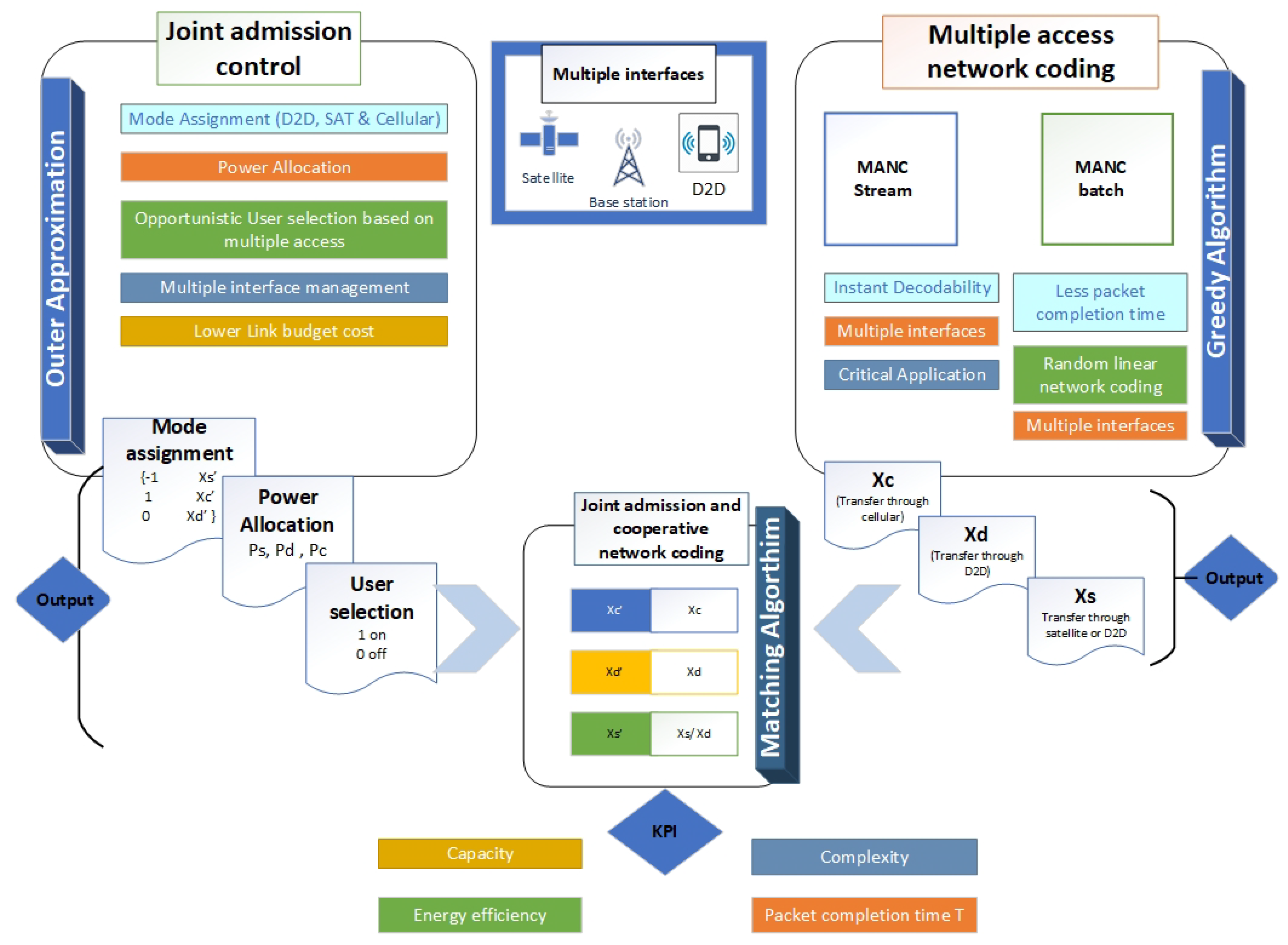
After the appropriate power allocation, user selection, and mode assignment for each device, the ATSPSN gives the preference list (mode and user selection) for all the admitted devices named JPFL. On the other hand, the MANC gives another PFL based on the network codes developed for multiple interfaces named MPFL. It categorizes the developed codes in 03 sets
,
, and
as as shown in
Figure 5.
The stable matching algorithm is developed whose purpose is to maximize the reward (capacity, packet completion time, etc.) jointly so that the benefit of both the techniques be utilized for better performance. For this purpose, a bi-directional local search matching algorithm is used [
26]. As compared to the Gale-Shapley algorithm to find an optimal solution, which is selfish matching for the first PFL, the bi-directional used to maximize keeping the in view both PFL. The egalitarian cost
, and the joint cost for stable matching with instances V is defined
is mathematically defined as:
There are several methods to search for stable egalitarian matching, which includes genetic algorithm, ant colony algorithm (ACS), approximation algorithm for finding the near-optimal solution for stable matching. As the number of stable matching (SM) tends to increase exponentially, so these techniques are not feasible in terms of the complexity. The bi-directional local search approach has better performance to attain the egalitarian matching [
27]. In this scheme, one forward from MPFL and other backward from JPFL used and found where both meet, indicating the optimal solution. For search, GALE Sharpley [
28] used while for the break joint operations [
29] is used to generate stable neighboring matching to avoid getting stuck in a local optimum. GALE Sharpley algorithm finds the man optimal stable matching; in our case, MANC optimal stable matching. At starts, the algorithm assigns no mode. At each iteration step, the algorithm selects a device from MPFL and selects the most appropriate matching from the JPFL list. If the mode in
n device from JPFL is free, it will be matched with the device from the same
n device from MPFL. If the device from JPFL is already engaged with some other device, so it rejects the matching from MPFL. The algorithm terminates when all the devices from MPFL are linked to the JPFL or show invalid matching. If MPFL and JPFL are interchanged, then the optimization is based on the JPFL instead of the MPFL. Once the pairing is done in one direction, then the break joint operation is done. Let V be a stable matching and (JPFL, MPFL) be engaged in V. The break joint problem as derived from [
29], denoted by the
, find the stable matching from V to MPFL. In the beginning, the algorithm assigns the preferred mode of the JPFL with the MPFL preference mode. The algorithm performs a sequence of matching, rejection, and acceptance based on the Gale-Shapley algorithm at each iteration. There is always 02 free mode any time execution of the algorithm, if the JPFL mode matches with MPFL mode for the corresponding device, then there is no need of other modes, and
returns a stable matching
of
l engaged pairs. The Mc Vitae and Wilson imposed conditions [
29] are used for stable matching in the break-joint JAMANC operation as follows.
Condition 1: If returns on , then the only be performed on MPFL ⊳.
Condition 2: In , only MPFL with propose, otherwise the is stopped.
At first in Algorithm 5, Gale Sharpley is used to finding the optimal matching of mode selection for JPFL and MPFL, which gives a start for the BiLS-Joint algorithm. At each iteration, within two directions, the algorithm finds a neighbor set of the current solution, which are
or
by calling
or
. The algorithm evaluates all the neighbors’ stable matchings by cost function
. The algorithm jumps to the next solution, which gives the smallest value of the
. The algorithm can also select the next solution to be a random neighbor with minimum probability to avoid getting stuck in a local optimum solution. If the next solution turns to be worse, then that direction is discarded. Similarly, if the best current solution of the direction is better than the previous, then the best is assigned to the current solution. The algorithm moves the current solution to the next and repeats all the steps. The algorithm terminates if either one of the directions has no neighbors left or two directions meet each other utilizing the MPFL mode assignment. If both forward and backward searches pause and the MPLF cost of the current matching of the forward search MPFL(
) is equal or higher then backward MPFL(
), then the results are obtained from bi-directional. This gives the best solution so far and terminates at this point.
| Algorithm 5: JAMANC Algorithm |
Input: An instance l of ATSPSN(JPFL)-MANC (MPFL) matching.
Output: A stable matching (Mode identification).
1. := GALESHAPLEY(I,MPFL);⟶ MPFL propose JPFL;
2. := GALESHAPLEY(I,JPFL); ⟶ JPFL propose MPFL;
3. if ( then
4.
5. else
6.
7. end
8. Forward := Valid;
9. Backward:= Valid;
10. while (valid) do
11. if (forward) then
12. neighborSet:= ⊖;
13. for (each device in the MPFL set) do
14. Stable Matching:= , MPFL)
15. neighborSet:=(neighborSet) ∪ (stable Matching)
16. end
17. if (small random probability p) then
18. := a random matching in neighborSet;
19. else
20. := arg ;
21. if then
22. forward := In Valid
23. if then
24.
25. end
26. end
27.
28. end
29. if (backward) then
30. neighborset:= ⊖;
31. for (each device in JPFL set) do
32. stableMatching :=
33. neighborSet:=
34. end
35. if (small random probability p) then
36. := a random matching in neighborSet;
37. else
38. := arg
39. end
40. if then
41. backward := Invalid
42. if then
43.
44. end
45. end
46.
47. end
48. if ((not forward) and (not backward)) then
49. if (MPFL( then
50. Forward := Vaild
51. Backward := Valid
52. else
53. Break;
54. end
55. end
56. end
57. while end
58. Return |
3.6. Complexity
The admission control with NC is divided into sub-problems and then jointly optimized together. The complexity depends upon the highest complexity in our sub-algorithms. In terms of time cost, the approximated big O of ATSPSN branch-cut is
, where n is the number of users. The MANC-batch and MANC-instant complexity with the second stage as lossless is
. While the complexity of the MANC-instant with second stage lossy is
. So the complexity of the MANC-instant is greater then MANC-batch as the transmission sets are calculated again after each loss of the packet. The Time Complexity of the Gale-Shapley Algorithm is
. The overall complexity of the JAMANC algorithm for stream and batch is defined (29) and (30) respectively, as:
4. Simulation Results
Monte Carlo simulation was carried out. The results are average out on 500 simulations for ATSPSN and JAMANC algorithms, where optimization is computationally extensive. The step size is taken as two devices for the ATSPSN. The step size for MANC and JAMANC algorithm is five devices and five packets. Small intervals provide better mean estimates leads to a higher confidence interval. However, 5000 iterations are used for the MANC algorithm to cater for all possible combinations of packet missing. First, the ATSPSN algorithm is compared, followed by the JAMANC algorithm, and a comparative study is carried with the MANC standalone (extended NCMI algorithm proposed in [
5]) and ATSPSN standalone algorithm [
25]. Moreover, mode analysis is done. The performance of coding is compared with the upper and lower bounds derived earlier. As per International Mobile Telecommunications 2020 (IMT-2020) guidelines [
30], the significant key performance indicators (KPIs) for the 5G network is capacity, energy efficiency, and fair usage policy. The time required to complete the packet completion is a critical factor in analyzing the network coding [
5]. Earlier packet completion time leads to better performance of the network. The standard KPIs are used to analyze the strength of our proposed algorithms.
4.1. Joint Admission Control (ATSPSN)
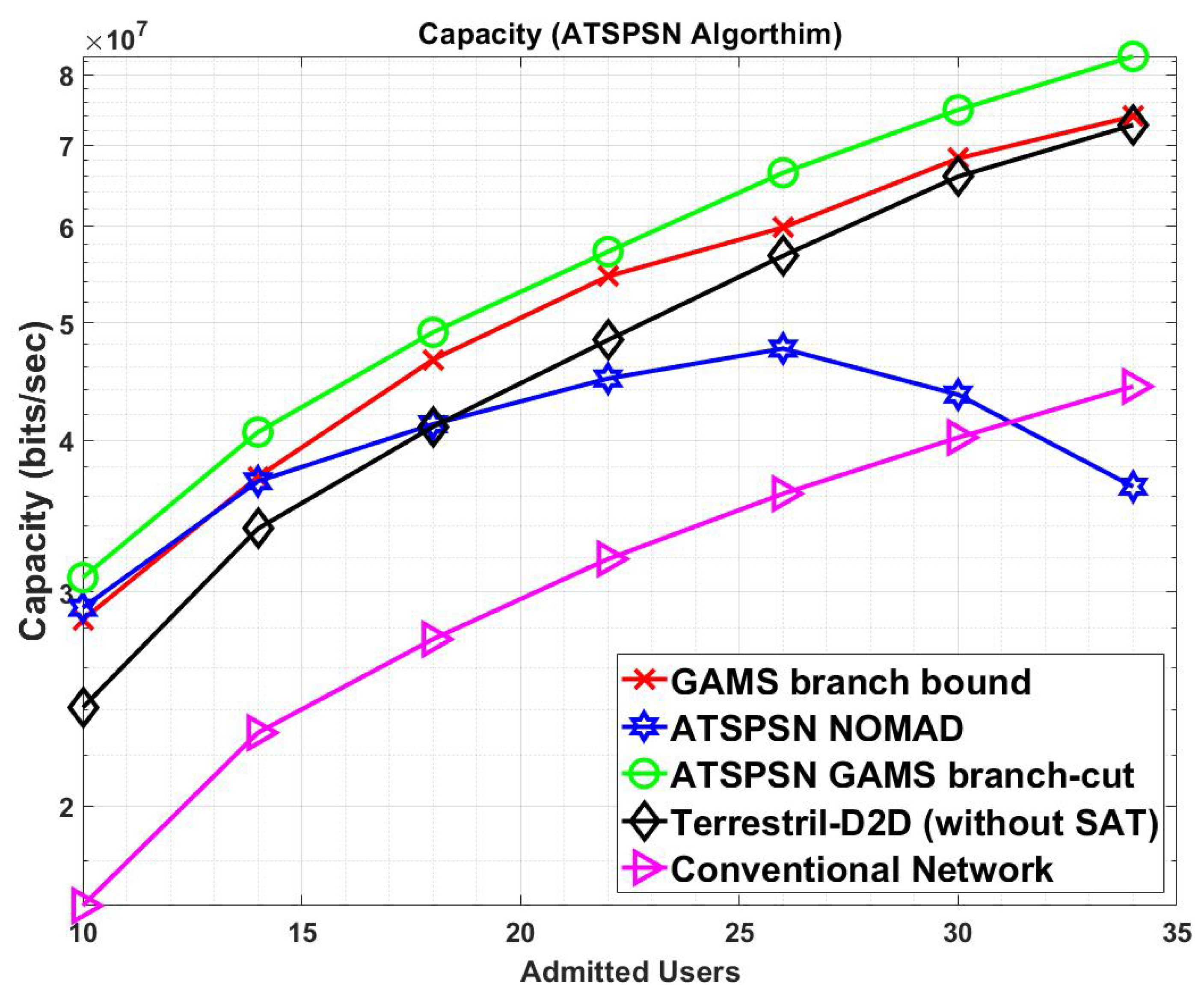
Figure 6 shows the capacity analysis of the different techniques. ATSPSN GAMS branch cut outperforms ATSPSN NOMAD, and GAMS branch bound. Moreover, when the satellite is used as a supported network, the overall capacity increases.
Figure 7 shows mode analysis in terms of the capacity. The hybrid mode, which includes joint optimization of the cellular supported by the D2D satellite network, performs better than the standalone mode. Moreover, at higher admitted users, the satellite capacity increases compared to D2D because of more interference due to an increase in operating devices. The satellite is selected in our algorithm when deemed essential, leading to less link budget costs.
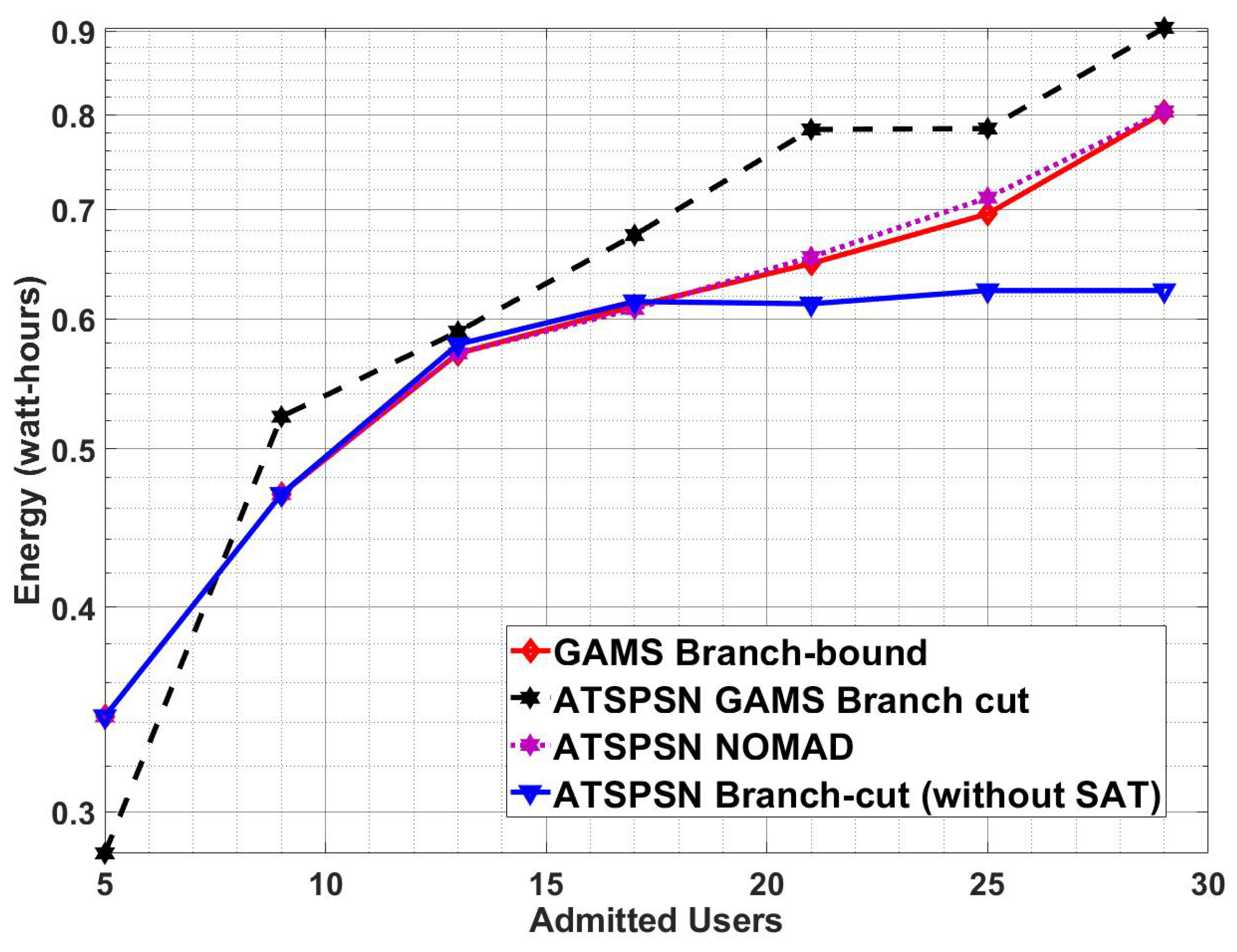
Figure 8 shows that the ATSPSN GAMS branch cut has better energy efficiency as compared to NOMAD and Branch bound due to faster convergence to the optimal solution. So our algorithm has optimum power allocation as compared to other techniques.
The detailed analysis of the ATSPSN algorithm is made in the conference version of the paper [
25], which includes admitted user’s analyses, mode analyses, and complexity. It is concluded via [
25] that the overall ATSPSN GAMS branch-cut has better performance in terms of maximization of user selection, energy efficiency, capacity, and complexity as compared to other techniques. ATSPSN GAMS branch-cut is used further to cooperative network coding (JAMANC algorithm).
4.2. Cooperative Admission Control with Network Coding (JAMANC)
Now, the JAMANC algorithm’s comparison is made with standalone techniques (ATSPSN/MANC) and standalone modes (cellular/D2D/satellite). MANC is an extended version of the NCMI (Network coding multiple interfaces) proposed in [
5] with satellite included apart from D2D-cellular communication. The quantitative performance is compared with theoretical bounds derived during problem formulation section in terms of packet completion time. ATSPSN-NoNC is defined as the algorithm with joint admission control optimization, and without network coding, i.e., the missing packets send based on channel conditions on multiple interfaces. JAMANC defines algorithms with cooperative admission control with multiple interface network coding. MANC is defined as an algorithm that consists of multiple interface codes, but the selection of interfaces does not consider optimum admission control.
First, we evaluate the strength of the network code by considering the lossless second stage.
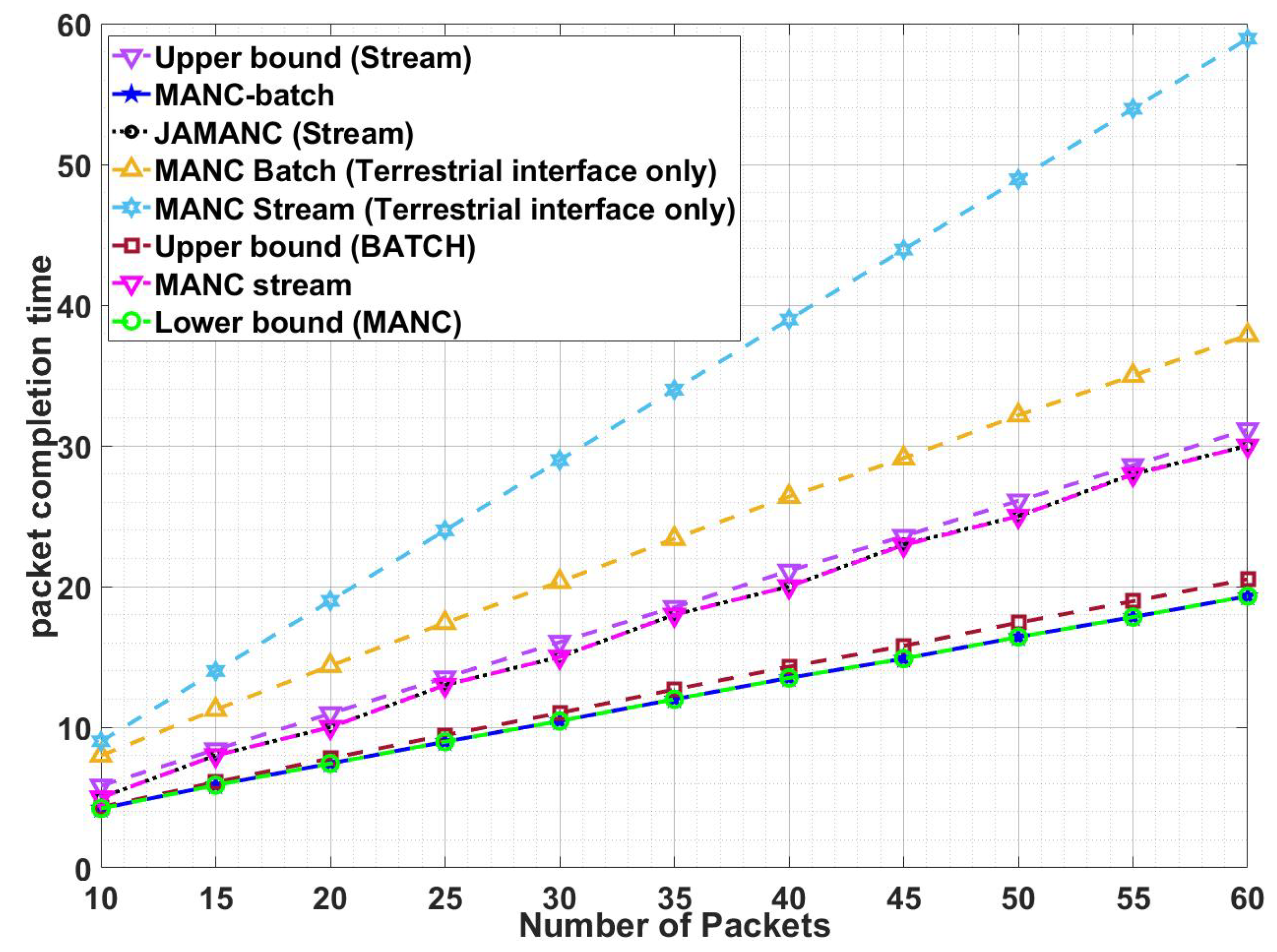
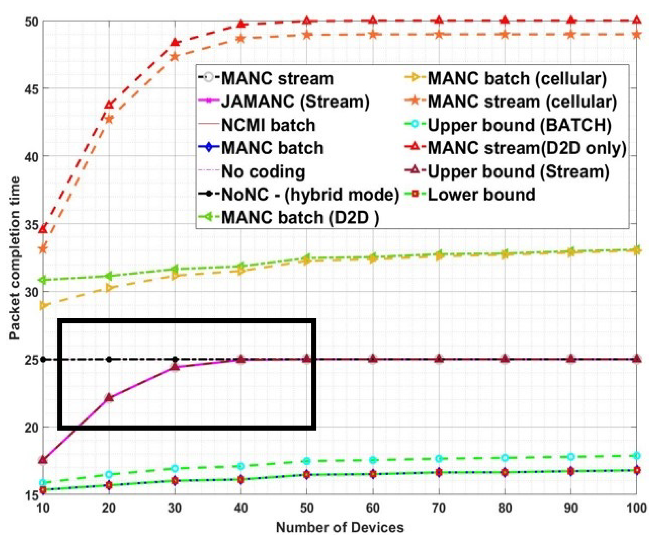
Figure 9 shows the results for the lossless second stage with requisite upper bounds. MANC batch has better performance as compared to MANC-instant. MANC batch transmits all the missing packets and the devices required to wait for all the combinations for decodability, leading to less packet completion time. On the other hand, the MANC instant transmits the data with the aim of instant decodability, so it requires more re-transmission. However, our proposed algorithm acquires the performance close to lower bounds and better as compared to NoNC. It is also to note that JAMANC has the same performance as MANC. So the joint optimization of admission control with network coding does not improve performance because all the channels are considered lossless, and using random channels for transmission does not affect the performance of the network. In terms of the number of devices
Figure 10, initially, MANC-instant performance is better than NoNC, but after a specific number of active devices, the performance becomes the same. The reason is due to each packet lost at least by one device. MANC-batch has better performance as compared to NoNC/instant and independent on the increase in the number of devices. The network code designed for multiple interfaces lowers the packet completion time, especially at higher admitted users. It is concluded that our RLNC algorithms designed for multiple interfaces lower packet completion time regardless of the increase in packets or active devices.
Figure 9 and
Figure 10 showed that the optimum NC with multiple interfaces designed based on RLNC increases the performance of the network. However, the second stage lossless, is not the realistic depiction of communication and represents the idealistic channel condition. Now moving towards the lossy second stage, the channel conditions also play a vital role.
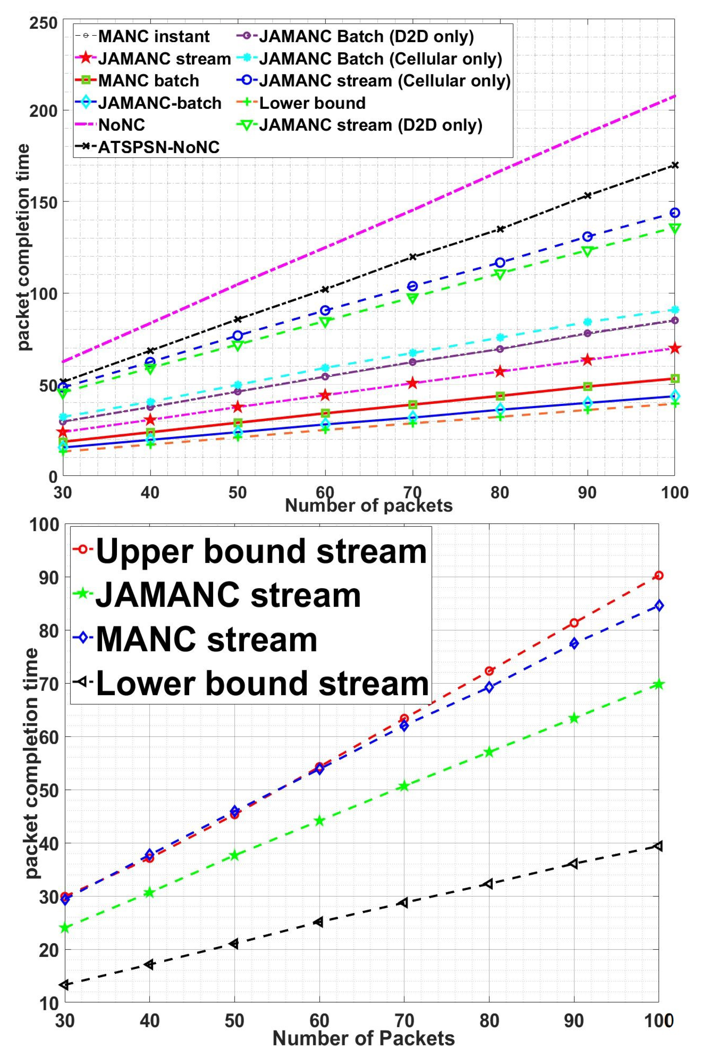
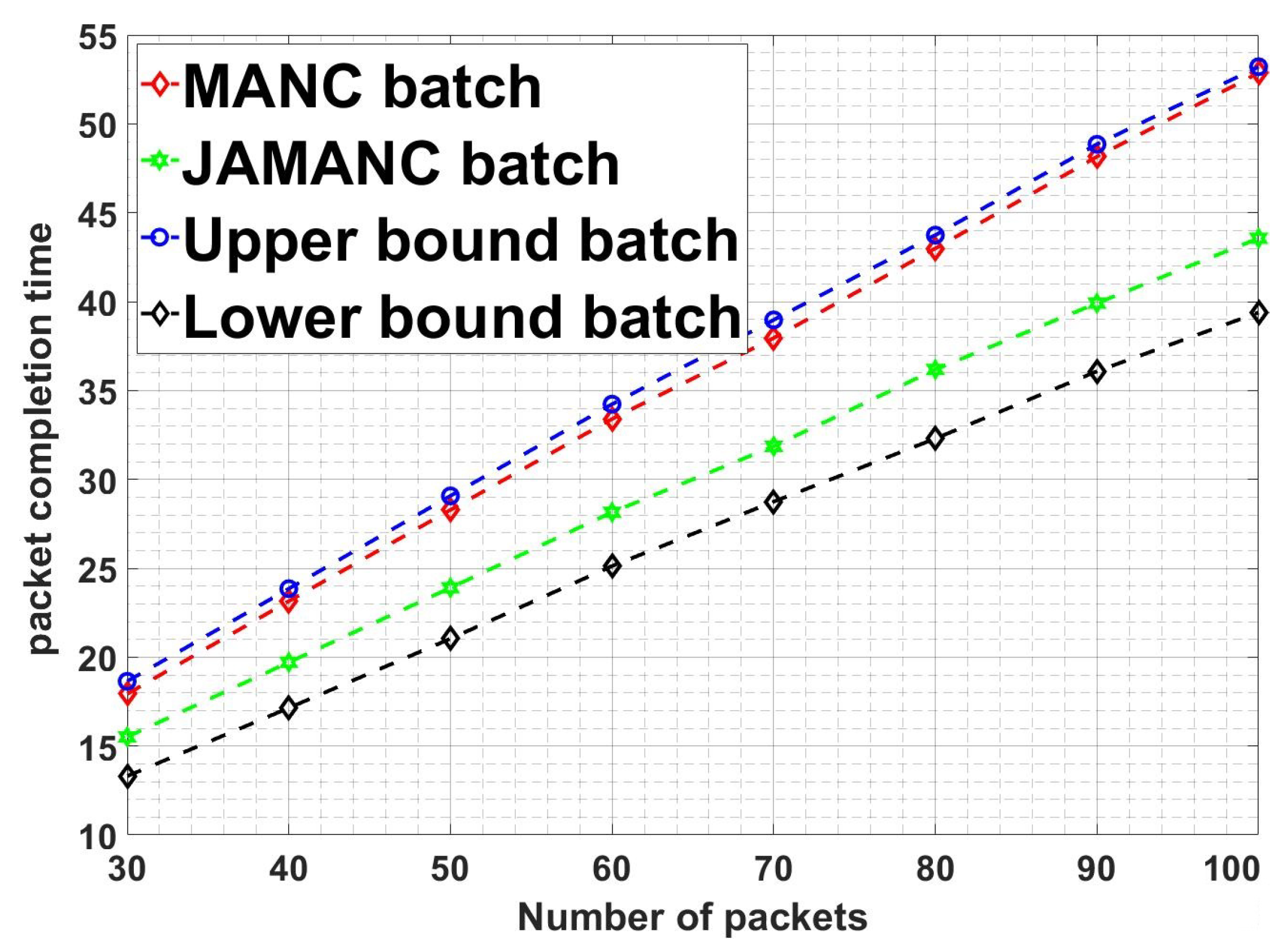
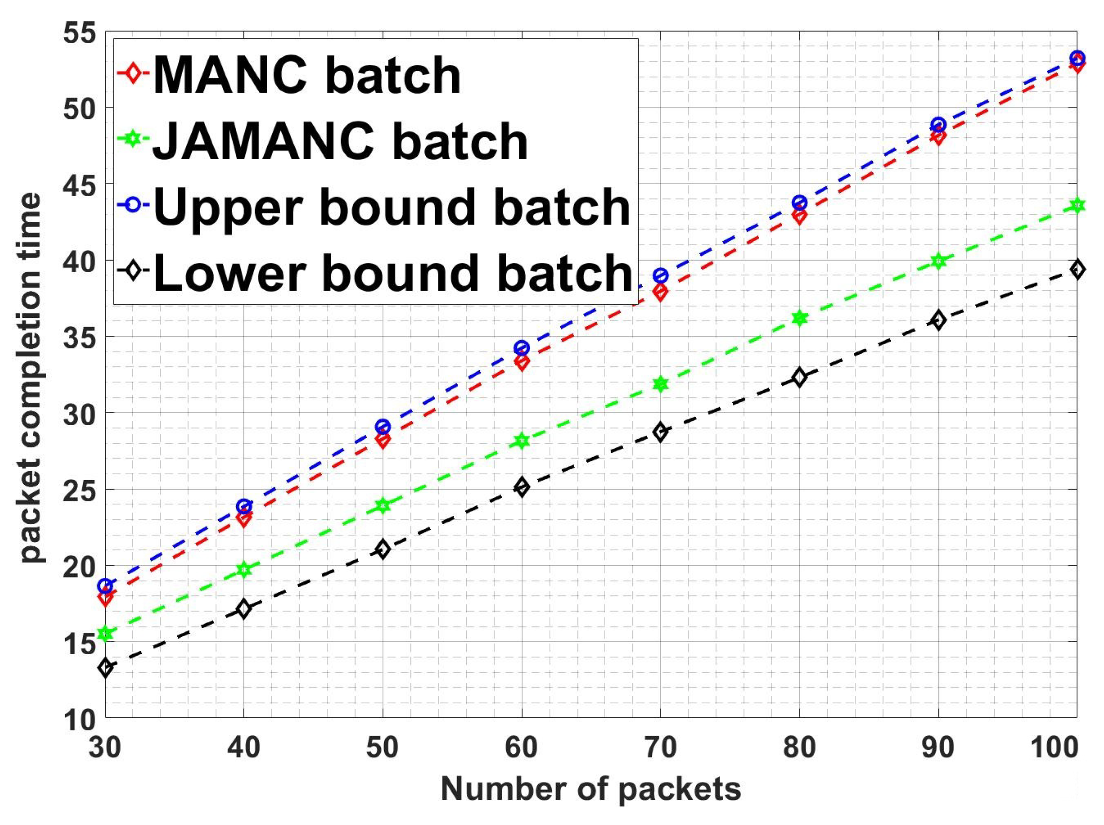
Figure 11 shows the comparison of packet completion time of different techniques and modes with the number of the packets in the second stage lossy network. JAMANC-batch, having cooperative admission with batch network coding, has better performance than JAMANC-stream and MANC standalone. It shows that if the right channel conditions send prioritized RLNC codes under optimized interfaces, it increases the network’s performance in real-time. The subfigures show that the JAMANC batch and stream have lesser packet completion time than upper bounds. JAMANC batch packet completion time is closer to lower bounds despite adverse channel conditions in second stage, which indicates that joint optimized admission control under cooperative network coding with multiple interfaces improves performance, which is the strength of this article.
Figure 12 shows a comparison of the JAMANC algorithm with other techniques and modes with the number of devices in the network. JAMANC batch has overall less packet completion time as compared to JAMANC-stream and MANC. Moreover, as the number of the devices increases, the MANC algorithm’s packet completion time increases, but in the JAMANC algorithm, the packet completion almost remains the same. It is because JAMANC caters to the channel conditions while transmitting the RLNC packets, but MANC transmits randomly without considering the channel conditions. Our algorithm’s main advantage is that the number of active devices in the network increases without compromising performance. The subfigures in
Figure 12 show that our algorithms remain below the upper bound even in adverse conditions.
We will now discuss the mode analysis of the different techniques with a number of packets and the number of devices.
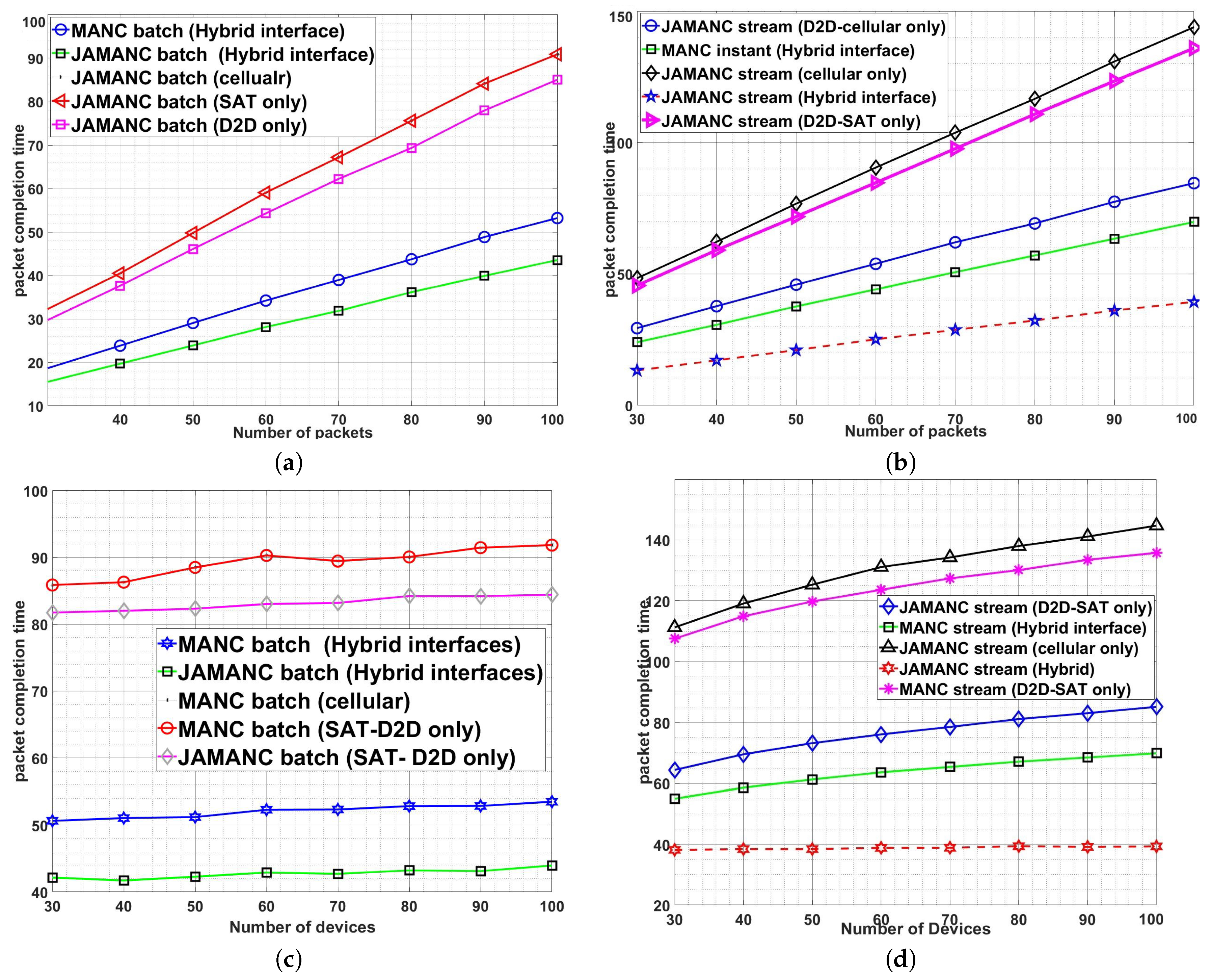
Figure 13 shows that the JAMANC hybrid has better performance and mostly independent upon the number of devices in the network in case of a batch algorithm. The simulation shows that utilizing all the three modes effectively and taking the strength of admission control with network coding increases overall performance. Similarly,
Figure 13a,b shows that with an increase in packets, JAMANC with hybrid mode, i.e., cellular supported by D2D-Satellite, has lesser packet completion time. Besides, our algorithm JAMANC selects satellite when deemed essential, reducing the link budget cost overall.
The probability of packet loss plays a vital role in performance for network coding. Now we consider the loss factor and analyze our algorithms based on packet drops.
Figure 14 shows the comparison of the packet completion time with the probability loss factor. The difference in performance between JAMANC and MANC is negligible at lesser loss factor values because of high SINR values. However, as the probability loss increases, the MANC packet completion time increases, but JAMANC packet completion time increases slowly because of effective admission control to cater to the interference (refer to zoom version of
Figure 14). The strength of cooperative admission control is shown by comparing the performance of the MANC with ATSPSN-NoNC. ATSPSN-NoNC outperforms the MANC algorithm at a higher probability loss factor because the joint channel condition plays a significant role at adverse interference. The multiple interfaces provide better performance than a single interface at a higher loss factor when JAMANC hybrid mode is selected compared to standalone modes. In short, cooperative admission control with network coding underlying multiple interfaces jointly optimized lead to better performance even at worse channel conditions or higher packet loss factor.
5. Conclusions
In this paper, we presented cooperative admission control with network coding for cellular/IoT devices supported by the D2D-satellite network. The problem formulated is divided into subproblems, and the heuristic solution is developed for each subproblem to keep the complexity of the proposed algorithm low. First, the joint admission control, which includes mode assignment, power allocation, and user selection, is formulated. The problem is MINLP, which is NP-hard. The linearization of the formulated problem is proposed, which ensure convergence. Then it is solved by GAMS branch cut, NOMAD, and branch bound solvers. ATSPSN-GAMS branch cut outperforms other techniques in terms of capacity, admitted user selection, energy efficiency, and complexity. Second, a novel network coding for multiple interfaces (MANC) has been developed for the stream and batch decodability techniques. The stream is used for instant decodability while the batch is used to lower packet completion time, where devices can wait for all linear combinations of the packets to arrive for decodability. Three sets are developed, categorizing the random linear network code for transmission from multiple interfaces, i.e., cellular, D2D, and satellite. The aim is to achieve packet completion in minimum time. For comparative study, the lower and upper bounds are derived for each technique in a lossless and lossy second stage channel. A bi-directional matching algorithm named JAMANC is introduced to find optimal mode selection and network codes utilizing the cooperative admission with MANC preference list. JAMANC is developed by coordinating the joint admission with multiple interface network coding with a supported D2D-satellite network. The simulation proves that JAMANC performs better than standalone techniques, i.e., ATSPSN and MANC, and standalone interface, i.e., cellular, D2D, and satellite. Overall, the packet completion time decreases for JAMANC-stream and JAMANC-batch with low complexity and lesser link budget cost. Our scheme proves that the cooperation between admission control based on joint channel conditions with network codes based on packets available in multiple interfaces is an effective technique to improve performance, especially at adverse channel conditions or higher packet loss.


