Article

PAPR Reduction in UFMC for 5G Cellular Systems

by
Mohammed I. Al-Rayif
1,
Hussein E. Seleem
2,
Amr M. Ragheb
3,* and
Saleh A. Alshebeili
3,4
1
Applied Electrical Engineering Department, King Saud University, Riyadh 11451, Saudi Arabia
2
Department of Electronics and Electrical Communications, Faculty of Engineering, Tanta University, Tanta 31527, Egypt
3
KACST-TIC in Radio Frequency and Photonics (RFTONICS), King Saud University, Riyadh 11421, Saudi Arabia
4
Electrical Engineering Department, King Saud University, Riyadh 11421, Saudi Arabia
*
Author to whom correspondence should be addressed.
Electronics 2020, 9(9), 1404; https://doi.org/10.3390/electronics9091404
Submission received: 8 August 2020 / Revised: 23 August 2020 / Accepted: 28 August 2020 / Published: 30 August 2020
(This article belongs to the Special Issue Wireless Communication and Networking for 5G)

Abstract

:
Universal filtered multi-carrier (UFMC) is a potential multi-carrier system for future cellular networks. UFMC provides low latency, frequency offset robustness, and reduced out-of-band (OOB) emission that results in better spectral efficiency. However, UFMC suffers from the problem of high peak-to-average power ratio (PAPR), which might impact the function of high power amplifiers causing a nonlinear distortion. We propose a comparative probabilistic PAPR reduction technique, called the decomposed selective mapping approach, to alleviate PAPR in UFMC systems. The concept of this proposal depends on decomposing the complex symbol into real and imaginary parts, and then converting each part to a number of different phase vectors prior to the inverse fast Fourier transform (IFFT) operation. The IFFT copy, which introduces the lowest PAPR, is considered for transmission. Results obtained using theoretical analysis and simulations show that the proposed approach can significantly enhance the performance of the UFMC system in terms of PAPR reduction. Besides, it maintains the OOB emission with candidate bit error rate and error vector magnitude performances.

1. Introduction

Nowadays, the wireless cellular networks are evolving rapidly to cope with the various advances in wireless technologies. In particular, Internet-of-Everything (IoE) applications and the promising fifth-generation (5G) services are the main drivers behind this revolution. To realize such type of networks, i.e., 5G and beyond, several innovative technologies at various network layers have been developed [1,2,3]. For instance, at the physical layer, new flexible and scalable modulation and multiple access technologies were proposed in order to provide high data rate systems (∼20 Gb/s) [4], superior quality of service (QoS) end-users, and low latency (∼1 ms), and energy consumption [1].
The currently used modulation scheme, in the fourth generation (4G) systems, is the orthogonal frequency division multiplexing (OFDM) [5,6,7]. OFDM can effectively combat the multi-path fading channel to provide reliable transmission and increase the system capacity. Therefore, OFDM uses a cyclic prefix (CP) and a guard interval between the OFDM symbols to avoid the inter-channel interference (ICI) and the inter-symbol interference (ISI), owing to the adjacent sub-carriers and symbols, respectively. Besides, OFDM suffers from large side lobes [8], complex design of power amplifier, owing to high peak-to-average power ratio (PAPR), synchronization errors in data aggregation; therefore, not recommended for cognitive radio and IoE networks [9]. This stimulated researchers to develop and propose robust modulation formats that can satisfy the requirements of the new wireless networks [10,11,12,13].
Recently, many alternatives to OFDM technology were proposed for the 5G air interface. These include filtered OFDM (F-OFDM) [14], filtered bank multi-carrier (FBMC) [3], universal filtered multi-carrier (UFMC) [1], and generalized frequency division multiplexing (GFDM) [15]. For example, in the FBMC modulation format, each sub-carrier is individually filtered using a filter bank to provide low out-of-band (OOB) emission, which results in lower ICI. On the other hand, FBMC shows more hardware complexity owing to the required filter length, which is impracticable in some applications, such as short-packet transmission [11]. In the UFMC system, the sub-carriers are packed and filtered as sub-bands. This reduces the filter length, making UFMC more suitable for dynamic spectrum allocation techniques in cognitive radio (CR) networks [16,17]. Furthermore, UFMC provides lower side lobe radiation, low latency, and capability of supporting frequency segmentation and multi-service applications [15]. Additionally, it is suitable for short burst communications [11,15]. UFMC uses Dolph-Chebyshev filter for each sub-band [18], where in the pass band, the valuable signals are passed without any loss, whereas in the stop band the frequency response is decaying fast to avoid OOB emission [14,19]. It is worth noticing that UFMC maintains the fundamental features of OFDM, making it relevant to multiple-input multiple-output (MIMO) applications. Additionally, in F-OFDM, the sub-bands are filtered after the CP addition for precise frequency localization. However, this method shows high hardware complexity, besides the filter tail is extending to the next OFDM symbol [14].
Nonetheless, UFMC suffers from high PAPR arising from the usage of multi-carrier transmission [11]. Several techniques for PAPR reduction were proposed in the literature [20,21]. These techniques can be classified as either signal distortion [22,23], encoding [24], or probabilistic methods [25,26]. The first method uses clipping or filtering to limit the maximum level of the signal, hence reducing the PAPR. This introduces distortions in the transmitted signal, which reflects on the system bit error rate (BER) performance [21]. Additionally, the encoding schemes cause low data rate efficiency [27,28]. On the other side, the probabilistic methods, such as the selected mapping (SLM) [29,30,31] and partial transmit sequence (PTS) [28,32], introduce random phase shifts on the transmitted symbols as a pre-coding step without causing significant distortions. However, this comes at a cost of a low spectral efficiency (SE), owing to the side information transmitted to the receiver to recover the original symbol vector. In this regard, many proposals were demonstrated in the literature to enhance the SE by obtaining the side information blindly at the receiver side [33].
Several works have been proposed to cope with the challenge of PAPR in the presence of UFMC system. In [34], the PTS technique is applied to the UFMC waveform, where phase factors are multiplied by the partitioned data sub-blocks. However, this method shows a higher computational complexity, owing to the high number of inverse fast Fourier transform (IFFT) operations. In [35], a low complex PTS scheme is developed for UFMC systems. In [21], a hybrid scheme that consists of a combination of pre-coding and non-linear companding techniques has been proposed and two different PAPR reduction methods are compared in terms of PAPR and BER performances. Additionally, an efficient piecewise non-linear companding transform for PAPR reduction in UFMC systems has been proposed in [36], where the proposed companding method shows an efficient trade-off between PAPR reduction and other system performance metrics such as BER and OOB radiation. In [20,37], the authors proposed a low complexity SLM-based PAPR reduction approach for UFMC systems, in which it utilizes the linearity property of the UFMC modulator. However, to the best of our knowledge, non acceptable solution has been yet provided to reduce the high PAPR while protecting the signal from the OOB radiation effect and keeping the BER performance to its minimum levels.
In this paper, we propose a new method that is based on the SLM scheme, named Dcomp-SLM scheme standing for decomposed SLM, where both the high PAPR and OOB radiation perform satisfactorily. The Dcomp-SLM concept has been initially presented in [38] in the context of OFDM transmission. In this paper, we expand the work of [38] and address the PAPR reduction in UFMC systems. Thereafter, we compare the performances of both OFDM and UFMC systems in terms of PAPR, BER, error vector magnitude (EVM), and power spectral density (PSD) in the presence of Rayleigh fading and additive white Gaussian noise (AWGN) channels. Moreover, the proposed Dcomp-SLM scheme is compared with the reduced-complexity efficient SLM (E-SLM) and the modified SLM (P-SLM) approaches in [20,37] under the same simulation parameters. The main contributions of this paper are as follows:
  • We propose a Dcomp-SLM algorithm to mitigate PAPR in UFMC systems. This method not only maintains the PSD of the UFMC system but also reduces the complementary commutative-distribution function (CCDF) to remarkable levels compared to recent proposed solutions [20,37].
  • We assess the performance of the proposed Dcomp-SLM using communication metrics such as BER and EVM, in the presence of Rayleigh fading and AWGN channels.
  • We maintain the same order of computational complexity as conventional SLM methods; however, with superior PAPR mitigation performance.
The rest of the paper is organized as the following: Section 2 describes the UFMC system model, while Section 3 presents the proposed PAPR reduction method. The numerical results and discussion is introduced in Section 4, while conclusions are presented in Section 5.
The notations used in the paper are summarized, as follows: upper/lower-case boldface letters denote matrices/column vectors, whereas lower-case letters denote scalar; A T and A H denote transpose and conjugate transpose, respectively; | A | is the determinant. E [ . ] denotes an expectation operator; C M × N denotes a space of M × N matrices with complex entries.

2. The UFMC System Model

The UFMC modulation format is a type of multi-carrier system, which converts high data rate signal into parallel lower rate streams. In contrast to OFDM, the UFMC system divides the entire band of N s c sub-carriers into B sub-bands each contains N b sub-carriers, where b = 1 , 2 , . . . , B . Then, the data in each sub-band is processed by N-point IFFT and sub-band finite impulse response (FIR) filter, respectively. Next, the filtered signals in all sub-bands are added together and the time domain UFMC signal is generated. Figure 1 deonstrates the typical UFMC transceiver block diagram.

2.1. UFMC Transmitter

As can be seen in Figure 1, the UFMC transmitter works as follows. First, the information bits are mapped into M-ary quadrature amplitude modulation (M-QAM) symbols (e.g., M = 16 ). Subsequently, N s c symbols are grouped to form the entries of vector S ; that is, S = [ S ( 0 ) , S ( 1 ) , . . . , S ( N s c 1 ) ] T . The symbols of S are divided into B sub-sequences, each is of length N b = N s c / B , to form B parallel new sub-sequences S b ( b = 1 , 2 , , B ), defined as:
S ¯ b ( k ) = 0 if 0 k N + ( b 1 ) N s c B 1 S ( k ) , N + ( b 1 ) N s c B k N + b N s c B 1 0 , N + b N s c B k N 1
where N = ( N N s c ) / 2 . Note that the length of S b is N ( N s c ) . The sub-sequence S b undergoes N-point IFFT to obtain the discrete-time signal s b ( n ) ; that is,
s b ( n ) = 1 N k = 0 N 1 S b ( k ) e j 2 π k n N , 0 n N 1 ; 1 b B
It is obvious from Equations (1) and (2) that each symbol is allocated to one sub-carrier, and that the N s c symbols are divided equally and carried over B parallel sub-bands. In Equation (2), n and b correspond to the sub-carrier and sub-band indices, respectively.
The N-point IFFT output of each sub-band is filtered using digital filter of length L f to form a UFMC signal of length ( N + L f 1 ), which can be written as:
x ( k ) = b = 1 B l = 0 L f 1 s b ( k l ) f b ( l ) , k = 0 , 1 , , N + L f 1
where f b ( l ) are FIR filter coefficients, for l = 0 , 1 , , L f 1 . Because of the CP and convolution operations carried out in the time domain, the length of sub-band signals increases from N to N + L f + L c p 1 where L c p is the cyclic prefix length. Hence, the transmitted UFMC signal x C ( N + L c p + L f 1 ) × 1 can be expressed in matrix form as:
x = b = 1 B F b D ¯ S b
where F b C ( N + L c p + L f 1 ) × ( N + L c p ) is a Toeplitz matrix composed of the filter impulse response of the b t h sub-band, with the coefficients of each sub-band filer are chosen to be normalized, such that l = 0 L f 1 | f b ( l ) | 2 = 1 . D ¯ = [ D c p : D ] H C ( N + L c p ) × N , where D C N × N denotes the FFT matrix whose element is given by 1 N e x p j 2 π k n N and ( k , n = 0 , , N 1 ) and D c p consists of the last L c p columns of D (where L c p is denoting the CP length). S b C N × 1 is the symbol vector transmitted on the b t h sub-band.
Different kinds of digital FIR filters can be used. These include Hamming, Hanning, Chebyshev, and Blackman filters. Digital FIR filers are used to solve the OOB emission problem and improve the PSD efficiency. In this paper, the optimal Dolph Chebyshev filter was considered for sub-band filtering [18,39]. It has special characteristics, as it contains equi-ripple side lobe level (SLL) with narrow main lobe width for given ripple ratio and filter length L f [40]. The characteristic of Chebyshev window is expressed, as follows [40].
w ( l ) = ( 1 ) l cos L f cos 1 β cos ( π l / L f ) cosh L f cosh 1 ( β ) × R ( l ) , 0 l L f 1
where L f is the Chebyshev window length and β is the side lobe attenuation, and R ( l ) is the rectangular sequence. Hence, the Dolph–Chebyshev filter will be expressed as f ( l ) = f d ( l ) w ( l ) where f d ( l ) is the ideal linear phase filter.

2.2. UFMC Receiver

When considering perfect frequency synchronization, the signal y C N + L f 1 × 1 at the receiver side after CP removal and zero forcing channel equalization will be given as:
y = D ¯ ¯ H H 1 H x + D ¯ ¯ H n
where H C ( N + L c p + L f 1 ) × ( N + L c p + L f 1 ) is the equivalent channel convolution matrix of h ( t ) that follows the Rayleigh fading distribution, and n C ( N + L c p + L f 1 ) × 1 is a zero mean AWGN with variance σ 2 at the receiver. The demodulation matrix D ¯ ¯ is given as D ¯ ¯ = [ 0 : D ] C N + L f 1 × ( N + L c p + L f 1 ) , where 0 C N + L f 1 × L c p denotes the zero matrix CP removal and D C ( N + L f 1 ) × ( N + L f 1 ) denotes the FFT matrix.
Subsequently, the output signal y is zero padded with N L f + 1 zeros to avoid ISI. Afterwards, 2 N -point FFT is used to obtain the received sequence, where only the even index samples of the total 2 N complex samples are taken and the odd indices are discarded. Finally, the output passes through frequency domain equalization to detect the transmitted symbols S ^ and the symbol de-mapping demodulates the output signal from the equalized signal to restore the estimated bit sequence.

3. The Proposed Dcomposed SLM PAPR Reduction Technique

Assume a typical UFMC system, as in Figure 2 with N s c sub-carriers. The UFMC system accepts a number of data bits, which are mapped into the baseband symbols using M-QAM/M-PSK mapper.
Then, these complex symbols are packed to B parallel N-point sequences, S b . The S b sequences are Dcomposed into their real S b ( k ) and imaginary S b ( k ) components for all k = 0 , 1 , , N 1 . Subsequently, each component is multiplied with the corresponding element of the random candidate phase P u ( k ) u 0 , 1 , , U 1 , where U is the overall generated phase blocks and P u ( k ) { 1 , 1 } . The element-wise multiplication operation can be formulated in matrix form as S r u = { S b } P u and S i u = { S b } P u for the real and imaginary parts, respectively. The resultant signals S r u and S i u are the rotated vectors. An UFMC system is applied for each modified components, S r u and S i u in addition to the the original symbols S b , such as: x r u = UFMC [ S r u ] and x i u = UFMC [ S i u ] , x o r g = UFMC [ S b ] , respectively, where the UFMC { } means the operations applied, as given in Equation (4).
Subsequently, the candidate signal x v is transmitted, where v denotes the vector of minimum PAPR. The definition of the transmitted signal x v PAPR can be expressed as:
PAPR = 10 log 10 P P e a k P a v g = 10 log 10 max n x n v 2 E x n v 2 .
where P p e a k is the maximum instantaneous power and P a v g is the average power of x v . The performance of the Dcomp-SLM reduction technique is analyzed by calculating the CCDF of the lowest PAPR obtained for an UFMC symbol of Equation (7). Subsequently, the candidate UFMC symbol with the minimum PAPR is considered for transmission, such as:
x u = x u arg min 0 u U 1 PAPR o r g , PAPR r u , PAPR i u .
Theoretically, the CCDF of PAPR u is defined as the probability that the minimum PAPR u exceeds a given threshold PAPR 0 , when applying U trails for both real and imaginary parts separately. Therefore, the CCDF will be approximated to:
Pr ( PAPR u > PAPR 0 ) 1 1 e PAPR 0 α N U 2 ,
where N is the number of sub-carriers per UFMC block, and α is introduced, so that this approximation matches practical results [41]. It is worth noting that at the receiver side the original phases can be recovered by implementing any appropriate selective mapping technique for a phase vector recovery. For convenience, in our work, the methods of [25,26] are used, which provide solutions for original data phase recovery without explicit side information Finally, the modified energy per transmitted symbol of our proposed approach can be expressed as: E s = E s [ 1 + ( C 1 ) / ( U + 1 ) ] , where E s is the original energy per symbol and C is the extended factor.
For all the probabilistic techniques (SLM and PTS), the main source of computational complexity is originally owing to IFFT operations. Therefore, in the proposed algorithm, we consider the fundamental complexity of the IFFT as a reference. In other words, the computations complexity of the system is ( U + 1 ) N 2 log 2 N and ( U + 1 ) N log 2 N for complex multiplications and additions, respectively, where the extra operation added (U+1) is for the original operation of the IFFT to which no PAPR reduction process is applied. Accordingly, the proposed Dcomp-SLM is implemented at the same order of magnitude of computational complexity as conventional SLM techniques.

4. Numerical Results and Discussions

In our numerical simulations, the problem of high PAPR of the UFMC waveform is addressed. It is worth noting that all of the simulations are developed by M A T L A B simulation tool. The results of the proposed Dcomp-SLM technique is discussed when the SLM reduction method is integrated to the UFMC transmitter. By modifying the phases of each component of the base-band symbols, the performances of the proposed Dcomp-SLM technique is analyzed. Subsequently, the curves of CCDF-PAPR, BER/EVM, and PSD are obtained and compared to the theoretical performances. These results are obtained when implementing the proposed method at different parameters, as shown in Table 1, assuming a solid state power amplifier (SSPA) (the Rapp’s model of [42]) as a nonlinear HPA at the UFMC transmitter end, i.e., to test the impact of the non-linear power amplifier on the performance of the proposed algorithm, and Rayleigh fading and AWGN channels.

4.1. The CCDF-PAPR Performance

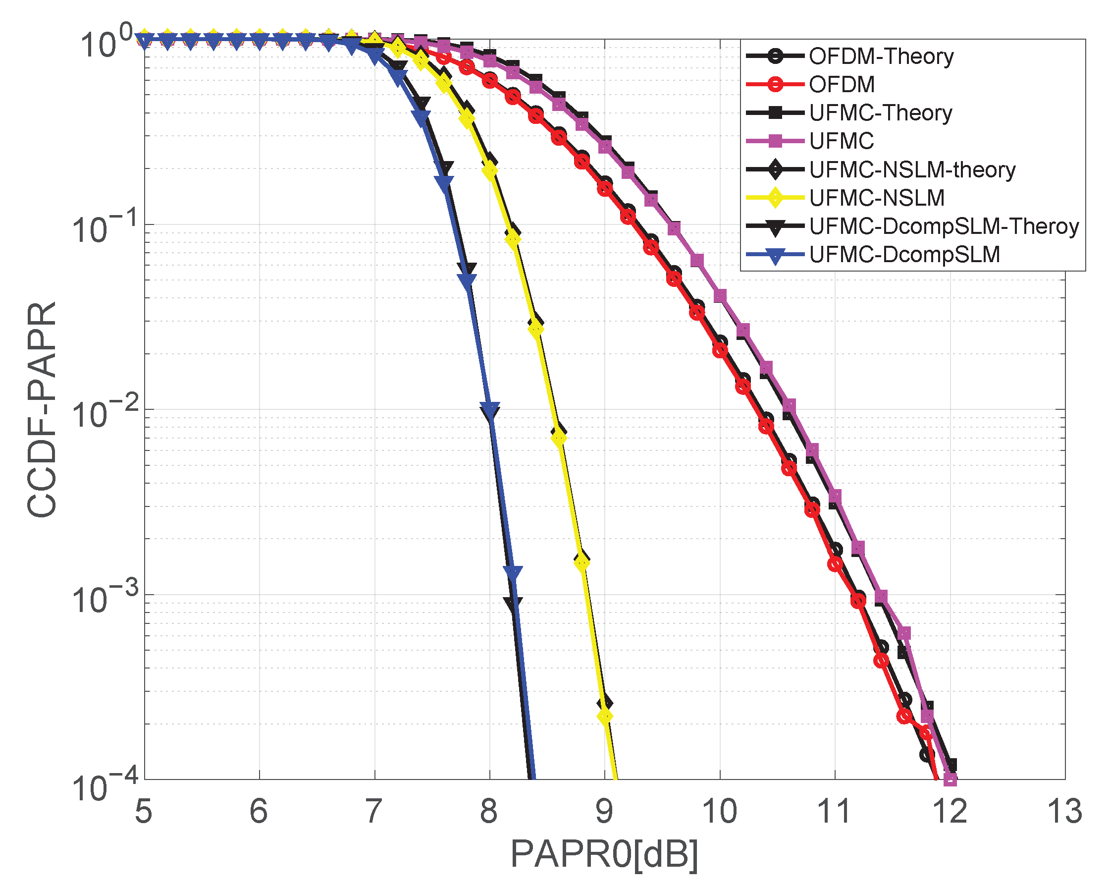
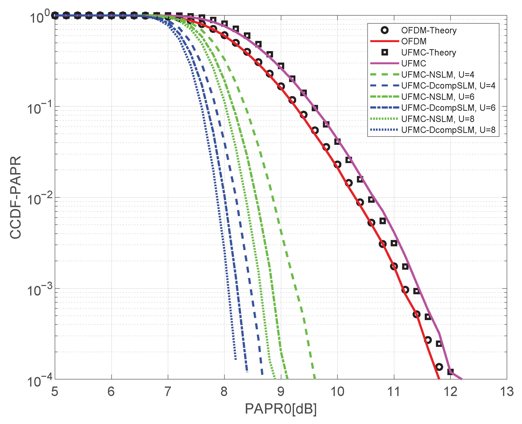
This section investigates the CCDF-PAPR performance when testing the UFMC system by applying two methods. The first method is the normal SLM (NSLM), and the second is the proposed Dcomp-SLM scheme, as shown in Figure 3 and Figure 4. Figure 3 shows two important observations; the first is that the UFMC technique suffers from a high PAPR even more than the OFDM technique. Second, the proposed technique is capable of alleviating this difficulty, and producing results that are better than the conventional SLM, besides the simulated results of Dcomp-SLM match the theoretical results given by Equation (10). Furthermore, in Figure 4, the UFMC and OFDM performances were shown at different numbers of candidate phase vectors U, which is U = 4 , 6 , and 8 vectors. As can be observed clearly, while the NSLM can improve the original CCDF-PAPR performances for all Us values, the proposed Dcomp-SLM shows further PAPR reductions for all cases. For example, Dcomp-SLM gains about 1 dB over the NSLM at Pr ( PAPR > PAPR 0 ) = 10 4 , N = 512 sub-carriers and input-back-off (IBO) = 7 dB and U = 6 phase vectors.
Furthermore, the proposed Dcomp-SLM technique is better than the E-SLM and P-SLM approaches that were proposed in [20,37], respectively, by approximately 0.5 dB at 10 4 CCDF under the same simulation parameters.

4.2. BER and EVM Performance

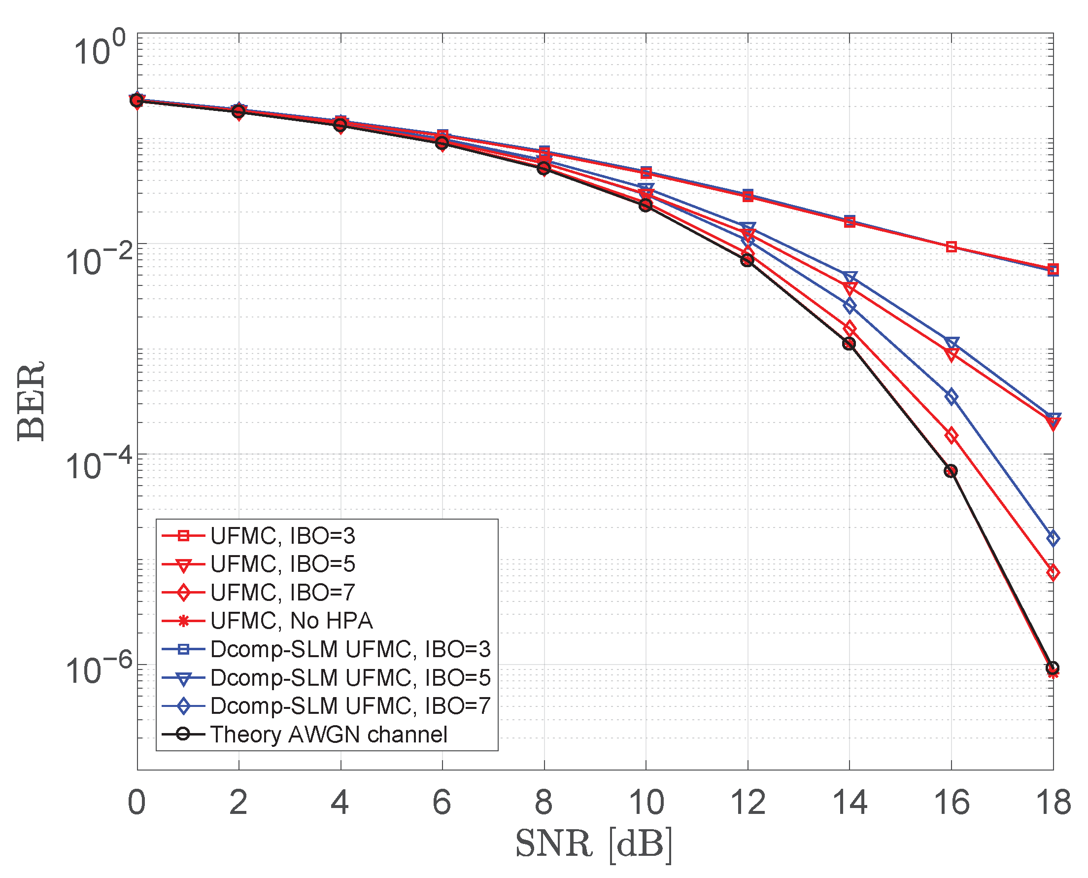
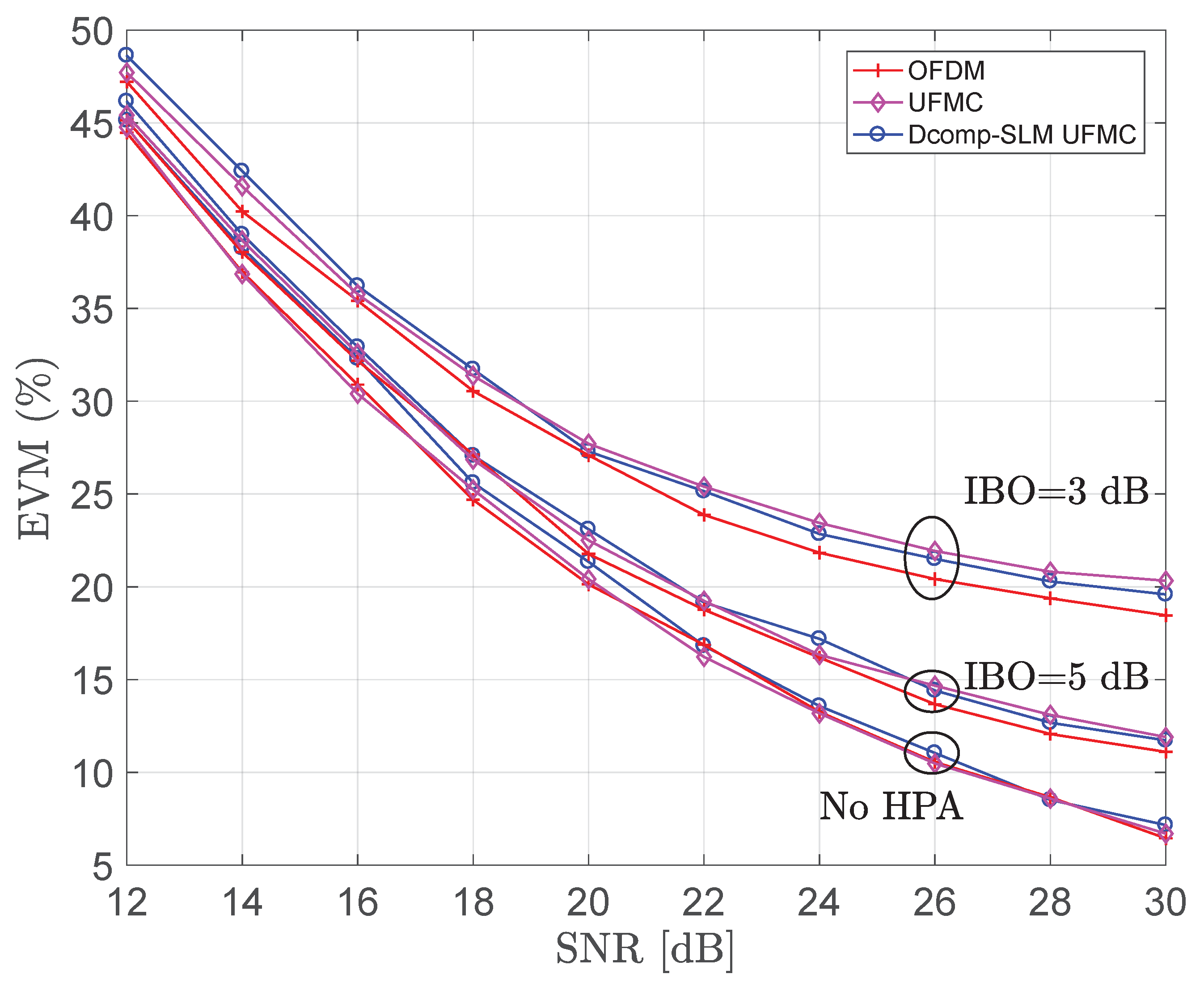
In this section, we investigate the BER and EVM performances at the presence of both AWGN and Rayleigh fading channels. We apply the proposed Dcomp-SLM to the UFMC system and compare the performance with that of original UFMC and OFDM signals at various IBO values, i.e., IBO = 3, 5, and 7 dB, and for U equals 6 phase vectors, as depicted in Figure 5, Figure 6, Figure 7 and Figure 8.
Figure 5 illustrates the AWGN BER performances, while Figure 6 illustrates the AWGN-based EVM performances. The latter shows that our proposed Dcomp-SLM outperforms the original UFMC (without a PAPR reduction) at the low level of IBO, e.g., at IBO = 3 dB, while the proposed performance is identical with OFDM at IBO = 7 dB. Moreover, in Figure 5, while the level of IBO is increased, the overall characteristics are improved and perform close to the theoretical curve, even though the proposed method performs worse than the UFMC only at low SNR. In addition, the impact of multi-path fading channel is illustrated in Figure 7 and Figure 8. In these figures, the proposed technique demonstrates performances which, almost, are identical to the theoretical ones, especially when increasing the level of the non-linear PA (i.e., IBO), for both the BER and EVM metrics, in the presence of fading channel.

4.3. The PSD Performance

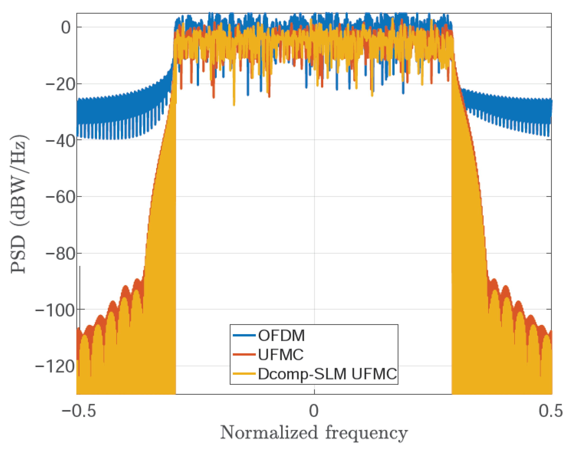
In this section, the power spectral density performance of the proposed method with respect to the OOB emission has been studied. It can be seen that the Dcomp-SLM method has better PSD as compared with OFDM and UFMC systems, as shown in Figure 9. Hence, besides the remarkable CCDF-PAPR improvement, the proposed Dcomp-SLM provides an enhancement in the PSD as well, while the system performance is maintained. It is possible to recognize that, while the normal UFMC reduces the side peak of the OFDM to about −90 dBW/Hz, the proposed Dcomp-SLM contributes further reduction; that is ∼5 dBW/Hz, over the conventional UFMC.

4.4. Discussions

So far in the previous subsections, we show the improvements that have been added to the UFMC system, owing to the proposed Dcomp-SLM. This includes a reduction in PAPR while maintaining the BER and OOB emission performance. This enhances the potential utilization of UFMC systems in 5G communication networks. In addition, in this section, comparisons between the proposed Dcomp-SLM, E-SLM [20], P-SLM [37], PTS [34], and LC-PTS [35] approaches are conducted based on the BER, CCDF-PAPR, OOB, and computational complexity. The various parameters that are used in the simulations are summarized in Table 2. In this table and for fair comparisons, we consider those methods that can be classified within the same family of the probabilistic techniques. Consequently, the table clearly shows that the Dcomp-SLM approach outperforms other compared approaches in terms of PAPR reduction ability, BER, and PSD. For instance, at 10 3 CCDF-PAPR, the Dcomp-SLM based UFMC system can provide PAPR of 8.2 dB, whereas the P-SLM, E-SLM, and LC-PTS approaches provide PAPR of approximately 8.4 dB, 8.6 dB, and 8.8 dB, respectively. Besides, the proposed Dcomp-SLM can achieve this PAPR reduction with a remarkable lower complexity. Precisely, the Dcomp-SLM is implemented with U = 6 phase vectors, while the P-SLM and E-SLM methods were implemented with U = 16 phase vectors. Additionally, the LC-PTS technique introduces an extra sub-division parameter K for the V IFFT copies which is equivalent to V K phase vectors, hence more complexity. On the other side, though the PTS approach in [34] provides 7 dB PAPR reduction, owing to the transmitted frame of length N = 256 subcarriers and phase vectors of U = 16, it requires 18.3 dB SNR to reach 10 3 BER which is 4.3 dB higher than our proposed approach (i.e., E b / N 0 = 14 dB).
Finally, as mentioned before, in this paper we consider the main source of the computational complexity, which is owing to the operation of the IFFT system. Accordingly, the fundamental complexity of the IDFT was considered as a reference for comparisons between the different techniques. Based on that, the proposed Dcomp-SLM, P-SLM, and E-SLM schemes were implemented, almost, at the same computational complexity as conventional SLM techniques. While the method of LC-PTS introduced an extra complexity over the others because of the sub-division factor K. However, the PTS approach of [34] shows the lowest complexity when comparing to all other schemes, which operates the IFFT system at complexity of ( B + U + 1 ) N 2 log 2 N multiplications and ( B + U + 1 ) N log 2 N additions.

5. Conclusions

In this paper, to meet the needs of the 5G communications and beyond, a comparative probabilistic technique, called Dcomp-SLM, was proposed in order to mitigate the PAPR distortion in UFMC systems. The proposed method is able to cope with the drawback of high PAPR and OOB radiation, simultaneously, which occur when transmitting a multi-carrier signals. The Dcomp-SLM achieves about 1 dB over the conventional SLM to decrease the PAPR of the transmitted UFMC waveform. Additionally, it shows about 5 dBW/Hz enhancement in the PSD performance over the conventional UFMC system. Moreover, the proposed method shows a negligible deterioration in the BER and EVM with respect to the theoretical results in the presence of both AWGN and Rayleigh fading channels. Hence, these results prove that the UFMC system is feasible and it could be implemented in the case of the multiband transmission that is used by 5G technologies. Therefore, UFMC can be one of the most potential candidate waveforms for 5G, which are able to replace OFDM, used previously in LTE 4G communications. Additionally, this work can be exploited to achieve higher data rates by the realization of the UFMC system based on the Dcomp-SLM approach.

Author Contributions

Conceptualization, M.I.A.-R., H.E.S. and A.M.R.; methodology, M.I.A.-R., H.E.S. and A.M.R.; software, M.I.A.-R. and H.E.S.; validation, M.I.A.-R. and H.E.S.; investigation, M.I.A.-R., H.E.S. and S.A.A.; writing—original draft preparation, M.I.A.-R., H.E.S. and A.M.R.; writing—review and editing, M.I.A.-R., H.E.S., A.M.R. and S.A.A.; supervision A.M.R. and S.A.A.; funding acquisition, S.A.A. All authors have read and agreed to the published version of the manuscript.

Funding

The authors extend their appreciation to the Deanship of Scientific Research at King Saud University for funding this work through Research Group no. (RG-1438-092).

Acknowledgments

The authors would like to acknowledge the Deanship of Scientific Research at King Saud University.

Conflicts of Interest

The authors declare no conflict of interest. The funders had no role in the design of the study; in the collection, analyses, or interpretation of data; in the writing of the manuscript, or in the decision to publish the results.

References

  1. Tao, Y.; Liu, L.; Liu, S.; Zhang, Z. A survey: Several technologies of non-orthogonal transmission for 5G. China Commun. 2015, 12, 1–15. [Google Scholar] [CrossRef]
  2. Rani, P.N.; Rani, C.S. UFMC: The 5G modulation technique. In Proceedings of the 2016 IEEE International Conference on Computational Intelligence and Computing Research (ICCIC), Chennai, India, 15–17 December 2016; pp. 1–3. [Google Scholar]
  3. Kamurthi, R.T. Review of UFMC Technique in 5G. In Proceedings of the 2018 International Conference on Intelligent Circuits and Systems (ICICS), Phagwara, India, 19–20 April 2018; pp. 115–120. [Google Scholar]
  4. Luo, F.L.; Zhang, C. Signal Processing for 5G: Algorithms and Implementations; John Wiley & Sons: Hoboken, NJ, USA, 2016. [Google Scholar]
  5. Cho, Y.S.; Kim, J.; Yang, W.Y.; Kang, C.G. MIMO-OFDM Wireless Communications with MATLAB; John Wiley & Sons: Hoboken, NJ, USA, 2010. [Google Scholar]
  6. Dai, L.; Wang, Z.; Yang, Z. Time-frequency training OFDM with high spectral efficiency and reliable performance in high speed environments. IEEE J. Sel. Areas Commun. 2012, 30, 695–707. [Google Scholar] [CrossRef]
  7. Hwang, T.; Yang, C.; Wu, G.; Li, S.; Li, G.Y. OFDM and its wireless applications: A survey. IEEE Trans. Veh. Technol. 2008, 58, 1673–1694. [Google Scholar] [CrossRef]
  8. Li, J.; Kearney, K.; Bala, E.; Yang, R. A resource block based filtered OFDM scheme and performance comparison. In Proceedings of the ICT 2013, Casablanca, Morocco, 6–8 May 2013; pp. 1–5. [Google Scholar]
  9. Selim, A.; Doyle, L. A method for reducing the out-of-band emissions for OFDM systems. In Proceedings of the 2014 IEEE Wireless Communications and Networking Conference (WCNC), Istanbul, Turkey, 6–9 April 2014; pp. 730–734. [Google Scholar]
  10. Liu, Y.; Chen, X.; Zhong, Z.; Ai, B.; Miao, D.; Zhao, Z.; Sun, J.; Teng, Y.; Guan, H. Waveform design for 5G networks: Analysis and comparison. IEEE Access 2017, 5, 19282–19292. [Google Scholar] [CrossRef]
  11. Schaich, F.; Wild, T. Waveform contenders for 5G—OFDM vs. FBMC vs. UFMC. In Proceedings of the 2014 6th International Symposium on Communications, Control and Signal Processing (ISCCSP), Athens, Greece, 21–24 May 2014; pp. 457–460. [Google Scholar]
  12. Banelli, P.; Buzzi, S.; Colavolpe, G.; Modenini, A.; Rusek, F.; Ugolini, A. Modulation formats and waveforms for 5G networks: Who will be the heir of OFDM: An overview of alternative modulation schemes for improved spectral efficiency. IEEE Signal Process. Mag. 2014, 31, 80–93. [Google Scholar] [CrossRef]
  13. Gerzaguet, R.; Bartzoudis, N.; Baltar, L.G.; Berg, V.; Doré, J.B.; Kténas, D.; Font-Bach, O.; Mestre, X.; Payaró, M.; Färber, M. The 5G candidate waveform race: A comparison of complexity and performance. EURASIP J. Wirel. Commun. Netw. 2017, 2017, 13. [Google Scholar] [CrossRef] [Green Version]
  14. Hu, K.C.; Armada, A.G. SINR analysis of OFDM and f-OFDM for machine type communications. In Proceedings of the 2016 IEEE 27th Annual International Symposium on Personal, Indoor, and Mobile Radio Communications (PIMRC), Valencia, Spain, 4–7 September 2016; pp. 1–6. [Google Scholar]
  15. Fettweis, G.; Krondorf, M.; Bittner, S. GFDM-generalized frequency division multiplexing. In Proceedings of the VTC Spring 2009-IEEE 69th Vehicular Technology Conference, Barcelona, Spain, 26–29 April 2009; pp. 1–4. [Google Scholar]
  16. Vakilian, V.; Wild, T.; Schaich, F.; ten Brink, S.; Frigon, J.F. Universal-filtered multi-carrier technique for wireless systems beyond LTE. In Proceedings of the 2013 IEEE Globecom Workshops (GC Wkshps), Atlanta, GA, USA, 9–13 December 2013; pp. 223–228. [Google Scholar]
  17. Wild, T.; Schaich, F.; Chen, Y. 5G air interface design based on universal filtered (UF-) OFDM. In Proceedings of the 2014 19th International Conference on Digital Signal Processing, Hong Kong, China, 20–23 August 2014; pp. 699–704. [Google Scholar]
  18. Nissel, R.; Schwarz, S.; Rupp, M. Filter bank multicarrier modulation schemes for future mobile communications. IEEE J. Sel. Areas Commun. 2017, 35, 1768–1782. [Google Scholar] [CrossRef]
  19. Cheng, X.; He, Y.; Ge, B.; He, C. A filtered OFDM using FIR filter based on window function method. In Proceedings of the 2016 IEEE 83rd Vehicular Technology Conference (VTC Spring), Nanjing, China, 15–18 May 2016; pp. 1–5. [Google Scholar]
  20. Fathy, S.A.; Ibrahim, M.; El-Agooz, S.; El-Hennawy, H. Low-Complexity SLM PAPR Reduction Approach for UFMC Systems. IEEE Access 2020, 8, 68021–68029. [Google Scholar] [CrossRef]
  21. Almutairi, A.F.; Al-Gharabally, M.; Krishna, A. Performance analysis of hybrid peak to average power ratio reduction techniques in 5G UFMC systems. IEEE Access 2019, 7, 80651–80660. [Google Scholar] [CrossRef]
  22. Wang, Y.; Zhang, R.; Li, J.; Shu, F. PAPR Reduction Based on Parallel Tabu Search for Tone Reservation in OFDM Systems. IEEE Wirel. Commun. Lett. 2019, 8, 576–579. [Google Scholar] [CrossRef]
  23. Anoh, K.; Tanriover, C.; Adebisi, B.; Hammoudeh, M. A new approach to iterative clipping and filtering PAPR reduction scheme for OFDM systems. IEEE Access 2017, 6, 17533–17544. [Google Scholar] [CrossRef]
  24. Yoshizawa, R.; Ochiai, H. Energy efficiency improvement of coded OFDM systems based on PAPR reduction. IEEE Syst. J. 2015, 11, 717–728. [Google Scholar] [CrossRef]
  25. Le Goff, S.Y.; Al-Samahi, S.S.; Khoo, B.K.; Tsimenidis, C.C.; Sharif, B.S. Selected mapping without side information for PAPR reduction in OFDM. IEEE Trans. Wirel. Commun. 2009, 8, 3320–3325. [Google Scholar] [CrossRef]
  26. Al-Rayif, M.I.; Seleem, H.; Ragheb, A.; Alshebeili, S. A Novel Iterative-SLM Algorithm for PAPR Reduction in 5G Mobile Fronthaul Architecture. IEEE Photonics J. 2019, 11, 1–12. [Google Scholar] [CrossRef]
  27. Jones, A.E.; Wilkinson, T.A.; Barton, S. Block coding scheme for reduction of peak to mean envelope power ratio of multicarrier transmission schemes. Electron. Lett. 1994, 30, 2098–2099. [Google Scholar] [CrossRef]
  28. Mabrouk, M.B.; Chafii, M.; Louet, Y.; Bader, F. A precoding-based PAPR reduction technique for UF-OFDM and filtered-OFDM modulations in 5G systems. In Proceedings of the 2017 23th European Wireless VDE, Dresden, Germany, 17–19 May 2017; pp. 1–6. [Google Scholar]
  29. Liang, H.Y. Selective Mapping Technique Based on an Adaptive Phase-Generation Mechanism to Reduce Peak-to-Average Power Ratio in Orthogonal Frequency Division Multiplexing Systems. IEEE Access 2019, 7, 96712–96718. [Google Scholar] [CrossRef]
  30. Ma, T.M.; Shi, Y.S.; Wang, Y.G. A novel SLM scheme for PAPR reduction in OFDM systems. J. Comput. Netw. Commun. 2011, 2011. [Google Scholar] [CrossRef] [Green Version]
  31. Valluri, S.; Mani, V. A novel approach for reducing complexity in the SLM-GFDM system. Phys. Commun. 2019, 34, 188–195. [Google Scholar] [CrossRef]
  32. Jawhar, Y.A.; Audah, L.; Taher, M.A.; Ramli, K.N.; Shah, N.S.M.; Musa, M.; Ahmed, M.S. A review of partial transmit sequence for PAPR reduction in the OFDM systems. IEEE Access 2019, 7, 18021–18041. [Google Scholar] [CrossRef]
  33. Elhelw, A.M.; Badran, E.F. Semi-Blind Error Resilient SLM for PAPR Reduction in OFDM Using Spread Spectrum Codes. PLoS ONE 2015, 10, e0127639. [Google Scholar] [CrossRef]
  34. Taşpinar, N.; Şimşir, Ş. PAPR Reduction Based on Partial Transmit Sequence Technique in UFMC Waveform. In Proceedings of the 2019 14th Iberian Conference on Information Systems and Technologies (CISTI), Coimbra, Portugal, 19–22 June 2019; pp. 1–6. [Google Scholar]
  35. Rong, W.; Cai, J.; Yu, X. Low-complexity PTS PAPR reduction scheme for UFMC systems. Clust. Comput. 2017, 20, 3427–3440. [Google Scholar] [CrossRef]
  36. Liu, K.; Ge, Y.; Liu, Y. An Efficient Piecewise Nonlinear Companding Transform for PAPR Reduction in UFMC Systems. In Proceedings of the 2019 IEEE/CIC International Conference on Communications in China (ICCC), Changchun, China, 11–13 August 2019; pp. 730–734. [Google Scholar]
  37. Fathy, S.A.; Ibrahim, M.N.; Elagooz, S.S.; El-Hennawy, H.M. Efficient SLM Technique for PAPR Reduction in UFMC Systems. In Proceedings of the 2019 36th National Radio Science Conference (NRSC), Port Said, Egypt, 16–18 April 2019; pp. 118–125. [Google Scholar]
  38. Al-Rayif, M.I. Optimal SLM PAPR Reduction based on I/Q-Complex Data Symbol Components. In Proceedings of the 2019 2nd IEEE Middle East and North Africa COMMunications Conference (MENACOMM), Manama, Bahrain, 19–21 November 2019; pp. 1–4. [Google Scholar]
  39. Harris, F.J. On the use of windows for harmonic analysis with the discrete Fourier transform. Proc. IEEE 1978, 66, 51–83. [Google Scholar] [CrossRef]
  40. Oppenheim, A.V. Discrete-Time Signal Processing; Pearson Education: Newark, NJ, USA, 1999. [Google Scholar]
  41. Van Nee, R.; De Wild, A. Reducing the peak-to-average power ratio of OFDM. In Proceedings of the VTC’98, 48th IEEE Vehicular Technology Conference, Pathway to Global Wireless Revolution (Cat. No. 98CH36151), Ottawa, ON, Canada, 21 May 1998; Volume 3, pp. 2072–2076. [Google Scholar]
  42. Rapp, C. Effects of HPA-nonlinearity on a 4-DPSK/OFDM-signal for a digital sound broadcasting signal. In Proceedings of the ESA, Second European Conference on Satellite Communications (ECSC-2), Liege, Belgium, 22–24 October 1991; pp. 179–184. [Google Scholar]
Figure 1. The typical block diagram of the universal filtered multi-carrier (UFMC) transceiver.
Electronics 09 01404 g001
Figure 2. The proposed block diagram of Dcomp-selected mapping (SLM) UFMC peak-to-average power ratio (PAPR) reduction scheme.
Electronics 09 01404 g002
Figure 3. CCDF-PAPR of UFMC format and orthogonal frequency division multiplexing (OFDM)with N = 512 and 16-QAM modulation, at U = 6 phase vectors for normal SLM (NSLM) and Dcomp-SLM schemes.
Electronics 09 01404 g003
Figure 4. CCDF-PAPR of UFMC format and OFDM with N = 512 and 16-QAM modulation, at different number of phase vectors, U = 4, 6, and 8 for both NSLM and Dcomp-SLM schemes.
Electronics 09 01404 g004
Figure 5. Bit error rate (BER) of the proposed Dcomp-SLM comparing to the original UFMC signal, in the presence of additive white Gaussian noise (AWGN) channel, for various input-back-off (IBO) levels at N = 512 and U = 6 vectors.
Electronics 09 01404 g005
Figure 6. Error vector magnitude (EVM) performances of the proposed Dcomp-SLM comparing to the original OFDM and UFMC signals, in the presence of AWGN channel, for various IBO levels at N = 512 and U = 6 vectors.
Electronics 09 01404 g006
Figure 7. BER performances of the proposed Dcomp-SLM comparing to the original UFMC signal, in the presence of Rayleigh fading channel, for various IBO levels at N = 512 and U = 6 vectors.
Electronics 09 01404 g007
Figure 8. EVM performances of the proposed Dcomp-SLM comparing to the original OFDM and UFMC signals, in the presence of Rayleigh fading channel, for various IBO levels at N = 512 and U = 6 vectors.
Electronics 09 01404 g008
Figure 9. The power spectral density (PSD) of OFDM, UFMC, and the proposed Dcomp-SLM UFMC.
Electronics 09 01404 g009
Table 1. The SLM-UFMC system parameters.
ParameterSLM-UFMC System
Number of data sub-carriers, N s c 300
FFT size, N512
Cyclic prefix length, L c p 128
Modulation order, MQPSK and 16-QAM
Filter length, L f 37
Number of sub-bands, B30
Sub-band size, N b 10
High power amplifier (HPA)SSPA (Rapp’s Model)
Channel modelRayleigh fading channel
No of paths in fading channel, L64
Number of phase vectors, U4, 6, and 8
Filter typeDolph-Chebyshev
Side lobe attenuation, β 60 dB
input back off ( I B O ) of SSPA5, 7, and 9
Smoothness factor of SSPA, p3
Table 2. Comparison of our work with the related works reported in the literature.
Technique [Ref.]Simulation ParametersParameters of Comparisons
PAPR (dB)SNR (dB)PSD (dB)Computational Complexity
CCFD = 10 3 BER = 10 3 at 1st SLL (OOB)MultiplicationAddition
SLMDcomp-SLM (proposed)U = 6, N = 512,
B = 30, N b = 10,
16-QAM
8.214 for AWGN and 30 for Rayleigh channels−95 B N ( U + 1 ) 2 log 2 N B N ( U + 1 ) log 2 N
P-SLM [20]U = 16, N = 512,
B = 25, N b = 12,
16-QAM
8.4min. BER = 7 × 10 2 for Rayleigh channel−93 B N U 2 log 2 N B N U log 2 N
E-SLM [37]U = 16, N = 512,
B = 25, N b = 12,
16-QAM
8.6min. BER = 7 × 10 2 for Rayleigh channel−93 N U 2 log 2 N N U log 2 N
PTSPTS [34]U = 16, N = 256,
4-QAM
718.3 for AWGN channel−93 ( B + U + 1 ) N 2 log 2 N ( B + U + 1 ) N log 2 N
LC-PTS [35]N = 512, B = 32
V = 4, K = 8
4-QAM
8.8min. BER = 5 × 10 2 for AWGN channelNA B N V K 2 log 2 N B N V K log 2 N