Abstract
In this paper, we propose a vision-based feature tracker for the autonomous hovering of an unmanned aerial vehicle (UAV) and present an area-efficient hardware architecture for its integration into a flight control system-on-chip, which is essential for small UAVs. The proposed feature tracker is based on the Shi–Tomasi algorithm for feature detection and the pyramidal Lucas–Kanade (PLK) algorithm for feature tracking. By applying an efficient hardware structure that leverages the common computations between the Shi–Tomasi and PLK algorithms, the proposed feature tracker offers good tracking performance with fewer hardware resources than existing feature tracker implementations. To evaluate the tracking performance of the proposed feature tracker, we compared it with the GPS-based trajectories of a drone in various flight environments, such as lawn, asphalt, and sidewalk blocks. The proposed tracker exhibited an average accuracy of 0.039 in terms of normalized root-mean-square error (NRMSE). The proposed feature tracker was designed using the Verilog hardware description language and implemented on a field-programmable gate array (FPGA). The proposed feature tracker has 2744 slices, 25 DSPs, and 93 Kbit memory and can support the real-time processing at 417 FPS and an operating frequency of 130 MHz for 640 × 480 VGA images.
1. Introduction
Unmanned aerial vehicles (UAVs), often called quadcopters or drones, have been widely applied to execute missions in various fields, such as precision agriculture, security, and surveillance [1]. One of the most popular and promising applications of UAVs is ground target surveillance that requires stable hovering of the UAV. Hovering is usually performed using a global positioning system (GPS) in an outdoor environment. However, the scope of application of hovering based only on GPS information is limited because GPS signals are often shadowed in dense environments, such as cities, and unavailable in indoor environments [2]. Therefore, a reliable technique for estimating the position of the UAV is required in GPS-denied environments. Inertial measurement units (IMUs), light detection and ranging (LiDAR), or camera sensors [3,4,5,6,7,8,9,10] are used for hovering in GPS-denied environments. Simultaneous localization and mapping (SLAM) techniques using depth sensors such as LiDAR or stereo-vision cameras build detailed maps of rooms and can thus be used for indoor hovering. However, they require very complex computations and have high power consumption. Among them, vision-based techniques with camera sensors are particularly suitable for UAVs because of their lower power consumption and weight compared with other techniques [5,6]. Vision-based hovering is a method to track the motion of a UAV using image sequences acquired from a downward-facing camera and then compensate for the current motion of the UAV based on the tracked motion. Therefore, accurate motion tracking of the UAV is essential.
Several algorithms for tracking the movement of UAVs have been studied [5,6,7,8,9,10]. The template matching algorithm was used in [7], which estimates the deviation by calculating the correlation between the features of sequential frames using the sum of absolute differences (SAD) or the sum of squared differences (SSD). Even though this algorithm has low computational complexity, its tracking accuracy is very low because it determines whether the templates match only via the values of the SSD or the SAD. The Kanade–Lucas–Tomasi (KLT) algorithm can track the movement of the UAV by detecting the features in an image and estimating the optical flow for each feature [8]. Compared with the template matching method, the KLT algorithm has higher accuracy because all computations are kept at a subpixel accuracy level using bilinear interpolation [10].
The KLT algorithm consists of two processes: feature extraction using the Shi-Tomasi algorithm and feature tracking using Lucas–Kanade (LK) optical flow estimation (OFE) [11]. The Shi–Tomasi algorithm defines features based on the eigenvalues of the Hessian matrix [12] and exhibits excellent performance in feature tracking applications. However, the computation of eigenvalues is computationally intensive and becomes a bottleneck for real-time vision tasks, such as high-frame-rate video processing. The LK-OFE algorithm finds the flow vector of features by minimizing the sum of squared error between two images. It exhibits excellent performance and has been used in many applications [13,14,15,16,17,18]. However, there is a tradeoff between local accuracy and robustness when choosing the window size. A small window is preferable to avoid smoothing out the details of the images, but a large window is required to handle large motion. To overcome this problem, the pyramidal LK (PLK) algorithm was proposed in [19]. The PLK algorithm can track large motions even with a small search window by applying iterative processing to each level of an image pyramid. While the PLK overcomes this tradeoff, it still has a problem in that iterations increase computational complexity.
In this paper, we propose a feature tracker based on the Shi–Tomasi and PLK algorithms and present an area-efficient hardware architecture and FPGA-based implementation results. To reduce complexity, we simplified complex equations while maintaining performance. In addition, we developed a structure that shares common computations between the Shi–Tomasi and PLK algorithms. The rest of this paper is organized as follows. Background for the Shi–Tomasi and PLK algorithms is presented in Section 2. In Section 3, we describe a hardware architecture for the proposed feature tracker. Section 4 presents the results of our implementation and verification on an FPGA, and experimental results from real flight environments are presented in Section 5. Finally, we conclude the paper in Section 6.
2. KLT Feature Tracking Algorithm
2.1. Shi–Tomasi Algorithm
The Shi–Tomasi algorithm for feature detection was proposed in [12]. It is based on the 2 × 2 Hessian matrix H:
where and are gradients in the horizontal and vertical directions, respectively. The eigenvalues of H indicate the type of intensity change within the window centered at a given point. When both eigenvalues are small, the point is in a flat region. When one is large and the other is small, the point is at an edge. If both eigenvalues are large, the point is considered a corner [12]. To detect corners that are favorable for tracking, the minor eigenvalue is compared with a predefined threshold T as follows:
where and are the eigenvalues. When a pixel satisfies Equation (2), it is considered a candidate for a good feature to track. To obtain non-overlapping features, all overlapped features within an window centered at each candidate feature are deleted [11,12].
2.2. Pyramidal LK Optical Flow Estimation
Assuming that the brightness constancy constraint is satisfied, the LK-OFE algorithm computes the flow vectors of features between the current frame and the previous frame in image sequences [11]. The brightness constancy constraint can be expressed as follows:
where is the intensity of the pixel corresponding to the feature point at in the -th frame, and is the intensity of the pixel shifted by and in the x and y directions, respectively, in the t-th frame, which is the previous frame. The amount of motion is called the displacement vector of point . If we re-define and , the value of d that minimizes the residue error can be calculated as follows:
where is a Gaussian kernel and W is a small window centered at one of the feature points. When d is small, the intensity function can be approximated by its Taylor series as follows:
where g is the gradient vector at x. Then, we can rewrite the residual error as
where denotes . Because the residue is a quadratic function of the displacement d, the minimization can be done in closed form as
Because and d is assumed to be constant within W, we have
where the G is symmetric matrix
and e is a two-dimensional vector
However, the result of Equation (8) usually contains some errors. Therefore, d is determined via iterations. The coordinates of the current feature are compensated by d from the previous step, and images are resampled via bilinear interpolation to achieve subpixel accuracy.
To overcome the tradeoff between accuracy and robustness in LK-OFE, the PLK algorithm was proposed in [19]. Let be the image corresponding to pyramidal level L for the t-th image, where L = 0, 1, 2 …, are generic pyramidal levels. is essentially the highest resolution image (the raw image). The PLK algorithm sequentially tracks from the highest-level image to the lowest-level image . The pyramidal image is obtained via decimation filtering from as follows:
Figure 1 depicts the overall procedure of the PLK algorithm for finding the flow vector. denotes the displacement at level L. is the initial guess that propagates from level L and is calculated using and as follows:
where is propagated to the lower level by being used as a new initial guess at level . This propagation is repeated down to level 0, and thus the flow vector of the t-th image is finally obtained.
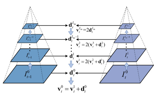
Figure 1.
Procedure of the pyramidal Lucas–Kanade (PLK) algorithm.
3. Hardware Architecture of Proposed Feature Tracker
Figure 2 shows the overall architecture of the proposed feature tracker. The proposed feature tracker detects the features from the first frame , and then tracks the features from the next frames , , , …, , where N is the frame number. The calculated motion vector for each frame is transferred to the UAV’s flight controller to perform hovering in real time. After tracking N frames, feature detection is performed again at frame , and then feature tracking is performed iteratively for subsequent frames, .
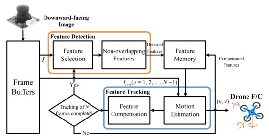
Figure 2.
Overall architecture of the proposed feature tracker.
Figure 3 shows a block diagram of the proposed feature tracker, which consists of a Hessian-matrix calculation unit (HCU), a feature detection unit (FDU), and a feature tracking unit (FTU). Because the Shi–Tomasi and PLK algorithms involve the same calculation of gradients and multiplications, the FDU and the FTU share the HCU to reduce hardware complexity. In addition, the HCU, FDU, and FTU are all designed with a pipelined structure for high-speed operation and lower memory usage.
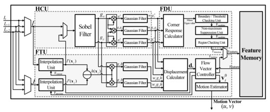
Figure 3.
Block diagram of the proposed feature tracker.
3.1. Hessian-Matrix Calculation Unit (HCU)
The HCU shown in Figure 3 consists of a Sobel filter and Gaussian filters. The HCU calculates matrix H in Equation (1) for the Shi–Tomasi algorithm and matrix G in Equation (9) for the PLK algorithm. The Sobel filter calculates the gradients in the horizontal and vertical directions, and the Gaussian filters smoothen these gradients using a Gaussian kernel. Gaussian and Sobel filters are implemented with a line buffer structure to carry out the convolution operation. The line buffer unit (LBU), which is shown in Figure 4, converts sequential input data to the form of an window. The LBU can be implemented without additional frame buffers because it reuses the input data line by line. The five Gaussian filters and the Sobel filter in the HCU, the two interpolation units in the FTU, and the NMS (non-maximum suppression) unit in the FDU were also implemented using LBUs. Consequently, the memory size was reduced from to , where and denote the horizontal and vertical resolutions of the input image, respectively.
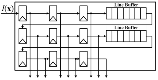
Figure 4.
Block diagram of line buffer unit (LBU).
3.2. Feature Detection Unit (FDU)
The FDU is composed of a corner-response calculation unit (CRCU), a boundary and threshold checking unit (BTCU), an NMS unit (NMSU), and a region checking unit (RCU). The CRCU determines the minor eigenvalue, which is a corner response. If the elements of the matrix H in Equation (1) are p, r, r, and q (in that order), the characteristic equation of H can be expressed as
By applying the quadratic formula to Equation (13), the minor eigenvalue is simply computed as
The BTCU selects points that have corner probabilities higher than a predefined threshold as feature candidates. In addition, the BTCU excludes feature candidates located at the boundary because these may be left out of the image during the tracking process.
After feature candidates are selected by the BTCU, the final features are selected by the NMSU and RCU. Because points close to good features typically have high corner responses, selected candidates can overlap. To avoid tracking essentially the same point multiple times, the NMSU and RCU enforce a minimum distance between features. The NMS technique picks only one feature with the best corner response in a window and then removes the remaining features that overlap with it and iterates [11]. Because iterating causes latency to increase, the NMSU is designed with a hardware-friendly structure using an LBU. As depicted in Figure 5a, the NMSU is composed of LBU and comparison units, which are shown in Figure 5b. Instead of carrying out a sorting process, NMS is performed by removing feature candidates when the input corner response is not the largest in the window. Subsequently, the RCU divides the image into k regions and selects the first candidate from the NMSU in each region as the final feature.
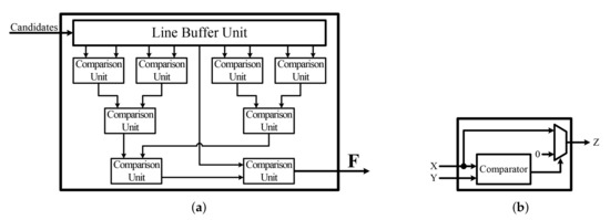
Figure 5.
Block diagrams of (a) the non-maximum suppression unit (NMSU) and (b) a comparison unit.
3.3. Feature Tracking Unit (FTU)
The FTU consists of interpolation units, Gaussian filters, a displacement calculator, a flow vector controller, and a motion estimator, as shown in Figure 3. The traditional PLK algorithm starts tracking from the highest-level image to the lowest-level image . However, because the pyramidal images are constructed in order from the lowest-level image to the highest-level image , performing decimation filtering to lower-level images as in Equation (11) requires additional memory to store the generated pyramidal images. Therefore, we use simple down-sampling instead of decimation filtering. Simple down-sampling enables the construction of an image pyramid without incurring additional processing time and memory by controlling the read address of the frame buffer according to the pyramidal level. Through experiments, we found that the degradation of the tracking performance when using down-sampling instead of decimation filtering is less than the root-mean-square error (RMSE) of one pixel.
The construction of pyramidal images via down-sampling is carried out in the interpolation unit. Figure 6 shows a block diagram of the interpolation unit, which consists of two blocks: a window region extractor (WRE) and a bilinear interpolator. The WRE operates as a read controller of frame buffers for the window centered on the feature corresponding to the current pyramidal level. The bilinear interpolator calculates the intensity value corresponding to the coordinate expressed as a real number via bilinear interpolation.
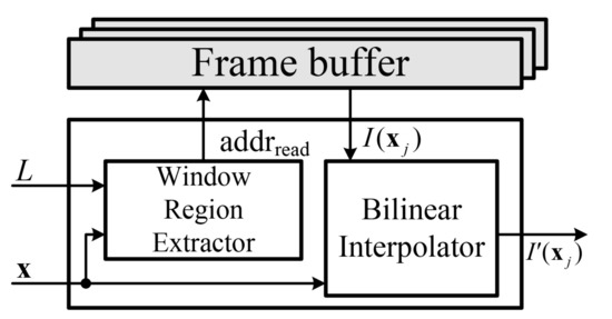
Figure 6.
Block diagram of the interpolation unit.
Figure 7 depicts the WRE, which calculates the read address of the frame buffer for down-sampling. If pixel data are stored in the frame buffer in the horizontal direction, the read address of the frame buffer is calculated as
and the address of each pyramidal level is connected to the multiplexer. The final read address is selected based on the current pyramidal level. x and y are the coordinates of the feature, and denote the row and column counter values, is the size of the window, is the vertical resolution, and L is the pyramidal level.
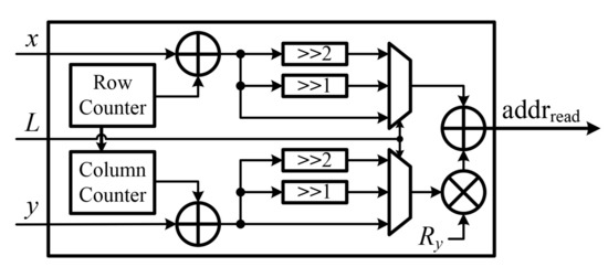
Figure 7.
Block diagram of the window region extractor.
The coordinates of the feature compensated by the calculated displacement are real numbers, not integers. Therefore, bilinear interpolation is required to determine the intensity of the pixel corresponding to the real number coordinates and achieve subpixel accuracy. Bilinear interpolation involves two linear interpolations, one in the horizontal direction and one in the vertical direction. Because a linear interpolation can be performed via a convolution operation with kernels determined by the coordinates of the features, the bilinear interpolator was designed using the LBU as shown in Figure 8.
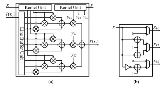
Figure 8.
Block diagram of (a) the bilinear interpolator and (b) a kernel unit.
After interpolation, the values of , g, and h are accumulated to obtain the elements of Equations (9) and (10). The displacement calculator then calculates d as the product of a vector and an inverse matrix, as shown in Figure 9.
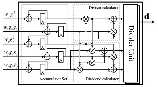
Figure 9.
Block diagram of the displacement calculator.
To calculate the inverse matrix, division by the determinant of is required. Because the division operation is highly complex, we use an efficient divider unit considering the characteristics of the proposed feature tracker, as shown in the flowchart in Figure 10. Here, z is the dividend, d is the divisor, is the integer part of the quotient, is the decimal part of the quotient, and f is the number of decimal places. The latency of this divider unit is proportional to the size of the quotient. However, because the value of each element of the displacement vector is less than n when the size of the search window is , the latency of the divider unit is within () clock cycles, which is approximately 10 clock cycles. Therefore, the divider unit can be implemented with approximately 35% less area than the general divider unit in [20] using shifters and an adder without causing performance degradation.
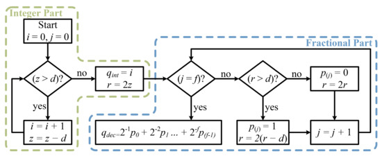
Figure 10.
Flowchart of the divider unit.
After the calculation of the displacements, the feature memory is iteratively updated via the summation of the displacement and the stored coordinates of features. The final motion vector of a feature is then calculated by performing a pyramidal propagation from level L to level 0. After the tracking process for all features is performed, the tracking process is repeated for the next frame.
To calculate , which is the motion vector of a single value, from several flow vectors, a motion estimator based on a histogram is used. The motion estimator analyzes the histogram of the flow vectors. The histogram is generated by dividing the entire range of the flow vectors into a series of intervals and then counting how many vectors fall into each interval [21].
4. FPGA Implementation Results
The proposed feature tracker was designed using Verilog, a hardware description language, and implemented on a Xilinx Virtex7 XC7VX330T FPGA device [22]. Thus, the proposed feature tracker was implemented with 2744 slices, 7459 slice LUTs, 25 DSPs, and a 93 Kbit block RAM. Its power consumption is 108 mW at a maximum operation frequency of 130 MHz, as shown in Table 1.

Table 1.
Implementation results of the proposed feature tracker.
A comparison of the FPGA resources required for the proposed feature tracker and those of previous works [23,24,25] is presented in Table 2. The tracker proposed in [25] for embedded vision applications can extract and track features at very high speeds by making the inter-frame displacement very small. This approach significantly reduces the time required to extract all features and exhibits comparable performance with the proposed design in terms of the number of maximum features and normalized execution time. However, compared with [25], the proposed feature tracker can reduce the maximum number of slices by 56%, slice LUTs by 65%, and block RAM by 97%. This is because the HCU is fully shared, several computations (such as division and minor eigen value calculation) are simplified, and the pipeline structure was designed without additional block RAM. Even though the design proposed in [23] requires fewer hardware resources, it was implemented without the pyramidal scheme.

Table 2.
Comparison of the proposed tracker and previous works.
Table 3 shows the comparison results in terms of processing speed. To make a fair comparison, we normalized the execution time as time per pixel at a clock frequency of 60 MHz. As shown in Table 3, the execution time per pixel and feature of the proposed feature tracker is lowest among the different trackers considered owing to its pipelined structure and pyramidal image construction with no latency. In addition, the proposed tracker can track more features than those of previous works at the same resolution. Moreover, the execution time per feature of the proposed tracker is also lowest. Therefore, the proposed tracker is well suited for autonomous hovering of UAVs because it can support a good tracking performance with low hardware complexity and high processing speed, as evidenced in Table 2 and Table 3.

Table 3.
Comparison of the processing speed of our approach with previous works.
5. Experiment Results
To evaluate the performance of the proposed feature tracker, we used the DJI Phantom 4 [26]. Performance evaluations were performed by comparing the trajectory of motion vectors obtained from the proposed feature tracker based on the images from the downward-facing camera with the movement trajectory derived from GPS coordinates information from the DJI Phantom 4.
Because the unit of the motion vector of the proposed feature tracker is pixels and that of the GPS-based movement trajectory is meters, it is necessary to convert the former to meters as follows:
where H is the altitude of the drone and is the focal length, which is the distance from the camera’s projection center to the image sensor [27]. Subsequently, the movement trajectory of the UAV was calculated based on the histogram of the motion vectors expressed in meters. The red boxes indicate the position of the features in the previous frame, and the yellow lines indicate the flow vectors. The green arrow indicates a representative vector calculated from the histogram of the flow vectors. When the motion vector is (−0A, FE) in hexadecimal, we can derive that the UAV is moving at a speed of 2.13 cm per frame using Equation (16), as shown in Figure 11.
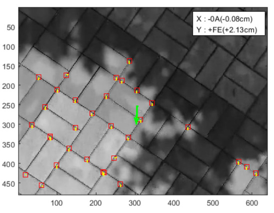
Figure 11.
Motion vector in metric units.
The experiment was conducted using images obtained by flying for approximately 10 s at an altitude of 2 m on lawn, asphalt, and sidewalk block environments. For comparison with GPS-based trajectories, we unavoidably conducted experiment in outdoor environments. Table 4 summarizes the verification environments.

Table 4.
Summary of verification environments.
Figure 12 shows the trajectories obtained by accumulating the metric moving distance of the proposed feature tracker and the movement trajectory of the Phantom 4 obtained based on the GPS coordinates. The proposed design tracks a moving path similar to the GPS-based results in each environment. Table 5 shows the RMSE normalized by moving distance of the results obtained using the proposed feature tracker and a GPS-based approach. The proposed feature tracker exhibited a similar performance with an average normalized RMSE of 0.039. Therefore, the proposed feature tracker should be able to support the hovering of UAVs even in GPS-denied environments, such as indoor environments.

Figure 12.
Comparison of the proposed feature tracking results with GPS-based results on (a) lawn, (b) asphalt, and (c) sidewalk blocks.

Table 5.
Normalized root-mean-square error (NRMSE) of the proposed feature tracker.
6. Conclusions
In this paper, we proposed an area-efficient hardware architecture to perform feature tracking to support the autonomous hovering of UAVs. We present a fast and area-optimized hardware design based on a robust and accurate pyramidal KLT algorithm. To reduce the area of the feature tracker, we leveraged the fact that the PLK and Shi–Tomasi algorithms share certain computations. The feature tracker was implemented with 2744 slices, 7459 slice LUTs, 25 DSPs, and 93 Kbit of on-chip memory on a Xilinx Virtex7 XC7VX330T device, which represents a reduction in the number of maximum slices of 56%, slice LUTs of 65%, and block RAM of 97% compared with existing feature tracker implementations. We experimented in various flight environments to verify our implementation, and we confirmed that the proposed feature tracker consistently tracks the motion of the drone with GPS-based trajectories. The proposed feature tracker supports real-time processing at 417 FPS and an operating frequency of 130 MHz for VGA images (640 × 480).
Author Contributions
H.K. designed the algorithm, performed the hardware architecture design and simulation and wrote the paper. J.C. conducted the hardware design and experiments. Y.J. (Youngchul Jung) and S.L. performed the implementation on FPGA and revised the manuscript. Y.J. (Yunho Jung) conceived and led the research, analyzed the experimental results, and wrote the paper. All authors have read and agree to the published version of the manuscript.
Funding
This work was supported by the Technology Innovation Program 10080619, funded by the Ministry of Trade, Industry and Energy (MOTIE, Korea) and CAD tools were supported by IDEC.
Acknowledgments
The authors would like to thank the anonymous reviewers for their constructive and helpful comments and suggestions.
Conflicts of Interest
The authors declare no conflict of interest.
References
- Menouar, H.; Tuncer, A. UAV-enabled intelligent transportation systems for the smart city: applications and challenges. IEEE Commun. Mag. 2017, 55, 22–88. [Google Scholar] [CrossRef]
- Scaramuzza, D.; Achtelik, M.C.; Doitsidis, L.; Friedrich, F.; Kosmatopoulos, E.; Martinelli, A.; Gurdan, D. Vision-controlled micro flying robots: from system design to autonomous navigation and mapping in GPS-denied environments. IEEE Robot. Autom. Mag. 2014, 21, 26–40. [Google Scholar]
- Gatica, Z.N.; Munoz, P.C.; Sellado, A.P. Real fuzzy PID control of the UAV AR. Drone 2.0 for hovering under disturbances in known environments. In Proceedings of the 2017 CHILEAN Conference on Electrical, Electronics Engineering, Information and Communication Technologies (CHILECON), Pucon, Chile, 18–20 October 2017; pp. 1–6. [Google Scholar]
- He, R.; Prentice, S.; Roy, N. Planning in information space for a quadrotor helicopter in a GPS-denied environment. In Proceedings of the 2008 IEEE International Conference on Robotics and Automation, Pasadena, CA, USA, 19–23 May 2008; pp. 1814–1820. [Google Scholar]
- Arreola, L.; de Oca, A.M.; Flores, A.; Sanchez, J.; Flores, G. Improvement in the UAV position estimation with low-cost GPS, INS and vision-based system: Application to a quadrotor UAV. In Proceedings of the 2018 International Conference on Unmanned Aircraft Systems (ICUAS), Dallas, TX, USA, 12–15 June 2018; pp. 1248–1254. [Google Scholar]
- Rawashdeh, N.A.; Rawashdeh, O.A.; Sababha, B.H. Vision-based sensing of UAV attitude and altitude from downward in-flight images. J. Vib. Control 2017, 23, 827–841. [Google Scholar] [CrossRef]
- Fowers, S.G.; Lee, D.J.; Tippetts, B.J.; Lillywhite, K.D.; Dennis, A.W.; Archibald, J.K. Vision aided stabilization and the development of a quad-rotor micro UAV. In Proceedings of the 2007 International Symposium on Computational Intelligence in Robotics and Automation, Jacksonville, FL, USA, 20–22 June 2007; pp. 143–148. [Google Scholar]
- Gageik, N.; Strohmeier, M.; Montenegro, S. An autonomous UAV with an optical flow sensor for positioning and navigation. Int. J. Adv. Robot. Syst. 2013, 10, 341. [Google Scholar] [CrossRef]
- Ahrens, S.; Levine, D.; Andrews, G.; How, J.P. Vision-based guidance and control of a hovering vehicle in unknown, GPS-denied environments. In Proceedings of the 2009 IEEE International Conference on Robotics and Automation, Kobe, Japan, 12–17 May 2009; pp. 2643–2648. [Google Scholar]
- Achtelik, M.; Bachrach, A.; He, R.; Prentice, S.; Roy, N. Autonomous navigation and exploration of a quadrotor helicopter in GPS-denied indoor environments. In Proceedings of the First Symposium on Indoor Flight, Mayagüez, Puerto Rico, July 2009. [Google Scholar]
- Tomasi, C.; Kanade, T. Detection and Tracking of Point Features. Int. J. Comput. Vis. 1991, 9, 137–154. [Google Scholar]
- Shi, J. Good features to track. In Proceedings of the 1994 IEEE Conference on Computer Vision and Pattern Recognition, Seattle, WA, USA, 21–23 June 1994; pp. 593–600. [Google Scholar]
- Siong, L.Y.; Mokri, S.S.; Hussain, A.; Ibrahim, N.; Mustafa, M.M. Motion detection using Lucas Kanade algorithm and application enhancement. In Proceedings of the 2009 International Conference on Electrical Engineering and Informatics, Bangi, Malaysia, 5–7 August 2009; pp. 537–542. [Google Scholar]
- Antonakos, E.; Alabort-i-Medina, J.; Tzimiropoulos, G.; Zafeiriou, S.P. Feature-based lucas-kanade and active appearance models. IEEE Trans. Image Process. 2015, 24, 2617–2632. [Google Scholar] [CrossRef] [PubMed]
- Pearce, S.; Ljubičić, R.; Peña-Haro, S.; Perks, M.; Tauro, F.; Pizarro, A.; Dal Sasso, S.F.; Strelnikova, D.; Grimaldi, S.; Maddock, I.; et al. An Evaluation of Image Velocimetry Techniques under Low Flow Conditions and High Seeding Densities Using Unmanned Aerial Systems. Remote. Sens. 2020, 12, 232. [Google Scholar] [CrossRef]
- Ma, S.; Bai, X.; Wang, Y.; Fang, R. Robust Stereo Visual-Inertial Odometry Using Nonlinear Optimization. Sensors 2019, 19, 3747. [Google Scholar]
- Ci, W.; Huang, Y. A robust method for ego-motion estimation in urban environment using stereo camera. Sensors 2016, 16, 1704. [Google Scholar] [CrossRef] [PubMed]
- Auysakul, J.; Xu, H.; Pooneeth, V. A hybrid motion estimation for video stabilization based on an IMU sensor. Sensors 2018, 18, 2708. [Google Scholar] [CrossRef] [PubMed]
- Bouguet, J.Y. Pyramidal implementation of the affine lucas kanade feature tracker description of the algorithm. Int. Corp. 2001, 5, 4. [Google Scholar]
- Available online: https://www.xilinx.com/support/documentation/ip_documentation/div_gen/v5_1/pg151-div-gen.pdf (accessed on 28 September 2020).
- Cho, J.; Jung, Y.; Kim, D.S.; Lee, S.; Jung, Y. Moving object detection based on optical flow estimation and a Gaussian mixture model for advanced driver assistance systems. Sensors 2019, 19, 3217. [Google Scholar] [CrossRef] [PubMed]
- Available online: https://www.xilinx.com/support/documentation/selection-guides/virtex7-product-table.pdf (accessed on 28 September 2020).
- Ham, Y.C.; Shi, Y. Developing a smart camera for gesture recognition in HCI applications. In Proceedings of the 13th IEEE International Symposium on Consumer Electronics (ISCE), Kyoto, Japan, 25–28 May 2009; pp. 994–998. [Google Scholar]
- Jang, W.; Oh, S.; Kim, G. A hardware implementation of pyramidal KLT feature tracker for driving assistance systems. In Proceedings of the 2009 12th International IEEE Conference on Intelligent Transportation Systems, St. Louis, MO, USA, 4–7 October 2009; pp. 1–6. [Google Scholar]
- Chai, Z.; Shi, J. Improving KLT in embedded systems by processing oversampling video sequence in real-time. In Proceedings of the 2011 International Conference on Reconfigurable Computing and FPGAs, Cancun, Mexico, 30 November–2 December 2011; pp. 297–302. [Google Scholar]
- Available online: https://www.dji.com/phantom-4 (accessed on 28 September 2020).
- Frietsch, N.; Meister, O.; Schlaile, C.; Seibold, J.; Trommer, G. Vision based hovering and landing system for a vtol-mav with geo-localization capabilities. In Proceedings of the AIAA Guidance, Navigation and Control Conference and Exhibit, Honolulu, HI, USA, 18–21 August 2008; p. 6669. [Google Scholar]
© 2020 by the authors. Licensee MDPI, Basel, Switzerland. This article is an open access article distributed under the terms and conditions of the Creative Commons Attribution (CC BY) license (http://creativecommons.org/licenses/by/4.0/).