1. Introduction
Nowadays, with the declining production of fossil and coal sources, a growth of interest in investigating renewable energy resources has been conceived. The Earth’s climate has changed and many human activities are changing the natural greenhouse. Over the last century, the burning of fossil fuels like coal and oil has increased the concentration of atmospheric carbon dioxide (CO
) due to the industrial activities that our modern civilization depends upon. The world’s power demand is increasing, therefore, the demand for solar power is increasing rapidly and it acts an important role in replacement of conventional fuels. The power from the sun is a green choice, to solve the problem of traditional fuel limitations because it is freely available. Hence, several small power photovoltaic generation systems have been expected to be installed on private residences. These solar panels are expected to satisfy some requirements such as lifetime, reduction in cost, and efficiency [
1]. Presently single-phase inverters are broadly used in photovoltaic (PV) power applications. They can be in stand-alone operation or grid-connected; however, the output terminal voltage should be maintained at a constant level with minimum harmonics. The grid-connected PV is divided into two categories such as with a transformer and without a transformer. A solar panel using a transformer has galvanic isolation which increases the security and provides no further DC current toward the grid. It also decreases the leakage current between the PV and grid, however, it is expensive, heavy, and large. The galvanic isolation can be used for a high-frequency transformer. In many applications, high-frequency transformers are employed due to the high power density [
2]. On the other hand, the transformerless photovoltaic systems have high efficiency and they are cheaper and have a smaller size [
3,
4,
5,
6]. The foremost purpose of the transformerless inverter is to maximize efficiency, performance, and reliability as opposed to the other configuration. In addition, the aim is to reduce the leakage of current, because when the transformer is eliminated from the system, the parasitic capacitance between PV and ground may inject leakage of current. Several modulation techniques have been introduced to overcome the problem of current leakage and avoid DC injection into the grid. The output of a photovoltaic (PV) module is a DC voltage that cannot be applied directly to the AC load, therefore, an inverter is required to generate alternative voltage, and also a filter to smooth the output voltage and current. A pure sine wave is desired at output voltage but PV panels generate a varied output voltage due to changing in irradiance. Thus, a proportional integral derivative (PID) controller is used to obtain constant DC voltage.
The inverter output voltage contains harmonics that can be reduced by applying output filters as well as PWM. Accordingly, several pulse width modulation (PWM) methods are used to generate the gate pulses for constant DC supply and reduce the harmonics. The cost and size of the output filter are reduced by using the PWM method. On the other hand, it is necessary to control the switches by providing gate pulses. Different PWM techniques are presented in the literature, such as single pulse width modulation [
7], multiple pulse width modulation, sinusoidal pulse width modulation (SPWM) [
8], space-vector PWM (SVPWM) [
9] and selective harmonic elimination PWM (SHEPWM) [
10]. The sinusoidal pulse width modulation can be divided into two categories such as unipolar and bipolar. In power systems, minimum harmonics are desired because they may cause reduced torque in motors, voltage stress in capacitors, and extreme heating. Harmonics mean a root-sum-square of the sum of the squares of different frequency components as shown in Equation (
1).
where V
is the RMS voltage of the
harmonic and
is the fundamental frequency. Based on IEEE 519, harmonic voltage distortion on power systems 69 kV and below is 5% total harmonic distortion (THD), with an individual harmonic of 3% [
11]. In
Table 1, the IEEE 519 harmonic voltage limits is presented.
Generally, single-phase inverters generate power pulsation, resulting in a ripple voltage on the DC bus; this phenomenon will decrease the average power from the PV panel. To overcome this problem, an electrolyte capacitor with large capacitance may be an alternative to DC input. However, the large capacitor has a bulky size and shorter lifetime. The alternative is to use a boost converter to feed the inverter to obtain maximum power point tracking (MPPT). Therefore, the DC link capacitor can be minimized. As a result, film capacitors can be applied alternatively. In addition, the replacement of film capacitors with electrolytes will increase the lifetime of the inverter.
2. Direct Usage of Photovoltaic Solar Panels to Supply a Freezer
Today, there is a tendency to look also at direct use of PV-panels, without injecting in the grid and without storing in a battery. The PV panels are usually intended to inject into the grid. However, the grid injection feature is not available at a local. Even if several kW PV is potentially available, it is not possible to operate a freezer that needs only power of about 50–100 W it in the winter. The paper aims to build a single-phase inverter, matching home freezers starting from a normal PV array with some point of attention:
- −
Work with low no-load, a DC voltage applied at no-load.
- −
Operate without battery.
- −
Have enough energy in the DC-link capacitor to get the motor started.
- −
No filtering circuit at the output of the inverter.
- −
No grid connection will result in no leakage current between the PV and Grid.
Simple inverters, such as square wave and modified sine wave are not good enough for motors. However, some harmonics or imperfections can be tolerated. A modulated DC-link could be an option and creates a rectified sine wave, based on a microcontroller. The differences between the proposed solution and others are the following:
- −
DC-link instead of AC link. This fact reduces no-loads, have a lower BOM and have a much higher efficiency.
- −
No battery in the system. Reduce the price of the installation, approximating the target of how to get it in a realistic and cost-effective way.
- −
Electrolytic capacitor to have enough energy in the DC-link to get the motor started. 0.3 s to start and if the solar energy gives 40 W the circuit can work properly.
- −
No grid connection will result in no leakage current between the PV and Grid.
3. The Proposed Single-Phase PV Inverter Fed by a Boost Converter
The world power consumption is increasing at a high rate; moreover, non-renewable sources are decreasing; therefore, alternative energy sources have become an important concern. Accordingly, there has been an interest in stand-alone generating systems based on renewable energy [
12], especially PV systems for home applications. Regarding home applications, stand-alone photovoltaic systems provide electrical energy to power lights, water pump, freezers, and several other purposes [
13,
14]. Reference [
15] investigates a battery management system (BMS) for stand-alone photovoltaic (PV) energy systems. It calculates the state of charge (SOC) of a lead–acid battery to determine the capacity over time, but it is not suitable for other battery types. In [
16], the optimal sizing of stand-alone PV stations is discussed. It evaluates different PV schemes considering the stochastic natures of the insolation and the load. However, it requires batteries. The design, modeling, sizing, and control of a photovoltaic stand-alone hole to vehicle application that can fully charge the battery electric vehicle overnight at home is investigated in [
17]. In [
18], A stand-alone PV supercapacitor battery hybrid energy storage system is studied. The paper claims that a burst current at startup which results in battery degradation is supplied by combination of valve regulated lead-acid batteries and supercapacitors. Still, it requires a battery and supercapacitors. Reference [
19] investigates an AC-linked hybrid wind/PV/fuel cell energy system for a stand-alone application to manage power flows among the different energy sources. A review of the maximum power point tracking algorithms for stand-alone photovoltaic systems is studied in [
20]. A survey of the algorithms for investigating the maximum power point (MPP) is offered. Similarly, in [
21], a comparative study of a low-cost maximum power point tracker (MPPT) and the conventional configurations of the photovoltaic (PV) regulators under different atmospheric conditions are given. It is made using the energy production obtained by the PV generator of each system. References [
22,
23] present an analysis of the PV energy capacity and economy of stand-alone residential applications.
A proposed single-phase photovoltaic inverter fed by a boost converter to supply a freezer with variable DC input is presented in this paper.
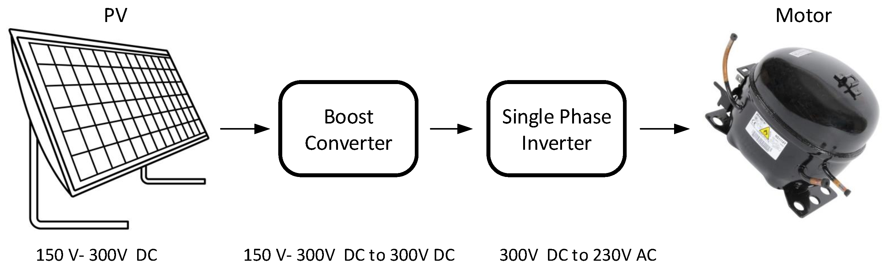
The proposed system overcomes the problem of galvanic isolated and transformerless PV systems because it is not connected to the grid. The system also does not require an LC output filter because the motor can operate with pulsated output voltage and the electrolyte capacitors own a lower life cycle. In addition, it does not necessitate complex PWM methods to reduce harmonics. The proposed topology consists of four main items:
- −
PV Panels: To transform solar energy intro electrical energy with a range of voltages of 150–300 V DC.
- −
DC/DC converter: To adapt the Vinput of 150–300 V DC to Voutput of 300 V DC with a current Iout between 1.66 and 2 A working with a frequency of 40 kHz. An electrolytic capacitor that store enough energy to get the motor started is included in the converter circuit.
- −
Bridge inverter: To create an AC sine wave based on microcontroller with a particular type of timing for pulses. The voltage and PWM edge frequency are limited not to blow up the internal power supply for the control of the freezer and limited harmonics in the motor no to damage the internal power supply of the freezer.
- −
Freezer Motor: AC Motor that needs a supply of about 230 V fundamental voltage at the input of the circuit.
The differences between the proposed solution and others are the following:
- −
DC-link instead of AC link. This fact reduces no-loads, have a lower bill of material (BOM) and have a much higher efficiency.
- −
No battery is present in the system. It reduces the price of the installation, approximating the target of how to get it in a realistic and cost-effective way.
- −
An electrolytic capacitor to have enough energy in the DC-link to get the motor started. 0.3 s to start and if the solar energy gives 40 W the circuit can work properly.
In
Figure 1, the schematic of the proposed PV panel to supply a freezer with variable DC input is presented. It can be seen in the figure that the PV panels will generate the input DC voltage. This voltage can vary from 150 V–300 V. Next, the boost converter converts this voltage to a fixed DC voltage of 300 V. Then the boost converter feeds the single-phase full-bridge inverter to generate 230 V AC which is desirable to supply the freezer.
4. The Boost Converter
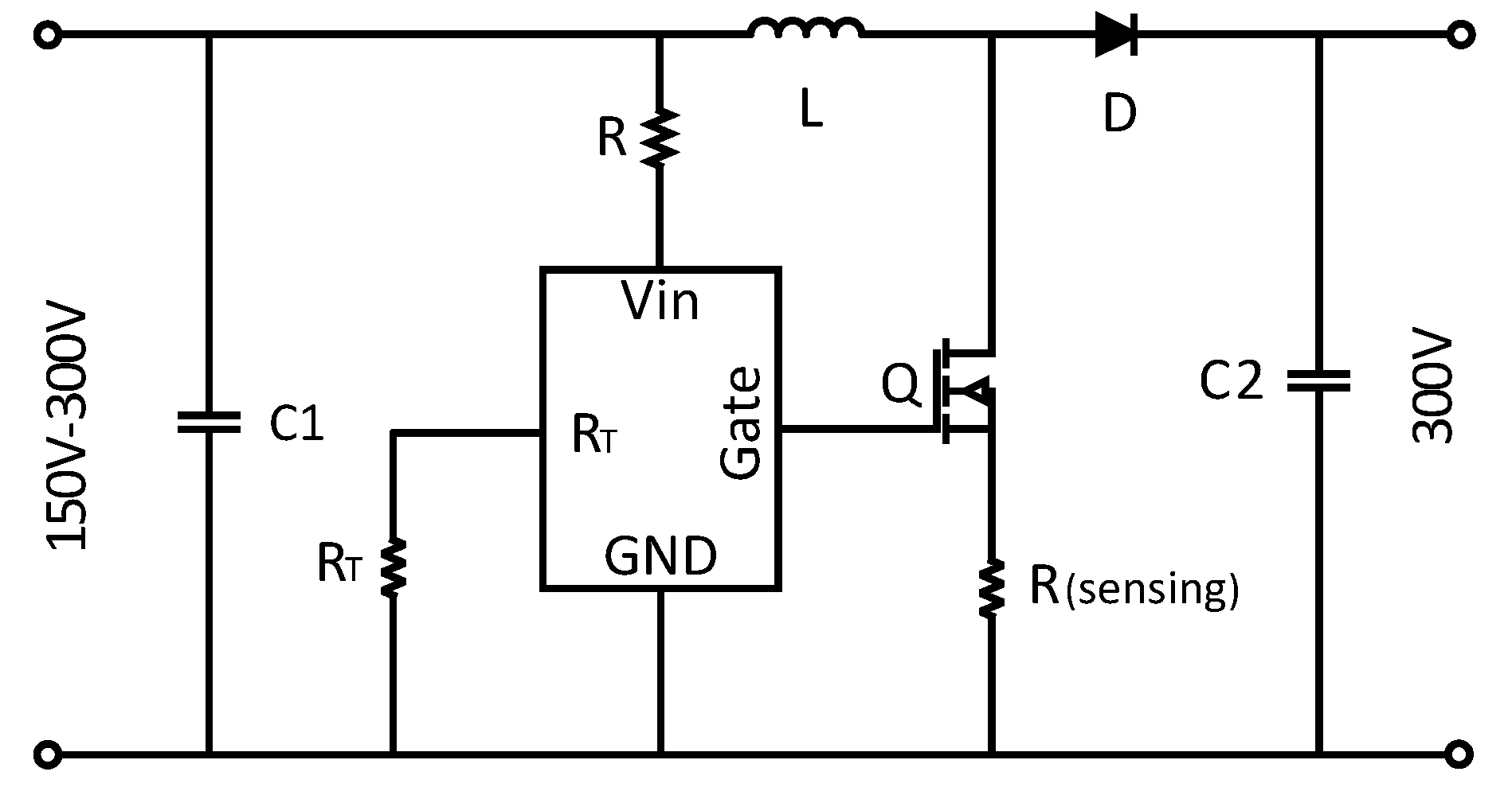
The boost converter is a mechanism of power transmission to perform energy absorption and injection from solar panel to grid. The output voltage of the photovoltaic system will very depending on sun irradiation and temperature, therefore, a boost converter is essential to obtain a fixed DC voltage. The proposed boost converter contains an electrolytic capacitor (C2) to supply the energy that is required to get the motor started. The converter has a film filter capacitor (C1) at the input to smooth the input voltage. The converter uses a self oscillating driver with feedback to obtaining a fixed output voltage. The driver can work with different voltage input. The switch is an N-channel MOSFET controlled by PWM determined by R
. The schematic of the boost converter circuit is shown in
Figure 2.
Some converters need to convert a DC voltage in another DC voltage without galvanic separation. The word “chopper” is used for DC–DC converters. Depending on the application, very different output ripples are allowed. For power supply applications it is usually required that a low ripple of 1% or lower is obtained. Other applications like DC machines, batteries, galvanization, welding with DC, allow a lot of DC voltage ripple or current ripple. To design the boost converter, some important parameters should be considered such as duty cycle, inductor value, and capacitor value. According to the volt-second balance, the duty cycle of the boost converter can be expressed as:
where
D is the duty cycle, and
V and
V are output and input voltages respectively. The critical inductor
L which is the minimum of inductor for the boost converter to operate in continues conduction mode (CCM) can be calculated as
The boost converter critical capacitor which is the minimum capacitor to obtain the desired output voltage ripple can be expressed as
In practical application, the output voltage ripple is considered to be 1% of the output voltage. To produce a constant current, a current control system is used. In this control system, the resistor R will measure the current and the driver will generate the PWM signal to the MOSFET. The inductor and capacitor values should be higher than the calculated value to operate in CCM. Also, capacitor series resistance (ESR) should be small. The capacitor series resistor ESR affects efficiency, therefore, a low-ESR capacitor is desired for the best performance.
5. The Full Bridge Inverter
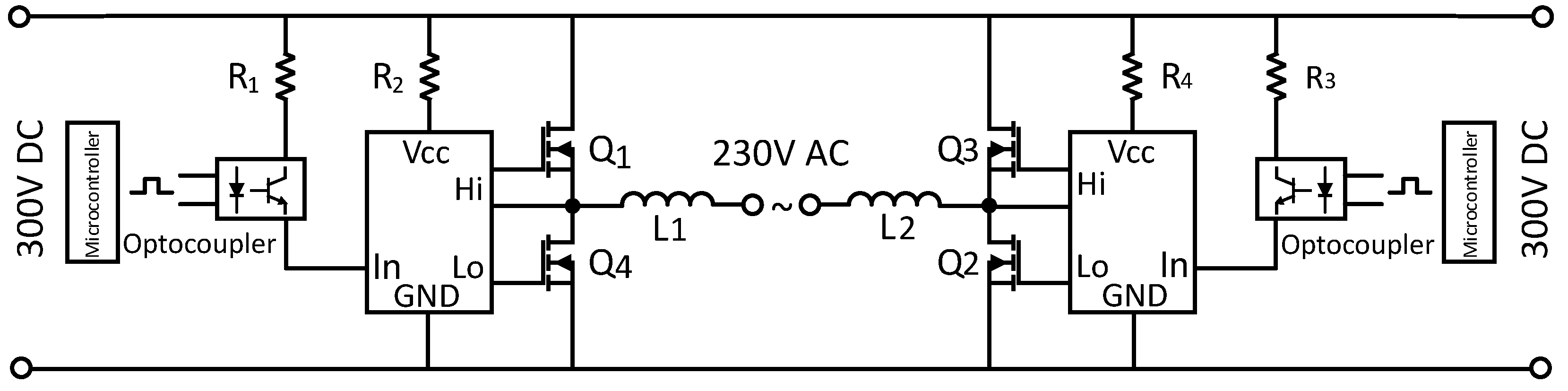
In this section, the operation principle of the full-bridge single phase inverter will be discussed. A full bridge converter belongs to the group of DC/DC converters with galvanic separation. The bridge converter uses active switching components in a configuration across a power transformer. This has lower losses than a bridge rectifier. The entire circuit will be a DC-link between the solar panels and the induction motor. An inverted DC to AC signal is required by the AC motor. This inverted signal is generated by a microcontroller to obtain desired AC pulses. In
Figure 3, the schematic of the full bridge inverter is presented.
The proposed full bridge single phase inverter circuit consists of four active switching devices. These switches are N-channel MOSFETs with body diodes, to drive the circuits. The switching waveform could be either square or sinusoidal, however, a square wave is simpler to implement, it has more harmonic content; some of them can be tolerated. To achieve high performance of the AC drive system multilevel inverters are essential to ensure low current harmonic distortion and torque pulsation. In a multi-level inverter, the number of switching devices is proportional to the level of the output voltage. There are many types of PWM in the literature such as single phase-three level inverter [
24,
25,
26], five-level inverter [
27,
28], and seven-level inverter [
29,
30]. The three-level inverters have high efficiency, but they pose the problem of neutral point voltage discharging of output capacitors. The proposed single-phase full-bridge two-level inverter uses two pulses to control the switches. The pulses are generated based on the use of timing shown in
Table 2.
The operational principle involves switching one pair of transistors at a time for a one-half cycle and the other pair during the other half cycle. The control strategy uses the pulse width modulation (PWM) signal to the MOSFETs on each leg simultaneously with a complimentary pattern. With this type of square wave shown in
Table 2, the 5th and 7th harmonics of the voltage will be reduced. The period of 20 ms is desired to obtain a frequency of 50 Hz for the motor. Therefore, the timing period which is 20 ms is divided by 30 pints, thus, each point indicates 666
s. To generate the desired pulses, 13 numbers of timings, On/Off are required. These pulses are first applied to the optocoupler to isolate the control signal with the entire circuit. The created pulses will be applied to the drivers which are half-bridge drivers. The output of the drivers will be inverting and non-inverting signals to control the MOSFETs. Finally, the pulsate output voltage feeds the motor which is a single-phase induction motor.
6. Simulation Results
In this section, the simulation is made in MATLAB and the results are given to verify the viability of the proposed topology. Firstly, the output voltage of the PV panels which are of DC voltage that varies between 150 and 300 V DC is applied to the boost converter. The input voltage steps up to a fixed voltage of 300 V DC which is suitable to connect to the next stage. Then, the voltage feeds the single-phase full-bridge inverter. The switches are MOSFETs with a body diode, and they are controlled with PWM generated by a pulse generator according to the timing shown in
Table 2. The frequency of the PWM pulses is 50 Hz.
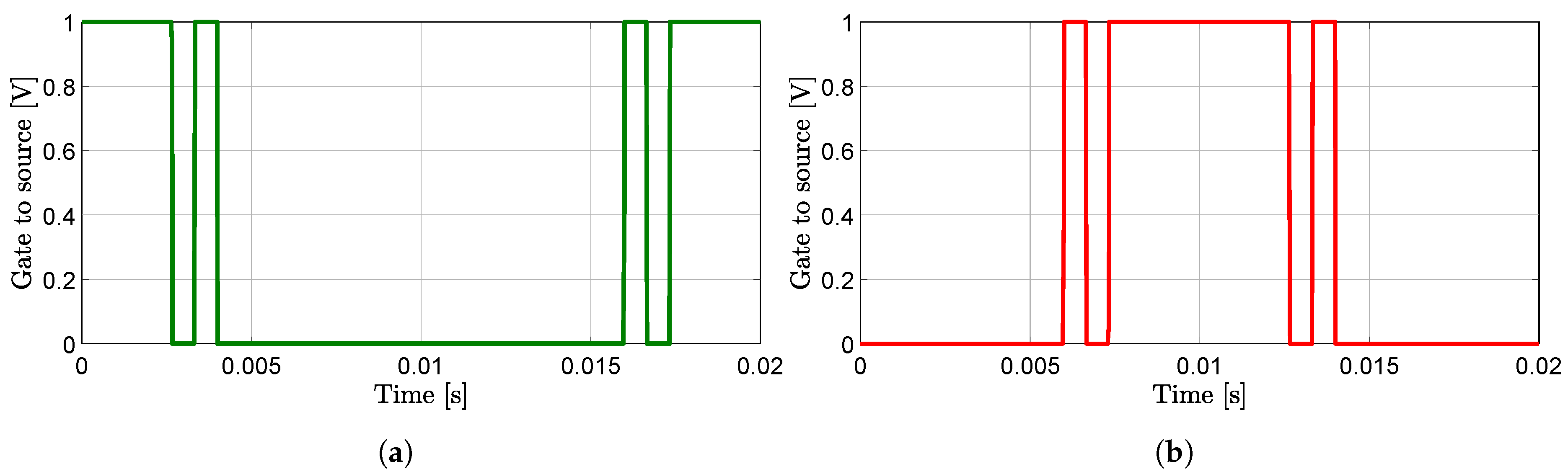
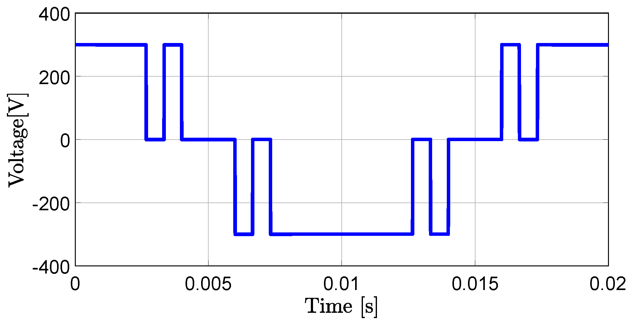
Figure 4a,b show the gate to source voltage to Q1, Q2 and gate to source voltage to Q3, Q4, respectively. The control strategy is in such a way that the switches Q1 and Q2 will be turned on together and then the switches Q3 and Q4. The switches Q1 and Q4 as well as Q2 and Q3 should not be conducted at the same time due to shorting the legs. The output generated pulses will feed the freezer motor. To model the motor, a single-phase asynchronous machine was investigated at the inverter output. The nominal power is 100 W, voltage is 230 V and frequency is 50 Hz. The generated pulses based on
Table 2 are applied to the switches, and the legs output voltages are shown in
Figure 5.
The pulsated output voltage will run the motor because the induction motor can operate with pulsating voltages. Therefore, there is no need for the out filter and this results in no output capacitors. The output capacitors which are electrolyte capacitors cause the circuit to be bulky and expensive. In addition, electrolyte capacitors have a shorter lifetime and higher equivalent series resistance as compared to film capacitors. The proposed scheme does not require a capacitor at the output of the inverter.
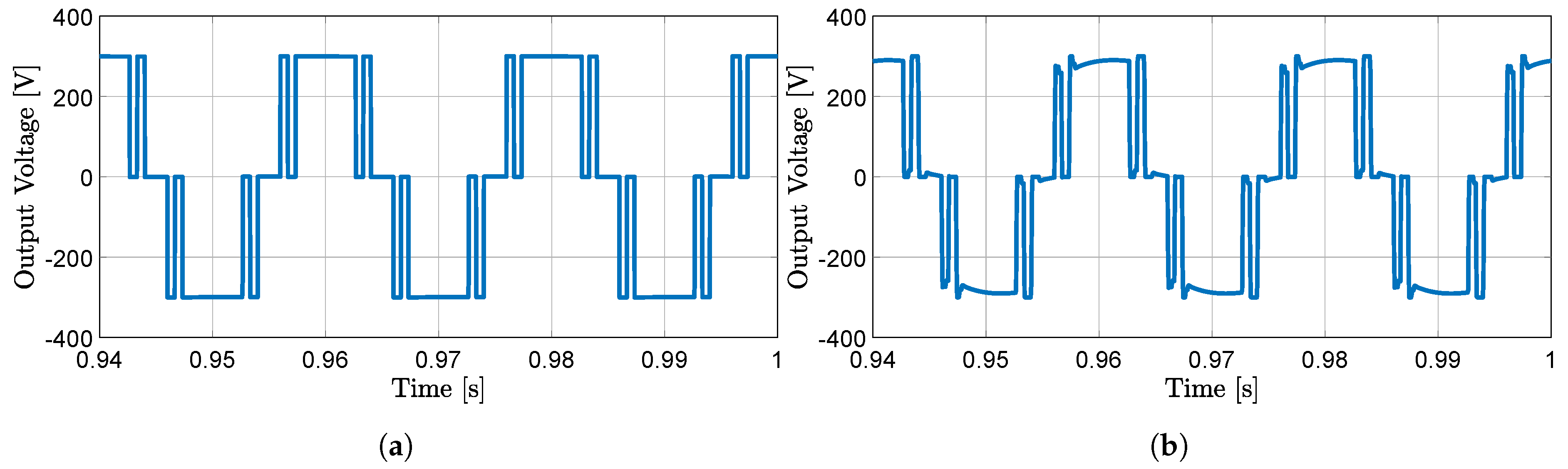
In
Figure 6a, the inverter output voltage at no load condition in steady-state is presented. It can be noticed that the waveform has no distortion. The load voltage in steady-state when the motor is connected to the inverter output is presented in
Figure 6b. It can be seen that there is a distortion presented in the waveform due to the motor.
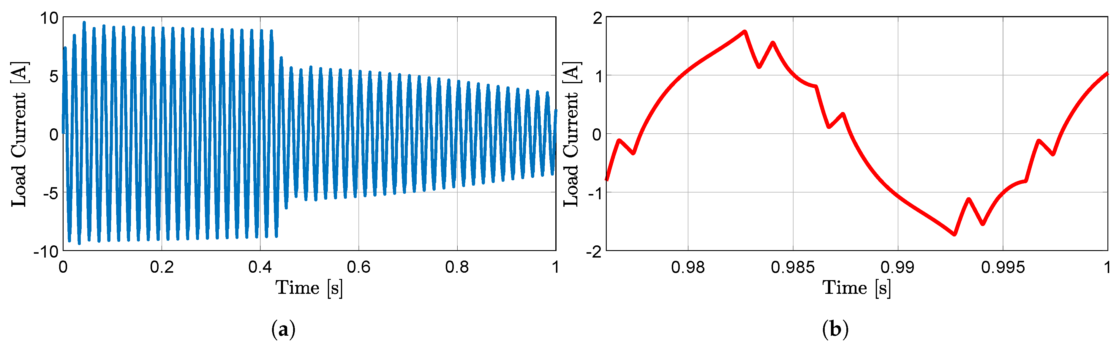
In
Figure 7a, The motor current in transient (start-up) is shown. It can be seen in the figure that, in transient, the motor required around 10 A to start, then in steady-state, the current will be reduced to 3.3 A. The motor current in steady-state in a closer view is presented in
Figure 7b. The waveform is tended to be sinusoidal because of the load which is an inductive load.
As it has been discussed before, the generated pulses will eliminate the harmonics (5th and 7th). Therefore, to prove the estimated concept, the Fourier series of the waveform is calculated. A more compact way of writing the Fourier series of a function
, with period
T, uses the variable subscript
.
The angular frequency
can be expressed as
. The fourier coefficients
,
and
for given function
can be written as
The generated pulse to the driver as shown in
Figure 5 has no DC value
, because the waveform has both symmetric positive and negative values resulting in
. Also, the
coefficients are zero, because it is an even function. The fourier coefficients
–
are presented in
Table 3.
As can be seen in
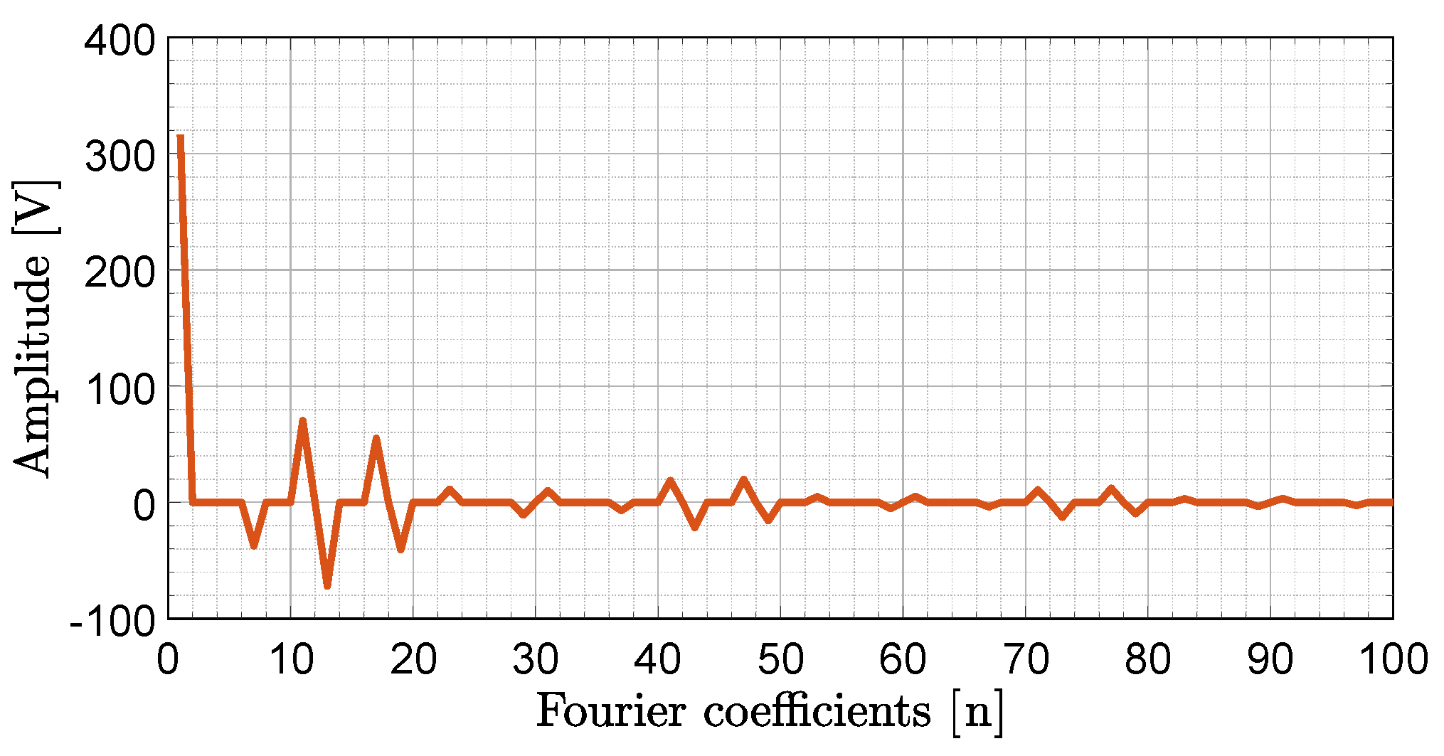
Table 3, all even harmonics are zero, and odd harmonics (3rd to 9th) are eliminated. The generated pulse, as shown in
Figure 5, is similar to a cosine waveform. A cosine function is an even function, which means
coefficients are zero. To possess a more extensive view of the harmonics, the harmonics (1st to 100th) are calculated, and the results are presented in
Figure 8.
A voltage or current which is purely sinusoidal owns no harmonic distortion because it is a signal consisting of a single frequency. A voltage or current which is periodic but not purely sinusoidal contains higher frequency components in it contributing to the harmonic distortion of the signal.
The use of the used pulse with modulated waveform has the advantage of reducing the 5th and all multiples of 3rd harmonics of the voltage wave, having a quite low total harmonic distortion in load current and as a result, having a waveform with higher quality and fewer losses than a simple modified square wave. According to Equation (
1), THD of full bridge legs output voltage and THD of the load current are presented in
Figure 9a,b respectively.
7. Practical Implementation
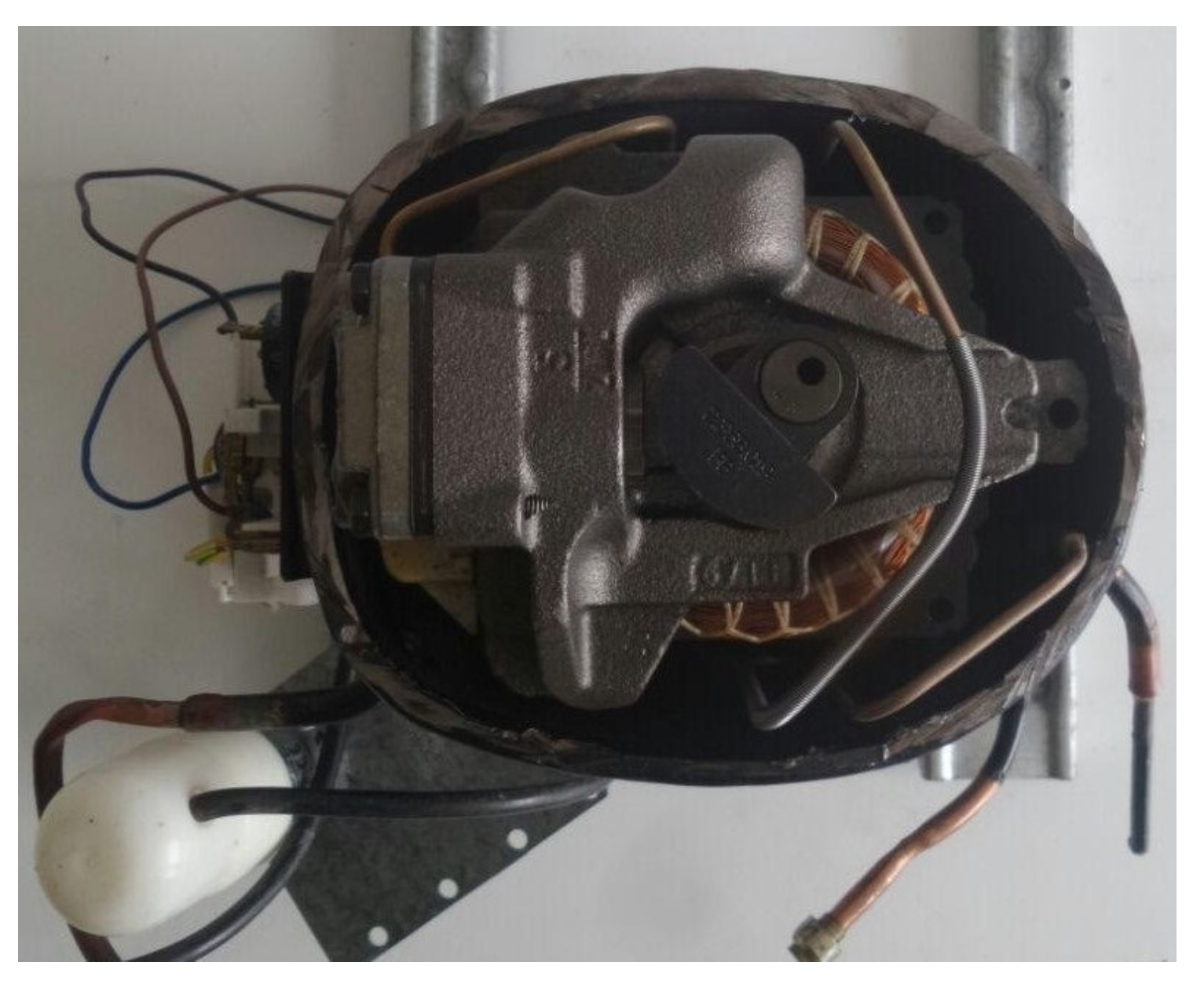
In this section, the practical implementation of the proposed system is investigated. The motor for which the converter is designed is a freezer motor. To analyze the current demanded by the motor, the internal motor circuit has been analyzed and measured. The photograph of the motor is shown in
Figure 10. The motor is an induction motor with he nominal voltage of the motor being 220–240 V DC, a nominal power of 100 W, and a frequency 50 Hz.
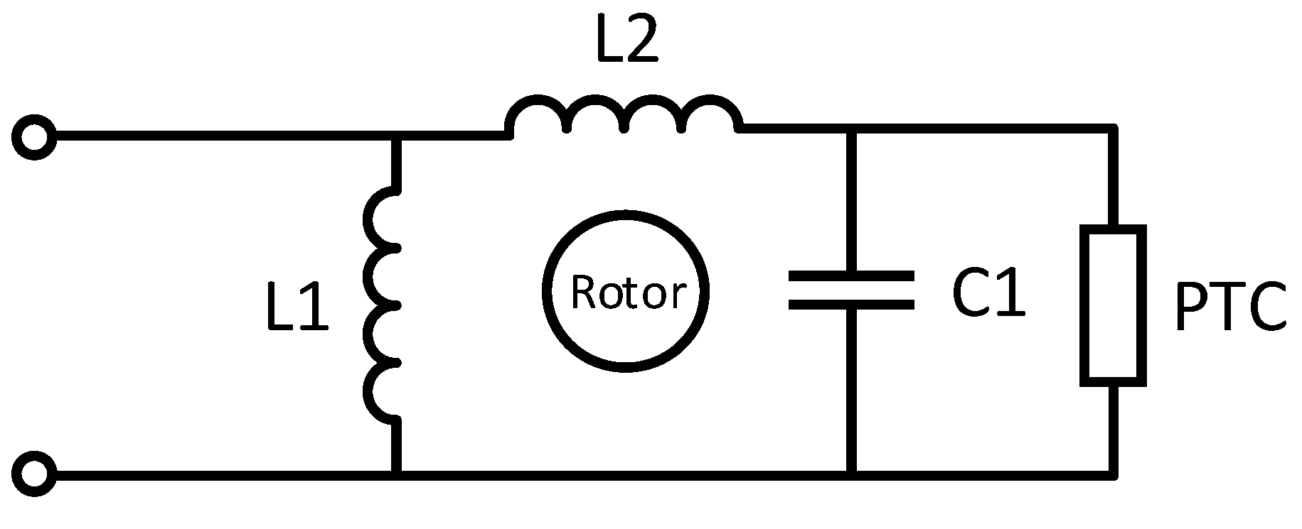
The freezer motor internal circuit scheme is shown in
Figure 11. The scheme in which it is based on, contains two inductances in parallel to a capacitor of 5
F and this circuit in parallel with a PTC thermistor, used as protection for the motor.
The measurements obtained to determine the impedances of the circuit depending on the frequency were carried out and the results are presented in
Table 4. Using the frequency at 500 Hz as the basis for nominal current, L1 and L2 take the values 105 and 349.1 mH, respectively, so the parallel inductance is 80.7 mH, assuming 70 mH due to internal motor factors. The negative value of the motor inductance is due to the reason that the winding gets capacitive.
For 230 V DC, a current of 3.3 A/ms is expected, so estimating a factor of at least ×3 for the peak current at start-up can be expected with an 11 A peak. These estimates are taken into account to evaluate the real current that the motor demands and to know that there is no internal problem in the electrical system. To control the boost converter, an LED driver constant current control integrated circuit (IC) was elected. That is a fast average current controller, which was programmable with constant off-time switching. It is a self-oscillating integrated circuit, and the frequency can be determined with the desired value. The IC is equipped with a current limit comparator for hiccup-mode output short circuit, and also, internal over-temperature protection was provided. The IC can operate with a variable input voltage range. It can be powered from a 15–450 V supply. The output current can be programmed by an internal 270 mV reference and a shunt. The timing resistor connected to the RT pin determines the off-time of the gate driver. Based on the datasheet, the off-time can be expressed as
A value of 470 k
for R
was chosen, therefore, the off-time of 19.1
s was obtained. According to the datasheet the inductor value can be calculated as Equation (
8). The inductor was designed with EE ferrite core transformers with an air gap.
When the voltage is applied to the Vin pin, it maintains a constant 7.5 V level at VDD. This voltage can also be used to power the IC and external circuitry connected to VDD. The VDD pin must be bypassed by a low ESR capacitor to provide a low impedance path for the high-frequency current of the gate driver. The IC employs a control scheme, achieving fast and very accurate control of average current in the buck inductor through sensing the switching current only. Hence, no compensation of the current-control loop was needed.
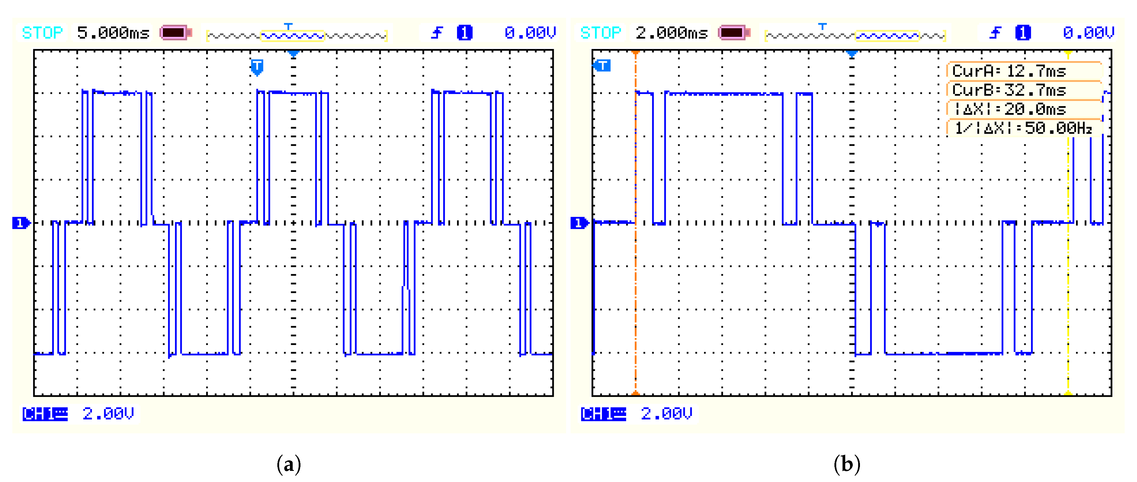
The practical results are extracted from an oscilloscope. Firstly, the output voltage of the inverter was measured at no load condition. The horizontal axis presents the time, and the vertical axis presents voltage. In
Figure 12a, the Inverter output voltage at no load is presented.
Figure 12b shows the inverter output voltage with one cycle to demonstrate the frequency of the signal in detail. As it can be noticed in the figure, the frequency of 50 Hz is achieved. The practical results were collected with an isolated oscilloscope probe with the scaling of ×50. Therefore, in the figure, the voltage scale shows 2 V per division, indicating 100 V per division, which means a peak voltage of 300 V. The time axis values for
Figure 12a,b are 5 and 2 ms, respectively.
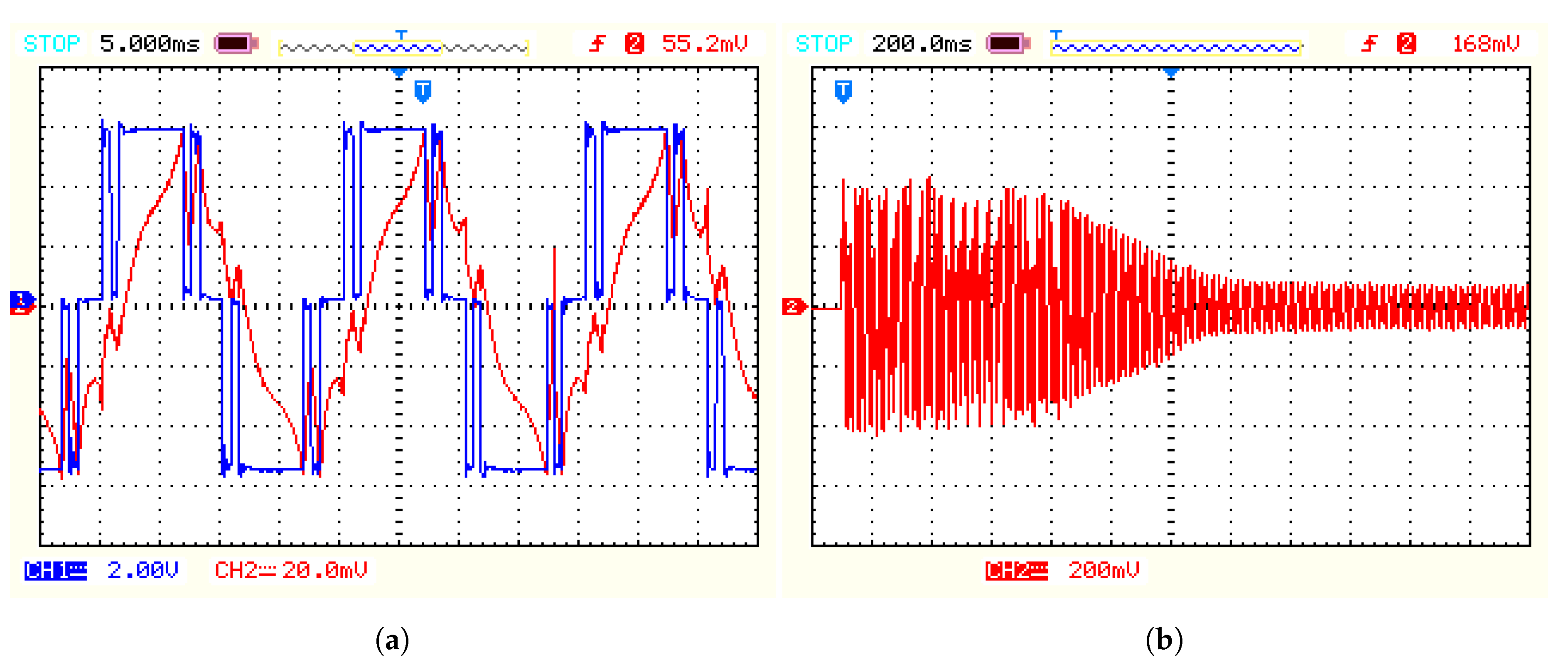
The motor voltage and current in steady state are shown in
Figure 13a. The blue waveform demonstrates the load voltage and the red waveform the load current. The load voltage is measured with the isolated probe of ×50 and the load current is measured with a normal probe. Firstly, the load current was measured through a current transformer with a scale of ×2.5, then the voltage across a shunt resistor with the vale of 0.1
was measured with the oscilloscope.
Figure 13a shows the motor current at start up. It can be noticed in the figure that at transient, the peak current of 10 A is realized. The Y axis presents the current, with 200 mV per division which determines 400 mv. The value is divided by a 0.1
resistor and multiplied by the scale of the current transformer which is results in 10 A.
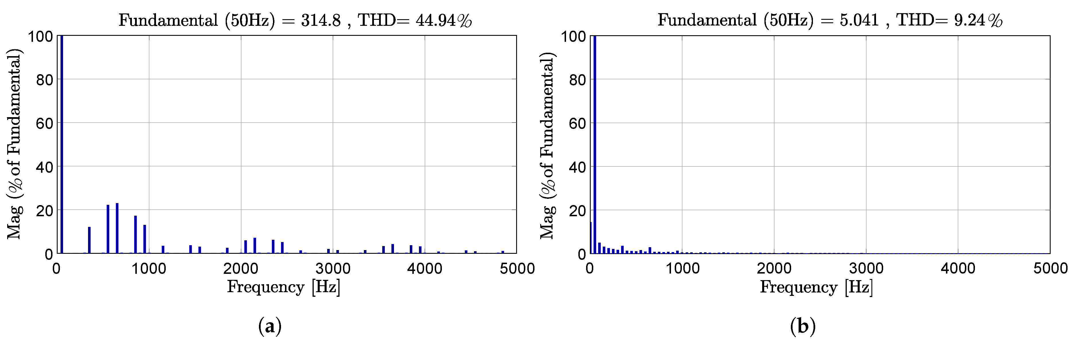
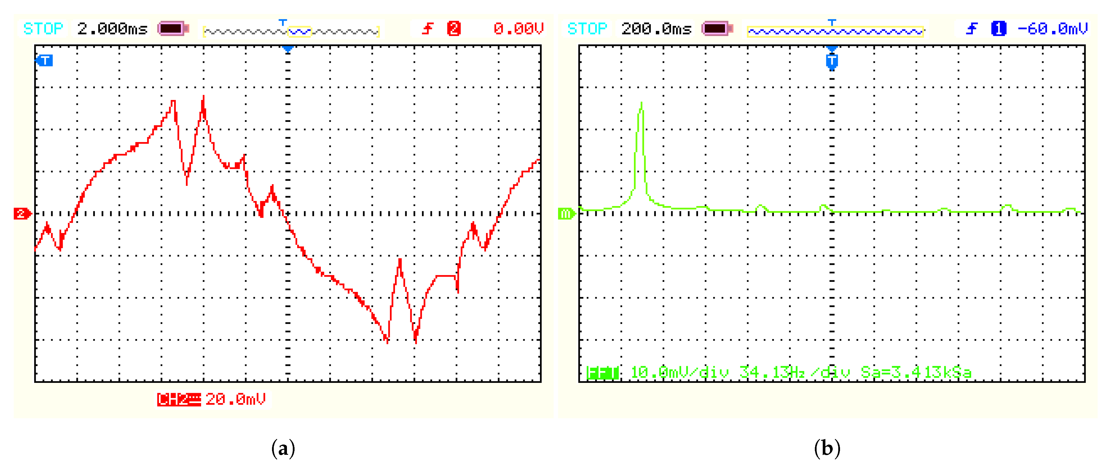
In
Figure 14a,b, the load current in steady state and THD of the load current are presented. Similarly, the load current can be calculated as before. The figure shows a scale of 20 mV per division, therefore, a peak current of 58 mV can be notified, which indicates a current of 1.45 A. It is recognized that the waveform demanded by the motor has a more sinusoidal shape. Some important reasons are due to the number of harmonics the system contains and also due to the type of scheme that the motor poses. As a conclusion, the choice of this type of generated pulse is valid to supply the motor, because the induction motor can operate with pulsated waveforms. The use of a modulated square waveform has the advantage of reducing the 5th and 7th harmonics of the voltage wave, having a lower Total Harmonic Distortion (THD) and, as a result, having a waveform with higher quality and less losses.
8. Conclusions
A single-phase photovoltaic (PV) inverter fed by a boost converter to supply a freezer motor with variable DC input is investigated in this paper. The PV panels can be stand-alone or grid-connected. A grid-connected PV is classified into two categories; with a transformer and without a transformer. A transformer type has galvanic isolation resulting in increased safety and provides no further DC current to the grid, however, it is expensive, heavy and bulky. The transformerless model has high efficiency and it is cheaper but it suffers from leakage of current between the PV and the grid. The proposed circuit was designed to be able to work on a PV panel array without batteries nor grid connection and has two stages. Firstly, the DC output of the PV panel that varies from 150 to 300 V will be applied to the boost converter. The boost converter will boost the input voltage to a fixed 300 V DC. Next, this voltage is supplied to the single-phase full-bridge inverter to obtain 230 V AC. In the end, The output of the inverter will feed a freezer motor. This paper proposes a stand-alone direct use of PV to supply a freezer; therefore, no grid connection will result in no leakage current between the PV and grid. The proposed circuit has some features such as no filtering circuit at the output of the inverter, no battery in the system, DC-link instead of AC link that reduces no-loads, has higher efficiency, and holds enough energy in the DC-link capacitor to get the motor started. The circuit uses no transformer, thus, it is cheaper and has a smaller size. Besides, the system does not require a complex PWM technique, because the motor can operate with a pulsed waveform. The control strategy uses a PWM signal with a desired timing. With this type of square wave, the harmonics (5th and 7th) of the voltage will be reduced, having a lower Total Harmonic Distortion and, as a result, having a waveform with higher quality and less losses. As the electricity direct from PV panels without storage nor grid connection is the cheapest source of energy today, it might stimulate renewable energy, while having negligible CO emissions and the potential to be cheaper at the same time. Experimental and simulation results were presented to prove the feasibility of the proposed strategy.
Author Contributions
Conceptualization, A.F.M. and A.V.d.B.; methodology, A.F.M.; software, A.F.M.; validation, A.F.M.; formal analysis, A.F.M.; investigation, A.F.M.; resources, A.F.M.; data curation, A.F.M.; writing–original draft preparation, A.F.M.; writing–review and editing, A.F.M.; visualization, A.F.M.; supervision, A.V.d.B. All authors have read and agreed to the published version of the manuscript.
Funding
This research received no external funding.
Conflicts of Interest
The authors declare no conflict of interest.
Abbreviations
The following abbreviations are used in this manuscript:
| AC | Alternating current |
| BOM | Bill of materials |
| BMS | Battery management system |
| CCM | Continues conduction mode |
| CO | Carbon dioxide |
| DC | Direct current |
| EFC | Ethanol-fueled fuel cell |
| ESR | Equivalent series resistance |
| IC | Integrated circuit |
| kWh | Kilowatt hour |
| PV | Photovoltaic |
| PID | Proportional integral derivative |
| PTC | Positive temperature coefficient |
| PWM | Pulse width modulation |
| SOC | State of charge |
| SPWM | Sinusoidal pulse width modulation |
| SVPWM | Space-vector pulse width modulation |
| SHEPWM | Selective harmonic elimination pulse width modulation |
| MOSFET | Metal–oxide–semiconductor field-effect transistor |
| MPP | maximum power point |
| MPPT | Maximum power point tracking |
| SMPS | Switched mode power supplies |
| THD | Total harmonic distortion |
| TL | Transformerless |
| VAT | Value-added tax |
References
- De Wild-Scholten, M.J.; Alsema, E.A.; Ter Horst, E.W.; Bächler, M.; Fthenakis, V.M. A cost and environmental impact comparison of grid-connected rooftop and ground-based PV systems. In Proceedings of the 21st European Photovoltaic Solar Energy Conference, Dresden, Germany, 4–8 September 2006; pp. 3167–3173. [Google Scholar]
- Kjaer, S.B.; Pedersen, J.K.; Blaabjerg, F. A review of single-phase grid-connected inverters for photovoltaic modules. IEEE Trans. Ind. Appl. 2005, 41, 1292–1306. [Google Scholar] [CrossRef]
- Calais, M.; Agelidis, V.G. Multilevel converters for single-phase grid connected photovoltaic systems—An overview. In Proceedings of the IEEE International Symposium on Industrial Electronics, ISIE’98 (Cat. No.98TH8357), Pretoria, South Africa, 7–10 July 1998; pp. 224–229. [Google Scholar]
- Jenkins, N. Photovoltaic systems for small-scale remote power supplies. Power Eng. J. 2014, 9, 89–96. [Google Scholar] [CrossRef]
- Deepa, R.; Nagashree, A.N.; Anand, K. Transformerless grid connected single phase inverter for power system application. In Proceedings of the 2015 International Conference on Emerging Research in Electronics, Computer Science and Technology (ICERECT), Mandya, India, 17–19 December 2015; pp. 418–422. [Google Scholar]
- Cui, W.; Yang, B.; Zhao, Y.; Li, W.; He, X. A novel single-phase transformerless grid-connected inverter. In Proceedings of the IECON 2011—37th Annual Conference of the IEEE Industrial Electronics Society, Melbourne, VIC, Australia, 7–10 November 2011; pp. 1126–1130. [Google Scholar]
- Das, J.C. Power System Harmonics and Passive Filter Designs; John Wiley & Sons: Hoboken, NJ, USA, 2015; ISBN 9781118887059. [Google Scholar] [CrossRef]
- Mwinyiwiwa, B.; Wolanski, Z.; Ooi, B.T. Microprocessor implemented SPWM for multiconverters with phase-shifted triangle carriers. In Proceedings of the IAS’97, Conference Record of the 1997 IEEE Industry Applications Conference Thirty-Second IAS Annual Meeting, New Orleans, LA, USA, 5–9 October 1997; pp. 542–1549. [Google Scholar]
- Tenconi, S.M.; Carpita, M.; Bacigalupo, C.; Cali, R. Multilevel voltage source converters for medium voltage adjustable speed drives. In Proceedings of the 1995 IEEE International Symposium on Industrial Electronics, Dubrovnik, Croatia, 10–14 July 1995; pp. 91–98. [Google Scholar]
- Carrara, G.; Casini, D.; Gardella, S.; Salutari, R. Optimal PWM for the control of multilevel voltage source inverter. In Proceedings of the 1993 Fifth European Conference on Power Electronics and Applications, Brighton, UK, 13–16 September 1993; pp. 255–259. [Google Scholar]
- IEEE Std 519-2014. IEEE Recommended Practice and Requirements for Harmonic Control in Electric Power Systems; IEEE: Piscataway, NJ, USA, 2014; pp. 1–29. [Google Scholar]
- Muljadi, E. PV water pumping with a peak-power tracker using a simple six-step square-wave inverter. IEEE Trans. Ind. Appl. 1997, 33, 714–721. [Google Scholar] [CrossRef]
- Mekhilef, S.; Rahim, N.A.; Omar, A.M. A new solar energy conversion scheme implemented using grid-tied single phase inverter. In Proceedings of the 2000 TENCON Proceedings, Intelligent Systems and Technologies for the New Millennium (Cat. No. 00CH37119), Kuala Lumpur, Malaysia, 24–27 September 2000; pp. 524–527. [Google Scholar]
- Vongmanee, V. The photovoltaic pumping system using a variable speed single phase induction motor drive controlled by field oriented principle. In Proceedings of the 2004 IEEE Asia-Pacific Conference on Circuits and Systems, Tainan, Taiwan, 6–9 December 2004; pp. 1185–1188. [Google Scholar]
- Duryea, S.; Islam, S.; Lawrance, W. A battery management system for stand alone photovoltaic energy systems. In Proceedings of the Conference Record of the 1999 IEEE Industry Applications Conference, Thirty-Forth IAS Annual Meeting (Cat. No. 99CH36370), Phoenix, AZ, USA, 3–7 October 1999; pp. 2649–2654. [Google Scholar]
- Shrestha, G.B.; Goel, L. A study on optimal sizing of stand-alone photovoltaic stations. IEEE Trans. Energy Convers. 1998, 13, 373–378. [Google Scholar] [CrossRef]
- Becherif, M.; Ayad, M.Y.; Hissel, D.; Mkahl, R. Design and sizing of a stand-alone recharging point for battery electrical vehicles using photovoltaic energy. In Proceedings of the 2011 IEEE Vehicle Power and Propulsion Conference, Chicago, IL, USA, 6–9 September 2011; pp. 1–6. [Google Scholar]
- Glavin, M.E.; Chan, P.K.; Armstrong, S.; Hurley, W.G. A stand-alone photovoltaic supercapacitor battery hybrid energy storage system. In Proceedings of the 2008 13th International Power Electronics and Motion Control Conference, Poznan, Poland, 1–3 September 2008; pp. 1688–1695. [Google Scholar]
- Wang, C.; Nehrir, M.H. Power management of a stand-alone wind/photovoltaic/fuel cell energy system. IEEE Trans. Energy Convers. 2008, 23, 957–967. [Google Scholar] [CrossRef]
- Salas, V.; Olias, E.; Barrado, A.; Lazaro, A. Review of the maximum power point tracking algorithms for stand-alone photovoltaic systems. Sol. Energy Mater. Sol. Cells 2006, 90, 1555–1578. [Google Scholar] [CrossRef]
- Salas, V.O.; Olias, E.; Lazaro, A.; Barrado, A. Evaluation of a new maximum power point tracker (MPPT) applied to the photovoltaic stand-alone systems. Sol. Energy Mater. Sol. Cells 2005, 87, 807–815. [Google Scholar] [CrossRef]
- Lazou, A.A.; Papatsoris, A.D. The economics of photovoltaic stand-alone residential households: A case study for various European and Mediterranean locations. Sol. Energy Mater. Sol. Cells 2000, 62, 411–427. [Google Scholar] [CrossRef]
- Ordóñez, J.; Jadraque, E.; Alegre, J.; Martínez, G. Analysis of the photovoltaic solar energy capacity of residential rooftops in Andalusia (Spain). Renew. Sustain. Energy Rev. 2010, 14, 2122–2130. [Google Scholar] [CrossRef]
- Zhang, Z.; Xie, Y.X.; Huang, W.P.; Le, J.Y.; Chen, L. A new SVPWM method for single-phase three-level NPC inverter and the control method of neutral point voltage balance. In Proceedings of the 2009 International Conference on Electrical Machines and Systems, Tokyo, Japan, 15–18 November 2009; pp. 1–4. [Google Scholar]
- Lee, S.J.; Lee, J.S.; Lee, K.B. Novel switching strategy for High-Efficiency of Single-Phase three-level inverters. In Proceedings of the 2014 IEEE Conference on Energy Conversion (CENCON), Johor Bahru, Malaysia, 13–14 October 2014; pp. 342–347. [Google Scholar]
- Zhetessov, A.; Ruderman, A. Time-domain optimization of current THD for a single-phase three-level inverter modulation. In Proceedings of the 2017 19th International Conference on Electrical Drives and Power Electronics (EDPE), Dubrovnik, Croatia, 4–6 October 2017; pp. 82–87. [Google Scholar]
- Rao, A.M.; Sivakumar, K. Five level single phase inverter scheme with fault tolerance for islanded photovoltaic applications. In Proceedings of the 2015 7th International Conference on Information Technology and Electrical Engineering (ICITEE), Chiang Mai, Thailand, 29–30 October 2015; pp. 194–199. [Google Scholar]
- Wang, C.; Zou, Y.; Jin, H.; Ding, K.; Zhang, Y. A high-performance five-level single-phase inverter using repetitive control and state feedback. In Proceedings of the IEEE International Conference on Electric Machines and Drives, San Antonio, TX, USA, 15–15 May 2005; pp. 846–849. [Google Scholar]
- Feloups, C.E.; Ali, A.I.; Mohamed, E.E. Design of single-phase seven-level inverter with reduced number of switching devices for PV applications. In Proceedings of the 2017 Nineteenth International Middle East Power Systems Conference (MEPCON), Cairo, Egypt, 19–21 December 2017; pp. 817–822. [Google Scholar]
- Chaniago, K.; Rahim, N.A.; Selvaraj, J. Novel fundamental-frequency-modulated modified H-bridge single-phase seven-level inverter for stand-alone photovoltaic system. In Proceedings of the 2011 IEEE Conference on Clean Energy and Technology (CET), Kuala Lumpur, Malaysia, 27–29 June 2011; pp. 225–230. [Google Scholar]
© 2020 by the authors. Licensee MDPI, Basel, Switzerland. This article is an open access article distributed under the terms and conditions of the Creative Commons Attribution (CC BY) license (http://creativecommons.org/licenses/by/4.0/).


