Article

Extended Spatial-Index LED Modulation for Optical MIMO-OFDM Wireless Communication

1
Electrical Engineering Department, Faculty of Engineering, King Khalid University, Abha 61411, Saudi Arabia
2
Electrical Engineering Department, Faculty of Engineering, Aswan University, Aswan 81528, Egypt
3
Electrical Engineering Department, Assiut University, Assiut 71515, Egypt
*
Author to whom correspondence should be addressed.
Electronics 2020, 9(1), 168; https://doi.org/10.3390/electronics9010168
Submission received: 28 October 2019 / Revised: 7 January 2020 / Accepted: 13 January 2020 / Published: 16 January 2020
(This article belongs to the Special Issue Visible Light (VLC) and Camera Communication)

Abstract

:
An efficient optical modulation technique for multi-input multi-output (MIMO) orthogonal frequency division multiplexing (OFDM) visible light communication system is proposed in this paper. The proposed modulation technique is termed as extended spatial-index light-emitting diode (LED) modulation. In the proposed technique, the indices (the spatial domain) of the LEDs are exploited in a dynamic style to not only get rid of the optical OFDM time-domain ( OFDM t d ) shaping problem but also to expand the LED indices spatial modulation domain. The indices of the active LEDs in the proposed technique are changed from the two LEDs active situation to the situation where all or several LEDs are active. Moreover, within the selected active LED indices, the power weight distribution and the positions of the OFDM components are varied to expand the resultant spatial domain. Therefore, the proposed technique offers a considerable spectral efficiency improvement over the up-to-date LED index OFDM modulation schemes even with a lower number of LEDs. The key idea of the proposed technique is to maximize the LEDs’ indices spatial position (spatial domain) utilization, where both the power weight allocation and the positions of the complex OFDM time domain components are varying several times over the same active LED indices combination, which improve the optical system spectral efficiency. The simulation results asserted the superiority of the proposed technique, as it improves both the average bit error rate (ABER) and the achievable data rate (R) compared with existing up-to-date OFDM-LED index modulations with even lower computational complexity.

Graphical Abstract

1. Introduction

The last decade has witnessed a phenomenal growth in wireless communications data. According to [1], mobile data traffic is expected to grow to 30.6 exabytes per month by 2020 (an eight-fold increase over 2015). To fulfill the ever-growing demand for such wireless data and with the aggravating limitations of the radio frequency (RF) spectrum, communication experts are rethinking visible light communication (VLC) as it is considered one of the optimal solutions for the indoor communications. Moreover, VLC attracts considerable interest in view of the fifth-generation (5G) wireless communication requirements.
With the state-of-art lighting light-emitting diode (LED) technology, VLC can also fulfill the low power requirement of the internet of things (IoT) PHY layer design [2]. Moreover, with the existing infrastructure in place for lighting in daily use and other distinct advantages such as large bandwidth (i.e., 30 GHz of open-license bandwidth), low cost, energy conservation, and secure communication [3,4,5], VLC is nominated as one of the most promising solutions for future wireless communication networks.
Consequently, there is an exponential growth in the deployment of the new optoelectronic technologies that can be utilized to efficiently exploit the enormous potential bandwidth of the optical wireless communications (OWC). Thus, OWC is expected to be indispensable for wireless data transmission, especially in short-range low-mobility indoor environments [6]. In OWC, data are transferred by modulating the LED light intensity. Hence, intensity modulation and direct detection (IM/DD) have emerged as one of the promising candidates for OWC systems [7,8].
In general, LED light intensity conveys information at the VLC systems’ transmitter side (TX) while the photo detectors (PDs) or cameras [9,10,11] are used at the receiver side (RX) to detect the transmitted information. Considering the nature of visible light, the OWC modulated signal has to be a positive real value (unipolar) signal. This requirement adds further constraints on OWC. Therefore, modulation schemes such as on-off keying (OOK), pulse width modulation (PWM), pulse position modulation (PPM), and unipolar M-ary pulse-amplitude modulation (M-PAM) can be used in a relatively straightforward fashion with the OWC [4]. Unfortunately, owing to their spectral and power inefficiency, none of the aforementioned modulation schemes could efficiently exploit the OWC system’s large bandwidth.
Therefore, researchers have recently turned their attention to integrate the high spectral efficiency OFDM with OWC systems. Despite its advantages, the OFDM signal must be represented as intensity in the OWC systems, thus its signal must be in real and positive form, while the equivalent base-band of the OFDM signals is generally complex and bipolar. Hence, many adjustments and modifications must be applied on the OFDM to cope with the optical wireless communications’ IM/DD requirements.
In [12], the DC biased optical OFDM (DCO-OFDM) was introduced where the unipolar signal was realized by adding a positive DC biased to the OFDM time-domain output from the inverse fast Fourier transform (IFFT). While the VLC-OFDM bandwidth efficiency gained strength by adding positive DC bias, unfortunately its optical power efficiency (OPE) was reduced significantly [13,14]. On the other hand, the asymmetrically clipped optical OFDM (ACO-OFDM) was presented in [15]. The ACO-OFDM enhanced the OPE of the optical wireless communication system at the expense of reducing its spectral efficiency (SE) and degradation of its bit error rate (BER), where its data rate was reduced to half of the conventional OFDM data rate. This dates back to the zero level clipping of the IFFT output signal and its output signals are restricted to be conveyed over the odd subcarrier only. The data error rate degradation problem of the ACO-OFDM has been handled in the unipolar-OFDM (U-OFDM) [14], where both positive and negative frames for the IFFT signal are individually transmitted. However, SE of the U-OFDM is still low (i.e., half of the conventional OFDM data rate).
Since multiple LEDs are basically installed in a single room to provide sufficient illumination, the MIMO-VLC system was introduced in [16,17,18]. The parallel utilization of multiple LEDs and PDs offers high data rates [19]. The utilization of different optical sources and receivers gives different spatially discrete optical wireless channels, and those various channels improve the system capacity and data rates.
Spatial multiplexing approaches were highlighted as a potential solution to enhance the channel capacity shortage of indoor OWC systems. Thus, different LEDs were utilized to transmit independent data streams over a short distance in [20]. Moreover, a multiplexing MIMO-LED system was considered in [21], where a zero-forcing (ZF) equalizer was used at its RX to mitigate the effect of channel interference. However, two assumptions were presumed in [21]. Firstly, the type of connection between the transmitters and receivers was assumed to be a direct line of sight (LOS). Secondly, the cross-talk is limited between the various sources since they assumed the spacing between sources up to 3 m. Moreover, a 4-channel MIMO system was depicted in [22], where the white light LEDs were utilized for data conveyance over a short distance in a diffuse environment. When the MIMO-OFDM system with four LEDs (channels) was demonstrated in [23], a data rate of 1 Gbit/s was achieved with an average bit error rate (ABER) of 10 3 over a distance of 1 m. In [24], the SE of the OWC system was enhanced by exploring different wavelengths in the visible light band.
Recently, spatial modulation (SM) [25,26,27,28] techniques were integrated with the optical MIMO-OFDM to improve the VLC system spectral and power efficiency [29,30,31,32,33], where the indices of transmit LEDs (spatial LEDs positions) were exploited to convey additional bits or to handle the complex OFDM time-domain shaping problem. For example, the need for a DC bias was eliminated in [30] by using 2 × 2 MIMO-LED SM. The OPE of the aforesaid system was significantly improved at the same SE, where the positive and negative OFDM time-domain signals transmitted at the same time over different LED indices. In [31], a four MIMO-LEDs were split into two different transmit groups to separately convey the real and the imaginary parts of the complex OFDM signal, and the scheme was teamed as MIMO-OFDM generalized LED index modulation (GLIM-OFDM). Based on each OFDM component sign information in the GLIM-OFDM, only one LED was activated in each group to convey the absolute value of that component over the VLC channel. In other words, two out of four LED indices would be inactive while the other two LEDs were exploited to convey the data. The GLIM-OFDM achieved a significant improvement in OPE and SE when it was compared to other optical OFDM systems [31]. Even so, there is a strict restriction on the number of LEDs at the GLIM TX. As it was reported in [32,33], the GLIM LED number must be 2 m where m is any integer ≥2. Therefore, in [32], a LED grouping scheme was proposed to handle the GLIM-OFDM aforesaid restriction, where the LED number became any even number 4 .
Nevertheless, both [31,32] still have a constraint on TX LED number ( n t ) without giving a clear link between their data rates (R) and n t . As far as we know, there were no systematic studies considering the aforesaid constraints in literature until the authors introduced the fully generalized index-spatial (FGIS) LED modulation in [33]. The FGIS relaxed the aforementioned LEDs number constraint and improved the optical communication system SE by providing an extra spatial domain (SD). Unfortunately, the complex OFDM signal signs barrier in FGIS minimized the effectiveness of the extra SD in improving the system SE. Moreover, it restricted the LED number to be greater than 3.
Here, a novel optical MIMO-OFDM communication modulation scheme termed as extended spatial-index light-emitting diode (ESI-LED) modulation is proposed. The key idea of the proposed ESI-LED is to maximize the LED’s indices spatial position (spatial domain) utilization, whereas the optical system SE of the ESI is improved by varying both the power weight allocation and the positions of the complex OFDM time domain components several times over the same active LED indices combination.
According to the aforesaid above concepts, the major contributions of this paper are as follows:
  • An efficient ESI-LED modulation scheme is proposed. In contrast to a GLIM-OFDM scheme, there is no barrier to utilize any number of LEDs in ESI-LED as long as n t 3 . Moreover, the attainable data rates of the ESI are semi-nonlinearly proportional to the number of LEDs deployed. The key idea of ESI-LED is to extend the resultant LED indices SD by maximizing the resulting LED combinations, whereas the same active LED indices are utilized many times with different power allocation values for OFDM real and imaginary components. Thus, the LED indices could be distinguished based on the real and imaginary part power allocation. Moreover, the number of active LEDs used for data transmission varies from the state in which only two transmit LEDs are activated to the state in which multiple/all transmit LEDs are activated. This will improve the utilization of the resultant spatial domain, thus the overall system spectral efficiency will be improved.
  • A low complexity maximum a posteriori probability (MAP) estimator is proposed on the ESI receiver side. The MAP estimator in [31] is reformulated to be compatible with ESI-LED, where multiple LEDs or all LED indices are active simultaneously with different OFDM real part power allocations to convey OFDM time domain components.
  • A general computational complexity (CC) form for both the proposed ESI and the GLIM are derived and tested in the simulation result section. Unlike the GLIM complexity analysis given in [31], the given CC analysis is derived to support any n t × n r MIMO-LED configurations with/without spatial modulation.
The rest of this paper is structured as follows: In Section 2, the system model for the proposed ESI-LED scheme is presented as well as the indoor optical wireless channel model. The simulation results with different scenarios with the receiver CC are introduced in Section 3. Finally, the paper is concluded in Section 4.

2. System Model

In this section, the proposed ESI-LED system structure and its maximum a posteriori probability (MAP) estimator are presented as well as the indoor optical wireless channel model.

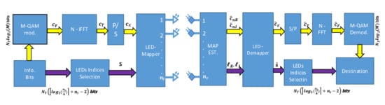
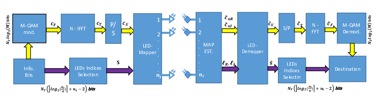
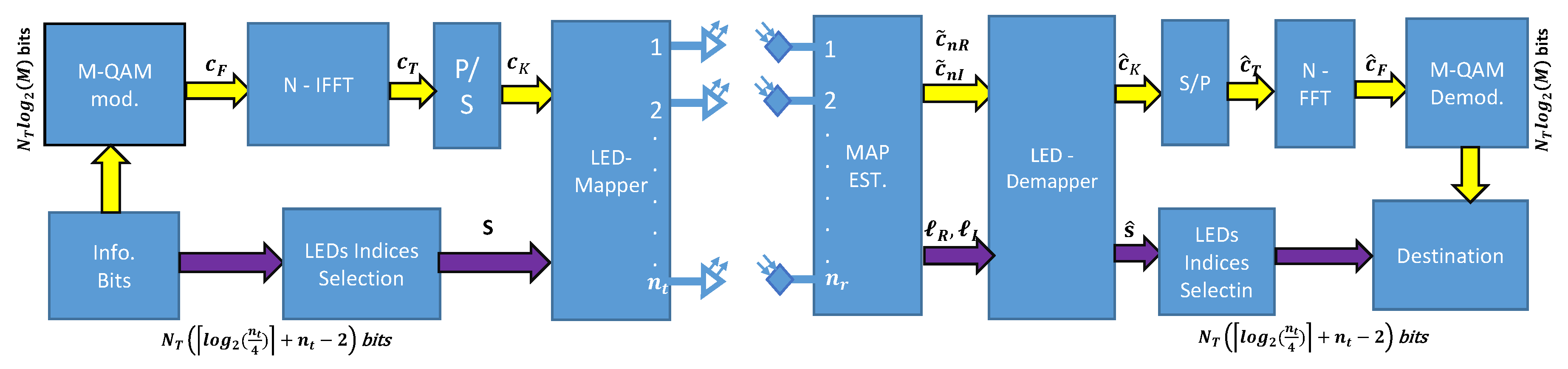
2.1. The Proposed ESI-LED System

An illustration of the proposed ESI-LED system structure is shown in Figure 1, where the incoming data bits are split into two separated groups. The first group is formed from N T l o g 2 ( M ) bits (data bits), where N T is the OFDM sub-carrier number and M refers to the modulation order. As shown in Figure 1, the OFDM time domain ( OFDM t d ) vector c T is generated by applying IFFT on the resultant modulated vector c F . The next group of bits consists of N T l o g 2 ( n t 4 ) + n t 2 , which are defined as spatial bits (p), where n t is the number of transmit LEDs and . is the ceiling operator. The OFDM time domain vector c K is conveyed by LED indices that are selected based on both p and the OFDM signal signs information. The LED indices in the proposed ESI-LED are varied from the situation where just two LEDs are activated to the situation where many or all LEDs are activated. The proposed system represents a combination of the traditional fully generalized SM [26,27,28] and the optical SM systems which are depending on a fixed number of active LEDs (only two active LEDs). The reliability of the proposed ESI communication channel will be increased by varying the number of transmit LEDs [26,27,28].
In the ESI, all prospective LED indices combinations C are exploited to improve the utilization of the resultant SD. Moreover, to increase the effectiveness of the resultant SD in improving the proposed system SE, the power allocations of the OFDM real part component ( c n R ) are also varied q i times over the same active LED indices C i , where q i is equal to the number of the active LEDs in the LEDs combination C i (i.e., q i = n t i when n t i 3 and q i = 1 when n t i = 2 ). Hence, there will be i q i C i available joint LED indices and power allocations combinations. The resultant combinations are split into various G groups, and every group involves four unparalleled combinations to include all four potential likelihoods for OFDM t d signs information (i.e., ± c n R ± j c n I ). Thus, the resultant p from the proposed ESI can be given by l o g 2 ( i q i C i / 4 ) (group selection bits), where . denotes the floor process. The extended SM over the joint LED power allocations combinations grouping is proposed in the ESI model, which differs from the traditional SM schemes that utilize the spatial modulation domain over the LED indices only. This would reinforce the SE of the ESI modulation technique. In this context, the maximum achievable data rate of the ESI ( R E S I ) could be given as:
R E S I = l o g 2 ( M ) + l o g 2 i q i C i 4 ,
R E S I = l o g 2 ( M ) + l o g 2 [ n t 2 + q = 3 n t q n t q / 4 ,
R E S I = l o g 2 M data bits n t = 3 , l o g 2 M data bits + l o g 2 n t 4 + n t 2 spatial bits n t > 3 ,
where . . is the binomial operator.
Table 1 shows an example for the ESI-LED transmission functionality, where an extra one and two bits per channel use (bpcu) are gained by the ESI-LED system over the FGIS [33] and the GLIM-OFDM [31], respectively, when n t = 4 . Essentially, the proposed ESI-LED scheme achieves SE equal to R E S I = l o g 2 ( M ) + 2 bpcu using only four transmit LEDs. In the example, 16 transmitted LEDs are required with the GLIM-OFDM [31] to achieve the same SE under the assumption that there are two spatial bits provided by the GLIM-OFDM [33], while five transmitted LEDs are needed with the FGIS ( R F G I S = l o g 2 ( M ) + n t 3 ) [33] to achieve the same SE.
Back to our example as shown in Figure 1, the data are split into two groups; the OFDM frame data ( N T l o g 2 ( M ) ) and the extended p ( N T ( l o g 2 n t 4 + n t 2 ) ) and it is equal to 2 N T in this example.
For example, if the upcoming OFDM time domain signal is c n = c n R j c n I and the group section are p = { 1 0 } n , then, as seen in Table 1, the p = { 1 0 } n will be used to map c n to the 3rd group. Moreover, based on the c n signs information, the absolute value of the real part ( c n R ) will be transmitted over T X L E D 1 and T X L E D 2 , while the positive unipolar imaginary part c n I will be conveyed over T X L E D 4 .
Another example is shown in Table 2, where four addition bits ( p = 4 b p c u ) are gained by the proposed ESI by using only five transmitted LEDs. However, under the assumption of using the same modulation order to achieve the same SE, 7 and 64 transmitted LEDs are needed with FGIS [33] and the GLIM-OFDM [31], respectively.
For example, if the upcoming OFDM complex time domain (OFDM t d ) signal is c n = c n R + j c n I , and the spatial bits are p = { 1 1 0 1 } n , then, as seen in Table 2, the 14th group will be selected. Moreover, the signs of real and imaginary of c n will determine which of the LEDs will become active in the aforesaid selected group. Thus, the 3rd row of the pre-selected 14th group will be selected to convey the data, where the unipolar c n R will be transmitted over T X L E D 1 , T X L E D 3 and T X L E D 5 , while the unipolar imaginary part c n I will be transmitted over T X L E D 4 . Finally, the transmission vector of the proposed ESI will be equal to u = c n R / 3 0 c n R / 3 c n I c n R / 3 T , where u R + n t × 1 ; R + n t × 1 is the indicator for the positive real subspace.

2.2. The Maximum a Posteriori Estimator

In general, the transmitted vector u is conveyed over optical wireless channel H R + n r × n t and is effected by an additive white Gaussian noise (AWGN) v R n r × 1 , where v N ( 0 , σ n 2 ) , and n r is the receiver PD number. The optical MIMO channel can be written as
H = h 1 , 1 h 1 , n t : : h n r , 1 h n r , n t ,
where h n r , n t represents the channel gain of the optical wireless link between the LEDs ( n t ) and PDs ( n r ) .
Thus, the expression of the received signal y R n r × 1 in the proposed ESI-LED can be expressed as:
y = H u + v ,
y = h i R c n R + h i I c n I + v ,
where h i R and h i I are the aggregation of active optical wireless channel columns required for transmission the unipolar values of the real and imaginary components of the complex OFDM t d , respectively, and, for l t h combination C l { C 1 , C 2 , , C l , , C 2 p + 2 } , they are given by:
h i R = j C l N i R h j , h i I = h k , k C l , k j ,
where N i R = 1 , 2 , , n t 1 is the number of active LEDs for the real part, and h i j is the active channel column for imaginary parts (only one active LED).
In general, the electrical received signal to noise ratio ( S N R R X ) [34] is expressed by:
S N R R X = P R X e l e c σ n 2 = 1 σ n 2 ζ 1 n r m = 1 n r n = 1 n t h m , n I 2 ,
where ζ is the electrical-to-optical conversion coefficient, and it was assumed to be unity [31,33], P R X e l e c is the average received electrical power, and I ca represents the mean emitted optical intensity.
By normalizing the M-QAM constellation to have unity power, and at a high value of OFDM subcarriers N T , with the assumption that the power of the OFDM real part is equally divided between the active LEDs, then non-zero elements of the vector u will follow clipped Gaussian distribution. Accordingly, the average electrical power emitted from the active LEDs [31,33] for either c n R or c n I is given by:
I = E { c n R ( I ) ± } = 0 υ P c n R ( I ) ± ( υ ) d υ = 0 υ ( 1 π e υ 2 u ( υ ) + 1 2 δ ( υ ) ) d υ = 1 2 π ,
where u ( υ ) and δ ( υ ) be the unit step and Dirac delta function, respectively.
Full knowledge of the optical channel state information ( C S I ) at the system receiver is presumed [31,32,33]. Thus, for a certain joint power allocation and LED indices (i.e., the LED indices for both the real part i R , and for the imaginary part i I ), the conditional maximum a posteriori ( M A P ) estimation for the values c ^ n R and c ^ n I [31,33] can be written as follows:
c ^ n R i R , i I , c ^ n I i R , i I = a r g m a x c ˜ n R , c ˜ n I P c ˜ n R , c ˜ n I / y ,
where P c ˜ n R , c ˜ n I / y is the conditional probability density function ( p . d . f . ) of c ˜ n R and c ˜ n I when y is known.
By considering the independence between c ˜ n R , and c ˜ n I , (10) and by utilizing the Bayes’ rule, Equation (10) can be rewritten as follows:
c ^ n R i R , i I , c ^ n I i R , i I = a r g m a x c ˜ n R , c ˜ n I P y / c ˜ n R , c ˜ n I P c ˜ n R P c ˜ n I .
Since P y / c ˜ n R , c ˜ n I N ( h i R c ˜ n R + h i I c ˜ n I , v ) (note that the constants in (11) are ignored since they are not effected on the estimation process),
c ^ n R i R , i I , c ^ n I i R , i I = a r g m a x c ˜ n R , c ˜ n I e c ˜ n R 2 + c ˜ n I 2 × e y h i R c ˜ n R h i I c ˜ n I 2 / 2 σ n 2 .
After taking the logarithm of Equation (12),
c ^ n R i R , i I , c ^ n I i R , i I = a r g m i n c ˜ n R , c ˜ n I M M A P i R , i I , c ˜ n R , c ˜ n I ,
where M M A P . is the MAP estimation metric and it is given by:
M M A P = y h i R c ˜ n R h i I c ˜ n I 2 + 2 σ n 2 c ˜ n R 2 + c ˜ n I 2 .
By using the same analysis as in [31,33], Equation (14) can be written as
M M A P = A c ˜ n R 2 + B c ˜ n I 2 + C c ˜ n R + D c ˜ n I + E c ˜ n R c ˜ n I ,
where
A = j C l h j T h j + 2 σ n 2 , B = h k T h k + 2 σ n 2 , C = 2 y T + j C l h j , D = 2 y T + h k , E = 2 j C l h j T h k , k C l , k j .
To solve (13), the first order derivative of (15) with respect to c ˜ n R , and c ˜ n I is equating to zero, then the solution can be written as
c ˜ n R i R , i I = 2 B C E D E 2 4 A B + , c ˜ n I i R , i I = 2 A D E C E 2 4 A B + ,
where a + = max ( 0 , a ) .
It is worth mentioning here that, due to the transmitted signals of the proposed ESI, the FGIS [33], and the GLIM-OFDM [31] have the same distributions (i.e., clipped Gaussian probability density function), therefore the above M A P derived analysis is almost the same as the M A P derived analysis given in [31,33]. However, there is a major difference between the proposed ESI-LED and both FGIS [33] and the GLIM-OFDM [31] in the cardinality size of the spatial domain (group selection bits). In the proposed ESI-LED, the power allocation of the OFDM real part competent is exploited (varied) along with the active LED indices to improve the utilization of LED spatial domain.
To determine the active channel (LEDs) for both the real component i R and the imaginary component i I as well as the estimated c ˜ n R and c ˜ n I , all the output (results) from (17) are found for all prospective joint power allocations i R and i I combinations (see Table 1 and Table 2, for example) as explained in Algorithm 1. In the algorithm, the number of expected LED combinations is equal to 2 p + 2 .
Algorithm 1 Estimating the values of c ˜ n R , and c ˜ n I for each expected joint power allocations LEDs indices.
Inputs : All the expected LED indices i R and i I , the received vector y , and H.
Procedures : For each expected LED indices:
1:
Find the values of A , B , C , D , and E by applying (16).
2:
Find all the positive values for c ˜ n R , and c ˜ n I by applying (17).
3:
Store the c ˜ n R , and c ˜ n I with their corresponding joint power allocations LED indices.
4:
Repeat steps 1, 2, and 3 for each expected joint power allocations LED indices.

Outputs : All possible estimated values for c ˜ n R , and c ˜ n I with their corresponding LED indices i ˜ R and i ˜ I .
Finally, the actual estimation of c ˜ n R , c ˜ n I , i ˜ R , and i ˜ I can be found by
c ˜ n R , c ˜ n I , i ˜ R , i ˜ I = a r g m i n i R , i I M M A P i R , i I , c ˜ n R i R , i I , c ˜ n I i R , i I .
Having obtained these estimates, the transmitted p are estimated by locating the group G in which the joint power allocation i ˜ R , and i ˜ I are located. Finally, the OFDM signs information are estimated based on power allocation i ˜ R , and i ˜ I .

2.3. Indoor Optical Wireless Channel Model

In a typical VLC system, the optical signals emitted from the LEDs are conveyed over an optical MIMO channel. Because of some negative attributes of the VLC channels (i.e., reflection, diffusion, interference, movement, and noise), the channel causes loss, fading, and distortion of the transmitted signal [35]. This loss must be as small as possible since it affects the transmission rate directly. Therefore, it is important to understand the response of different VLC channels well. Evaluating the channel impulse response (CIR) of the VLC systems is a difficult job as its received power is associated with the optical channel parameters [31].
Since the visible light signal at any point consists of a line of sight (LOS) signal as well as a contribution from number of reflections by walls or objects in the room (i.e., Non-LOS), to evaluate the total gain of indoor VLC channel, the VLC channel model in [36] was exploited in [31,32] as it is focused on the limited number of reflections (i.e., up to 2nd order).
In general, the channel gains of optical link between certain LED and the PD can be expressed as [28,31]
h r , t = ( m + 1 ) A r R p 2 π d r , t 2 c o s m ( ϕ r , t ) c o s ( ψ r , t ) , 0 ψ r , t Ψ 1 / 2 ,
where m = l n ( 2 ) / l n ( c o s ( Φ 1 / 2 ) ) is the order of Lambertian emission expressing directivity of the source beam, Φ 1 / 2 is the semi-angle of the LED, A r is the PD area, R p is the responsivity of PD and it always takes as unity, ϕ r , t , ψ r , t are the angles of irradiance and incidence, respectively, d r , t is the distance between the LED t , and the PD r and Ψ 1 / 2 is the semi-angle of PD (i.e., field of view (FOV)).
Moreover, the LED maximum transmitted optical power can be expressed as
P t = lim 0 1 2 T T T X ( t ) d t ,
where X ( t ) is the instantaneous transmitted optical power.
Thus, the average received optical power P r at the PDs can be estimated by
P r = h r , t P t .
The channel model (19) was limited to the assumption of a Lambertian source and did not consider the effect of reflections. Thus, the physical channel modeling approach in [37] has been introduced, whereas the VLC channels were modeled based on the ray-tracing based approaches that take into account precisely effects of propagation environment, light sources, and detectors (i.e., objects, FOV, etc.).
However, the same setup configurations that were used in [31] are considered in this paper, where a 4 × 4 MIMO-VLC scheme was used for ease of demonstration as shown in Figure 2. The physical VLC channel parameters of the simulation environment are summarized in Table 3, which contains the coordinates of the luminaries and PDs for three different configurations as shown in Figure 2. In configuration (config) A, the PDs are located in the center of the table with 0.1 m distance between each, while, in configuration B, the PDs are located in the corner of the table with 0.8 m distance between each. Both luminaries and PDs are assumed in a vertical position in aforesaid configurations; in contrast, in configuration C, the PDs are located in the center of the table with distance 0.1 m between each other, but rotated by 45 in the x y -plane and titled by 60 in the y z -plane, where it can increase the LOS link strength. These parameters are used to obtain the CIR between each transmitter and receiver.

3. Simulation Results and Computational Complexity

In the following, the ESI-LED efficiency is evaluated and compared with the FGIS [33] and the GLIM [31] performances. Here, we used the same simulation parameters used with the GLIM-OFDM systems [31,33]. Moreover, as a fair comparison, the GLIM-OFDM system architecture is adapted to support the operation of the spatial modulation along with its conventional functions.
The conventional GLIM-OFDM was first introduced in [31] to support simultaneous transmission of the complex time-domain OFDM signal (i.e., ± c n R ± j c n I ) over the optical channel, whereas four LEDs were used (two LEDs for the real part ± c n R and the other two for the imaginary part ± j c n I ) to convey both the values and the signs information of the complex OFDM signal. However, this adds restrictions on the LED number of the GLIM-OFDM transmitter side (i.e., LED number must be equal 2 i , i = 2 , 3 , 4 , ). Then, in [32], a new LED grouping technique was introduced to relax the GLIM LED number problem to be equal to i 4 and i is an even number.
Therefore, to make the GLIM-OFDM support the SM along with its normal functionality, the GLIM-OFDM structure/functionality is adapted (without major changes in its architecture) as follows.
All possible LED indices on the TX side of the GLIM-OFDM ( n t ) are split into distinct sets with each set involving four unparalleled combinations to include all four potential likelihoods for OFDM t d signs information (i.e., ± c n R ± j c n I ). Thus, a S = l o g 2 ( n t / 4 ) extra bits (group selection) will be produced, and the new rate of the GLIM-OFDM in the above case can be given by
R G L I M = l o g 2 ( M ) + l o g 2 n t 4 .

3.1. Achievable Data Rate (R)

The achievable data rate ( R ) of the proposed ESI-LED modulation scheme (3) under the assumption of very high SNR values is evaluated and compared with both the GLIM [31] and FGIS [33] rates at different n t . Here, a modulation of 4-QAM is presumed to be applied on this test. As Figure 3 illustrates, the GLIM can not work when the number of transmit LEDs below four, since it does not have a sufficient number of unique LED indices to include all four potential likelihoods for OFDM t d signs information, while the proposed ESI and the FGIS [33] are working with only three LEDs. Moreover, Figure 3 shows that the proposed ESI scheme achieves a semi-nonlinear incremental relationship in its R with respect to the n t , while the FGIS achieves linear increment. Hence, for n t = 9 , ESI gains SE of 11 bpcu, while GLIM and FGIS attain only 4 and 8 (i.e., l o g 2 ( M ) + n t 3 [33]) bpcu, respectively. Therefore, the proposed ESI can provide a higher SE value compared to the inferior SE value provided by the GLIM or FGIS.

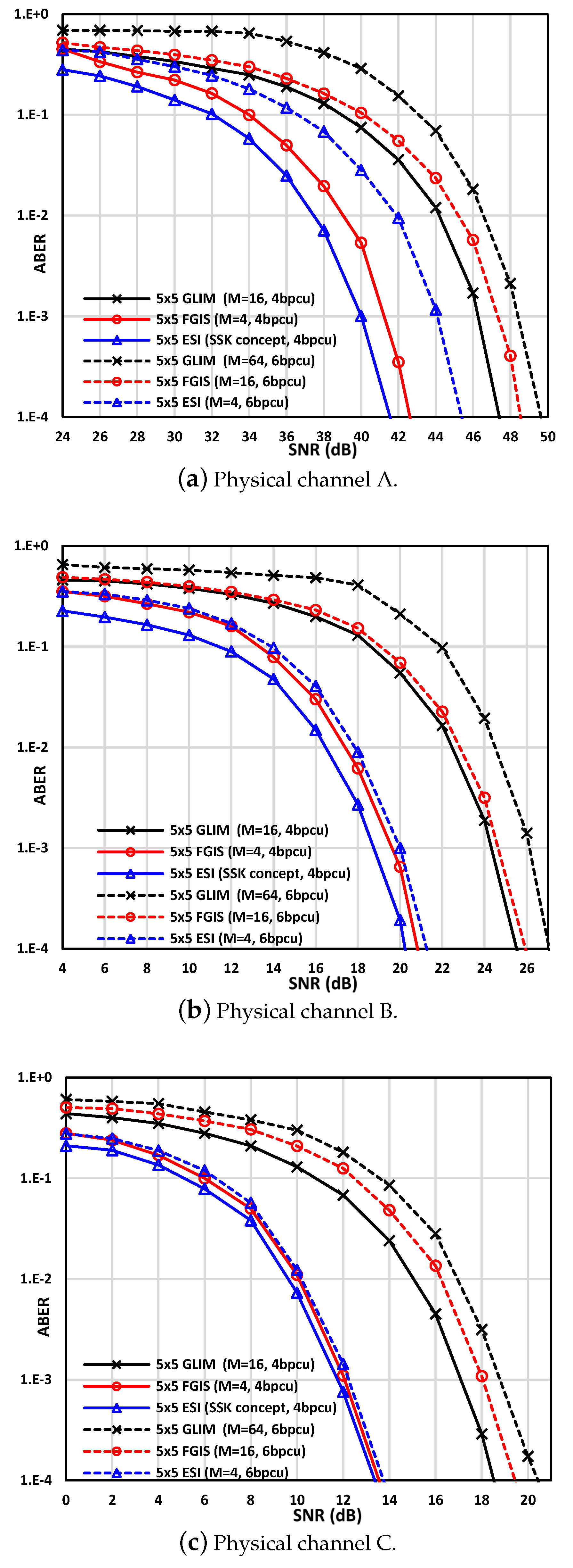
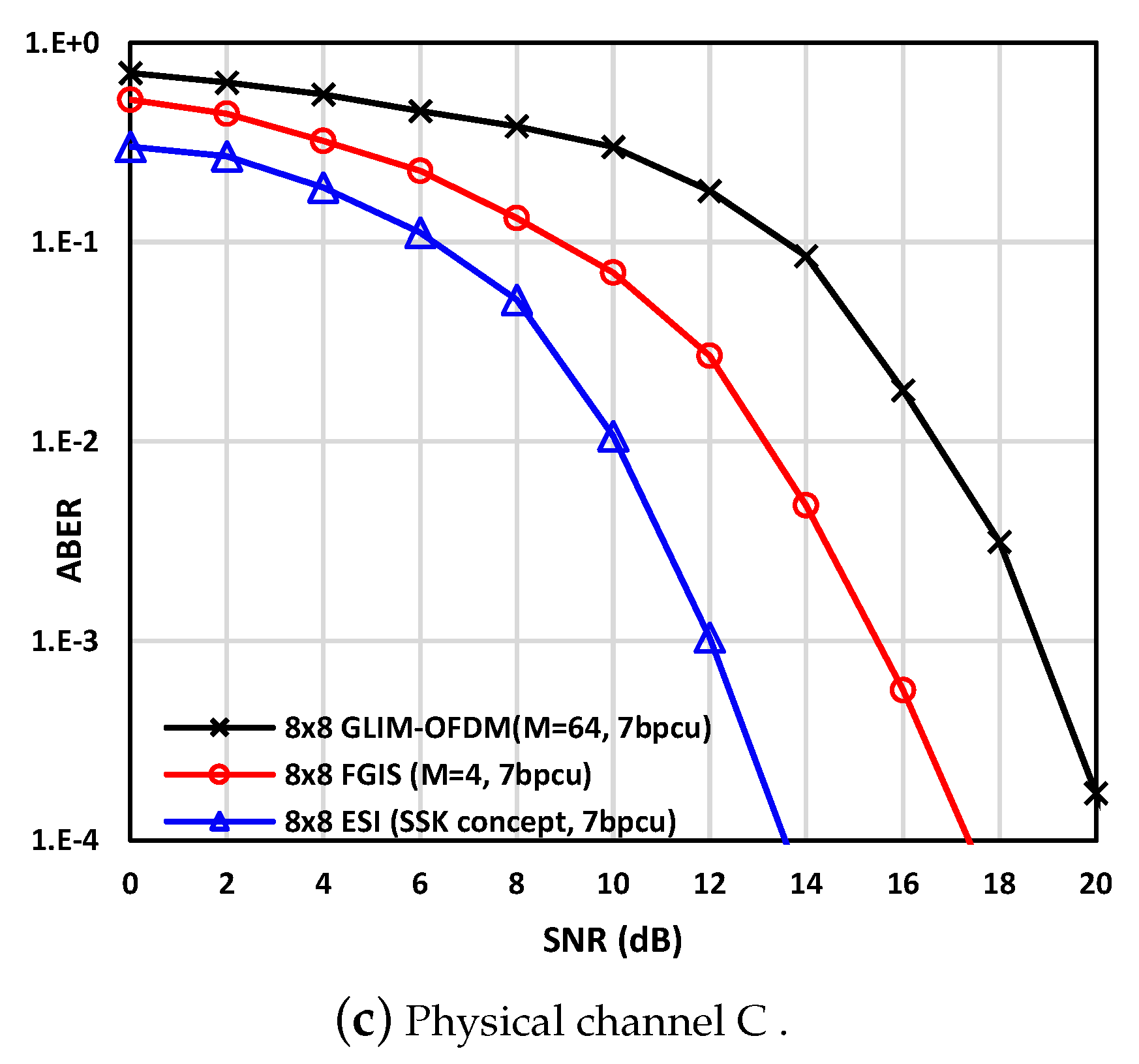
3.2. Average Bit Error Rate (ABER) Performance

In this subsection, the average bit error rate (ABER) of the proposed ESI is examined and compared with both the GLIM [31] and the FGIS [33]. Herein, the same simulation parameters and the same three physical channels that were used in [31,33] are used, whereas the parameters (channel matrices) of the three physical channels were estimated based on the geometric configuration of LEDs and PD locations shown in Figure 2. Actually, in our simulations, we followed the same configuration setup given in [31,32,33]. Thus, the proposed ESI modulation scheme is tested and compared to the GLIM system [31,32], under the same configuration setup (i.e., Figure 2) with the same three channels given in [31,32], whereas the three channel models are estimated from this configuration setup and they are named physical channels A, B, and C. In general, the resultant three indoor VLC channels can be classified into three categories: first, the weakest correlation H A P that is far from being a diagonal matrix; second, the modest correlation H B P ; third, H C P that is considered to have the strongest diagonal structure (weak correlated channels) [31]. In other words, the configuration setup was chosen to cover many of the channel correlation cases (high, medium, and low correlation) as it was reported in [31], which was refracted on proposed ESI and the GLIM performances. The complete information about the aforementioned configuration setup is given in [31]. Although the distance between PDs seems to not be practical for some applications (i.e., d P D s = 0.1 m), but with the state-of-the-art current and future micro/nano electronics LED/PD technologies [38,39], the distance between PDs could be shrunk to be practical (with a little effect on the channel correction).
However, two various scenarios with several MIMO-LED configuration are presumed. In the first scenario, the same order of modulation (M) is presumed to be utilized with the ESI, GLIM, and FGIS, whilst various MIMO-LED number (configuration) are utilized to fulfill the same SE. In the second scenario, the proposed ESI, GLIM, and FGIS are presumed to apply the same transmit MIMO-LED configuration, whilst various M are used to fulfill the same SE.
Scenario 1: The same modulation order with different MIMO-LED configuration.
In this scenario, the proposed ESI and the GLIM systems are tested with their row version i.e., the ESI is tested with 3 × 3 LED configuration without any spatial data and the GLIM is tested with 4 × 4 LED configuration. In both systems, modulation orders of M = 4 , M = 8 , and M = 16 are used to fulfill a spectral efficiency of 2, 3, and 4 bpcu, respectively. Since it was reported in [33] that the 3 × 3 FGIS captured the same ABER performance of the 4 × 4 GLIM, the ABER performances of the proposed ESI and the GLIM are considered only in this scenario.
Figure 4a–c show the ABER of the both ESI and the GLIM for the physical channels, A, B, and C [31,33]. With each channel, 2, 3, and 4 bpcu, SEs are examined using the aforementioned MIMO-LED configurations. As it can be noticed from Figure 4, the SNR that needed to achieve the same ABER for the channels A, B, and C is varied, this owing to the correlation nature of the three channels, whereas channel A is the most correlated channel and channel B is the modest correlated one, while channel C is the most diagonal channel (less correlated). To achieve the aforementioned SEs, MIMO-LEDs of 4 × 4 are needed with the GLIM while only 3 × 3 are used with ESI. Despite this, the results show that the proposed ESI captures almost the same ABER performances GLIM as shown in Figure 4.
Note that the three 3 × 3 MIMO physical channels that are used with the proposed ESI are just 3 × 3 sub-matrices of three 4 × 4 physical channels A, B, and C given in [31,33], and each 3 × 3 sub-matrix is chosen randomly from its corresponding 4 × 4 channel matrix.
Scenario 2: The same MIMO-LED configuration with different modulation orders to achieve the same SE.
In this scenario, two different tests are conducted, where the first test MIMO-LED configuration of 5 × 5 is used with the proposed ESI, the GLIM, and the FGIS systems, to achieve SE of 4 and 6 bpcu. Likewise, the same three physical channels A, B, and C are used in this scenario as shown in Figure 5a–c, respectively. However, a modulation order of M = 16 and M = 4 is exploited with the GLIM and the FGIS system, respectively, to fulfill an SE of 4 bpcu, while the ESI needs no modulation to fulfill the same SE. The SD was only exploited in the proposed ESI to convey data. In other words, the space shift keying (SSK) modulation concept [40] is used, whereas a predefined fixed dummy signal δ was transmitted on the active LED indices as a label to distinguish between the active and non-active LED indices. Therefore, a simple maximum likelihood estimator (MLE) is used with the proposed ESI in this scenario instead of the MAP (10). However, the MLE with the fixed dummy signal δ is given by
δ ˜ = a r g m i n δ y δ i = 1 N δ h l i 2 ,
where δ is the active LED indices and N δ = 1 , , n t 2 .
Note that the 5 × 5 LEDs configuration in GLIM [31] is the same as 4 × 4 , as only four out of five LEDs are used and the 5th LED will be idle [31,32]. On average, for the SE of 4 bpcu, the proposed ESI introduced 4.5, 5.1, and 4.5 dB saving compared to the GLIM, while it introduced 1, 0.75, and 0.45 dB saving compared to the FGIS as shown in Figure 5a–c, respectively. To achieve an SE of 6 bpcu in the same test (i.e., with LED configuration of 5 × 5 ), a modulation order of M = 64 and M = 16 are used with the GLIM and the FGIS, respectively, while a modulation order of M = 4 is used with the proposed ESI to fulfill the same SE ( l o g 2 ( M ) + 4 ). However, the simulation results furtherly manifest the superiority of the proposed ESI compared to the GLIM and the FGIS systems as it provides about 4.5 dB average saving compared to the GLIM while it introduced 3.75 dB average saving compared to the FGIS as shown in Figure 5.
In the second test in this scenario, 8 × 8 LEDs configuration is applied on the proposed ESI, the conventional GLIM system, and the FGIS system to achieve an SE of 7 bpcu. Therefore, a modulation order of M = 64 QAM is used with the GLIM to satisfy the 7 bpcu spectral efficiency ( l o g 2 ( 64 ) + 1 spatial bit). Furthermore, a modulation order of M = 4 QAM is used with the FGIS ( l o g 2 ( 4 ) + 5 ), while the proposed ESI used no modulation information just the spatial bits (2) by applying the SSK concept [40]. Likewise, the same aforementioned MLE decoder (23) is used with the proposed ESI. Therefore, the proposed ESI introduces about 5.2 and 3.7 dB saving over the GLIM and the FGIS, respectively, for the three physical channels A, B, and C as shown in Figure 6a–c.
The above-mentioned result exhibits the flexibility and the practicability of the ESI. Moreover, this scenario concludes that the ESI achieves significantly better ABER performance than GLIM and the FGIS systems. This is owing to the use of a lower modulation order and the SSK concept with MLE decoder (23) with the proposed ESI compared to all the considered schemes.

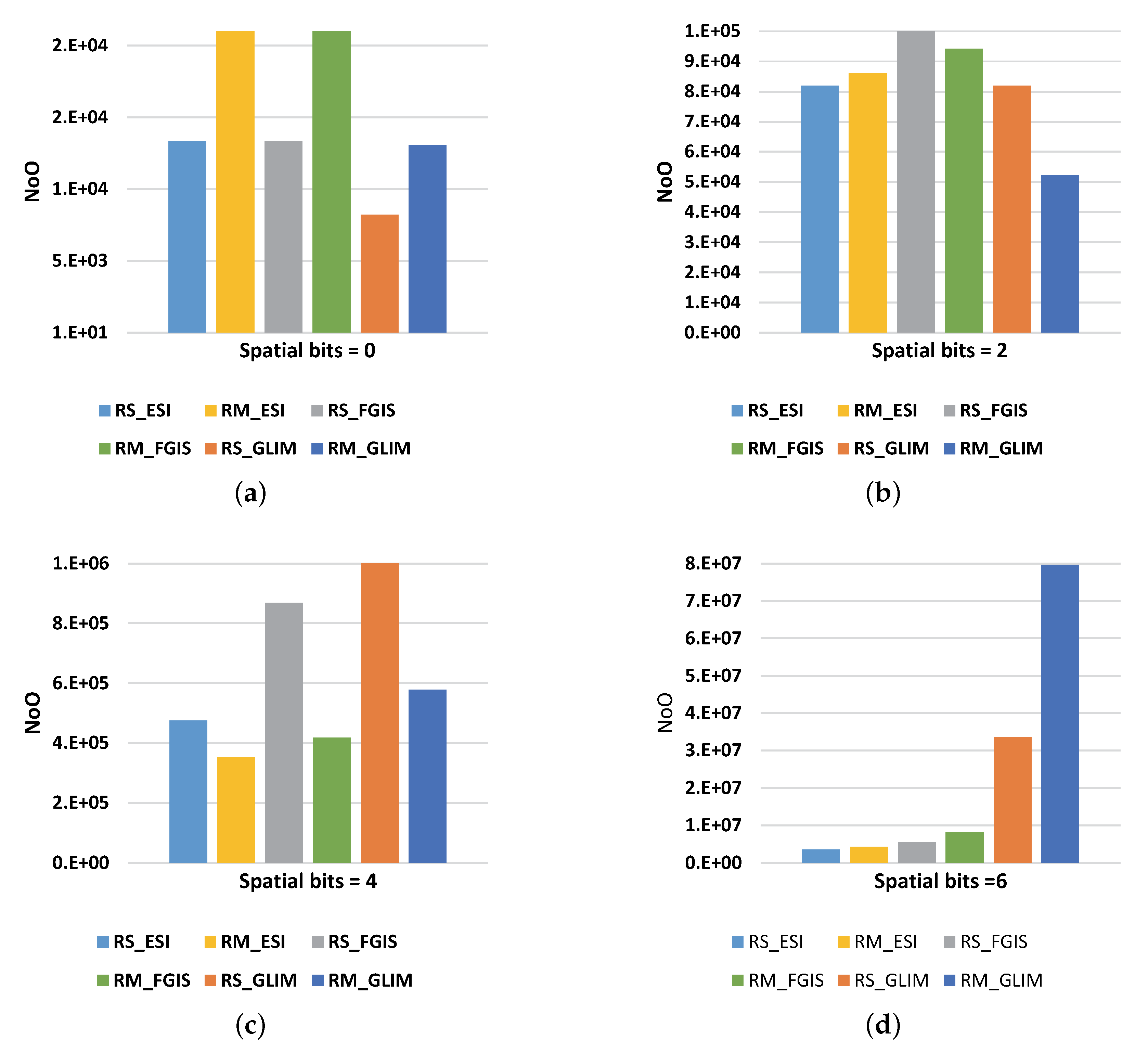
3.3. Computational Complexity

In this section, the computational complexity analyses (CC) of the proposed ESI receiver is evaluated and compared to the FGIS and conventional GLIM-OFDM receivers CC. The CC of ESI receiver is given by calculating the total number of the real multiplication (RM) and real summation (RS) that are required at its decoder. The main difference between the computational complexity of the proposed ESI or FGIS and GLIM is in the number of real operations required to calculate ( h i R ) in (7), and the CC of the MAP metric to determine the indices of the active LEDs. Based on [31], there is no need to compute all the variables in (16) as the optical indoor channel is a time-invariant channel and the indoor VLC channel state information is assumed to be known at the receiver side. Thus, the only parameters that need to be computed are just two parameters C and D in (16). To estimate the real channel path gains in (17), C , and D are computed for every received OFDM subcarrier, while the other parameters i.e., A , B , and E are pre-computed for all possible LED indices ( i ˜ R , and i ˜ I ) and stored in the receiver.
For fair comparison, the CC of the proposed ESI, the FGIS, and the GLIM [31] must be estimated at the same achievable data rate R. Therefore, at the same modulation order M, the proposed ESI, the FGIS, and the GLIM must have the same p to achieve the same R. However, different MIMO LED configurations are employed with ESI, the FGIS, and the GLIM to achieve the same p, where, at a modulation order of 2, i.e., M = 4 , a 4 × 4 MIMO LED configuration is needed for the proposed ESI to achieve a rate of 4 bpcu ( R = 4 ), while 5 × 5 and 16 × 16 MIMO LEDs are needed with the FGIS and GLIM, respectively, to achieve the same rate R at the same M as shown in Figure 3.
For the proposed ESI with p, there will be 2 p + 2 possible joint power allocation and LED combinations ( i ˜ R , and i ˜ I ) with n t E S I × n r E S I MIMO LED configuration. Thus, the number of real summation (RS) and number of real multiplication (RM) needed to decode any OFDM subcarrier ( N t i ) are dependent on RS and RM needed to find C , and D in (16) plus the number of RS and RM needed to estimate the active LED indices i.e., i ˜ R , and i ˜ I .
To find C and D in (16), the number of RS and RM needed are 2 p + 2 ( n t E S I n r E S I ) and 2 p + 2 ( 2 n r E S I + 3 ) , respectively. RS and RM are computed based on the values of C and D in (16), where the value of N i R is set to be equal to n t E S I , which gives the upper limit for RS and RM. Moreover, to estimate the active LED indices i.e., i ˜ R , and i ˜ I (17) under the same aforesaid assumptions, a 2 p + 2 × 4 and a 2 p + 2 × 8 RS and RM are needed, respectively. Therefore, the total number RS and RM needed to decode an OFDM symbol with N T subcarrier are given as follows:
R S E S I = 2 p + 2 ( n t E S I n r E S I + 4 ) N T + 4 l o g 2 ( N T ) ,
R M E S I = 2 p + 2 ( 2 n r E S I + 11 ) N T + 4 N T l o g 2 ( N T ) ,
where 4 l o g 2 ( N T ) and 4 N T l o g 2 ( N T ) are the number of RS and RM needed for decoding the OFDM symbol, respectively.
Likewise, the FGIS [33] CC (the total number RS and RM) can be estimated by the same aforementioned Equations (24) and (25), as the FGIS and the proposed ESI decoders have the same working mechanism. However, the computational complexity of FGIS is larger than the CC of the proposed ESI because the FGIS needs more LEDs to fulfill the same SE of the proposed ESI.
The number of RS and RM of the conventional GLIM were R S = β ( n r + 4 ) N T + 4 l o g 2 ( N T ) , and R M = β ( 2 n r + 11 ) N T + 4 N T l o g 2 ( N T ) [31], respectively, where β = 4 is the GLIM indices combinations and n r = 4 , which gives R S = 32 N T + 4 l o g 2 ( N T ) , and R M = 76 N T + 4 N T l o g 2 ( N T ) [31].
Since the GLIM was adapted in [33] to support spatial modulation with its normal functionality, the computational complexity of the GLIM with p can be given by
R S G L I M = 2 p β ( n r G L I M + 4 ) N T + 4 l o g 2 ( N T ) ,
R M G L I M = 2 p β ( 2 n r G L I M + 11 ) N T + 4 N T l o g 2 ( N T ) ,
where n r G L I M is the PD number at the GLIM receiver, and it is equal to the number of LEDs n t G L I M on the GLIM transmitter side.
Note that, at the same p, the number of LEDs n t G L I M at the GLIM transmitter side is much bigger than the proposed ESI transmitter side or n t G L I M > > n t E S I .
In accordance with the above CC analysis, the number of operations (NoO) for both the proposed ESI, the FGIS, and the GLIM are evaluated and compared against different numbers of p ( i.e., different achievable data rate). The NoO of both the ESI, the FGIS, and the GLIM are piloted with OFDM subcarriers equal to N T = 256 against different values of spatial bits i.e., 0, 2, 4, and 6 as shown in Figure 7a–d, respectively.
At p = 0 spatial bits, the GLIM, FGIS, and ESI were achieved R = l o g 2 ( M ) bpcu data rate, while they used different MIMO configurations i.e., the GLIM, FGIS, and ESI used 4 × 4 , 3 × 3 , and 3 × 3 MIMO LEDs configurations, respectively. Under the aforesaid parameters, the computational complexity of proposed ESI is the same as the CC of the FGIS since they used the same 3 × 3 MIMO LEDs. However, ESI and FGIS are 40 % higher than the GLIM as shown in Figure 7a, while the computational complexity margin between the ESI and the GLIM is reduced to 20 % as the spatial bit increased (i.e., p = 2 ) as shown in Figure 7b. Moreover, the ESI achieves about 12 % CC reduction compared to the FGIS as shown in Figure 7b. However, the proposed ESI CC improved compared to the FGIS and GLIM computational complexity as the number of spatial bits increases. For example, the NoO of ESI reduced by 51 % , and 80 % compared to the GLIM as shown in Figure 7c,d, respectively, while it reduced by 40 % , and 55 % compared to the FGIS as shown in Figure 7c,d, respectively.
On average, the CC of the proposed ESI is reduced by 30 % and 77 . 5 % compared to the FGIS and GLIM, respectively, as Figure 7 shows. This is back-dated to the different nature of increment of the MIMO LEDs branches in ESI, FGIS, and GLIM, where the number of MIMO LEDs branches is increased exponentially with the increment of the spatial bits in the GLIM (see (22), while it increases linearly with the FGIS and semi-linearly in the proposed ESI.
For instance, the GLIM needs theoretically 16 × 16 , 64 × 64 , and 256 × 256 MIMO-LED configurations to achieve spatial bits of p = 2 , p = 4 , and p = 6 bpcu, respectively. Furthermore, the FGIS needs a 5 × 5 , 7 × 7 , and 9 × 9 MIMO-LED configurations to achieve spatial bits of p = 2 , p = 4 , and p = 6 bpcu, respectively, while the proposed ESI needs 4 × 4 , 5 × 5 , and 7 × 7 MIMO-LEDs configurations to achieve the same aforementioned spatial bits, respectively.
Since, according to (24)–(27) the number of LEDs-MIMO branches is the main player in CC analysis, CC of the GLIM increases exponentially compared to the CC of the proposed ESI as shown in Figure 7.

4. Conclusions

The extended spatial-index LED (ESI-LED) modulation scheme for the optical MIMO-OFDM was proposed in this paper. In the proposed ESI, there are no restrictions on the number of LEDs (i.e., any number of LEDs greater than or equal three can be used). Moreover, the proposed ESI is spectrally efficient optical wireless modulation scheme, where its obtainable data rates are semi-nonlinearly increased with n t (LEDs number). The main ESI connotation is to use variable power allocations with a changeable LED indices to convey information, whereas the LED number that is used for data conveyance is changed from the state where only two LED indices are selected to the state where multiple LED indices are selected. At the same time, a variable power allocation of the OFDM real competent is exploited over the same active LED indices. This gives an extra degree of freedom to expand the LED indices spatial domain, which improves the SE of the ESI over GLIM and the FGIS. Moreover, a simple and efficient MAP estimator was proposed for the ESI to cope with the variation on the channel paths (LEDs) number and the real part power allocation. Furthermore, the proposed ESI computational complexity is much better than the GLIM computational complexity especially at the high value of spatial bits. Finally, the simulation results illustrate the ESI efficiency, as it achieves up to 5.2 and 3.7 dB SNR saving compared to the GLIM and the FGIS systems, respectively.

Author Contributions

Conceptualization, H.S.H.; Formal analysis, H.S.H. and M.F.; Funding acquisition, M.F.; Investigation, H.S.H., M.H. and M.F.; Methodology, H.S.H., M.H. and M.F.; Project administration, M.F.; Resources, H.S.H. and M.F.; Software, H.S.H. and M.H.; Supervision, H.S.H.; Validation, H.S.H. and M.F.; Visualization, H.S.H., M.H. and M.F.; Writing—original draft, M.H.; Writing—review & editing, H.S.H., M.F. All authors have read and agreed to the published version of the manuscript.

Funding

This research is funding from the Deanship of Scientific Research at King Khalid University through General Research Project under grant number (R.G.P.I/143/40).

Acknowledgments

The authors extend their appreciation to the Deanship of Scientific Research at King Khalid University for funding this work through General Research Project under grant number (R.G.P.I/143/40).

Conflicts of Interest

The authors declare no conflict of interest.

References

  1. Cisco Visual Networking Index. Global Mobile Data Traffic Forecast Update, 2015–2020 White Paper; Cisco: San Jose, CA, USA, 2016. [Google Scholar]
  2. Hussein, H.; Elsayed, M.; Fakhry, M.; Sayed Mohamed, U. Energy and Spectrally Efficient Modulation Scheme for IoT Applications. Sensors 2018, 18, 4382. [Google Scholar] [CrossRef] [Green Version]
  3. Komine, T.; Nakagawa, M. Fundamental analysis for visible-light communication system using LED lights. IEEE Trans. Consum. Electron. 2004, 50, 100–107. [Google Scholar] [CrossRef]
  4. Tsonev, D.; Videv, S.; Haas, H. Light fidelity (Li-Fi): Towards all-optical networking. In Broadband Access Communication Technologies VIII; International Society for Optics and Photonics: San Francisco, CA, USA, 2014; Volume 9007, p. 900702. [Google Scholar]
  5. Hussein, H.S. Optical Polar Based MIMO-OFDM with Fully Generalized Index-Spatial LED Modulation. IET Commun. 2019, 14, 282–289. [Google Scholar] [CrossRef]
  6. Elgala, H.; Mesleh, R.; Haas, H. Indoor optical wireless communication: Potential and state-of-the-art. IEEE Commun. Mag. 2011, 49, 56–62. [Google Scholar] [CrossRef]
  7. Elgala, H.; Mesleh, R.; Haas, H.; Pricope, B. OFDM visible light wireless communication based on white LEDs. In Proceedings of the 2007 IEEE 65th Vehicular Technology Conference-VTC2007-Spring, Dublin, Ireland, 22–25 April 2007; pp. 2185–2189. [Google Scholar]
  8. Bao, X.; Yu, G.; Dai, J.; Zhu, X. Li-Fi: Light fidelity—A survey. Wirel. Netw. 2015, 21, 1879–1889. [Google Scholar] [CrossRef]
  9. Ashok, A.; Gruteser, M.; Mandayam, N.; Silva, J.; Varga, M.; Dana, K. Challenge: Mobile optical networks through visual MIMO. In Proceedings of the Sixteenth Annual International Conference on Mobile Computing and Networking, Chicago, IL, USA, 20–24 September 2010; pp. 105–112. [Google Scholar]
  10. Varga, M.; Ashok, A.; Gruteser, M.; Mandayam, N.; Yuan, W.; Dana, K. Visual MIMO based led-camera communication applied to automobile safety. In Proceedings of the 9th International Conference on Mobile Systems, Applications, and Services, Bethesda, MD, USA, 28 June–1 July 2011; pp. 383–384. [Google Scholar]
  11. Ashok, A.; Gruteser, M.; Mandayam, N.; Dana, K. Characterizing multiplexing and diversity in visual MIMO. In Proceedings of the 2011 45th Annual Conference on Information Sciences and Systems, Baltimore, MD, USA, 23–25 March 2011; pp. 1–6. [Google Scholar]
  12. Armstrong, J.; Lowery, A.J. Power efficient optical OFDM. Electron. Lett. 2006, 42, 370–372. [Google Scholar] [CrossRef] [Green Version]
  13. Armstrong, J. OFDM for optical communications. J. Lightwave Technol. 2009, 27, 189–204. [Google Scholar] [CrossRef]
  14. Tanaka, Y.; Komine, T.; Haruyama, S.; Nakagawa, M. Indoor visible communication utilizing plural white LEDs as lighting. In Proceedings of the 12th IEEE International Symposium on Personal, Indoor and Mobile Radio Communications, PIMRC 2001, Proceedings (Cat. No.01TH8598), San Diego, CA, USA, 3 October–30 September 2001. [Google Scholar] [CrossRef]
  15. Fernando, N.; Hong, Y.; Viterbo, E. Flip-OFDM for optical wireless communications. In Proceedings of the 2011 IEEE Information Theory Workshop, Paraty, Brazil, 16–20 October 2011; pp. 5–9. [Google Scholar] [CrossRef] [Green Version]
  16. Ding, J.; Xu, Z.; Hanzo, L. Accuracy of the point-source model of a multi-LED array in high-speed visible light communication channel characterization. IEEE Photonics J. 2015, 7, 1–14. [Google Scholar] [CrossRef]
  17. Wang, Q.; Wang, Z.; Dai, L. Multiuser MIMO-OFDM for visible light communications. IEEE Photonics J. 2015, 7, 1–11. [Google Scholar] [CrossRef]
  18. Werfli, K.; Chvojka, P.; Ghassemlooy, Z.; Hassan, N.B.; Zvanovec, S.; Burton, A.; Haigh, P.A.; Bhatnagar, M.R. Experimental Demonstration of High-Speed 4 × 4 Imaging Multi-CAP MIMO Visible Light Communications. J. Lightwave Technol. 2018, 36, 1944–1951. [Google Scholar] [CrossRef] [Green Version]
  19. Foschini, G.J.; Gans, M.J. On limits of wireless communications in a fading environment when using multiple antennas. Wirel. Pers. Commun. 1998, 6, 311–335. [Google Scholar] [CrossRef]
  20. O’Brien, D.C.; Quasem, S.; Zikic, S.; Faulkner, G.E. Multiple input multiple output systems for optical wireless: challenges and possibilities. In Free-Space Laser Communications VI; International Society for Optics and Photonics: San Diego, CA, USA, 2006; Volume 6304, p. 630416. [Google Scholar]
  21. Takase, D.; Ohtsuki, T. Optical wireless MIMO communications (OMIMO). In Proceedings of the 2004 IEEE Global Telecommunications Conference, GLOBECOM’04, Dallas, TX, USA, 29 November–3 December 2004; Volume 2, pp. 928–932. [Google Scholar]
  22. O’Brien, D. Multi-input multi-output (MIMO) indoor optical wireless communications. In Proceedings of the 2009 Conference Record of the Forty-Third Asilomar Conference on Signals, Systems and Computers, Pacific Grove, CA, USA, 1–4 November 2009; pp. 1636–1639. [Google Scholar]
  23. Azhar, A.H.; Tran, T.A.; O’Brien, D. A gigabit/s indoor wireless transmission using MIMO-OFDM visible-light communications. IEEE Photonics Technol. Lett. 2012, 25, 171–174. [Google Scholar] [CrossRef]
  24. Burton, A.; Haigh, P.A.; Chvojka, P.; Ghassemlooy, Z.; Zvánovec, S. Filter-less WDM for visible light communications using colored pulse amplitude modulation. Opt. Lett. 2019, 44, 4849–4852. [Google Scholar] [CrossRef] [PubMed]
  25. Younis, A.; Serafimovski, N.; Mesleh, R.; Haas, H. Generalised spatial modulation. In Proceedings of the 2010 Conference Record of the Forty Fourth Asilomar Conference on Signals, Systems and Computers, Pacific Grove, CA, USA, 7–10 November 2010; pp. 1498–1502. [Google Scholar]
  26. Hussein, H.; Esmaiel, H.; Jiang, D. Fully generalised spatial modulation technique for underwater communication. Electron. Lett. 2018, 54, 907–909. [Google Scholar] [CrossRef]
  27. Hussein, H.S.; Elsayed, M. Fully-Quadrature Spatial Modulation. In Proceedings of the IEEE International Black Sea Conference on Communications and Networking (BlackSeaCom), Batumi, Georgia, 4–7 June 2018; pp. 1–5. [Google Scholar]
  28. Hussein, H.S.; Elsayed, M.; Mohamed, U.S.; Esmaiel, H.; Mohamed, E.M. Spectral Efficient Spatial Modulation Techniques. IEEE Access 2019, 7, 1454–1469. [Google Scholar] [CrossRef]
  29. Mesleh, R.; Elgala, H.; Haas, H. Optical spatial modulation. J. Opt. Commun. Netw. 2011, 3, 234–244. [Google Scholar] [CrossRef]
  30. Li, Y.; Tsonev, D.; Haas, H. Non-DC-biased OFDM with Optical Spatial Modulation. In Proceedings of the 2013 IEEE 24th Annual International Symposium on Personal, Indoor, and Mobile Radio Communications (PIMRC), London, UK, 8–11 September 2013; pp. 486–490. [Google Scholar] [CrossRef]
  31. Yesilkaya, A.; Basar, E.; Miramirkhani, F.; Panayirci, E.; Uysal, M.; Haas, H. Optical MIMO-OFDM With Generalized LED Index Modulation. IEEE Trans. Commun. 2017, 65, 3429–3441. [Google Scholar] [CrossRef]
  32. Le Tran, M.; Kim, S.; Ketseoglou, T.; Ayanoglu, E. LED Selection and MAP Detection for Generalized LED Index Modulation. IEEE Photonics Technol. Lett. 2018, 30, 1695–1698. [Google Scholar] [CrossRef]
  33. Hussein, H.S.; Hagag, M. Optical MIMO-OFDM With Fully Generalized Index-Spatial LED Modulation. IEEE Commun. Lett. 2019, 23, 1556–1559. [Google Scholar] [CrossRef]
  34. Dimitrov, S.; Haas, H. Principles of LED lIght Communications: Towards Networked Li-Fi; Cambridge University Press: Cambridge, UK, 2015. [Google Scholar]
  35. Chvojka, P.; Zvanovec, S.; Haigh, P.A.; Ghassemlooy, Z. Channel Characteristics of Visible Light Communications Within Dynamic Indoor Environment. J. Lightwave Technol. 2015, 33, 1719–1725. [Google Scholar] [CrossRef]
  36. Komine, T.; Haruyama, S.; Nakagawa, M. A study of shadowing on indoor visible-light wireless communication utilizing plural white LED lightings. Wirel. Pers. Commun. 2005, 34, 211–225. [Google Scholar] [CrossRef]
  37. Miramirkhani, F.; Uysal, M. Channel modeling and characterization for visible light communications. IEEE Photonics J. 2015, 7, 1–16. [Google Scholar] [CrossRef]
  38. Yuan, W.; Li, X.; Gao, X.; Yuan, J.; Yang, Y.; Wang, Y. Mirco Signal Wireless-communication Device based on GaN-on-Silicon platform with light emitting Diodes. In Proceedings of the 2017 IEEE International Conference on Robots & Intelligent System (ICRIS), Huai’an, China, 15–16 October 2017; pp. 210–213. [Google Scholar]
  39. Zhao, W.; Yu, H.; Wen, Y.; Wang, F.; Yang, Y.; Liu, Z.; Liu, L.; Li, W.J. Detection of micro/nano-particle concentration using modulated light-emitting diode white light source. Sens. Actuators A Phys. 2019, 285, 89–97. [Google Scholar] [CrossRef]
  40. Jeganathan, J.; Ghrayeb, A.; Szczecinski, L.; Ceron, A. Space shift keying modulation for MIMO channels. IEEE Trans. Wirel. Commun. 2009, 8, 3692–3703. [Google Scholar] [CrossRef] [Green Version]
Figure 1. The extended spatial-index light emitting diode (ESI-LED) modulation system structure with n t × n r configuration.
Electronics 09 00168 g001
Figure 2. Configuration A (PD in the center of the table), B (PD at the corners of the table) and C (PD are aligned to their correspondent LED.
Electronics 09 00168 g002
Figure 3. The proposed ESI, the GLIM [31], and the FGIS [33] achievable data rates at very high S N R .
Electronics 09 00168 g003
Figure 4. Scenario 1: The ABER of the proposed ESI compared to GLIM [31] at the same modulation orders, but with different MIMO-LED configurations for three physical channels, A, B, and C.
Electronics 09 00168 g004
Figure 5. Scenario 2 test 1 ABER of the proposed ESI compared to GLIM [31] and FGIS [33] at the same MIMO-LED configurations, but with different modulation orders (M) to achieve the same SE for three physical channels A, B and C.
Electronics 09 00168 g005
Figure 6. Scenario 2 test 2 ABER of the proposed ESI compared to GLIM [31] and FGIS [33] at the same MIMO-LEDs configurations, but with different modulation orders to achieve the same SE for three physical channels A, B, and C.
Electronics 09 00168 g006aElectronics 09 00168 g006b
Figure 7. Computational complexity of the proposed ESI compared with the CC of the FGIS [33] and the GLIM [31] at different achievable data rates: (a) l o g 2 ( M ) (zero spatial bits); (b) l o g 2 ( M ) + 2 (two spatial bits); (c) l o g 2 ( M ) + 4 (four spatial bits) and (d) l o g 2 ( M ) + 6 (six spatial bits).
Electronics 09 00168 g007
Table 1. Example for the ESI-LED transmission mechanism for n t = 4 .
DataTransmitted Data
G /SB OFDM td TX LED 1 TX LED 2 TX LED 3 TX LED 4
1 / 00 c n R + j c n I c n R c n I --
c n R j c n I c n R - c n I -
c n R + j c n I c n R -- c n I
c n R j c n I - c n R c n I -
2 / 01 c n R + j c n I - c n R - c n I
c n R j c n I -- c n R c n I
c n R + j c n I c n R / 2 c n R / 2 c n I -
c n R j c n I c n R / 2 c n I c n R / 2 -
3 / 10 c n R + j c n I c n I c n R / 2 c n R / 2 -
c n R j c n I c n R / 2 c n R / 2 - c n I
c n R + j c n I c n R / 2 c n I - c n R / 2
c n R j c n I c n I c n R / 2 - c n R / 2
4 / 11 c n R + j c n I c n R / 2 - c n R / 2 c n I
c n R j c n I c n R / 2 - c n I c n R / 2
c n R + j c n I c n I - c n R / 2 c n R / 2
c n R j c n I - c n R / 2 c n R / 2 c n I
Table 2. Example for the ESI-LED transmission mechanism for n t = 5 .
DataTransmitted Data
G /SB OFDM td TX LED 1 TX LED 2 TX LED 3 TX LED 4 TX LED 5
1 / 0000 c n R + j c n I c n R c n I ---
c n R j c n I c n R - c n I --
c n R + j c n I c n R -- c n I -
c n R j c n I c n R --- c n I
2 / 0001 c n R + j c n I - c n R c n I --
c n R j c n I - c n R - c n I -
c n R + j c n I - c n R -- c n I
c n R j c n I -- c n R c n I -
3 / 0010 c n R + j c n I -- c n R - c n I
c n R j c n I --- c n R c n I
c n R + j c n I c n R / 2 c n R / 2 c n I --
c n R j c n I c n R / 2 c n I c n R / 2 --
4 / 0011 c n R + j c n I c n I c n R / 2 c n R / 2 --
c n R j c n I c n R / 2 c n R / 2 - c n I -
c n R + j c n I c n R / 2 c n I - c n R / 2 -
c n R j c n I c n I c n R / 2 - c n R / 2 -
5 / 0100 c n R + j c n I c n R / 2 c n R / 2 -- c n I
c n R j c n I c n R / 2 c n I -- c n R / 2
c n R + j c n I c n I c n R / 2 -- c n R / 2
c n R j c n I c n R / 2 - c n R / 2 c n I -
6 / 0101 c n R + j c n I c n R / 2 - c n I c n R / 2 -
c n R j c n I c n I - c n R / 2 c n R / 2 -
c n R + j c n I c n R / 2 - c n R / 2 - c n I
c n R j c n I c n R / 2 - c n I - c n R / 2
7 / 0110 c n R + j c n I c n I - c n R / 2 - c n R / 2
c n R j c n I c n R / 2 -- c n R / 2 c n I
c n R + j c n I c n R / 2 -- c n I c n R / 2
c n R j c n I c n I -- c n R / 2 c n R / 2
8 / 0111 c n R + j c n I - c n R / 2 c n R / 2 c n I -
c n R j c n I - c n R / 2 c n I c n R / 2 -
c n R + j c n I - c n I c n R / 2 c n R / 2 -
c n R j c n I - c n R / 2 c n R / 2 - c n I
9 / 1000 c n R + j c n I - c n R / 2 c n I - c n R / 2
c n R j c n I - c n I c n R / 2 - c n R / 2
c n R + j c n I - c n R / 2 - c n R / 2 c n I
c n R j c n I - c n R / 2 - c n I c n R / 2
10 / 1001 c n R + j c n I - c n I - c n R / 2 c n R / 2
c n R j c n I -- c n R / 2 c n R / 2 c n I
c n R + j c n I -- c n R / 2 c n I c n R / 2
c n R j c n I -- c n I c n R / 2 c n R / 2
11 / 1010 c n R + j c n I c n I c n R / 3 c n R / 3 c n R / 3 -
c n R j c n I c n R / 3 c n I c n R / 3 c n R / 3 -
c n R + j c n I c n R / 3 c n R / 3 c n I c n R / 3 -
c n R j c n I c n R / 3 c n R / 3 c n R / 3 c n I -
12 / 1011 c n R + j c n I c n I c n R / 3 c n R / 3 - c n R / 3
c n R j c n I c n R / 3 c n I c n R / 3 - c n R / 3
c n R + j c n I c n R / 3 c n R / 3 c n I - c n R / 3
c n R j c n I c n R / 3 c n R / 3 c n R / 3 - c n I
13 / 1100 c n R + j c n I c n I c n R / 3 - c n R / 3 c n R / 3
c n R j c n I c n R / 3 c n I - c n R / 3 c n R / 3
c n R + j c n I c n R / 3 c n R / 3 - c n I c n R / 3
c n R j c n I c n R / 3 c n R / 3 - c n R / 3 c n I
14 / 1101 c n R + j c n I c n I - c n R / 3 c n R / 3 c n R / 3
c n R j c n I c n R / 3 - c n I c n R / 3 c n R / 3
c n R + j c n I c n R / 3 - c n R / 3 c n I c n R / 3
c n R j c n I c n R / 3 - c n R / 3 c n R / 3 c n I
15 / 1110 c n R + j c n I - c n I c n R / 3 c n R / 3 c n R / 3
c n R j c n I - c n R / 3 c n I c n R / 3 c n R / 3
c n R + j c n I - c n R / 3 c n R / 3 c n I c n R / 3
c n R j c n I - c n R / 3 c n R / 3 c n R / 3 c n I
16 / 1111 c n R + j c n I c n I c n R / 4 c n R / 4 c n R / 4 c n R / 4
c n R j c n I c n R / 4 c n I c n R / 4 c n R / 4 c n R / 4
c n R + j c n I c n R / 4 c n R / 4 c n I c n R / 4 c n R / 4
c n R j c n I c n R / 4 c n R / 4 c n R / 4 c n I c n R / 4
Table 3. The physical VLC channel parameters [31].
ParametersValues
Dimensions of the room5 m × 5 m × 3 m
Number of Luminaries4
Number of LED Chips per Luminary9
Model of LED ChipsCree Xlamp MC-E White
Power of LED Chips5 W
Luminary (L) Positions (x, y, z) (m)L1: (−1.3, −0.7, 3) L2: (−1.3, 1.3, 3) L3: (0.7, 1.3, 3)
L4: (0.7, −0.7, 3)
Photo detector (PD) positions (x, y, z) (m)Config A: PD1: (−0.05, −0.05, 0.8)
PD2: (−0.05, 0.05, 0.8) PD3: (0.05, 0.05, 0.8)
PD4: (0.05, −0.05, 0.8)
Config B: PD1: (−0.4, −0.4, 0.8)
PD2: (−0.4, 0.4, 0.8) PD3: (0.4, 0.4, 0.8)
PD4: (0.4, −0.4, 0.8)
Config C: located at center of table with
equidistant 0.1 m and rotated by 45
in xy-plane and titled by 60
View of angle of Luminary 120
FOV of PD 85
Area of PD1 cm 2
MaterialsWalls & Ceiling: Plaster Floor & Desk:
Pine Wood

