Article

An Efficient Precoding Scheme for Millimeter-Wave Massive MIMO Systems

1
School of Computing & Informatics, Al-Hussein Technical University KHBP, Amman 11855, Jordan
2
Department of Electrical Engineering, The Hashemite University, Zarqa 13133, Jordan
3
Department of Electrical Engineering, University of Engineering & Technology Peshawar, P.O. Box 814 Peshawar, Pakistan
4
School of Physics and Electronic Information Engineering, Henan Polytechnic University, Jiaozuo 454000, China
5
School of Electrical and Electronics Engineering, Chung-Ang University, Seoul 156-756, Korea
*
Author to whom correspondence should be addressed.
Electronics 2019, 8(9), 927; https://doi.org/10.3390/electronics8090927
Submission received: 23 July 2019 / Revised: 20 August 2019 / Accepted: 22 August 2019 / Published: 24 August 2019
(This article belongs to the Section Microwave and Wireless Communications)

Abstract

:
Aiming at the problem of high computational complexity due to a large number of antennas deployed in mmWave massive multiple-input multiple-output (MIMO) communication systems, this paper proposes an efficient algorithm for optimizing beam control vectors with low computational complexity based on codebooks for millimeter-wave massive MIMO systems with split sub-arrays hybrid beamforming architecture. A bidirectional method is adopted on the beam control vector of each antenna sub-array both at the transmitter and receiver, which utilizes the idea of interference alignment (IA) and alternating optimization. The simulation results show that the proposed algorithm has low computational complexity, fast convergence, and improved spectral efficiency as compared with the state-of-the-art algorithms.

1. Introduction

Millimeter wave multiple-input multiple-output (MIMO) communication enabling high speed and high quality without line communication transmission has become a hot spot of global attention [1,2]. Due to the short wavelength of millimeter wave, the antenna array can be integrated into a millimeter wave communication system. However, the shorter wavelength also brings serious path loss [3,4], and the application of beamforming becomes a compensation path loss strategy to improve transmission quality. The pre-coded data stream transmitted in the single-user communication system can increase the transmission rate of the system. In the multi-user communication system, pre-coding processing can eliminate inter-user interference (IUI) and improve the transmission quality of the system. Although beamforming can improve the transmission quality of the system and increase the spectral efficiency of the system, beamforming also has many problems in millimeter wave communication systems. In the pure digital domain MIMO communication system, the baseband uses digital beamforming to control the phase and amplitude of the signal well, but a transmitting antenna needs to be connected to a radio frequency (RF) link. As the number of transmitting antennas increases, the RF links are also increasing, so that the cost of the system and power consumption is too high [5]. In the analog domain, an analog precoder consisting of an inexpensive phase shifter can reduce the number of RF links, and the corresponding overhead is also reduced. However, due to the constraints of the phase shifter itself, the elements in the analog precoding matrix need to satisfy the amplitude. It is a constant constraint so the performance achieved by analog beamforming technology will be limited [6]. Simultaneous use of beamforming in the digital domain and the analog domain can reduce the overhead of the system and compensate for the defects of analog beamforming, making hybrid beamforming a first pre-coding technique [7,8,9,10,11,12,13,14,15,16]. It can be seen from literature [5] that the hybrid beamforming architecture includes a separate sub-array architecture and a shared architecture. The signal on each transmit antenna in the shared architecture is a hybrid superposition of signals on all RF links, and one RF link needs to drive all transmitting antenna. Compared with the shared architecture, one RF link in a separate sub-array architecture is connected to only one antenna sub-array, and each RF link only needs to drive a transmit antenna on the sub-array connected thereto, so the separate sub-array architecture system can effectively reduce energy consumption and hardware complexity. Literature [8] analyzed the relationship between digital beamforming and hybrid beamforming and compared its performance. In [9], an algorithm for determining the sub-array analog beam control vector based on the codebook matching beam pair is proposed for the separate sub-array architecture system. However, the algorithm requires more beam training times, so that it has a high degree of complexity. In [10], both the transmitting and receiving ends are shared hybrid beamforming architectures, and an orthogonal matching pursuit (OMP) algorithm for simultaneous beamforming and digital beamforming is proposed for hybrid beamforming architecture. In [12], based on the codebook with the maximum received power as the criterion, the beamforming method is used to solve the analog beamforming, and then the equivalent channel is used to solve the digital beamforming.
Applying interference alignment ideas [17,18,19] in wireless networks can achieve higher system capacity. By integrating multiple interfering signals into a small subspace at the receiving end, maximizing the number of non-interfering dimensions remaining in the desired signal minimizes the impact of the interfering signal on the desired signal while maximizing the desired signal energy. For the multi-user interference channel communication system, the literature [17] proposed two algorithms for solving the digital precoding matrix and the digital combining matrix based on the idea of interference alignment. The first algorithm reduces the interference signal space solution by minimizing the signal leakage energy of each user. The second improved algorithm increases the expected signal space solution by maximizing the received signal to interference ratio of each user. The results show that the interference alignment can be achieved more effectively by minimizing the signal leakage energy or maximizing the received signal to interference and noise ratio (SINR).
Based on this idea, this paper adopts the architecture of the sub-array hybrid beamforming of the transmitting end and the receiving end and a low complexity codebook based and signal to interference and noise ratio (SINR) maximization sub-array beam control vector algorithm is proposed. According to the reciprocity characteristic of the channel, the optimization algorithm is used to alternately optimize the analog beamforming vectors of the receiving end and the transmitting end antenna sub-array to determine the analog beamforming part, thereby determining the digital beamforming part. The split sub-array hybrid beamforming transmission scheme based on the proposed algorithm achieves a good trade-off between the performance and complexity. The sub-array beam control vector is optimized, the interference between sub-arrays is reduced, and the performance achieved by the proposed algorithm is gradually improved as the number of RF links increases. At the same time, the complexity of the proposed algorithm is compared with other codebook-based optimized beam control vector algorithms and analyze the maximum SINR convergence corresponding to the antenna sub-array. The complexity comparison and SINR convergence analysis strongly illustrate that the proposed algorithm has low complexity and fast convergence.
The rest of the paper is organized as follows. Section 2 describes the system model. Section 3 explains the proposed algorithm. Section 4 provides the simulation results and discussions while Section 5 concludes the paper.

2. System Model

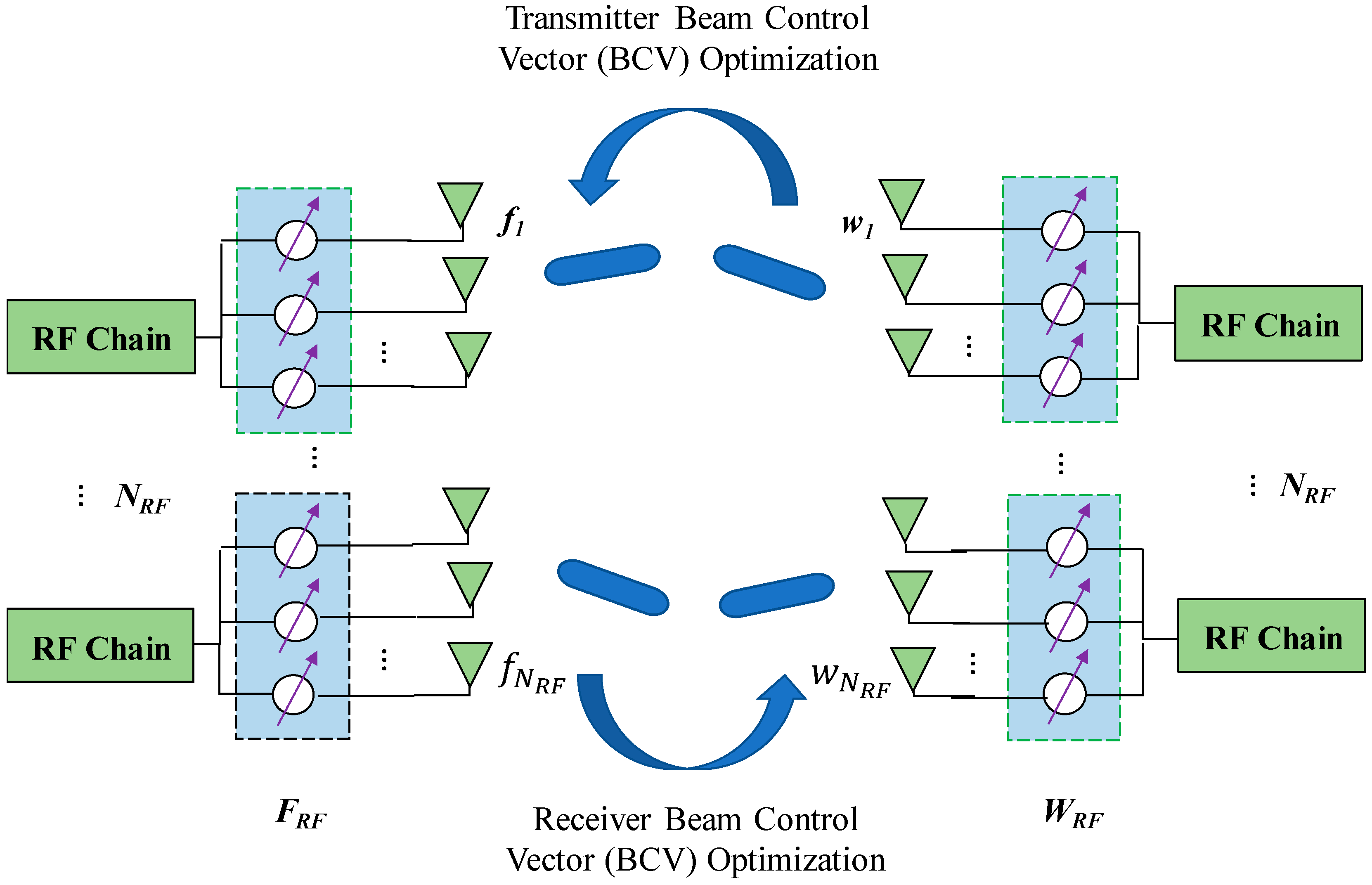
Although the performance of the hybrid sub-array architecture hybrid beamforming is worse than that of the shared architecture hybrid beamforming, its implementation is simple and the energy consumption is low. The hybrid beamforming research of the split sub-array architecture is more practical. In this paper, we consider a single-user mmWave MIMO communication system with antenna sub-array hybrid beamforming architecture at both the transmitting end and the receiving end, that is, one RF link is connected to one antenna sub-array, and one antenna is connected to a phase shifter, as shown in Figure 1.
The transmitting end is driven by the N R F RF link to transmit N S data streams. The number of transmitting antennas of the i-th sub-array is N i , and the total number of transmitting antennas is N = i = 1 N R F N i . The data stream is first processed by the digital precoder F B B with the dimension N R F × N S , and then processed by the analog precoder F R F of dimension N × N R F . In order to meet the limitation of the total transmission power, F B B and F R F need to satisfy F R F F B B F 2 N S , where F represents the Frobenius norm. Constrained by the phase shifter of the analog precoder, the elements in the F R F need to satisfy the constant constraint of the amplitude and denoted as F R F = diag ( f 1 , f 2 , , f N R F ) , where f i = 1 N i [ e j φ i , 1 , e j φ i , 2 , , e j φ i , N i ] T is the beam control vector of the i-th transmit sub-array, φ i , m denotes the i-th phase angle of the phase shifter on the m-th antenna of the emitter array, diag   ( · ) represents the block-diagonal matrix, and ( · ) T represents the transpose.
For the sake of simplicity, considering a narrow-band block fading channel model, the signal received at the receiving end can be expressed as:
r = ρ H F R F F B B s + n
where H represents the channel matrix of the downlink M × N and E [ H F 2 ] = N M , where M is the number of receiving antennas at the receiving end, E [ · ] means to find the expected value, s is a normalized transmission data symbol vector of N s × 1 , that is, E [ s s H ] = I N s , where I N s represents the identity matrix of N s × N s , ( · ) H indicates the conjugate transposition, ρ represents the average received power, and n is an additive white Gaussian noise with a mean value of 0 and covariance matrix as σ 2 I distribution. Although the millimeter wave channel transmits a short wavelength, the antenna array can be implemented in a small range. However, the number of scatterers is limited, so that the scattering ability is limited. In this paper, we used the geometric channel model [7,8,20,21], and the channel model H is expressed as follows:
H = N M L   l = 1 L α l α M S ( ϑ l ) α B S H ( θ l )
where L represents the number of channel paths, usually L N R F , α l represents the complex gain of the l -th path, θ l represents the exit angle of the l -th path at the transmitting end, ϑ l represents the angle of arrival of the l -th path at the receiving end, α B S and α M S respectively represent the response vector of the transmitting end and the receiving end antenna array determined by the antenna array structure. For a uniform linear array, the transmit-end array response vector α B S can be expressed as:
α B S ( θ ) = 1 N [ 1 ,   e j 2 π λ d sin ( θ ) ,   ,   e j 2 π λ ( N 1 ) sin ( θ ) ] T
where λ represents the wavelength of the signal and d represents the distance between the antennas. The array response vector α M S representation at the receiving end is similar to the α B S representation.
The N R F antenna sub-array at the receiving end receives N s data streams, and the k -th receiving antenna sub-array is composed of M k antennas. The total number of receiving antennas M = k = 1 N R F M k , and the number of data streams N s should satisfy N s N R F . The received signal is first processed by the analog precoding matrix representation of the transmitting end. The analog combiner W R F can be expressed as W R F = diag   ( w 1 , w 2 , ,   w N R F ) , where w k = 1 M k   [ e j ϕ k , 1 , e j ϕ k , 2 ,   ,   e j ϕ k , M k ] T denotes the beam control vector of the k -th receiving sub-array, ϕ k , n represents the phase angle of the phase shifter on the n -th antenna of the k -th receiving sub-array. The digital W B B restores the signal to a data stream. The dimension of the W B B is N R F × N s , and the signal y processed by the digital at the receiving end can be expressed as:
y = W B B H W R F H r = ρ W B B H W R F H H F R F F B B s + W B B H W R F H n
where y is the data symbol vector received by the receiving end of N s × 1 . Considering that the channel reciprocity characteristics, the uplink channel H ¯ can be directly represented by the downlink channel H , that is, H ¯ = H H , and the signal expression received by the receving end can also be obtained according to the above procedure.
The signal transmitted by the transmitting end is transmitted and processed on the downlink, and the transmission rate realized by the system is:
R = log 2 | I + ρ σ 2 R n 1 W B B H W R F H H F R F F B B F B B H F R F H H H W R F W B B |
where R n = W B B H W R F H W R F W B B , ( · ) 1 indicates the matrix inversion, | · | indicates the determinant, and log 2 ( · ) indicates the base 2 logarithm.
The main purpose of designing hybrid beamforming is to improve the spectral efficiency of the system and optimize the performance of the system by optimizing the precoder. In order to meet the limitation of the total transmission power, F B B and F R F need to satisfy F R F F B B F 2 N S , where F represents the Frobenius norm. Therefore, the specific expression of the objective function is:
max F B B , F R F , W B B , W R F R
Subject to F R F : i F , i = 1 , 2 , , N R F W R F : k W , k = 1 , 2 , , N R F F R F F B B F 2 N S k = 1 N R F F R F F B B [ k ] F 2 P t o t
where F R F : i denotes the i -th column vector of the matrix F R F , W R F : k represents the k -th column vector of the matrix W R F , F , W represents the beam codebook used by the transmitting end and the receiving end, respectively. F B B [ k ] is a N R F × K matrix that represents the digital baseband precoding at the kth subcarrier and P t o t represents the total power in the above constraints. The Frobenius norm is used to determine the mean power gain of the precoders.

3. Algorithm Description

3.1. Notations

( · ) k H indicates conjugate transposition of the k-element, ( · ) k , i represents the corresponding element between the k -th and i -th element. S I N R k r is the SINR of the k-th subarray of the receiver and S I N R k t is the SINR of the k-th subarray of the transmitter. W denotes the codebook of the transmitter and F represents the codebook of the receiver. H ˜ indicates the equivalent channel matrix at the receiver. X k and Δ k are fixed scaler values. f i is the beam control vector of the i-th transmit sub-array. a r g   m a x w k W   ( · ) indicates the maximum value of the argument, which belongs to the codebook W .

3.2. Hybrid Beamforming Design of Low Complexity Split Sub-Array

The beam control vector is solved by analog beam training, and the optimal performance can be achieved by using the exhaustive algorithm [22] to obtain the beam control vector of each sub-array. However, as the number of antenna sub-arrays increases, the excessive algorithm complexity makes the exhaustive algorithm difficult to achieve. In order to reduce the complexity of the system, this paper proposes a low complexity codebook based and signal to interference and noise ratio maximization optimization subarray beam control vector algorithm, which optimizes and determines the analog beamforming part to solve the digital domain beam forming. Using the Discrete Fourier Transform (DFT) codebook designed in [23], each column in the codebook represents an antenna weight vector (AWV). Assuming that the number of antennas is S , the number of antenna weight vectors in the codebook is T , and the specific expression of the beam control vector is:
g ( s , t ) = 1 S e j 2 π ( s 1 ) ( t 1 ) T ,   s = 1 , ,   S ; t = 1 , ,   T .

3.2.1. Proposed Algorithm

The main starting point of this paper to study the fast beam alignment using the interference alignment idea is to try to align the beam direction of the interference sub-array to the same direction, and minimize the interference to the desired signal while trying to maximize the energy of the desired signal. The main goal of this idea can be simply expressed as maximizing the signal to interference and noise ratio of the received signal at the receiving end. Consider designing the beam control vector optimization algorithm with the maximum signal-to-noise ratio as the target, first optimize the beam control vector of the receiving terminal array, and then optimize the beam control vector of the transmitting terminal array according to the reciprocity characteristics of the channel, and determine the SINR corresponding to each sub-array. Whether to converge, if it converges, iterative optimization is stopped, otherwise iteratively optimizes the beam control vector of the transceiver terminal array.
Maximizing the analog beamforming based on the signal to interference and noise ratio (SINR), given the initial analog precoding matrix and the analog combining matrix, fixing the beam direction of each subarray at the transmitting end, first optimizing the beam control vector of the kth subarray at the receiving end, so that the SINR of the signal received by the kth sub-array at the receiving end is the largest, namely:
S I N R k r = a r g   m a x w k W w k H H k , k f k f k H H k , k H w k w k H ( i k N R F H k , i f i f i H H k , i H + σ 2 I ) w k
where H k , i represents the channel between the k -th sub-array of the receiving end and the i -th sub-array of the transmitting end in the downlink. Let X k = H k , k f k f k H H k , k H and Δ k = i k N R F H k , i f i f i H H k , i H + σ 2 I , then Equation (8) can be written as:
S I N R k r = a r g   m a x w k W w k H X k w k w k H Δ k w k
Note that when the beam control vector of the k -th sub-array is determined by beam training, X k and Δ k are fixed values.
According to the reciprocal characteristics of the channel, the beam direction of each sub-array at the receiving end is kept unchanged, and the i -th sub-array beam control vector of the transmitting end is optimized so that the SINR of the received signal is the largest, namely:
S I N R i t = a r g   m a x f i F f i H H ¯ i , i w i w i H H ¯ i , i H f i f i H ( k i N R F H ¯ i , k w k w k H H ¯ i , k H + σ 2 I ) f i
where H ¯ i , k represents the channel between the i -th sub-array of the receiving end and the k -th sub-array of the transmitting end in the uplink, because H ¯ i , i = H i , i H , so Equation (10) can be expressed as:
S I N R i t = a r g   m a x f i F f i H H i , i H w i w i H H i , i f i f i H ( k i N R F H k , i H w k w k H H k , i + σ 2 I ) f i
Let Ω i = H i , i H w i w i H H i . i and Λ i = k i N R F H k , i H w k w k H H k . i + σ 2 I , then Equation (11) can be written as:
S I N R i t = a r g   m a x f i F f i H Ω i f i f i H Λ i f i
where Ω i and Λ i are fixed when determining the beam control vector of the i -th sub-array by beam training.

3.2.2. Power Control Mechanism

The baseband transmit power B n is determined by the present state 𝓈 n and the Q-function. The present state is considered as the previous estimated power and last SINR of the K users. Therefore, the Base Station (BS) transmit power P r can be expressed as:
P r = { 1 ε ,   ^ B   = a r g   m a x B Ψ Q ( 𝓈 n , B ) ε | Ψ | 1 ,   ^ B   a r g   m a x B Ψ Q ( 𝓈 n , B )
where ε is a small positive value between (0,1); B is the baseband power; and | Ψ | represents the total number of iterations. It is assumed that the initial analog precoding matrix, the analog combining matrix, the transmitting end codebook F , and the receiving end codebook W are known, and the optimized subarray beam control vector algorithm based on the codebook (OSBC) and the SINR maximization is shown in Algorithm 1.
Algorithm 1 OSBC Algorithm
1:
Initialization τ = 0 , S I N R k , τ r = 0 , S I N R i , τ t = 0 , F R F , W R F , F , W .
2:
Define the transmitter analog precoding matrix F R F and optimize the beam control vector (BCV) of the k -th sub-array at the receiver.
3:
Perform beam training on the antenna weight vector (AWV) in the codebook W .
4:
Obtain S I N R k , τ + 1 r , and take S I N R k , τ + 1 r corresponding AWV as the beam control vector (BCV) of the k -th ( k = 1 , 2 , N R F ) sub-array via Equation (9).
5:
Define the receiver analog beam matrix W R F and optimize the BCV of the ith ( i = 1 , 2 , N R F ) sub-array at the transmitter.
6:
Perform beam training on the AWV in the codebook F .
7:
Obtain a S I N R i , τ + 1 t via Equation (12), and using an AWV corresponding to the S I N R i , τ + 1 t as a BCV of the i -th ( i = 1 , 2 , N R F ) sub-array.
8:
If | S I N R i , τ + 1 t S I N R i , τ t | ε t , i = 1 , 2 , N R F ,   | S I N R k , τ + 1 r S I N R k r | ε r , k = 1 , 2 , N R F .
9:
Converge and stop iterating.
10:
Otherwise let τ = τ + 1 and return to Step 2.
11:
Determine the baseband power B n according toe SINR and channel channel conditions.
12:
Update Q ( 𝓈 n , B ) via Equation (13).
13:
end
S I N R i , τ t and S I N R k r represent the maximum SINR of the i -th sub-array and the k -th sub-array at the receiving end, respectively, at the firt iteration; ε t and ε r represent the maximum SNR of the transmitting end and the receiving terminal array convergence thresholds. The process of optimizing the analog precoding matrix F R F and the analog combining matrix W R F according to Algorithm 1 is shown in Figure 2, and can be specifically divided into the following three stages:
First Stage: Fixed beam control vector (BCV) of each sub-array at the transmitting end, the transmitting end transmits the same data stream under the same conditions and the k -th ( k = 1 , 2 , N R F ) sub-arrays of the receiving end sequentially use the AWV in W is received, S I N R k r is obtained according to Equation (9), and the AWV corresponding to S I N R k r is used as its BCV.
Second Stage: The BCV of each sub-array at the fixed receiving end, the receiving end transmits the same data stream under the same conditions and the i -th ( i = 1 , 2 , N R F ) antenna sub-array of the transmitting end is sequentially used. The AWV received a signal in the codebook F , the S I N R i t is obtained by the Equation (12), and the AWV corresponding to the S I N R i t is used as its BCV.
Third stage: Judging whether the maximum SINR of each sub-array at the transmitting end and the receiving end satisfies convergence at the same time and stops beam training if it is satisfied at the same time, otherwise the first stage and the second stage are continued.

3.2.3. Digital Beamforming Design

Through the Algorithm 1, the optimized analog precoding matrix F R F and analog combining matrix W R F can be obrained, thereby obtaining the equivalent channel H ˜ = W R F H H F R F of the downlink, performing singular value decomposition (SVD) on the equivalent channel H ˜ , and taking out the maximum N s singularities. The right singular value corresponding to the vlaue is used as the digitan precoding matrix F B B . In the case of the digital precoding matrix and the analog beamforming part, the digital combining matrix is designed as an MMSE receiver, namely:
W B B = G 1 W R F H H F R F F B B
Among them, G = W R F H H F R F F B B F B B H F R F H H H W R F + σ 2 W R F H W R F .

3.2.4. Algorithm Complexity Analysis

In this part, the complexity of Algorithm 1 proposed in Section 3.1 was analyzed and compared with other code-based algorithm complexity. By comparison, it could be concluded that Algorithm 1 had low complexity. When the number of AWVs in the codebook F of the receiving end and the codebook W of the receiving end are respectively B t and B r , and the number of RF links of the B t transceiver is N R F , the matching beam pair proposed in the related literature [9] determines the sub-array beam. The control vector algorithm requires n = 0 N R F 1 ( ( N R F m ) 2 B t B r ) sub-beam training, and the optimal performance of the exhaustive algorithm (EA) is used to determine the BCV requirement ( B t B r ) N R F sub-beam training of each sub-array. Using the proposed Algorithm 1 to determine the analog precoding matrix only need to train the N R F ( B t + B r ) τ times for the beam. It can be seen that the proposed algorithm based on the codebook and signal to interference and noise ration (SINR) maximization optimizes the sub-array BCV and has the lower computational complexity.

4. Simulation Results and Analysis

This Section presents the simulation results of the separate sub-array hybrid beamforming transmission scheme based on Algorithm 1. The codebook beam training determines the suboptimal beam control vector algorithm to achieve optimal performance, but the beam training times is also the most important factor. By comparing the performance and complexity of the algorithm proposed in [9,14,15,16], the superiority of the proposed Algorithm 1 can be proved more strongly. A uniform linear array is considered at both the transmitting end and the receiving end. The channel model is shown in Equation (2). To reduce the interference between the beams, the exit angle of the transmitting beam is evenly distributed between [ π 2 , π 2 ] . The receiving end adopts an omnidirectional antenna array, the beam arrival angle is evenly distributed between [ π , π ] , the number of channel paths is L = 12 , the distance between the antennas is d = λ 2 , and the beam training is expressed by the Equation (7) DFT codebook and has the same number of AWVs in the codebook of the transmitting end and the receiving end. Figure 3 considers the radio link N R F = 2 , the number of antennas on each sub-array is 8, the number of transmitted data streams in N s = 2 , and the number of AWVs in the codebook is 16. It can be seen from the simulation results of Figure 3 that the performance of the proposed algorithm is much better than that of references [9,14,15,16] precoding algorithms. At the same time, the transceivers use analog beamforming technology to achieve performance comparisons. The proposed algorithm achieves a performance difference of about 4 dB. From the simulation results in Figure 3, it can be seen that digital beamforming achieves optimal performance, but at the expense of expensive hardware implementation costs and large baseband signal computations. Compared with the algorithm in [9], the proposed algorithm has low complexity and can achieve more than 98% of the performance of the algorithm proposed in [9]. Taking into account the complexity of the algorithm and the cost of hardware implementation, it can be explained that the separate sub-array hybrid beamforming transmission scheme based on algorithm 1 proposed in this paper can achieve a better trade-off between algorithm complexity and hardware implementation cost and performance.
In order to illustrate that with the increase of the number of sub-arrays, the performance of hybrid sub-array hybrid beamforming based on Algorithm 1 is gradually consistent with the performance achieved by the algorithm in [9] and even better than the performance achieved by the algorithm in [9]. We compared the performance of the two in the case of different RF links. Figure 4 shows the performance comparison between the RF link N R F = 2 ( 16 × 16 ) , N R F = 4 ( 32 × 32 ) , and N R F = 8 ( 64 × 64 ) . The number of antennas per antenna sub-array is 8, the number of transmitted data streams is equal to the number of RF links in the system, and the number of AWVs in the codebook is 16. When N R F = 4 , as the SNR increases, the performance curves achieved by the two are gradually consistent. When N R F = 8 and S N R > 5   dB , the performance achieved by the proposed Algorithm 1 is better than that achieved by the algorithm in [9]. Therefore, it can be concluded from the simulation results that as the number of sub-arrays increases, the spectral efficiency of hybrid beamforming based on Algorithm 1 is faster than that of spectral beamforming designed by the literature [9] algorithm. This is because the proposed algorithm has better energy efficiency and less power consumption per RF chain than reference [9] algorithm, which improves the spectral efficiency with less power requirements. The algorithm [9] has more energy consumption requirements, therefore, its spectral efficiency reduces with increasing number of RF chains as compared with the proposed study. From these results, the proposed algorithm behavior gives us one more important idea that it is suitable for large number of RF chains scenarios, which is obviously in the case of mmWave massive MIMO systems.
Figure 5 considers the relationship between the spectral efficiency achieved by the antenna sub-array BCV system and the number of AWV in the codebook when the SNR is constant and the number of RF link N R F and the number of transmitted data streams N s change. The SNR is 0 dB, and the number of antennas per antenna sub-array is 8. When N R F = 4 and there are 16 AWVs in the codebook, the system achieves the best performance. When N R F = 8 , the number of AWVs in the codebook is 8, the system achieves the best performance. Therefore, for the proposed split sub-array hybrid beamforming system with different sub-array numbers, choosing the appropriate codebook plays an important role in achieving optimal system performance.
Figure 6 shows the result of comparing the rate coverage of proposed Algorithm 1 with other state-of-the-art algorithms. The so-called rate coverage is the ratio when the realized transmission rate is greater than a certain value, that is, Pcp(η) = P(Rη), where η represents an arbitrary rate threshold. The number of the RF link is N R F = 4 . When the SNR is 0 dB, four data streams are transmitted. The number of antennas in each sub-array is 16, and the number of AWVs in the codebook is 24. It is easy to know from Figure 6 that when η = 10 bps/Hz, the P c p 0.02 , corresponding to the sub-array BCV algorithm is randomly selected; P c p 0.6 corresponding to the analog beamforming algorithm; the literature [9] corresponds to P c p 0.8 and the proposed Algorithm 1 corresponds to P c p 0.92 . It can be seen that compared with other algorithms, the proposed Algorithm 1 can achieve a higher quality transmission.
In order to illustrate the convergence of Algorithm 1 proposed in this paper, we gave the convergence curve of the maximum SINR corresponding to the antenna sub-array implemented by Algorithm 1 when NRF = 4, Ns = 2, and N = M = 60, in the case of 0 dB SNR. Figure 7a is the maximum SINR convergence curve for each antenna sub-array at the transmitting end, and Figure 7b is the maximum SINR convergence curve for each antenna sub-array at the receiving end. It can be seen from the figure that when the Algorithm 1 is iterated three times, the maximum SINR corresponding to each sub-array tends to converge. Figure 7 fully demonstrates that the proposed codebook based on codebook and SINR optimization subarray BCV algorithm has fast convergence.
Figure 8 shows the comparison of the energy efficiency of the algorithms under a different number of RF chains. As can be seen from Figure 8, the proposed OSBC algorithm gives better energy efficiency and close to the optimal digital beamforming than the reference [9,14,15,16], and analog beamforming. This makes the proposed algorithm suitable for low-complexity hardware implementation and for less power consuming scenarios.
To elaborate the effectiveness of the proposed algorithm further, Figure 9 compares the spectral efficiency under the narrow-band block fading channel, which was used in this study and the independent and identically distributed (i.i.d) Rayleigh channel. As can be seen from Figure 9, the spectral efficiency at each particular SNR level was the same for both channel models, which validates that the proposed algorithm was independent of the channel model deployed and was robust against channel impairments.
Table 1 compares the complexity of the algorithms. It can be seen from Table 1 that the exhaustive algorithm had the highest complexity, the algorithm in [9] was second, and the proposed Algorithm 1 had the lowest complexity. When the number of AWVs in the codebook was 4, the number of training beams of the exhaustive algorithm was 682.67 times that of Algorithm 1, and the number of training beams of the algorithm in [9] was five times that of Algorithm 1, and as the number of AWV increased, the difference in the number of beam training between the three was greater.

5. Conclusions and Future Recommendations

For the millimeter-wave system of the split sub-array hybrid beamforming architecture, using the interference alignment (IA) idea and the alternate optimization method, this paper proposed a low complexity codebook based on the maximum signal to interference and noise ratio (SINR) criterion. The sub-array beam control vector (BCV) algorithm was optimized, and the interference between sub-arrays was reduced by the proposed algorithm, and the performance achieved by this algorithm was gradually improved as the number of RF links increased. At the same time, we also compared the complexity of the proposed Algorithm 1 with other codebook-based optimized beam control vector algorithms and analyzed the maximum SINR convergence corresponding to the antenna sub-array. The complexity comparison and SINR convergence analysis strongly illustrated that this algorithm had low complexity and strong convergence. The above numerical simulation results fully demonstrated the effectiveness and low complexity of the split sub-array hybrid beamforming transmission scheme based on the proposed algorithm. Of course, the proposed algorithm had the main limitations of time-synchronization and eigenvalue calculation requirements, which need to be addressed in future work. In the next task, we will consider throughput and compare the proposed algorithm with other state-of-the-art algorithms under different constraints and parameters.

Author Contributions

Conceptualization, S.A. and J.W.L.; Data curation, X.L.; Formal analysis, O.A.S.; Funding acquisition I.K. and X.L.; Investigation, S.H.A., I.K. and O.A.S.; Methodology, X.L. and S.H.A.; Project administration, S.H.A. and I.K.; Software, I.K. and S.H.A.; Writing—original draft, I.K. and S.H.A.; Writing—review & editing, S.H.A., I.K., O.A.S. and X.L.

Funding

This work was funded in part by the National Natural Science Foundation of China under Grant 41174158, in part by the Ministry of Land and Resources, China, in part by the Special Project in the Public Interest under Grant 201311195-04, in part by the Henan Scientific and Technological Research Project was under Grant 182102210307 and under Grant 182102311067 and under Grant 162102310090, in part by the Doctoral Scientific Funds of Henan Polytechnic University under Grant B2016-34, in part by the Fundamental Research Funds for the Universities of Henan Province under Grant NSFRF180309 and Grant NSFRF180411, in part by the Outstanding Youth Science Foundation of Henan Polytechnic University under Grant J2019-4, and in part by the Open Subject of Key Laboratory, Huaiyin Institute of Technology under Grant JSLERS-2018-005.

Acknowledgments

Tha authors would like to thanks the Chinese Government and Funding Agency and Ministry of Education for providing financial support for this work.

Conflicts of Interest

The authors declare no conflict of interest.

References

  1. Semiari, O.; Saad, W.; Bennis, M.; Debbah, M. Integrated Millimeter-Wave and Sub-6 GHz Wireless Networks: A Roadmap for Joint Mobile Broadband and Ultra-Reliable Low-Latency Communications. IEEE Wirel. Commun. 2019, 26, 109–115. [Google Scholar] [CrossRef]
  2. Khan, I.; Asharif, M.H.; Zafar, M.H.; Alassafi, M.O.; Ashraf, M.; Huang, Y.; Kim, J.; Kim, J.H. An Efficient Algorithm for mmWave MIMO Systems. Symmetry 2019, 11, 786. [Google Scholar] [CrossRef]
  3. Castanheira, D.; Lopes, P.; Silva, A.; Gameiro, A. Hybrid Beamforming Designs for Massive MIMO Millimeter-Wave Heterogeneous Systems. IEEE Access 2017, 5, 21806–21817. [Google Scholar] [CrossRef]
  4. Saraereh, O.A.; Khan, I.; Lee, B.M.; Tahat, A. Efficiency Pilot Decontamination Schemes in 5G Massive MIMO Systems. Electronics 2019, 8, 55. [Google Scholar] [CrossRef]
  5. Han, S.; Lin, I.C.; Xu, Z.; Rowell, C. Large-scale antenna systems with hybrid analog and digital beamforming for millimeter wave 5G. IEEE Commun. Mag. 2015, 53, 186–194. [Google Scholar] [CrossRef]
  6. Payami, S.; Ghoraishi, M.; Dianati, M.; Sellathurai, M. Hybrid Beamforming with a Reduced Number of Phase Shifters for Massive MIMO Systems. IEEE Trans. Veh. Technol. 2018, 67, 4843–4851. [Google Scholar] [CrossRef]
  7. Saraereh, O.A.; Khan, I.; Alsafasfeh, Q.; Alemaishat, S.; Kim, S. Low-Complexity Channel Estimation in 5G Massive MIMO-OFDM Systems. Symmetry 2019, 11, 713. [Google Scholar] [CrossRef]
  8. Bogale, T.E.; Le, L.B. Beamforming for multiuser massive MIMO systems: Digital versus hybrid analog-digital. In Proceedings of the 2014 IEEE Global Communications Conference, Austin, TX, USA, 8–12 December 2014; pp. 4066–4071. [Google Scholar]
  9. Capar, C.; Hong, S.; Hui, D. Efficient beam selection for hybrid beamforming. 2015. Available online: https://mentor.ieee.org/802.11/dcn/15/11-15-1131-00-00ay-efficient-beam-selection-for-hybrid-beamforming.pptx (accessed on 23 May 2019).
  10. El-Ayach, O.; Rajagopal, S.; Abu-Surra, S.; Pi, Z.; Heath, R.W. Spatially sparse precoding in millimeter wave MIMO systems. IEEE Trans Wirel. Commun. 2014, 13, 1499–1513. [Google Scholar] [CrossRef]
  11. Bangash, K.; Khan, I.; Lloret, J.; Leon, A. A Joint Approach for Low-Complexity Channel Estimation in 5G Massive MIMO Systems. Electronics 2018, 7, 218. [Google Scholar] [CrossRef]
  12. Alkhateeb, A.; Heath, J.R.W.; Leus, G. Achievable rates of Multi-User millimeter wave systems with hybrid precoding. In Proceedings of the IEEE International Conference on Communication Workshops (ICCW), London, UK, 8–12 June 2015; pp. 1232–1237. [Google Scholar]
  13. Gao, X.; Dai, L.; Han, S.; I, Ch.; Heath, R.W. Energy-Efficient Hybrid Analog and Digital Precoding for MmWave MIMO Systems with Large Antenna Arrays. IEEE J. Sel. Areas Commun. 2016, 34, 998–1009. [Google Scholar] [CrossRef]
  14. Park, S.; Alkhateeb, A.; Heath, R.W. Dynamic Subarrays for Hybrid Precoding in Wideband mmWave MIMO Systems. IEEE Trans. Wirel. Commun. 2017, 16, 2907–2920. [Google Scholar] [CrossRef]
  15. Yu, X.; Shen, J.; Zhang, J.; Letaief, K.B. Alternating Minimization Algorithms for Hybrid Precoding in Millimeter Wave MIMO Systems. IEEE J. Sel. Top. Signal Process. 2016, 10, 485–500. [Google Scholar] [CrossRef] [Green Version]
  16. Iwanow, M.; Vučić, N.; Bazzi, S.; Luo, J.; Utschick, W. A greedy approach for mmWave hybrid precoding with subarray architectures. In Proceedings of the 51st Asilomar Conference on Signals, Systems, and Computers, Pacific Grove, CA, USA, 29 October–1 November 2017; pp. 1089–1093. [Google Scholar]
  17. Wang, C.; Qin, C.; Yao, Y.; Li, Y.; Wang, W. Low Complexity Interference Alignment for mmWave MIMO Channels in Three-Cell Mobile Network. IEEE J. Sel. Areas Commun. 2017, 35, 1513–1523. [Google Scholar] [CrossRef]
  18. Imran, K.; Zafar, M.H.; Ashraf, M.; Kim, S. Computationally Efficient Channel Estimation in 5G Massive Multiple-Input Multiple-Output Systems. Electronics 2018, 7, 382. [Google Scholar] [CrossRef]
  19. Cadambe, V.R.; Jafar, S. Interference Alignment and the Degrees of Freedom of Wireless X Networks. IEEE Trans. Inf. Theory 2009, 55, 3893–3908. [Google Scholar] [CrossRef]
  20. Alkhateeb, A.; Laus, G.; Heath, R.W. Limited feedback hybrid precoding for Multi-User millimeter wave systems. IEEE Trans. Wirel. Commun. 2015, 14, 6481–6494. [Google Scholar] [CrossRef]
  21. Khan, I.; Singh, D. Efficient compressive sensing based sparse channel estimation for 5G massive MIMO systems. AEU-Int. J. Electron. Commun. 2018, 89, 181–190. [Google Scholar] [CrossRef]
  22. Khan, I.; Zafar, M.H.; Jan, M.T.; Lloret, J.; Basheri, M.; Singh, D. Spectral and Energy Efficient Low-Overhead Uplink and Downlink Channel Estimation for 5G Massive MIMO Systems. Entropy 2018, 20, 92. [Google Scholar] [CrossRef]
  23. Chen, J.C. Efficient Codebook-Based Beamforming Algorithm for Millimeter-Wave Massive MIMO Systems. IEEE Trans. Veh. Technol. 2017, 66, 7809–7817. [Google Scholar] [CrossRef]
Figure 1. Proposed split sub-array hybrid beamforming architecture for mmWave massive multiple-input multiple-output (MIMO) systems.
Electronics 08 00927 g001
Figure 2. Illustration of the beam control vector (BCV) optimization of the proposed algorithm.
Electronics 08 00927 g002
Figure 3. Spectral efficiency comparison of the proposed algorithm with other state-of-the-art algorithms at N R F = 2 ,   N s = 2 ,   and   N = M = 16 .
Electronics 08 00927 g003
Figure 4. Spectral efficiency comparison of the proposed algorithm with other competing algorithms under a different number of sub-arrays and N R F .
Electronics 08 00927 g004
Figure 5. Comparison of the spectral efficiency versus codebook quantization bits under different antenna weight vectors (AWVs).
Electronics 08 00927 g005
Figure 6. Coverage probability versus different rate thresholds values of the proposed algorithm and other competing alternatives with NRF = 4, Ns = 4, and N = M = 16.
Electronics 08 00927 g006
Figure 7. Comparison of signal to interference and noise ratio (SINR) convergence versus number of iterations of the proposed Algorithm 1 with other algorithms. (a) Antennas sub-arrays at the transmitter; and (b) antennas sub-arrays at the receiver.
Electronics 08 00927 g007
Figure 8. Energy efficiency comparison of the algorithms under a different number of radio frequency (RF) chains.
Electronics 08 00927 g008
Figure 9. Comparison of the spectral efficiency of the algorithms under narrow-band block fading and i.i.d Rayleigh channel.
Electronics 08 00927 g009
Table 1. Complexity comparison.
AlgorithmAntenna Weight Vector (AWV)
248163264
Algorithm [21] 2 9 4 9 8 9 16 9 32 9 64 9
Algorithm [9]1204801920768030,720122,880
Proposed Algorithm 148961923847681536

