1. Introduction
Advances in nanoscale CMOS technologies introduce both new possibilities and challenges. With increasing integration density of circuits, testing routines for more analog or mixed-signal systems are required. Post fabrication test routines are time and cost demanding; moreover, often it is not possible to test all of a system’s sub circuits. Due to these reasons, built-in self-test (BIST) systems are being implemented in chips. While BIST systems for digital circuits are successfully implemented and used, for analog or mixed-signal circuits, such systems have not been sufficiently investigated.
Self-test systems are used as substitute for self-tuning systems, which requires large chip area for tuning elements—resistor or capacitor banks as well as tuning circuits. In case of a limited chip area, BIST systems are widely used [
1,
2,
3,
4] and provide sufficient data for deciding on chip manufacturing faults. Such systems are used only to monitor any catastrophic or parametric fault, which emerge during CMOS fabrication. Catastrophic faults are all short-circuit and open-circuit faults and these faults cover 80–90% of all faults of CMOS processes [
5]. Such faults most often can be easily detected and located.
Parametric faults in components are more challenging to detect. Such faults cover variations of values of passive components and parameters of transistors, such as gate oxide thickness, doping, mask misalignment. These faults are detectable using complex testing systems with pre-defined test signal stimulus measuring and analyzing the response of circuit under test (CUT) [
2]. Complex testing systems have limited implementation ability in very large scale integration (VLSI) circuits, due to the large number of circuits to be tested and limited free chip area for test systems.
Another approach for testing parametric faults in analog or mixed circuits are oscillation-based BIST systems [
5,
6,
7,
8]. The main idea for oscillation-based testing is to convert CUT to an oscillator, whose frequency of oscillation is known. Due to variations of parameters in both CMOS passive and active components, the frequency of oscillation of CUT also varies. Variation of oscillation frequency is not directly related to a change of parameters of a circuit which is used as a CUT [
8], but it shows adequate indication of any variations, based on which test results are selected. In other works, the oscillation based built-in self-test (OBIST) method has been implemented in low operating frequency filters [
9], tested on discrete boards [
5,
6], thus implementation in CMOS technology has not been analyzed. In other studies, the proposed test method has been implemented in CMOS technology [
10,
11,
12] and investigated on feedback circuit impedance matching [
13], but investigation on different structures of filters and natural, non-pre-tuned fault estimation systems, is limited. It is also common to use fault tables [
14] for pre-simulated systems, but this approach is not suitable when CUT is composed of large number of components or when there is a need for universal and easy implementation in different structure testing systems.
A novel oscillation based BIST system, for precise detection of parametric faults in CUT is presented and implemented in 0.18 µm CMOS technology nodes for testing active analog filters, which are most commonly used in modern transceivers. For investigation of testing system, different second-order structures of LPF were designed, namely Sallen-Key, Akerberg-Mossberg and Tow-Thomas biquads. Moreover, oscillation enabling sub-circuits were investigated on influence to CUT oscillation frequency and parametric fault coverage.
The paper is organized as follows: first, faults of CMOS active filters and oscillation based BIST systems are analyzed. Next, control and estimation blocks as well as testing algorithm for the proposed OBIST system are described. After that, results of simulations of proposed testing system and oscillations enabling sub-circuit are presented. Finally, improvements of proposed self-testing system are discussed and conclusions of work are presented.
2. Oscillation Based BIST Implementation
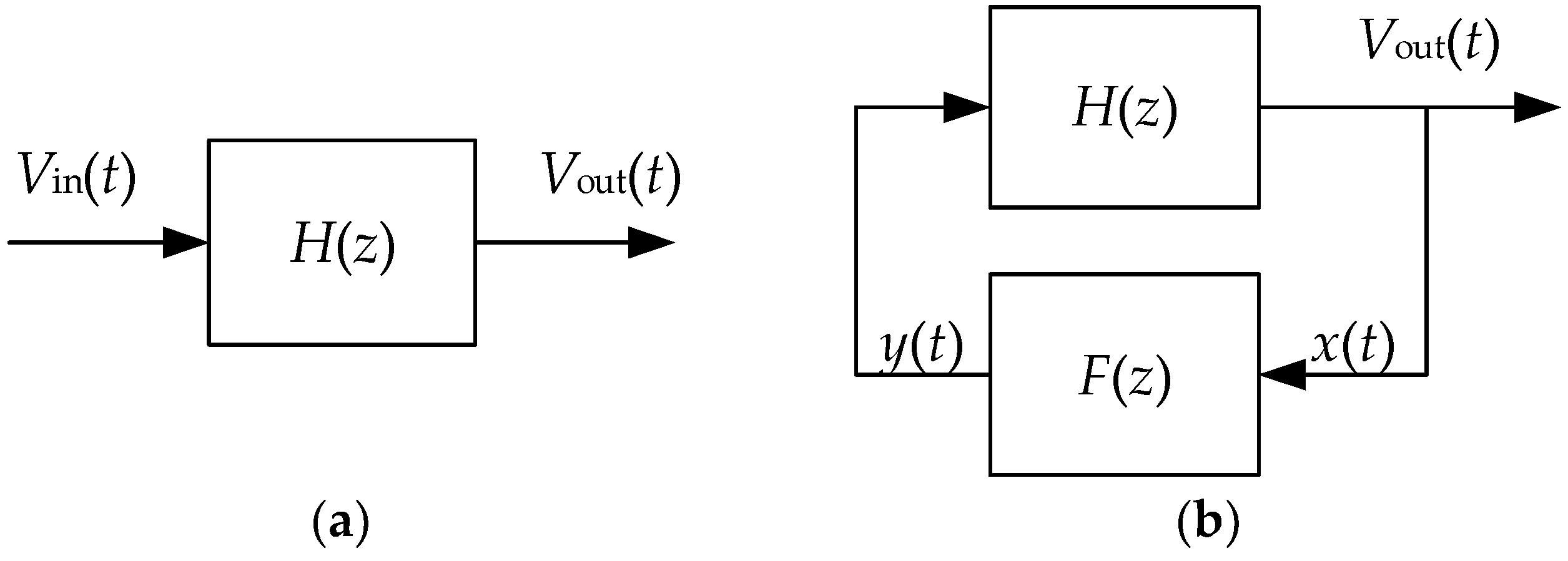
The oscillation-based BIST method is based on splitting complex mixed signal or analog circuit into smaller functional blocks—operational amplifier, comparator, phase detector, Schmitt trigger, first or second-order filter [
5,
15,
16,
17]. Then, the functional block (
Figure 1a) is converted into a robust oscillator by connecting additional feedback circuit, as shown in
Figure 1b [
18]. Oscillation based test system separates operation of functional blocks into two modes—operational and test. During operational mode, the functional block operates as it is designed, while during the test mode, both the input and output of the functional block are disconnected from the main circuit and the corresponding feedback circuit is connected [
19]. The oscillation frequency
fosc of the CUT can be expressed as a function of its components [
5,
20,
21,
22]. In the case of BIST, for functional blocks, which are designed to oscillate, such as Schmitt, voltage or digital controlled oscillators [
23], additional circuitry for tests is not needed.
During test mode, any catastrophic faults, such as opens and shorts, or parametric faults, such as variations of component parameters due to CMOS process variations affect
fosc. In case of catastrophic faults, the oscillation frequency most commonly varies in a wide range, or the circuit does not oscillate at all and such behavior can be detected easily [
20,
24,
25]. In case of parametric faults, the oscillation frequency varies in a narrow range, thus detectability of such faults is limited by the fault estimation system and variations of test-enabling circuit. For such situations, assisted OBIST systems with current measurement block can be used [
26].
A fault detectability is defined as the sensitivity of oscillation frequency to variations of the component. To increase the detectability of catastrophic faults, the sensitivity of CUT oscillation frequency could be increased by manipulating one of component’s value [
10,
12]. Manipulations of parameters in CUT means change of the initial circuit of the tested device, which can lead to non-guaranteed reliability of test results for the designed parameters. The more practical way to increase detectability of faults is to use suitable variation-tolerant fault detection system, which should be versatile for use with different CUTs. Moreover, such systems are suitable for easy implementation in different CMOS technology nodes. It is also possible to derive more than one oscillator from same CUT (e.g., by using more than one feedback circuit) to increase fault coverage if a fault exists in the feedback circuitry [
5].
The main approach for converting active analog filters to oscillators is to position poles in imaginary axis of s-plane. One way to maintain stable oscillations at the output of the filter is to make the quality factor of the filter high enough by disconnecting corresponding component of the filter, which is used to define quality factor of the filter but does not affect other parameters—frequency and gain of the tested filter. The main drawback of such approach is that it does not cover all possible faults of the circuit—quality factor defining component is not tested, which can lead to a false positive outcome of the test procedure. Moreover, not all filter structures are suitable for independent change of the quality factor by using only one component.
Another way of maintaining oscillations at the output of the filter, as was described earlier, is to add a feedback circuit between the input and the output of the CUT. The feedback circuit is designed according to different types of filters [
10]. For the low-pass filters, a positive feedback circuit is needed, which could be implemented with a high-gain inverter, zero-crossing detector, comparator or Schmitt trigger [
5,
27]. Moreover, adequate switches for connecting the feedback circuit are required for proper connection of the feedback circuit during test mode and isolation during filter normal operation [
11]. The transfer function of a filter with feedback can be expressed as follows:
Hfilter(
s)—transfer function of the low-pass filter,
Hfb(
s)—transfer function of the feedback circuit. Oscillation frequency can be obtained from Equation (2):
From Equation (2) it is seen that for the filter to oscillate, a signal must pass the circuit without any attenuation or phase shift. The phase shift is selected according to the required feedback circuit—for the positive feedback, the phase shift should be 0°, while for the negative feedback it should be 180°. This condition is known as a Barkhausen criterion [
5].
3. Oscillation-Based Built-in Self-Test Procedure
In our study, second-order Sallen-Key, Akerberg-Mossberg and Tow-Thomas biquad low-pass filters were used as CUT. The feedback circuit was implemented by using transmission gates and an inverter.
Figure 2 shows a block diagram of the used CUT with a control and an estimation logic block. During the normal operation mode, the feedback circuit is disconnected from the CUT by using the transmission gates and the CUT nodes are connected to the main system. During the test mode, the CUT nodes are disconnected from the main system and the transmission gates are switched into open state, thus connecting the feedback element between the input and the output of the filter. It needs to be mentioned that transmission gates add resistance and capacitance to the feedback circuit, which affect the CUT oscillation frequency and must be optimized in regards to resistance and capacitance of transistor channel, as well as overall chip area.
As a reference clock for the OBIST system, either an internal Schmitt trigger or external reference oscillator, such as PLL or off-chip oscillator, can be used. A Schmitt internal reference oscillator is mainly used in case of detecting catastrophic faults because its oscillation frequency depends on variations of passive components, which are both used in CUT and reference oscillator [
28]. The main drawback of the usage of the internal reference oscillator is a limited usability in detection of parametric faults, since the oscillation frequency of both the CUT and the reference oscillator varies and the probability of a false-positive result increases. In case of the external reference clock, the limits of the parametric fault tolerance are decreased since the reference oscillator is not affected by the component variations and the estimation of errors in the CUT mainly depend only on variations of the feedback circuit and the estimation block.
As an estimation block, a counter and a double digital comparator is used. The bit-count of the counter and the comparator depends on the required test accuracy [
3], but is also restrained due to the error of the oscillation frequency, which depends on the used feedback circuit [
11]. This estimation error (i.e., error of the oscillation frequency due to the feedback circuit) can be determined using a Monte Carlo analysis for each OBIST system. The value of the worst-case scenario is used to predefine an initial estimation error of the CUT oscillation frequency. The
n and
k bit-count of the digital blocks are calculated as per Equations (3) and (4):
n—the bit-count of the digital blocks,
fmax—the maximal CUT oscillation frequency,
fosc—the nominal CUT oscillation frequency, Δ
f—the error of the CUT oscillation frequency,
fref—reference frequency.
The test time of CUT, as well as the overall OBIST system test time are calculated as per Equations (5), (6) and (7):
ttest_CUT—time of the CUT test,
ttest—overall time required for the OBIST system.
The operation algorithm of the proposed OBIST system is presented in
Figure 3.
The proposed OBIST system works as follows. First, using digital code plow and phigh, a predefined counter tolerance range is set in the dual digital comparator. Next, the oscillation process of the CUT is started and 64 periods of the reference frequency signal are counted in order for oscillation in the CUT to settle. Next, the pulse detector detects whether there are oscillations in CUT. If there are not any detectable oscillations of the CUT, the estimation block sets the logic level of the output dcatastrophic to high. In case oscillations of the CUT are detected, the n-bit counter counts pulses for a defined time, which is calculated using Equation (5). The total operating (testing) time of the OBIST system is defined by signal pcnt, which notes the required number of reference frequency signal pulses pref and compares it—if pcnt < pref, dref signal is set to 1, which means the end of the CUT test routine. After the test operation, the counted CUT pulses are compared to the predefined limits and the estimation block produces one of the following test results. If the number of the counted CUT pulses is less than the lower limit plow, or more than the higher limit phigh, the estimation block sets the value of the output dparametric to the low logic level. In another case, if the value of the counted CUT pulses is between the lower and the upper limits, the estimation block sets the output to the high logic level. Such estimation block provides simple yet informative result of the CUT test.
It should be mentioned, that predefined test limits for the oscillation frequency estimation are set for each CUT individually, depending on the requirements for the intended application [
29]. For example, requirements are lower for a gain or phase, as well as cut-off frequency (which all depend on variations of CMOS technology) of the filter for applications in LTE or IEEE 802.11g transceiver with a 16QAM modulation scheme [
30]. Therefore, wider test limits can be set, if such filter is used as a CUT. In another case, when the CUT is a filter used in transceivers, which are running LTE-Advanced, WiMAX and most recent IEEE 802.11ac and ax data transmission standards, where modulation codes from 64QAM up to 1024QAM are used, more strict requirements are set and the narrower test limits should be accordingly defined [
31]. In general, there is a trade-off between requirements for the filter per compliance to the data transmission standard and a yield of the of fault-free CUTs.
A dstart input of the control block is used to start the CUT testing procedure. It can be controlled by an external or internal chip controller. The same controller can be used for the testing of several CUTs, gathering and estimating the test results. A dtest output signal is used to control transmission gates and as a flag for other circuits, such as a digital signal processor of the transceiver, whose filter is used as CUT and since its operation is changed from the normal mode to the test mode, transceiver’s data transmission should be stopped. After dtest signal is set to high logic level, the control block identifies if oscillation in CUT is started. In case of high logic level in the output of pulse detector, both counters in the control block and the estimation block are started and the routine for the estimation of error is used. In a case when oscillation in the CUT does not start during the defined time, the test result corresponding to a catastrophic fault is set, which points to existing shorts or opens in the CUT and it cannot be used for its main operation.
4. Simulation Results
The simulation results of the proposed OBIST system for analog active filters were carried out in 0.18 µm CMOS technology using Cadence Virtuoso IC design software. Transient and Monte Carlo simulations were used to investigate proposed self-test system and CUT. Simulations were carried out using typical operation conditions: temperature was set to 27 °C, supply voltage was set to 1.8 V, typical models of the transistors were used. As a CUT, LPF of various structures were designed and investigated, namely Sallen-Key, Akerberg-Mossberg and Tow-Thomas biquad filters, since these structures are used in modern wireless transceivers and their BIST test results differ based on the transfer function and sensitivity to the variations of the components. Schematics of Sallen-Key, Akerberg-Mossberg and Tow-Thomas filters, including used feedback circuits, are presented respectively in
Figure 4,
Figure 5 and
Figure 6. Transfer functions for used filters are presented respectively in Equations (8), (9) and (10) [
32]. The operation amplifier used for testing of OBIST system was a conventional two-stage amplifier with a Miller compensation circuit and its schematic is presented in
Figure 7. The schematic of the used feedback circuit, consisting of the transmission gates and the inverter is presented in
Figure 8.
HSK(
s)—transfer function of second-order Sallen-Key LPF,
HAM(
s)—transfer function of second-order Akerberg-Mossberg LPF,
HTT(
s)—transfer function of second-order Tow-Thomas LPF,
C1,
C2,
R1-
R6—the capacitances and resistances of capacitors and resistors C1, C2, R1-R6 of each filter, presented in
Figure 4,
Figure 5 and
Figure 6.
4.1. Influence of Testing Hardware
For the proper use of the OBIST strategy on a CUT, it is necessary to determine the influence of the testing hardware, namely the feedback circuit, on the oscillation frequency of the CUT and the undetectable range of parametric faults. In the proposed OBIST system for use with LPF, a feedback circuit is composed of a high gain inverter and transmission gates. The main parameters to be analyzed are dependency of the resistance of the transmission gates on the size of the transistor; dependency of the CUT’s oscillation frequency on the size of the transmission gates; dependency of the CUT’s oscillation frequency on the size of the inverter. In addition, the influence of the size of the inverter on variations of CUT’s oscillation frequency based on variations of the CMOS process was analyzed. For all tests, the length of NMOS and PMOS transistor channels was fixed L = 180 nm, while the width of NMOS and PMOS channels was WNMOS = 250 nm, WPMOS = 500 nm. The size of the transistors was changed by adding additional gate fingers and are described as M.
The transmission gates consisted of NMOS and PMOS transistors as well as an internal inverter for the control of transmission gate.
Figure 9 shows the dependency of the resistance of the transmission gate on the transistors’ size. It is seen, that when size of the transistors was a minimum (
M = 1), the resistance of the transmission gate was 7.86 kΩ. If size of the transistors was
M = 100, the resistance decreased to 80 Ω. It also should be mentioned that when the size of the transistors increased above
M = 20, the resistance of the transmission gate was not significantly affected.
Figure 10 shows the dependency of the CUT’s oscillation frequency on the transistor’s size of transmission gate and inverter in the case of Sallen-Key (
Figure 10a), Akerberg-Mossberg (
Figure 10b) and Tow-Thomas (
Figure 10c) filters. It can be seen, in the case of Sallen-Key LPF, when the size of the inverter was minimal (
MIV = 1) and the size of the transmission gates was
MTG = 18, CUT’s oscillation frequency was at a minimum and equal to 18.27 MHz, while the maximum oscillation frequency was observed when
MIV =
MTG = 100 and was equal to 37.85 MHz. In the case of the Akerberg-Mossberg filter, the minimum oscillation frequency was observed when
MIV = 6,
MTG = 44 and was equal to 26.17 MHz, while in the case of the Tow-Thomas filter, the minimum oscillation frequency was 28.32 MHz when
MIV = 4,
MTG = 76. The maximum oscillation frequency of the Akerberg-Mossberg and Tow-Thomas filters occurred when
MIV = 12,
MTG = 6 and was equal to 28.57 MHz and 27.18 MHz respectively. Further increases of the transmission gate and inverter size decreased the oscillation frequency linearly since the CUT load increased [
33].
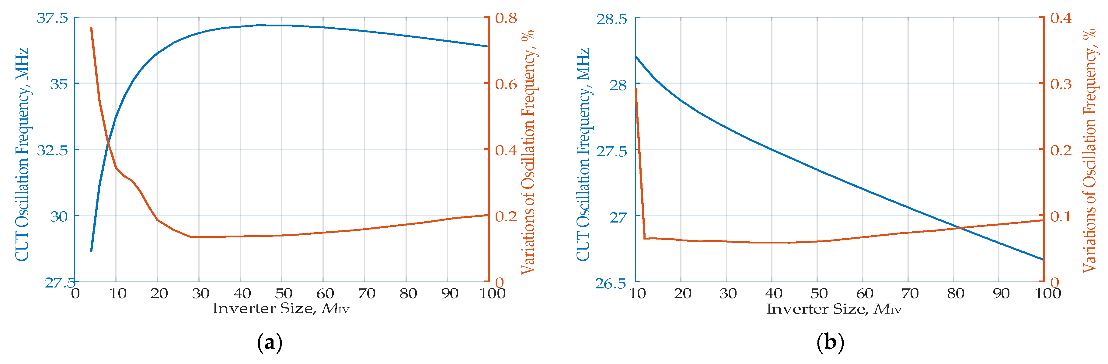
CUT is not the only one affected by CMOS process variations in a way of parametric faults. The feedback circuit of the testing hardware is also affected. The most important parameter of the feedback circuit of testing hardware, which needs to be estimated, is the variations of CUT’s oscillation frequency in regard to the variations of size of the feedback inverter. It can be done by using Monte Carlo and corner condition analyses. The number of iterations of the Monte Carlo analysis was set to 1000 for evaluation of the oscillation frequency and it varied by changing the size of both transmission gates and inverter in the feedback circuit.
Figure 11 shows CUT’s oscillation frequency and variations of the oscillation frequency using different sized inverters, when the size of the transmission gate was
MTG = 16. Monte Carlo simulations were repeated by changing the size of the feedback inverter from
MIV = 4 (in the case of the Sallen-Key filter) or
MIV = 10 (in the case of the Akerberg-Mossberg and Tow-Thomas filters) to
MIV = 100. It can be seen that the variations of the oscillation frequency were lowest when the size of the inverter was
MIV = 28—it ranged from 0.08% in the case of Akerberg-Mossberg (
Figure 11b) and Tow-Thomas (
Figure 11c) LPF to 0.13% in the case of Sallen-Key (
Figure 11a) LPF.
Figure 12 shows CUT’s oscillation frequency and variations of the oscillation frequency using different sizes of the transmission gate, when the size of inverter was
MIV = 28. Monte Carlo simulations were repeated by changing the size of the feedback inverter from
MTG = 2 to
MTG = 100. It can be seen that the variations of oscillation frequency were lowest when the size of the transmission gates was
MTG = 16—it ranged from 0.08% in the case of Akerberg-Mossberg (
Figure 12b) and Tow-Thomas (
Figure 12c) LPF to 0.13% in the case of Sallen-Key (
Figure 12a) LPF. Further increases to the size of the inverter or transmission gate did not reduce the variations of the CUT’s oscillation frequency. Thus, the size of the inverter equal to
MIV = 28 and the size of the transmission gate equal to
MTG = 16 was the optimum point in regard to used chip area and frequency variations.
Likewise, every structure of LPF was investigated for variations in the oscillation frequency due to the imperfections in the feedback transmission gates and the inverter and the results of Monte Carlo analysis are presented in
Figure 13 and summarized in
Table 1.
4.2. Fault Coverage of Catastrophic Faults
The proposed OBIST system was used to estimate catastrophic faults in the CUT. As catastrophic faults in the CUT short and small-value resistance and open circuits in both the operational amplifiers and the top level of the CUT were inserted. As the short and small-value resistance circuits, 10 Ω, 100 Ω and 1000 Ω resistors were connected between the terminals of the transistors or in parallel between the capacitors and resistors [
8]. Moreover, a real case scenario was simulated, where shorts were injected only between the same components’ terminals. As open circuits, a 10 MΩ resistor was connected in series to every terminal in the CUT, while for the gates of the transistors of the operational amplifier, a floating node connection was simulated. The configuration for catastrophic fault injection is presented in
Figure 14. Catastrophic faults in such connections depict real-case situations in the produced CMOS chip with faults.
Transient simulations were carried out to investigate catastrophic fault coverage for all three tested LPF structures and are presented in
Table 2. It should be noted that both output signals of the estimation block, namely
dcatastrophic and
dparametric should be checked for estimation of catastrophic fault coverage as in some cases of catastrophic fault injection, slight variation of oscillation frequency was detected. Thus, such a fault was identified as parametric.
It is seen from
Table 2 that catastrophic fault coverage of the CUT was higher than 96% for every LPF structure. When Sallen-Key LPF was used, the best coverage of the catastrophic faults was achieved in the case of testing for short faults when 10 Ω and 100 Ω shorts were injected. A fault coverage of 97% was observed in the case of detection of 1 kΩ short faults and open faults, where only one fault was non-detectable. When Akerberg-Mossberg and Tow-Thomas LPF were used, all open faults were detected. In the case of short faults, similar results were observed for both filters except in case of a short 1 kΩ fault injection when the Akerberg-Mossberg filter was used, where two faults were not detected. It should be noted that total number of injected faults in the used filters differed since the Sallen-Key filter used less components, both passive and active.
4.3. Fault Coverage of Parametric Faults
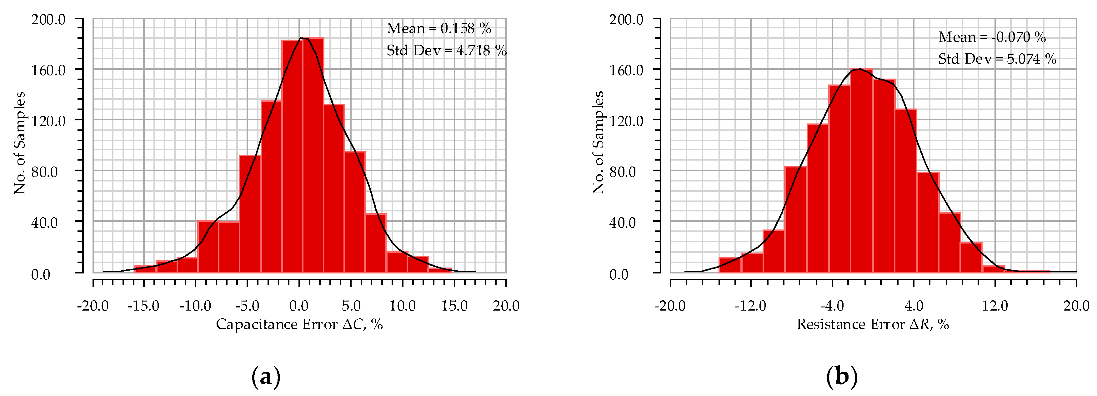
Transient and Monte Carlo simulations were carried out to investigate parametric fault coverage of the proposed OBIST system. As parametric faults, variations of every passive component in CUT were simulated. Limits of variations of real components were estimate using Monte Carlo simulations since such CMOS production data are often not available for public use. The results of Monte Carlo analysis for estimation of possible variations of the used resistors and capacitors are presented in
Figure 15. It is seen that the variations of capacitance can reach up to ±16% (
Figure 15a), while the variations of resistance reached ±17% (
Figure 15b), Thus, the maximum possible ±20% parametric fault injection in the top level of the used CUTs was simulated [
34]. It should be noted that the top level of CUT was considered as a top view of the LPF schematics with passive components and operational amplifiers as presented in
Figure 4,
Figure 5 and
Figure 6.
The undetectable limits of the component variations for each passive component in different structures of LPF are presented in
Table 3. It is seen that the oscillation frequency of the Sallen-Key LPF (
Figure 4) varied in a wider range and reached up to −13.95% – 17.90%, however its range of undetectable limits was the narrowest and did not exceed −0.74% – 0.72% for resistor R2 and was as low as −0.17% – 0.16% for capacitor C2. The Akerberg-Mossberg LPF (
Figure 5) showed the widest range of undetectable limits for resistor R4, reaching −3.31% – 1.00%, while the narrowest undetectable range was for capacitor C1 with limits from −0.21% to 0.08%. The last used LPF structure, namely Tow-Thomas (
Figure 6), shows intermediate results on undetectable limits, as for resistor R1 it did not exceed −2.39% –1.44% and the limits were the narrowest for resistor R2, ranging from −0.11% to 0.25%.
In terms of the main LPF parameters, namely cut-off frequency and output gain, the maximum calculated undetectable deviation respectively was Δ
fc = 0.5% and Δ
A = 0.1% for the Sallen-Key filter and it is suitable for use with most modern data transmission standards IEEE 802.11ac and ax with 256 QAM and higher modulation schemes [
31]. In the case of Akerberg-Mossberg LPF, the maximum deviations were Δ
fc = 2.1% and Δ
A = 2.1%, while in the case of Tow-Thomas LPF, maximum deviations of Δ
fc = 0.7% and Δ
A = 0.7% were observed, thus, enabling its usage with most data transmission standards up to IEEE 802.11ac and ax with the 256 QAM modulation scheme [
31]. Estimation of the tested LPF usability with data transmission standards is in regard to error vector magnitude [
30].
Small ranges of undetectable faults were reached by using a high resolution counter and a double comparator for estimation of CUT’s oscillation frequency. In addition, a feedback circuit of the used OBIST system was tolerant to CMOS processed and mismatch variations. It needs to be mentioned that other studies used capacitor tuning to change the oscillation frequency of the OBIST system, thus, increasing the range of catastrophic fault coverage [
12].
Figure 16 shows the variations of the oscillation frequency of a second-order Sallen-Key LPF by changing the value of every passive component in range of –20% to +20%. Similar analyses were performed for Akerberg-Mossberg and Tow-Thomas LPF and
Table 3 shows a summary of the parametric fault detection for every LPF used as a CUT.
Table 4 shows the performance of the proposed OBIST system compared with other reported OBIST systems. The table shows that most commonly the second-order Sallen-Key LPF is used as a CUT.
The proposed OBIST system occupied 0.0096 mm
2 of chip area in a 0.18 µm CMOS technology node. For OBIST system verification, low-pass filters with conventional operational amplifiers were used. The area overhead of the proposed OBIST system for second-order Sallen-Key filter was +160%, and for the Akerberg-Mossberg and Tow-Thomas filters it was +96%. It should be mentioned that real filters, which are used in production, usually occupy a larger area of silicon [
17]. In Reference [
17], the second-order filter occupied 0.06 mm
2 of chip area [
17], thus, the OBIST system area overhead was +16%. The power overhead of the OBIST system for the second-order Sallen-Key filter was +48%, for Akerberg-Mossberg it was +45% and for the Tow-Thomas filters it was +46%, but since the OBIST system usually is used only once, there is no power consumption overhead in the regular operation of the CUT.
5. Discussion
Self-testing systems have limited implementation ability in VLSI circuits due to the large number of circuits to be tested and the limited free chip area for the test systems. Some works present OBIST systems implemented using discrete components and the impact of switches in the feedback circuit has been investigated [
5,
6]. Another approach of the OBIST system is to compare a fault-free circuit to a faulty circuit, and the difference of the counted pulses can be estimated, highlighting the level of parametric faults in the CUT [
9]. Similarly to the OBIST system presented in Reference [
9], a phase shift between fault-free and faulty circuits could be estimated [
35]. In the case of catastrophic fault detection, an on-chip Schmitt oscillator could be used as a reference signal for counting CUT pulses, but such approach cannot be used for the detection of parametric faults [
28].
Most research on OBIST has been focused on different techniques for transforming different CUTs into oscillators, finding optimal oscillation frequencies for wide catastrophic fault coverage or using on-chip reference signal sources as a test signal. However, precise detectability of parametric faults in CMOS technology has not been sufficiently investigated. Moreover, most of the related works use only the Sallen-Key LPF structure as the CUT, thus, the OBIST structures have not been tested with other LPF structures, which are more common in modern wireless transceivers.
From the performed analysis of the proposed OBIST system, where variations of the oscillation frequency of the CUT have been investigated, it could be concluded that undetectable limits of parametric faults can be decreased by designing variation-tolerant feedback circuits. Variations in the feedback circuit increase the range of the oscillation frequency, where parametric faults of the CUT could not be estimated, since the fault could be present in both the feedback circuit or the CUT. The high gain inverter was used as a feedback circuit, thus, due to the small number of components, the impact of the CMOS processed and mismatch variations were at a minimum, as compared to other feedback circuits. Moreover, simulations of transistor sizing in the feedback circuit show the minimum and maximum oscillation frequency and its variations; thus, the optimal size of transistors were chosen.
Catastrophic fault coverage could be increased by using an internal reference frequency oscillator, however such systems lack precise parametric fault coverage. It is possible to maintain both reference frequency sources in an OBIST system for two-step testing of a CUT, but the test time accordingly increases. Another approach to increase catastrophic fault coverage is to increase the oscillation frequency [
12], but there is a need to change the value of the component with a high sensitivity to oscillation frequency, which outcomes in testing of modified CUT. Thus, the test results cannot be covered for a non-modified circuit.
The proposed OBIST system used an external reference oscillator as a system clock generator. Moreover, two-step testing of the chip was performed for the estimation of catastrophic and parametric faults. The sizes of the transmission gates and inverter in the feedback circuit were selected for optimal point in regard to the variations of the CUT oscillation frequency and the used chip area. The range of the parametric faults was changeable in regards to the required low-pass filter accuracy. The estimation block provided information on the detection of any catastrophic or parametric faults, which can be transmitted to the controlling device, such as a microcontroller.
In the case of parametric faults in a CUT, self-tuning systems can be used to compensate these faults [
36,
37,
38,
39]. Such systems can tune desired parameters of filters: cut-off frequency, gain, or the quality factor. Such self-tuning systems were used when a high yield of fault-free integrated circuits was needed, but the area overhead for the tuning components was directly dependent on the desired tuning accuracy.
Finally, further improvement of OBIST system could be achieved through the evaluation of the CUT source current and the amplitude of oscillations. However, such tests require analog circuitry, in particular analog to digital converters, which are chip area and power demanding in comparison to mostly digital fault estimation and control blocks, which is presented in current work.
6. Conclusions
A novel oscillation-based built-in self-test system with fault estimation circuit was designed and investigated. Attention has been paid for precise estimation of both catastrophic and parametric faults in the circuit under test. As the circuits under test, three structures of low-pass filters were designed and investigated, namely Sallen-Key, Akerberg-Mossberg and Tow-Thomas. It can be seen that test results for these low pass filters varied since sensitivity to the oscillation frequency in regard to the passive components differed. The Sallen-Key second-order low pass filter had the narrowest undetectable range of the parametric faults and it did not exceed –0.74% – 0.72% of the passive components’ nominal value. The cut-off frequency error and gain error of this filter were Δfc = 0.6% and ΔA = 0.2% respectively. On the other hand, the widest undetectable range of parametric faults was observed in the Akerberg-Mossberg low pass filter, reaching up to –3.31% – 1.00%. Its cut-off frequency error and gain error were Δfc = 2.1% and ΔA = 2.1% respectively. The catastrophic fault coverage for all low pass filter structures was higher than 97%.
The estimation and control blocks of the designed system can easily be implemented in different CMOS technology nodes, as most components are digital. The estimation block was versatile and could be reconfigured according to the requirements for the targeted application. It needs to be mentioned that precise fault estimation is not always needed since different requirements are set for filters in transceivers. Thus, compromise should be met in regards to the target yield for the produced chips, requirements for hardware as per the used wireless data transmission standard and overall chip area for the self-test system.


