Article

Smartphone-Based Context Flow Recognition for Outdoor Parking System with Machine Learning Approaches

1
Faculty of Information Science and Technology, Multimedia University, 75450 Melaka, Malaysia
2
Faculty of Engineering and Technology, Multimedia University, 75450 Melaka, Malaysia
*
Authors to whom correspondence should be addressed.
Electronics 2019, 8(7), 784; https://doi.org/10.3390/electronics8070784
Submission received: 18 April 2019 / Revised: 22 May 2019 / Accepted: 11 June 2019 / Published: 13 July 2019
(This article belongs to the Section Artificial Intelligence)

Abstract

:
Outdoor parking systems are one of the most crucial needs in a smart city to find vacant parking spaces in outdoor environments, such as roadsides, university campuses, and so on. In a typical outdoor parking system, the detection of a vehicle entering and leaving the parking zone is a major step. At present, there are numerous external sensor-based and camera-based parking systems available to detect the entrance and leaving of vehicles. Camera-based parking systems rely on sophisticated camera set-ups, while sensor-based parking systems require the installation of sensors at the parking spots or vehicles’ sides. Due to such complication, the deployment and maintenance costs of the existing parking systems are very high. Furthermore, the need for additional hardware and network capacity increases the cost and complexity, which makes it difficult to use for large deployment. This paper proposes an approach for outdoor parking utilizing only smartphone integrated sensors that do not require manpower support nor additional sensor installation. The proposed algorithm first receives sensor signals from the driver’s phone, performs pre-processing to recognize the context of drivers, which is followed by context flow recognition. The final result is obtained from context flow recognition which provides the output of whether the driver is parking or unparking. The proposed approach is validated with a set of comprehensive experiments. The performance of the proposed method is favorable as it uses only the smartphone’s internal sensors to recognize whether the cars are entering or leaving the parking area.

1. Introduction

A smart outdoor parking system (SOPS) is a smart city technology that comforts drivers to find vacant parking spots and delivers that information to drivers or parking management through the Internet or private network. SOPS is a burning need for planning the smart city to eliminate driver’s frustration for searching for parking spots. It is renowned as one of the most significant means for the encroachment of urban infrastructure. In large cities, the parking problem has been a major daily issue. A study has shown that 30% of the road traffic is produced by vehicles touring for a vacant parking spot [1]. According to a study by [2], it has been seen that crowded streets in the US cost $78 billion yearly in the form of $4.2 billion and $2.9 billion for wasting time and gas, respectively. White, P.S. [3] has also shown that, in New York City, 45% of the traffic generated from the automobile circulation for searching for parking spots cause several problems, such as traffic congestion, air pollution, and wasted energy. According to a study by [4], in the US nearly 42% of people miss their appointments due to the circulation for parking, another 34% abandoned their trips by being frustrated from parking issues and, in New York, a driver has to waste 107 h annually for searching for a parking spot. Although there are various types of smart parking solutions available, those existing solutions are not suitable for large area coverage due to high installation and maintenance costs. The existing systems are expensive because of the nature of their implementation. The reasons why the existing systems fail to be inexpensive is explained in Figure 1.
Usually, a smart parking ecosystem consists of two flows, namely, the flow of information, as shown in the upper triangle of Figure 1, and the flow of vehicles, as shown in the lower triangle in Figure 1. The red line in Figure 1 separates the two parking flows.
Firstly, vehicle flow is responsible for detecting the entrance or leaving of the vehicles. Vehicle flow occurs when the drivers are on their way to look for the parking spaces (Figure 1A). The drivers receive necessary parking information from the server (Figure 1D) through information dissemination systems, such as base transceiver stations (BTS) (Figure 1C), and drive to the parking area (Figure 1B) to park their vehicles. Secondly, information flow is responsible for broadcasting the parking availability information to the other drivers who are looking for a parking space. Information flow comprises of parking information starting from the moment the automobiles are detected by the cameras or sensors and ends with the delivery of this information to the drivers. Once a car departs from or arrives at a parking area, the information of parking availability of that parking zone is updated to the servers and the servers distribute the information using BTS, roadside infrastructure (RSI), or variable message signs (VMS) to other drivers who are searching for an available parking place near that parking zone. The system sends the updated information to the storage devices or clouds from where the drivers can retrieve information through BTS, RSI, or VMS.
This research focuses on the first step (detection of vehicle’s entrance and leaving) of the parking ecosystem as shown with a rectangular box in Figure 1. To detect whether a car is leaving or entering the parking spot, cameras are utilized in most of the existing solutions [5]. The works in [6,7] state that the parking events are detected by installing sensors under parking spaces, tethering sensors with vehicles, or using sophisticated cameras in the existing parking systems. To cover a large parking area, it requires many cameras or sensors. For example, Nice, a city in France, has implemented a parking project that has 10,000 external sensors in 13 different car parking zones and the estimated deployment cost of the system is $15 million euros [7]. Due to the cost of buying these external sensors, it makes the existing system very expensive. Los Angeles, another popular example, deployed smart parking solutions with external sensors. To implement the same system in another place it requires many things to be considered, such as the inhabitant’s habits, and the street layout needs to be tested to adapt a suitable technology [7]. Additionally, a largeinitial investment is also required. For example, [8] has indicated that the cost per sensor per month for monitoring in San Francisco for a single parking space is beyond $20. Thus, it is difficult to buy many cameras or sensors to support such a demand in practice. Therefore, outdoor parking systems designed with external sensors in most cases cannot be implemented at large scale due to high implementation and maintenance cost. Furthermore, cameras and sensors do not work well in some situations, such as during foggy or raining seasons. Cameras do not give good accuracy, as temperature changes and air conditions affect performance [9].
Even though some smartphone-based solutions, such as OpenSpot, Roadify, Primsopt, and SpotScout were deployed in the past few years, these solutions required drivers to manually input information into the system when they are leaving their parking spots [10]. This manual input causes inconvenience to the drivers. Thus, a cost-effective solution is needed to automatically detect whether a driver is entering or leaving the parking area, which would be beneficial to both the drivers and parking management.
Nowadays, smartphone internal sensors play a significant role in commercialization and real-time applications, such as indoor navigation and physical activity detection [9,10,11,12]. These built-in smartphone sensors could be deployed to replace external sensors for parking recognition. Therefore, this paper presents an approach to detect a parking or unparking event (either entering or leaving the parking place) using smartphone sensors. The proposed method represents a low-cost solution as compared to camera- or external sensor-based parking systems. The information flow process, as shown in the Figure 1, is beyond the scope of this work.
The contribution of this paper is the development of a driver’s context flow recognition (CFR) approach to detect parking activities using smartphone internal sensors. Machine learning methods have been incorporated into CFR to achieve high accuracy rates.
The remainder of the paper is structured as follows: Section 2 presents the related works, Section 3 demonstrates the theoretical ideas of the proposed method, Section 4 illustrates the details of the proposed methodology, Section 5 explains the result and discussion and, lastly, Section 6 completes the paper by commenting on prospective works.

2. Literature Review

The history of smart parking started with the invention of vehicles. In any area where there was significant traffic, there have been noticed parking systems [13]. The earliest automated parking system was built in 1905, which was a semi-automated system [14]. However, the interest of smart parking increased in the United States in the 1940s to 1960s [13]. In the following sub-sections some of the recent parking systems are discussed.

2.1. Vision-Based Parking Systems

Vision-based parking solutions have become smart with fast growth in the era of computer vision and image processing [15]. The core idea of vision-based parking is to exploit the technique of computer vision and image processing to investigate video streams of CCTV [15]. It examines the pictures taken by the cameras to identify and discover the unfilled parking slot. Reference [16] proposed a vision-based algorithm, using a deep convolutional neural network that took consideration of surrounding images as the input. A wide-angle camera was utilized to cover the whole parking area in the proposed method by [17], in which anyone without any technical background could setup the system easily.

2.2. Sensor-Based Parking Systems

In [18], an available parking lot tracking and detection solution that fused ultrasonic and around view monitor (AVM) sensors is suggested. The system has three stages, which include parking lot marking, parking lot occupancy classification, and parking slot track. Scanning laser radar is used by [19] to recognize free parking spaces between vehicles. This suggested method comprises data processing, corner detection and, lastly, parking position detection. Moreover, a solution to observe the entrance and leaving of cars for outdoor parking areas was suggested in [20]. Reference [21] presented a similar approach that employed radio frequency and infrared sensors for communication.

2.3. Smartphone-Based Parking Systems

In the last few years, mobile phones experienced a significant high-tech development with the combination of innovative hardware and implanted sensors that were being used to solve many real-world problems. A new approach, called probabilistic internal navigation (ProbIN) [22], that utilizes a Bayesian probabilistic framework, was deployed to recover genuine motion from noisy sensor readings. It was an innovative statistical method for recording minimal-cost inner sensors to obtain the user’s location. Reference [23] suggested a phone-based driver tracing system that deliberated the path of the driver. It was presented as a way to sense when a driver is about to exit from a parking place. The approach was built on the internal positioning system (IPS) that was sufficient for mapping users’ movements with short distances. IPS utilizes smartphone sensors, such as accelerometers, gyroscopes, GPS, and digital compasses, to detect parking or unparking. A map-matching and waist-mounted unit was employed to acquire precise estimate results. A different approach was suggested by [23] which had collected the user contextual information, displayed as an approximated distribution of free parking spots using a map. Bluetooth and GPS were used to collect information about users, such as user position, user’s path, and activity performed by users. In order to gather the user path and position it received the coordinates of the users after a regular interval. Reference [23] states that a path consists of a number of coordinates, longitude and latitude, and is shown by Equation (1):
p a t h z = [   ( x 1 ,   y 1 ) ,   ( x 2 ,   y 2 ) , ( x 3 ,   y 3 ) , ,   ( x n ,   y n ) ]
where xn is the nth latitude and yn is the nth longitude of pathz. From the path, [24] builds two arrays to store the latitude and longitude for the user in each interval of movements:
l a t z = [ x 1 ,     x 2 ,   x 3 ,   ,   x n ]
l o n z = [ y 1 ,     y 2 ,   y 3 ,   ,   y n ]
Reference [6] presented Park Sense, to detect whether a driver is back to his car or moving away from the car. To notify parking actions, Park Sense leveraged pervasive Wi-Fi beacons. Reference [6] presented the set of Wi-Fi signatures with the following Equations (4) and (5):
S p =   { s p ( 1 ) , s p ( 2 ) , s p ( 3 ) , s p ( n ) ,   }
W p =   { w p ( 1 ) , w p ( 2 ) , w p ( 3 ) , w p ( n ) ,   }
where sp (i) stands for service set identifier (SSID) and wp (i) stands for the ratio of the beacon, at access point i, and n represents the number of total access points through all scans. Pocket Parker, presented by [24], identifies the driver’s movement using a mobile phone’s accelerometer and GPS. The system stores collected data in a centralized database and broadcasts the information to the drivers using Wi-Fi and the cellular network. Reference [24] used existing activity recognition approaches to detect the arrivals and departures of the drivers.

2.4. Summary of Existing Works

From the above studies it is observed that vision-based techniques are flexible to deploy, and it requires a lower maintenance cost. Furthermore, vision-based parking systems do not involve an intricate configuration. Additionally, empty parking spaces can be recognized exactly by analyzing the parking spot images. However, vision-based systems are not free of disadvantages, such as the tracing solution sometimes providing the wrong result due to obstructions and lighting. The cameras needed to be set up in a place where the whole parking zone can be seen. Very often, it requires a high price for the high-resolution camera [25]. In fact, a miscellany of ground materials, illumination changes, and impulsive shadows make vision-based parking more difficult. Secondly, external sensor-based parking approaches rely on extra sensors and the systems need complex infrastructure, which is problematic to organize. It becomes worse when the entire infrastructure needs to be refurbished. Lastly, the smartphone-based system delivers relaxed placement with no or very low installation and maintenance cost. Since the mobile-based parking system does not need exterior hardwire installation and preservation charge, it has motivated us to carry on the research to develop a smart-sensor based parking system.

3. Theoretical Idea of the Proposed Approach

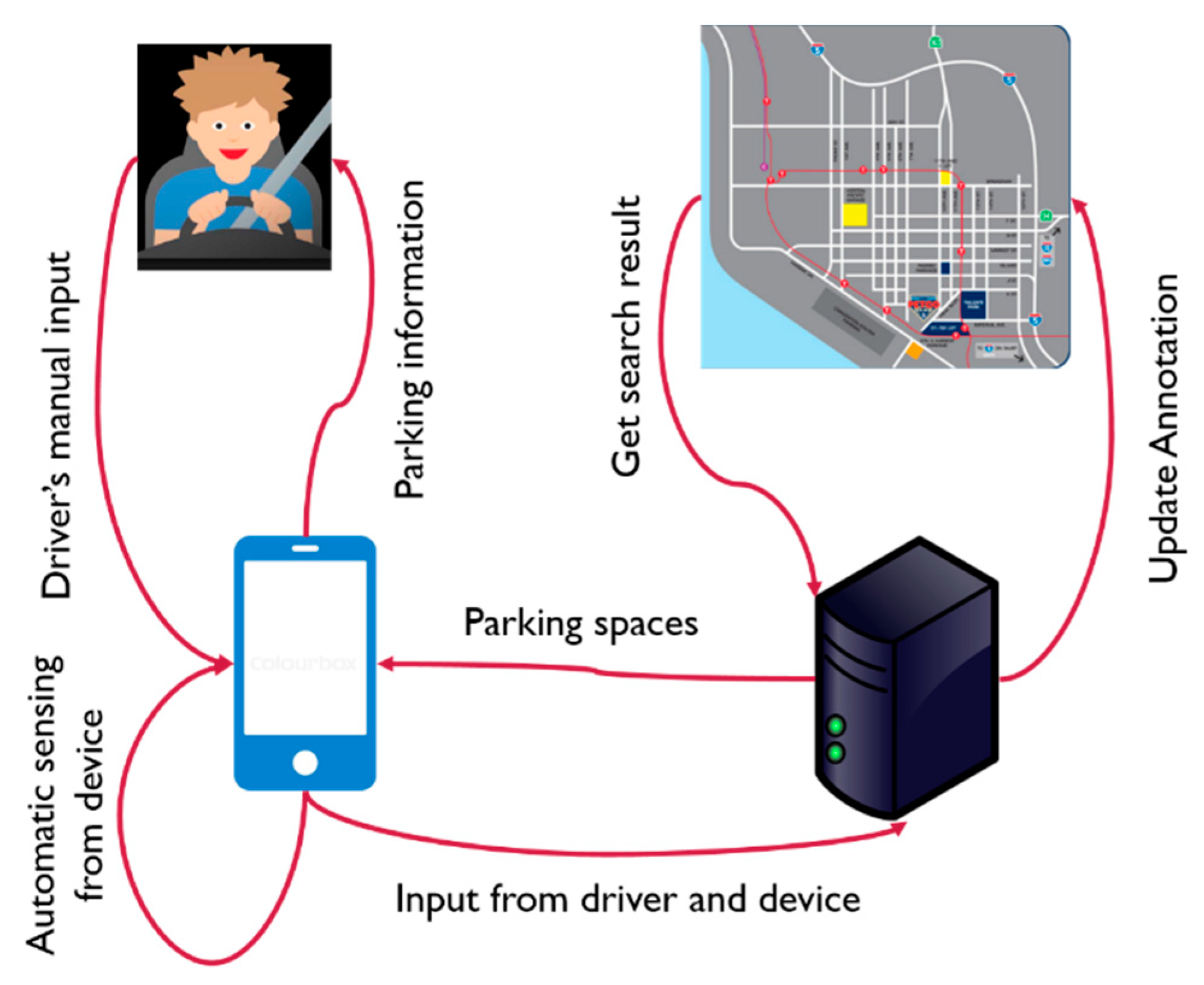
This section illustrates the theoretical idea of the proposed parking system. Generally, in a smartphone-based parking system, there are four main modules which are: driver, driver’s device, server, and parking zones or maps. The server collects data from the driver who reports his/her trip information, like current location, vehicle speed, and destination, either through manual input or through client devices, such as smartphones or tabs while driving. The server uses this information and produces an actively annotated parking accessibility map in real-time. When a driver is near to his/her destination, the server is requested for the live map for potential parking availabilities based on the driver’s current position. Then the server informs client devices of the search result that there might be a nearby parking slot or exact parking spot. The integration of each of the modules is illustrated with a reference model in Figure 2.
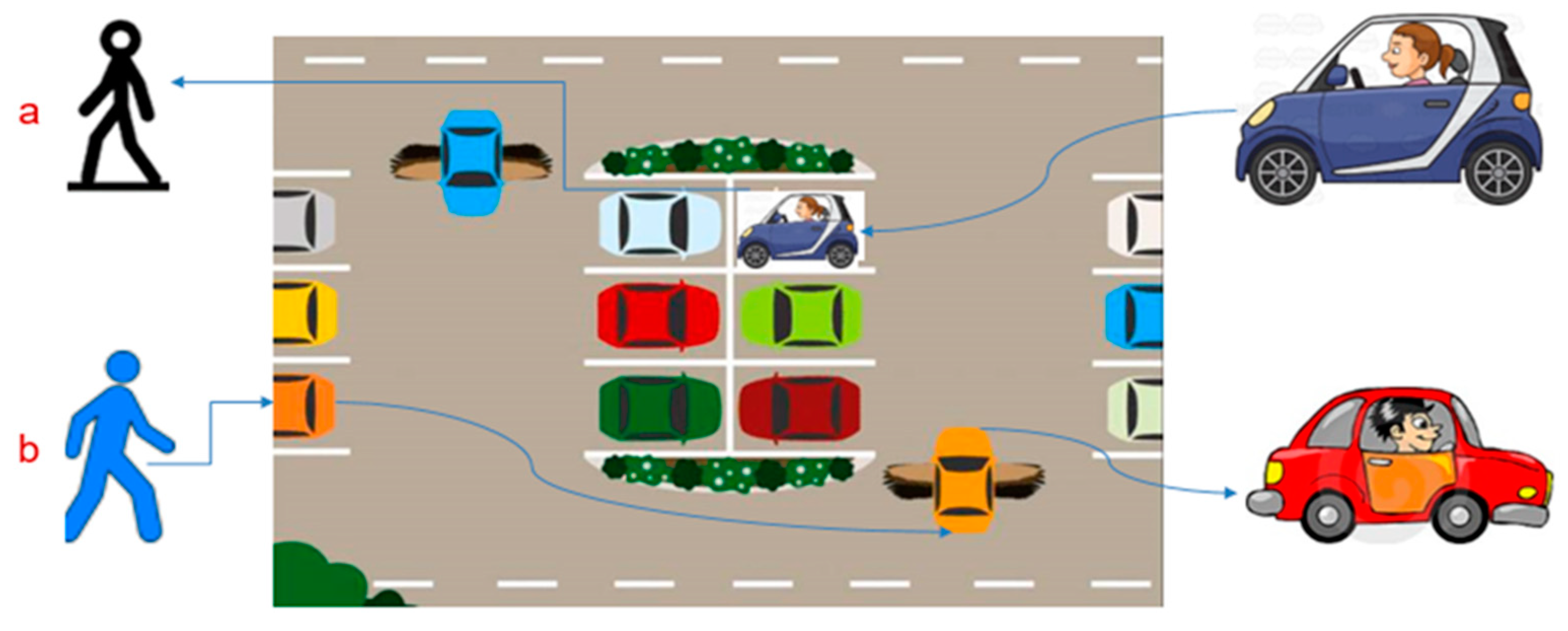
The ultimate goal of this research is to automatically know whether a driver is parking or leaving the parking area. By knowing whether the driver is parking or leaving, it is possible to know the number of available parking spaces in a parking zone at any time. It assumes that the capacity or availability of parking spaces can be updated at any time. To arrive or depart from a parking area, a driver has to perform some sequential actions. For example, to park a vehicle, the driver is required to drive the vehicle to the parking zone and walk toward his/ her destination from parking zone, implying an activity flow of driving → walking. On the other hand, the opposite flow (walking → driving) occurs when the driver leaves the parking zone. The flow that occurs when parking a car is shown in Figure 3a, while Figure 3b shows the flow of leaving a parking space. Thus, by recognizing the contexts of the drivers and the flow of context it is possible to recognize whether a driver is parking a car inside the parking zone or leaving from the parking zone.
The typical activities flow that occurs during a parking or unparking event is shown in the activity theory diagram in Figure 4. Figure 4a shows the possible activity flows that occur while unparking a car (or while leaving from the parking zone). On the other hand, Figure 4b shows the flows that would occur while the drivers enter the parking zone to park the car.
From Figure 4 it is clear that the flow of activity begins with any activities, except driving, and ends with a driving activity during an unparking event. On the other hand, the driver must perform a driving activity first and finishes with either walking or running during a parking event. It is important to detect a full trajectory of the driver’s context to identify a parking or unparking event. In this paper, a full trajectory for a parking event refers to a flow that starts with driving and ends with either walking or running. Similarly, the flow for an unparking event starts with either idle or walking or running activity and ends with driving. Throughout this paper, the term “parking” means occupying a slot in the parking zone while the term “unparking” refers to releasing of the parking spot by leaving the parking zone. Normally the flows depicted in Figure 4 happen when a driver parks or leaves the parking place. For example, when a driver parks his/her car, he/she has to drive to enter the parking spot thus he/she performs a “driving” activity. He/she might be idle for some time to park his/her vehicle, therefore, he/she will be in the “idle” state. After parking the vehicle, the driver walks towards his/her destination. Thus “walking” is the activity that follows. Hence, this sequence of parking a vehicle is seen as driving → idle → walking. Similarly, a driver who leaves the parking space may perform similar activities in the opposite direction which leads to walking → idle → driving.
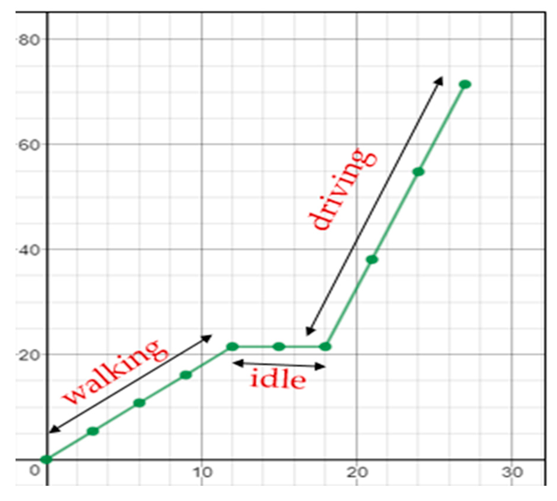
Here, the important concern is to differentiate whether the driver is walking, idle, or driving. Usually, the velocity of walking and driving can be easily differentiable. According to [26], the velocity of walking ranges from 1 ms−1 to 1.18 ms−1, while the velocity for running ranges from 2.97 ms−1 to 3.81 ms−1. Velocity can be calculated using Equation (6):
v = d t
where v = velocity, d = distance in meters, and t = time in seconds.
It is definite that the driving speed is much higher than walking and running, as shown in Figure 5. Here, the x-axis and y-axis denote time and distance, respectively. The distance changes slowly when a person walks, while it is in an idle state when he/she remains in the same position. When the person accelerates to drive, it means he/she is in a vehicle that moves fast. Therefore, it is possible to detect parking behavior by distinguishing the walking, running, idle and driving activities.

4. Proposed Method

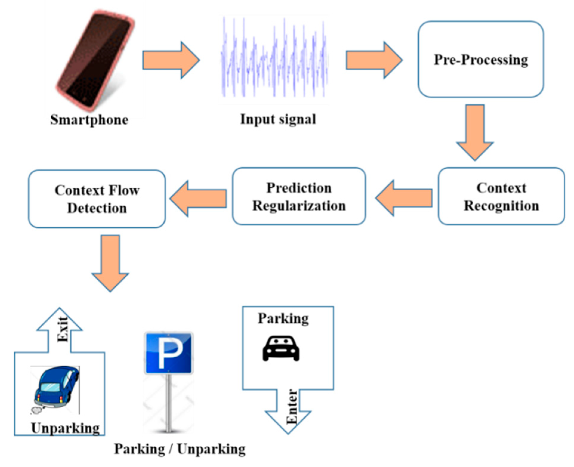
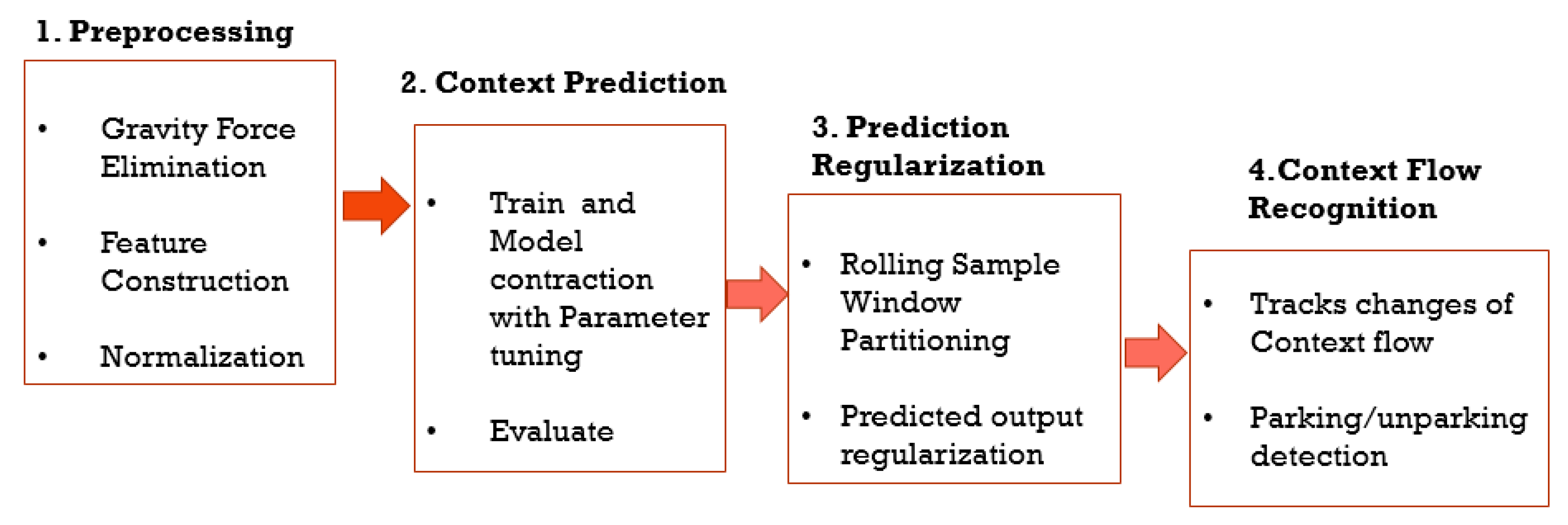
The overall effort of the proposed approach consists of four major components, which include pre-processing, context prediction (CP), prediction regularization (PR), and context flow recognition (CFR). Firstly, when a raw signal is received from the driver’s smartphone, a pre-processing step will be carried out to process the raw signal. Secondly, a process named CP will analyze the signal to predict the individual actions contained in the signal. Thirdly, PR is used to improve the result of CP which is followed by CFR. Lastly, CFR will be performed to recognize the flow of the driver’s context to conclude whether the driver is parking or unparking his/her vehicle. The block diagram of the proposed method is demonstrated in Figure 6.
Each of the major components will have subcomponents. The subcomponents of the major components are of are illustrated in Figure 7. The details of the proposed method are described in the following subsections.

4.1. Pre-Processing

The pre-processing steps applied in this work are explained with particulars in the following sections.

4.1.1. Gravity Force Elimination

The accelerometer data is always influenced by gravity. Consequently, it reads a magnitude value of g = 9.8 m/s2 even while it is not in an acceleration position, such as when a phone is on the table [27]. Likewise, it accelerates at 9.81 m/s2 towards the ground while its acceleration reads a magnitude value of 0 m/s2 when the device is in free-fall [27]. Therefore, in order to obtain position-independent acceleration readings, it is crucial to eliminate the effects of gravity. In the proposed approach, a low-pass filter and high-pass filter are presented to eradicate the gravity force influences, as follows:
g r a v i t y [ n ] = a l p h a × g r a v i t y [ n ] + ( 1 a l p h a ) e v e n t . v a l u e s [ n ]
l i n e r   a c c e l e r a t i o n [ n ] = e v e n t . v a l u e s [ n ] g r a v i t y [ n ]
Here, Equation (7) isolates the gravity force with a low-pass filter while Equation (8) removes the gravity force with a high-pass filter. The value alpha = 0.8 is a fixed value that is calculated as t/(t + dT) where t is the time constant of the low-pass filter that indicates the speed assumed to respond to an input, dT is the rate of the sensor event delivery and n stands for 0, 1, 3, which represents the x-, y-, and z-axis, respectively. A sensor event represents a sensor that holds and delivers information, such as sensor data and a timestamp. Using the above two formulas, the force of gravity can be eradicated to make the accelerometer position-independent.

4.1.2. Feature Construction

A feature in machine learning is an individual computable property that is also known as the distinguishing of an occurrence being observed. Features that are variable are also called attributes that are used to predict the outcome or targets. The values of features are called input values. The whole set of input values are called the feature vector or the attributes vector, informative and discriminative features that are crucial for effective classification. Feature construction is a way to extend the feature vector of a model by adding new features based on the existing features [28].
After collecting the raw data from the users, the following features are created in order to train the model. The new features are constructed by mathematical transformation of the existing features. Initially, there were six features, namely, ax, ay, az, gx, gy, and gz. These features are extended to eight features by constructing astd and gstd, where astd and gstd stand for the standard deviation of the three axes of the accelerometer and gyroscope, respectively. The formula that has been used for feature extraction is shown in Equation (9):
a s t d = 1 N i = 1 N ( a a ¯ ) 2
where N is the number of samples, a and a ¯ are the value of accelerometer sensor reading and mean of the sensor reading, respectively. Here, a stands for the values of the accelerometer in the x, y, and z axes. i = 1, 2 and 3 denote the ax, ay, and az axes of the accelerometer.
g s t d = 1 N i = 1 N ( g g ¯ ) 2
where N is the number of samples, and g and g ¯ are the values of the gyroscope sensor reading and mean of the sensor reading, respectively. Similarly, here g stands for the values of the gyroscope in x, y, and z axes. i = 1, 2, and 3 denote the gx, gy, and gz axes of the gyroscope.

4.1.3. Normalization

Conversely for artificial neural network (ANN), the input data is normalized so that all the inputs are within a comparable range. For instance, suppose that x1 and x2 are two inputs to the ANN and x1 varies from 0–0.5, whereas x2 varies from 0–1000. A change of 0.5 to x1 means a 100% change, while it only means a 0.005% change to x2. Hence, it is necessary to perform normalization for the ANN. The features are normalized by scaling unit variance and removing mean as follows:
z = x u s
where z is the standard score, and u and s represent the mean and standard deviation of the inputs, respectively.

4.2. Context Prediction (CP)

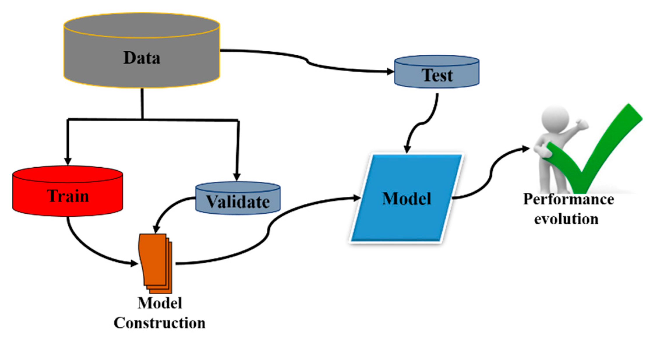
To predict the driver’s context (whether the driver is walking, driving, running, or idle), machine learning techniques are applied. The processes of CP are shown in Figure 8.
The dataset is isolated into three sets: dtrain, dvalidation and dtest, where dvalidation and dtest are kept unseen to the classifier, whereas dtrain is used to fit the model. The training set is used to train the classifier that fits the model, the validation set is used for parameter tuning and, lastly, the test set is used to evaluate the performance of the final trained model. The CP operation for classification is represented as follows:
c = φ ( X )
where φ represents a classifier operation, X represents the classifiers, and c denotes the driver’s context that would be the prediction result. The result of prediction determines the activity performed by the drivers. ANN, k-nearest neighbor (KNN), and RF have been employed for classification. The parameters that have been selected for the classifier are listed in Table 1. The parameters are selected empirically to obtain the best performance by parameter tuning with the dvalidation dataset.

4.3. Prediction Regularization (PR)

PR is an extension of the existing CP process. It is a vital step to determine CFR which concludes a parking or unparking event. It is to be noted that a complete sequence of transitions from walking to driving or from driving to walking must be observed to conclude a parking/unparking activity. A portion of the transition of is not sufficient to decide whether the driver is parking or releasing the parking spot because the driver context alternating from driving to idle or from idle to driving does not necessarily confirm a parking event. For example, a switch of context from driving to idle may occur while the driver is stuck in traffic and a context flow from idle to walking implies that the driver has started walking from an idle state. Therefore, a series of predicted parking activities has to be observed until it reaches a conclusion, whether parking or unparking. Although the classifiers are able to identify the context of the drivers correctly, there might yet be chances for classification errors for a single feature vector, especially when the phone is stirred from its preceding context to the next. A single classification can misguide the detection of parking/unparking action. For parking/unparking action recognition, even only an error of classification can be conflicting, as it might result in the detection of a wrong transition, such as a false parking detection event. An example of a misclassified context is presented in Table 2 which shows samples of classification errors in red.
In Table 2, the actual activities performed by a driver in 18 s is given in the first rows while the second row shows the CP results predicted by the classifier. The actual values imply the transition as walk → walk → walk → walk → walk → walk → walk → walk → walk → drive → drive → drive → drive → drive → drive → drive → drive → drive. From the actual transition, it can concluded that this is an unparking event. However due to some misclassification errors, some actual values are predicted wrongly (the wrong predictions are marked as red). The predicted values produce the flows as walk → drive → walk → walk → walk → drive → walk → walk → walk → drive → drive → drive → walk → drive → drive → drive → drive → walk. From the context flow formed by the predicted activities, it is confusing/difficult to determine whether it is parking or unparking event. In such a situation, it leads to a wrong transition, which results in a false parking detection result or an indecisive conclusion (whether it is a parking or unparking event).
To overcome this problem, an additional technique called PR is introduced to take into consideration the earlier outputs predicted by the classifier on a rolling window, and correlates the current classification output with the next outputs. More precisely, assume that O = {o*(1), o*(2), …, o*(n)} be the last n outputs of the driver activities predicted by the classifier. The current activity ac is figured as the most repeated values from O and returned as the classification output. It is to be noted that ac might not be the same as the recent predicted activity ap. PR has two steps which are: (a) rolling sample window (w) partitioning; and (b) predicted output regularization (o) as the actual output from each sample.
(a) Rolling Sample Window Partitioning
This step divides the total predicted outputs (o) into several windows (w) with m number of consecutive samples in each rolling window (w). Here the choice for m is important. Too small the size of m and too large the size of m yields a wrong decision. If a larger size of m is considered, there is a possibility that more than one activity might occur. As it takes one output from each rolling window, taking a larger size of m might, therefore, skip the actual transition. Since the output might contain four classes (e.g., walk, idle, run, and drive), the number of possible outputs n = 4. To choose mode (o), it is needed to pick a window size m at least double the number of classes, n. Since there is a possibility for a tie, one more sample is taken to make it an odd number to avoid a tie in each window interval. Thus, the size of m is calculated by Equation (13):
m = n × 2 + 1
where n is the number of possible outputs from CP, and m is the size of the predicted output samples in each window. Figure 9 illustrates the partitions of the rolling window and shows an example of sample partitions where the total number of samples predicted by the classifier is n. The size (m) of each window is set to 9 and the very first window w1st starts at sample 1. The consecutive window starts at the ((i − 1) × 9 + 1)th sample, where i = 1, 2, 3, …, n.
For the last sample window, it might not have exactly m number of samples. In that case, it examines how many remaining samples there are. If the number of samples n < o × 1 + 1, the last rolling window will be ignored, but if n > o × 1 + 1 or n = o × 1 + 1, the last rolling window will be considered.
(b) Predicted Output Regularization
In this research, mode refers to the most frequently occurring activity in the predicted output sample. The activity that has a mode in each predicted sample window out of m activities is chosen as it has mode value. For example, the mode of the window W(1) ({drive, walk, drive, drive, drive, idle, drive, drive, drive}) in Table 3 is driving as it is the most-frequent activity occurring in window 1. From the each of the rolling window it calculates the mode of outputs mode(o) with Equation (14) and selects it as the actual value:
M o d e ( o )   =   m a x o c c u r e n c e s ( { w a l k i n g ,   i d l e ,   r u n n i n g   d r i v i n g } )
where mode(o) is chosen predicted activity among walking, idle, running, and driving. maxoccurrences() finds which activity is most frequent in the rolling window. Selecting the mode of the predicted output is explained with an example below. Supposed that a number of n outputs are observed by the classifiers which are then divided into n/m window w where n is the total output samples and m is the size of the window. Suppose that the number of samples predicted by CP is 72. Thus, n = 72 and our window size m = 9, so it has altogether seven rolling windows. From the seven rolling windows, seven values will be selected as the actual values. The selection of actual values from each window is presented in Table 3.

4.4. Context Flow Recognition

In order to obtain the final output (parking or unparking event prediction), identification of the driver’s context flow is required. This compares the driver’s current activity ac with the next activity an from the output found by mode(o) in the previous step. If ac and an are same then it does not do anything, it just updates ac to an. However, if ac and an are not equal then it keeps track of the flow of context changes and updates ac to an. The CFR for a parking action is demonstrated in Table 4.
In Table 4, after the final iteration, the CFR provides drive → idle → walk instead of drive → drive → drive → idle → idle → walk, which is necessary to decide the action performed by the driver while parking or leaving the parking spot. With CFR, it identifies the parking or unparking activities. For example, if the driver’s context flow is driving → idle → walking then, based on the pattern of the context flow, it determines that the driver has parked her car and it decreases the total number of available parking spots with the following equation:
a = a 1
where a is the number of available parking spots. On the other hand, if the driver’s context flow is walking → idle→ driving then, from this pattern, it considers that the driver is unparking the car by releasing the parking spot and makes an increment of total available parking as follows:
( a   =   a   + 1 )

5. Results and Discussions

In order to validate the effectiveness of the proposed model, data has been collected from 60 healthy participants who performed four parking activities (idle, walking, running, and driving) by keeping the phone in different random positions, such as in the right hand, right pocket, left hand left pocket, handbag, back bag, in a chest pocket, the phone in a talking position, and the phone on a table. The participants were free to keep the phone in any rotation, angle, and position. Among the 60 participants, 40 are males and 20 are females.

5.1. Experiment on Context Recognition

To examine the context recognition’s accuracy with different sizes of training and testing samples three ratios for training experiments were tested: test splits ratio, which is 70:30 (23,417 rows for training, 10,036 rows for testing), 80:20 (26,762 rows for training and 6691 rows for testing), and 90:10 (30,107 rows for training, 3346 rows for testing). The accuracy for each classifier with the three split ratios is given in Figure 10.
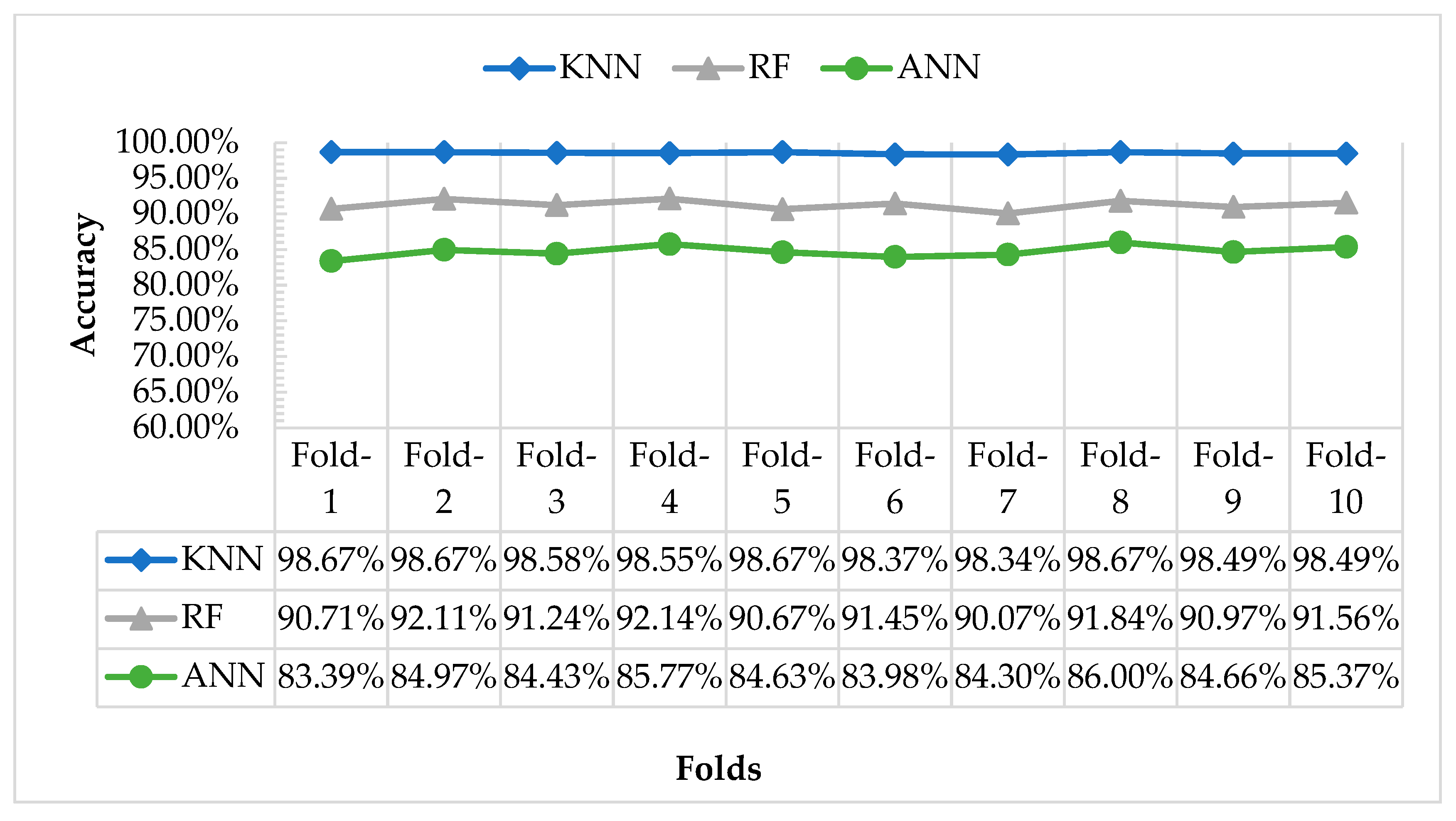
In order to check how well a model performs on different unseen data, it is recommended by many machine learning researchers to exploit K-fold cross-validation (CV). Therefore, K-fold cross-validation has been applied for validation in the experiment. The result of K-fold cross-validation is to perceive whether the 10-fold cross-validation delivers identical achievement. The 10-fold cross-validation accuracy for this research is presented in Figure 11.
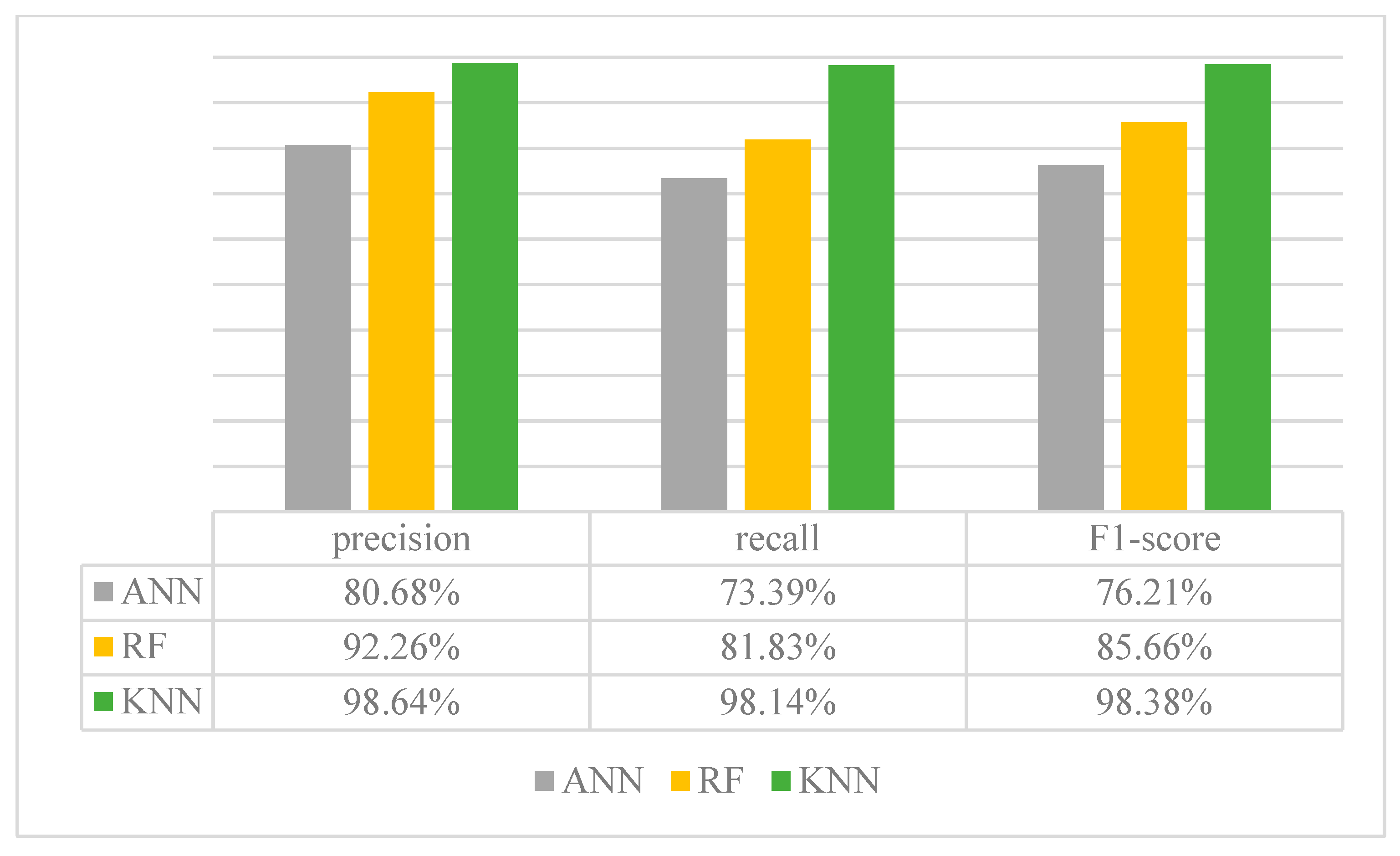
It is seen from Figure 11 that all the folds deliver nearly the same results. Thus, the accuracies of the 10-folds are seen well-adjusted. Furthermore, to appraise the context recognition’s enactment, the precision, recall, as well as F1-score for each of the classifiers have been computed. The calculation is made based on the observation of the true TP, TN, FP, and FN. Equations (17)–(19) are used to measure precision, recall, and F1-score, respectively. The results of precision, recall, and F1-score are shown in Figure 12.
P r e c i s i o n   =                 T P T P + F P
R e c a l l   =                 T P T P + F N
F1-score   = 2 ×     r e c a l l × p r e s i c i o n r e c a l l + p r e c i s i o n
where TP, FP, TN, and FN are the four commonly used counts for measuring performance in machine learning. Let sk be the one of the n testing samples, y(sk) denotes the real label of sk and ye(sk) represents the prediction result of sk. Assume that +1 and −1 are the positive and negative labels of a sample, respectively. These counts can be defined as follows:
T P = |   {   s k   |   y ( s k ) =   + 1 , y e ( s k ) =   + 1 } | ,
F P = |   { s k   |   y ( s k ) =   1 , y e ( s k ) =   + 1 } | ,
T N = |   { s k   |   y ( s k ) =   1 , y e ( s k ) =   1 } | ,
F N = |   { s k   |   y ( s k ) =   + 1 , y e ( s k ) =   1 } | ,
According to these definitions, when both predicted and real labels are positive then it is called a TP sample, and it is called TN when both real and predicted labels are negative. Provided the true value is positive and its prediction value is negative then it is called FN. On the other hand, if the real label is negative and predicted label is positive then it is called FP. Almost all the measures of machine learning performance rely on these four rudimentary counts.

5.2. Experiment Context Flow Recognition

Unlike the previous cases, a total of 120 parking/unparking events data were collected for practical evolution of parking/unparking recognition. Among the 120 parking events, 60 events are performed in the controlled environment with four fixed positions while another 60 are in random positions, such as in the left hand, right hand, left pocket, right pocket, backpack, and handbag. Here one parking/unparking event means a full trajectory of parking or unparking events. As an example, walking → driving = 1 unparking event similarly driving → walking = 1 parking event.
Note that there are three categories of CFR output which are “Parking”, “Unparking”, and “Unknown”. The three categories of CFR output are explained below:
  • Parking: If the output of CFR matches the flow of the parking list as shown in Figure 4.
  • Unparking: If the output of CFR matches the flow of the unparking list as shown in Figure 4.
  • Unknown: When the result of CFR is undefined and does not match any of the above two categories, then it is categorized as unknown. This output means that the action is unknown to CFR.
From Table 5, it can detect parking/unparking action regardless of the phone position. For example, the RF classifier detects 55 of 60 actions for fixed positions and 58 of 60 for the random position. Again, KNN can correctly detect 58 of 60 actions while the phone is in a fixed position and 56 of 60 while the phone is in random positions. Therefore, it is an indication that the parking/unparking detection does not depend on the phone position.
Apart from the above experiments, 10 more experiments with wrong inputs that are not associated with car parking have been performed to check the robustness of the algorithm. The purpose of the experiment with the wrong input is to assess whether the algorithm mistakenly detects cycling as driving activity. Therefore, instead of a car, the data is collected from cycling to test whether the algorithm wrongly addresses it as driving. Since it did not train cycling data during model construction, it expects to see that the actions are unknown to the algorithm. The result of the experiment of 10 actions with wrong inputs is given in Table 6 below. From Table 6, it is seen that the classifiers do not detect the wrong input as a parking action. Thus, it shows the robustness of the proposed algorithm that it does not entertain false input as correct input.
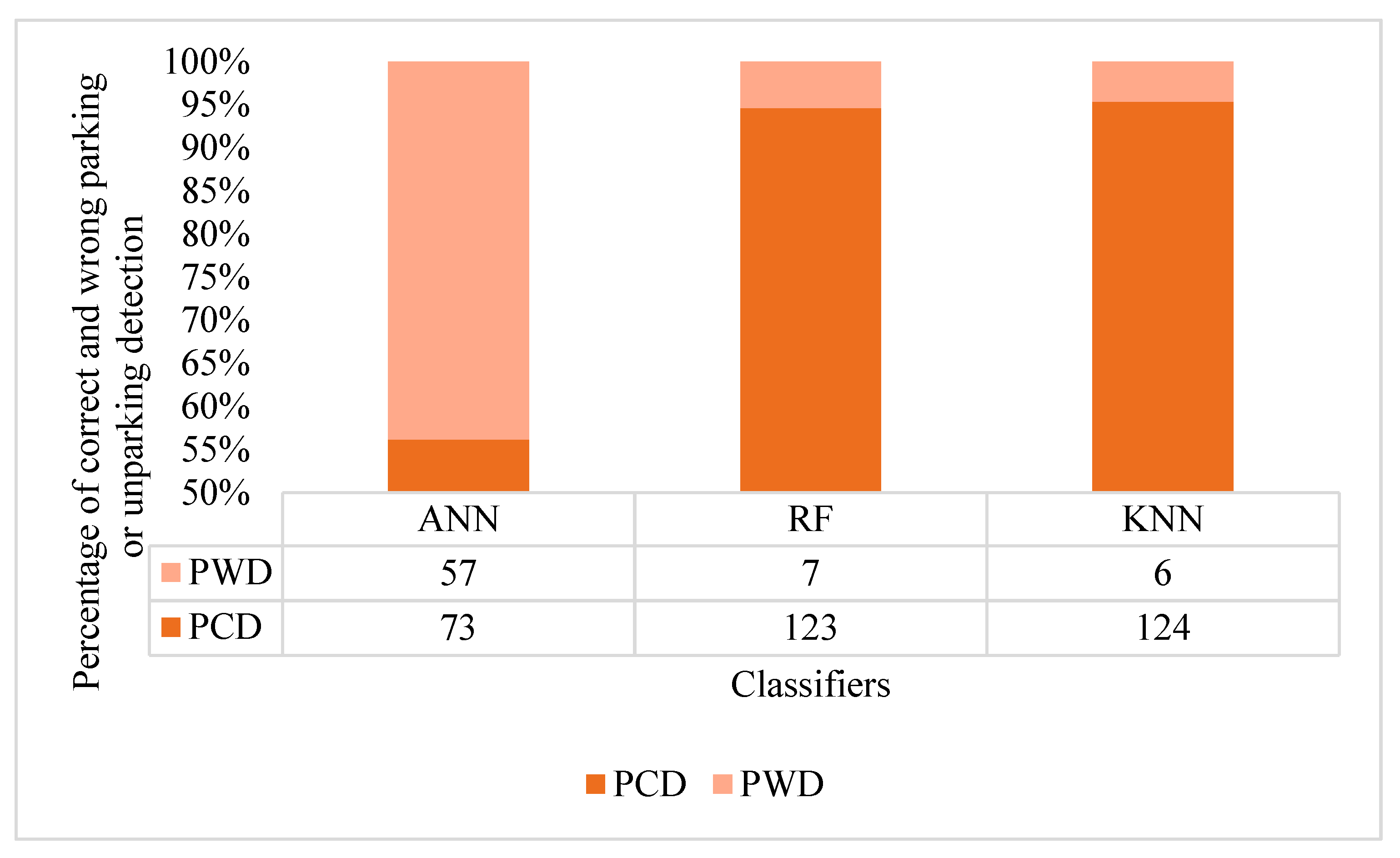
Finally, the overall performance of CFR with each classifier in detecting parking/unparking action is shown in Figure 13. Here percentage of correctly detection (PCD) and percentage of wrongly detection (PWD) stand for the number of correct detections and the number of the wrong detections, respectively. The percentage is calculated over 130 (120 parking/unparking + 10 wrong data experiment) parking/unparking experiments. The experimental result shows that ANN provides comparatively poor accuracy, while random forest (RF) and k-nearest neighbor (KNN) are seen to provide satisfactory results. Figure 13 illustrates that ANN correctly detects 56%, whereas the detection accuracy of RF and KNN are 95% and 95%, respectively.

6. Conclusions

Automatic detection of vehicles entering or leaving a parking space is an important step towards a smart parking system. By detecting a parking or unparking event, it is possible to conclude how many parking places are available in a parking zone. The existing systems deploy either cameras or external sensors, such as RFID, or an ultrasonic sensor that requries a vast amount of initial and maintenance cost that makes existing parking system difficult to implement in large-scale. This paper presents an approach to replace cameras or external sensors to detect outdoor parking or unparking actions by taking advantage of the rapid deployment of smartphones. The ultimate goal of this research is to automatically know whether a driver is parking or leaving from the parking area. By knowing whether the driver is parking or leaving at any time, it is possible to know the number of available parking spaces in a parking zone. The proposed method can accurately predict a parking/unparking event by analyzing the signals of a smartphone’s internal sensors, such as accelerometers and gyroscopes. Future work will be to broadcast the parking availability information to the other drivers who are looking for a parking space to realize a smart parking solution.

Author Contributions

Conceptualization: M.I.H.; methodology: M.I.H.; data collection software: M.I.H.; validation: M.I.H.; formal analysis: M.I.H. and G.K.O.M.; investigation: S.H.L. and M.I.H.; resources: G.K.O.M.; data collection: M.I.H.; writing—original draft preparation: M.I.H.; writing—review and editing: M.I.H., G.K.O.M., T.C., and F.H.; supervision: G.K.O.M.; project administration: G.K.O.M.; funding acquisition: G.K.O.M. The proof reading was done by all the authors.

Funding

This research is funded by Telekom Malaysia, grant number [MMUE/180024] and the Research Management Center of Multimedia University.

Acknowledgments

The authors thank Telecom Malaysia and Multimedia University—Research Management Center.

Conflicts of Interest

The authors declare no conflict of interest.

References

  1. Stenneth, L.; Wolfson, O.; Xu, B.; Yu, P.S. PhonePark: Street Parking Using Mobile Phones. In Proceedings of the IEEE 13th International Conference on Mobile Data Management, Bengular, India, 23–26 July 2012; pp. 278–279. [Google Scholar]
  2. Mathur, S.; Kaul, S.; Gruteser, M.; Trappe, W. ParkNet. In Proceedings of the MobiHoc S3 workshop on MobiHoc S3, New Orleans, LA, USA, 18–21 May 2009; p. 25. [Google Scholar]
  3. White, P.S. No Vacancy Park Slope’s Parking Problem And How to Fix It; Transportation Alternatives: New York, NY, USA, 27 February 2007. [Google Scholar]
  4. McCoy, K. Drivers Spend an Average of 17 Hours a Year Searching for Parking Spots. 2017. Available online: https://www.usatoday.com/story/money/2017/07/12/parking-pain-causes-financial-and-personal-strain/467637001/ (accessed on 5 May 2019).
  5. Hossen, M.I.; Goh, M.; Connie, T.; Aris, A.; Pei, W.L. A Review on Outdoor Parking Systems Using Feasibility of Mobile Sensors. In International Conference on Computational Science and Technology; Springer: Singapore, 2017; pp. 241–251. [Google Scholar]
  6. Nawaz, S.; Efstratiou, C.; Mascolo, C. ParkSense: A Smartphone Based Sensing System For On-Street Parking. In Proceedings of the 19th Annual International Conference on Mobile Computing & Networking (MobiCom’19), Miami, FL, USA, 30 September–4 October 2013; pp. 75–86. [Google Scholar]
  7. Lin, T.; Rivano, H.; le Mouel, F. A Survey of Smart Parking Solutions. IEEE Trans. Intell. Transp. Syst. 2017, 18, 3229–3253. [Google Scholar] [CrossRef] [Green Version]
  8. Kessler, S. How Smarter Parking Technology Will Reduce Traffic Congestion. 2011. Available online: https://mashable.com/2011/04/13/smart-parking-tech/#yRd0m1SOvOqB (accessed on 3 December 2018).
  9. Kinyanjui, K.E.; Kahonge, A.M. Mobile Phone-Based Parking System. Int. J. Inf. Technol. Control Autom. 2013, 3, 2013. [Google Scholar] [CrossRef]
  10. Lan, K.C.; Shih, W.Y. An intelligent driver location system for smart parking. Expert Syst. Appl. 2014, 41, 2443–2456. [Google Scholar] [CrossRef]
  11. Hussain, G.; Jabbar, M.S.; Cho, J.D.; Bae, S. Indoor Positioning System: A New Approach Based on LSTM and Two Stage Activity Classification. Electronics 2019, 8, 375. [Google Scholar] [CrossRef]
  12. Hegde, N.; Sazonov, E.; Hegde, N.; Sazonov, E. SmartStep: A Fully Integrated, Low-Power Insole Monitor. Electronics 2014, 3, 381–397. [Google Scholar] [CrossRef] [Green Version]
  13. Fraifer, M.; Fernström, M. Investigation of smart parking systems and their technologies. In Proceedings of the Thirty Seventh International Conference on Information Systems, IoT Smart City Challenges Applications (ISCA 2016), Dublin, Ireland, 9 December 2016; pp. 1–14. [Google Scholar]
  14. Van Melsen, N. Automated Car Parking History. 2013. Available online: http://www.parking-net.com/parking-industry-blog/skyline-parking-ag/history (accessed on 5 December 2018).
  15. Kosowski, M.; Wojcikowski, M.; Czyzewski, A. Vision-based parking lot occupancy evaluation system using 2D separable discrete wavelet transform. Bull. Pol. Acad. Sci. Tech. Sci. 2015, 63, 569–573. [Google Scholar] [CrossRef] [Green Version]
  16. Zhang, L.; Huang, J.; Li, X.; Xiong, L. Vision-Based Parking-Slot Detection: A DCNN-Based Approach and a Large-Scale Benchmark Dataset. IEEE Trans. Image Process. 2018, 27, 5350–5364. [Google Scholar] [CrossRef] [PubMed]
  17. Shih, S.-E.; Tsai, W.-H. A Convenient Vision-Based System for Automatic Detection of Parking Spaces in Indoor Parking Lots Using Wide-Angle Cameras. IEEE Trans. Veh. Technol. 2014, 63, 2521–2532. [Google Scholar] [CrossRef] [Green Version]
  18. Suhr, J.K.; Jung, H.G. Sensor Fusion-Based Vacant Parking Slot Detection and Tracking. IEEE Trans. Intell. Transp. Syst. 2014, 15, 21–36. [Google Scholar] [CrossRef]
  19. Jung, H.G.; Cho, Y.H.; Yoon, P.J.; Kim, J. Scanning Laser Radar-Based Target Position Designation for Parking Aid System. IEEE Trans. Intell. Transp. Syst. 2008, 9, 406–424. [Google Scholar] [CrossRef]
  20. Vera-Gómez, J.A.; Quesada-Arencibia, A.; García, C.R.; Moreno, R.S.; Hernández, F.G. An Intelligent Parking Management System for Urban Areas. Sensors 2016, 16, 931. [Google Scholar] [CrossRef] [PubMed]
  21. Reve, S.V.; Choudhri, S. Management of Car Parking System Using Wireless Sensor Network. Int. J. Emerg. Technol. Adv. Eng. 2012, 2, 7. [Google Scholar]
  22. Le Nguyen, T.; Zhang, Y.; Griss, M. ProbIN: Probabilistic Inertial Navigation. In Proceedings of the IEEE 7th International Conference Mobile Ad-Hoc Sensor System (MASS 2010), San Francisco, CA, USA, 8–12 November 2010; pp. 650–657. [Google Scholar]
  23. Biondi, S.; Monteleone, S.; la Torre, G.; Catania, V. A Context-Aware Smart Parking System. In Proceedings of the 12th International Conference on Signal Image Technology and Internet Based Systems, Naples, Italy, 28 November–1 December 2016; pp. 450–454. [Google Scholar]
  24. Nandugudi, A.; Ki, T.; Nuessle, C.; Challen, G. PocketParker: Pocketsourcing parking lot availability. In Proceedings of the ACM International Joint Conference on Pervasive and Ubiquitous Computing(UbiComp ’14Adjunct), Seattle, WA, USA, 13–17 September 2014; pp. 963–973. [Google Scholar]
  25. Moses, N.; Chincholkar, Y.D. Smart Parking System for Monitoring Vacant Parking. Int. J. Adv. Res. Comput. Commun. Eng. 2016, 5, 717–720. [Google Scholar]
  26. Long, L.L.; Srinivasan, M. Walking, running, and resting under time, distance, and average speed constraints: Optimality of walk-run-rest mixtures. J. R. Soc. Interface 2013, 10, 20120980. [Google Scholar] [CrossRef]
  27. Tate, D.R. Acceleration Due to Gravity at the National Bureau of Standards. J. Res. Natl. Bur. Stand. C Eng. Instrum. 1965, 72, 20. [Google Scholar]
  28. Coates, A.; Arbor, A.; Ng, A.Y. An Analysis of Single-Layer Networks in Unsupervised Feature Learning. In Proceedings of the Fourteenth International Conference on Artificial Intelligence and Statistics (Aistats), Ft. Lauderdale, FL, USA, 11–13 April 2011. [Google Scholar]
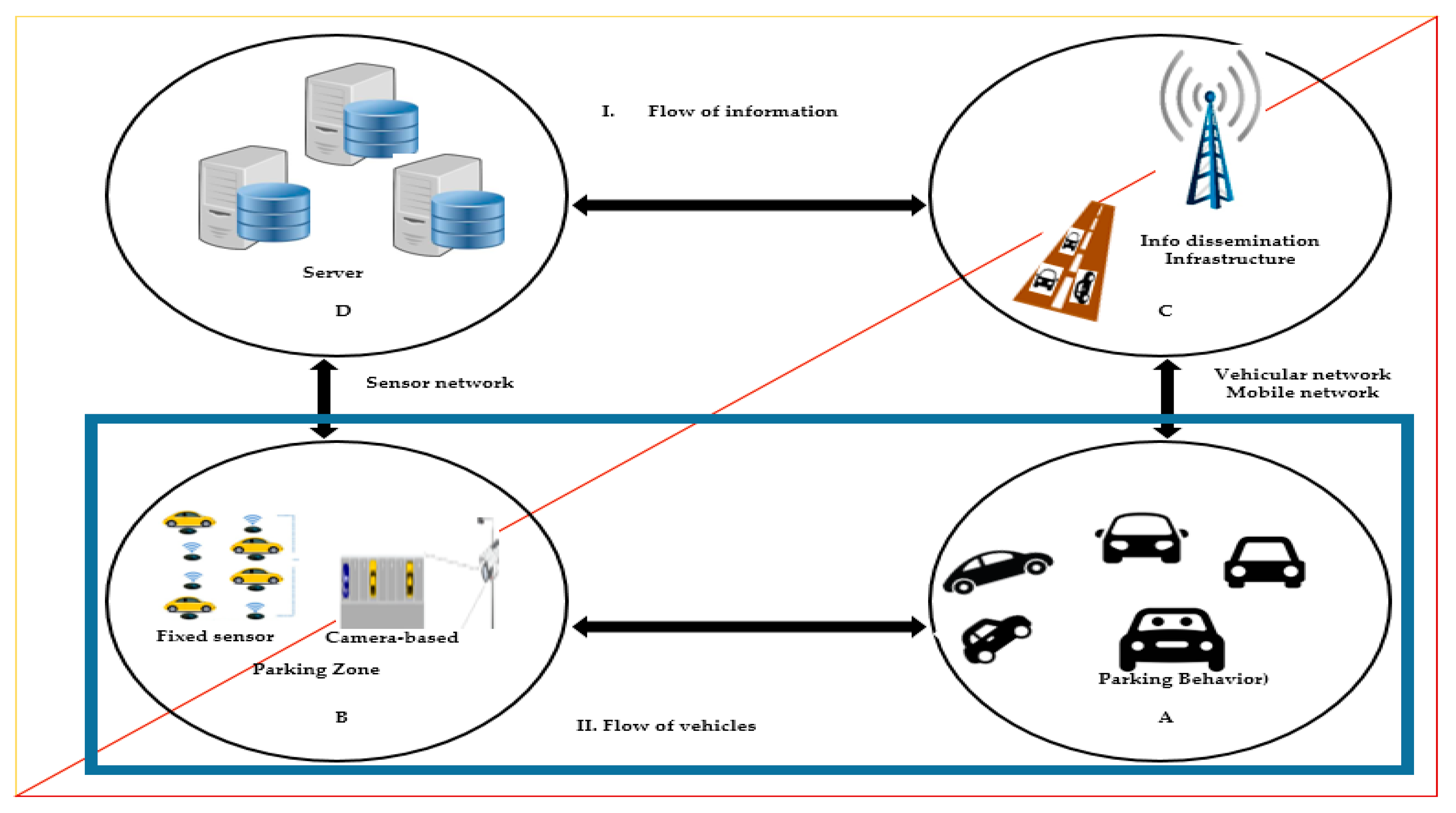
Figure 1. The ecosystem of the typical parking system which has two main sections, named flow of information (I) and flow of vehicles (II).
Electronics 08 00784 g001
Figure 2. Reference model of smartphone-based parking systems.
Electronics 08 00784 g002
Figure 3. The theoretical idea of the proposed system. Parking and unparking examples are shown in (a) and (b) respectively.
Electronics 08 00784 g003
Figure 4. Activity theory diagram of typical activity flows for parking and unparking. Unparking and parking activity flows are shown in (a) and (b) respectively.
Electronics 08 00784 g004
Figure 5. Walking, idle and driving graph (speed vs. time).
Electronics 08 00784 g005
Figure 6. Major steps of the proposed system.
Electronics 08 00784 g006
Figure 7. Sub-processes of major steps of the proposed system.
Electronics 08 00784 g007
Figure 8. Processes of context prediction.
Electronics 08 00784 g008
Figure 9. The partition of total predicted samples in each rolling window.
Electronics 08 00784 g009
Figure 10. Accuracy of three split ratios (70:30, 80:20, and 90:10) of training vs. testing datasets.
Electronics 08 00784 g010
Figure 11. The comparison of 10-fold cross-validation accuracy.
Electronics 08 00784 g011
Figure 12. Precision, recall, and F1-score of each classifier.
Electronics 08 00784 g012
Figure 13. Overall performance of context flow recognition (CFR) as a percentage with each classifier in detecting a parking/unparking action.
Electronics 08 00784 g013
Table 1. The parameters that have been selected for the classifiers.
Artificial Neural Network (ANN)Random Forest (RF)K-Nearest Neighbor (KNN)
activation = ‘relu’min_samples_split = 8n_neighbors = 15
solver = ‘adam’max_leaf_nodes= None-
alpha = 0.001, hidden_layer_sizn_estimator = 24-
e = (20, 8), random_state=1max_depth = 71-
-min_samples_leaf = 6-
-min_weight_fraction_leaf = 0.0-
-random_state = 50-
-criterion = ‘gini’-
-max_features = ‘auto’-
Table 2. An example of a misclassified context by the classifier.
Actualwwwwwwwwwddddddddd
Predictedwdwwwdwwwdddwddddw
Table 3. Example of finding the mode(o) of context prediction (CP) in each rolling window.
-W(1)W(2)W(3)W(4)W(5)W(6)W(7)
m consecutive outputs in each window wdrivewalkdrivewalkidlewalkidle
walkdrivedrivewalkwalkwalkwalk
drivedrivedriveidleidlewalkwalk
drivedrivewalkidleidlewalkwalk
driveidledriveidleidlewalkRun
idleidleRunidleidlewalkwalk
drivedrivedriveidleidlewalkwalk
driverundriveidleidleidlewalk
drivedrivedriveidleidlewalkwalk
mode(o)drivedrivedriveidleidlewalkwalk
Table 4. Example of context flow recognition (CFR).
Activities from Each Rolling WindowDrive (current)Drive (next)DriveIdleIdleWalkWalk
Iteration 1Drive (current)Drive (next)IdleIdleWalkWalk
Iteration 2Drive (current)Idle (next)IdleWalkWalk
Iteration 2DriveIdle (current)Idle(next)WalkWalk
Iteration 4DriveIdle (current)Walk (next)Walk
Iteration 5DriveIdleWalk (current)Walk (next)
Iteration 6DriveIdleWalk (current)Walk (next)
Iteration 7DriveIdleWalk
Table 5. Performance of parking/unparking detection for the classifiers.
Phone’s
Position
Number of Correctly Identified Exp
KNNANNRF
Fixed582955
Random563458
Overall11463113
Table 6. Result of experiment with wrong inputs data.
-ANNRFKNN
Unknown101010
Detected000