Experimental Demonstration of Single-Channel EEG Signal Using 32 × 32 Pixel OLED Screen and Camera


Abstract
1. Introduction
- The link distance of 5.5 m is achieved, in comparison to the results of available literature of EEG and VLC.
- The proposed system will be beneficial in the healthcare environment, such as hospitals, where the RF technology is expensive and suffers from Electromagnetic Interference (EMI).
- Due to bit rate being limited by camera frame rate, the achievable rate in the proposed research work in this paper is 2.8 kbps. The bit rate of 2.8 kbps is enough to transmit single-channel EEG transmission using VL-OCC.
2. Related Works
2.1. Current EEG Procedure in Hospitals and RF-Based EEG Products
2.2. Recent Work on Visible Light Communication for EEG
3. VL-OCC System Architecture and Applications
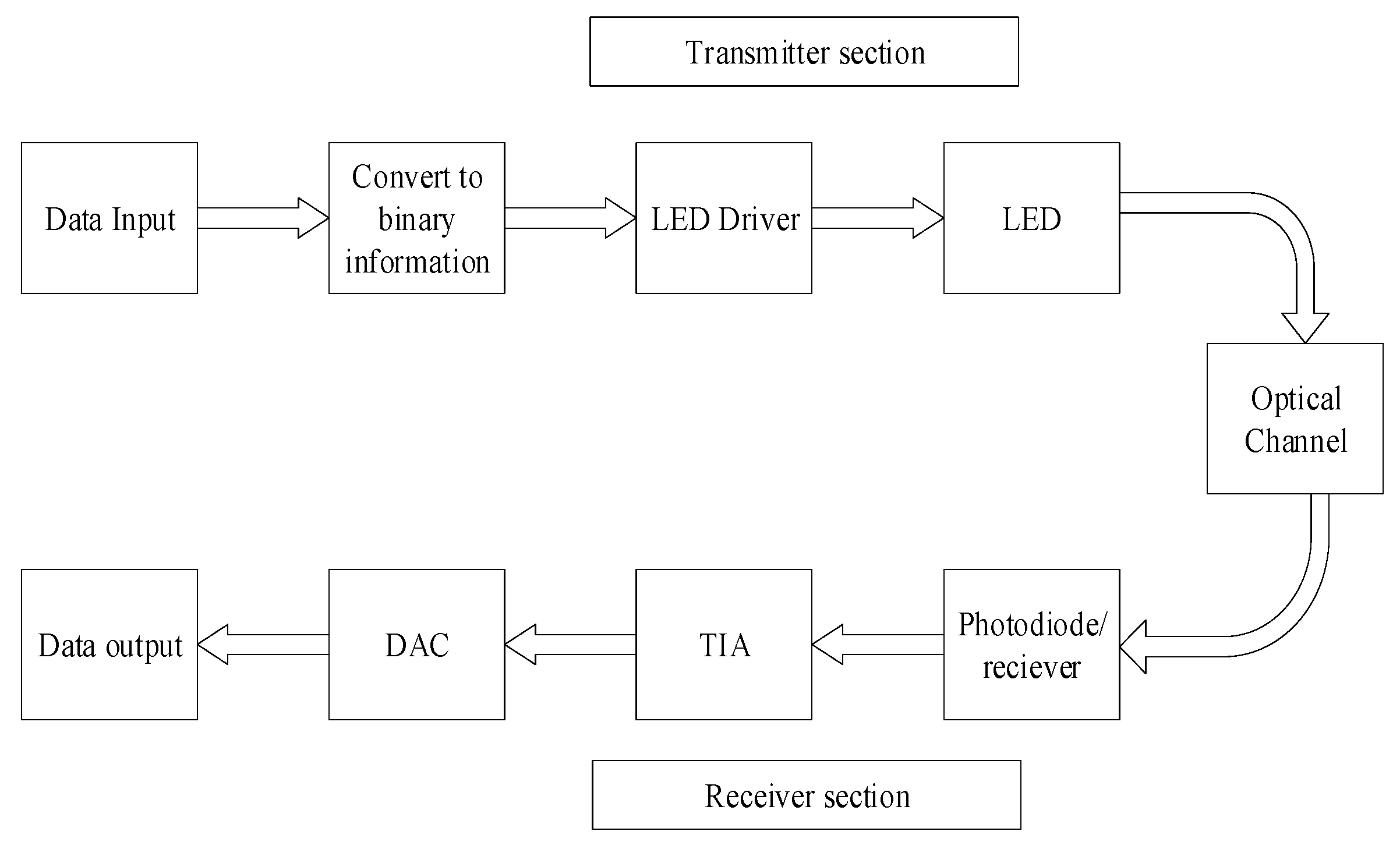
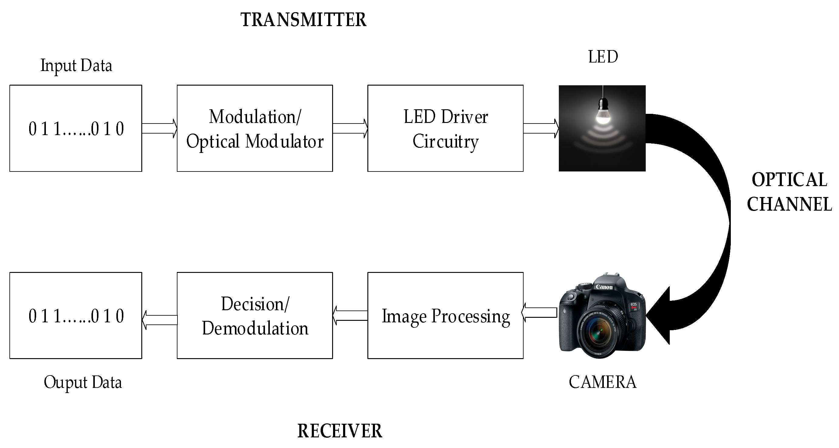
3.1. Brief Description of the VLC System
3.2. VL-OCC System Architecture
3.3. VL-OCC Applications
- (1)
- (2)
- Indoor situating: One of the prospective utilizations of OCC frameworks would be exact indoor situating, where LEDs, utilized as a part of an indoor situation, are given a one of a kind (ID) code, and a smartphone or laptop with an inherent camera can be utilized to viably find gadgets and individuals inside a room [48].
- (3)
- Computerized signage: Presently advanced/digital signage has turned into the most well-known medium among organizations for broadcasting or offering coupons to clients. Watchers might utilize their cell phones to get data from advanced signage, hence providing ongoing screen-to-camera correspondence behind the scenes [49,50].
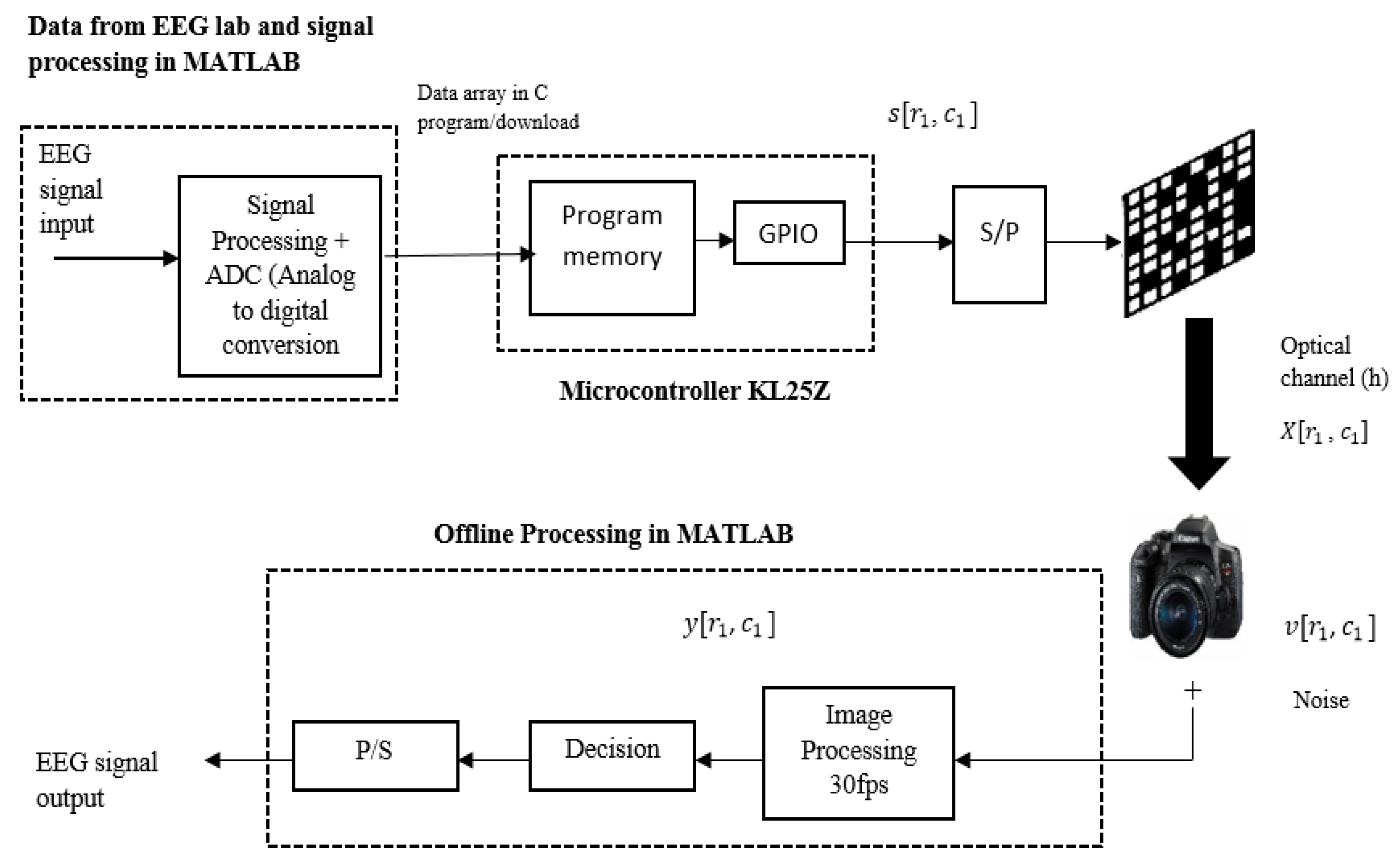
4. Proposed EEG VL-OCC System Modelling
5. Experiments and Results
5.1. Extraction of EEG Signal from EEGtoolbox
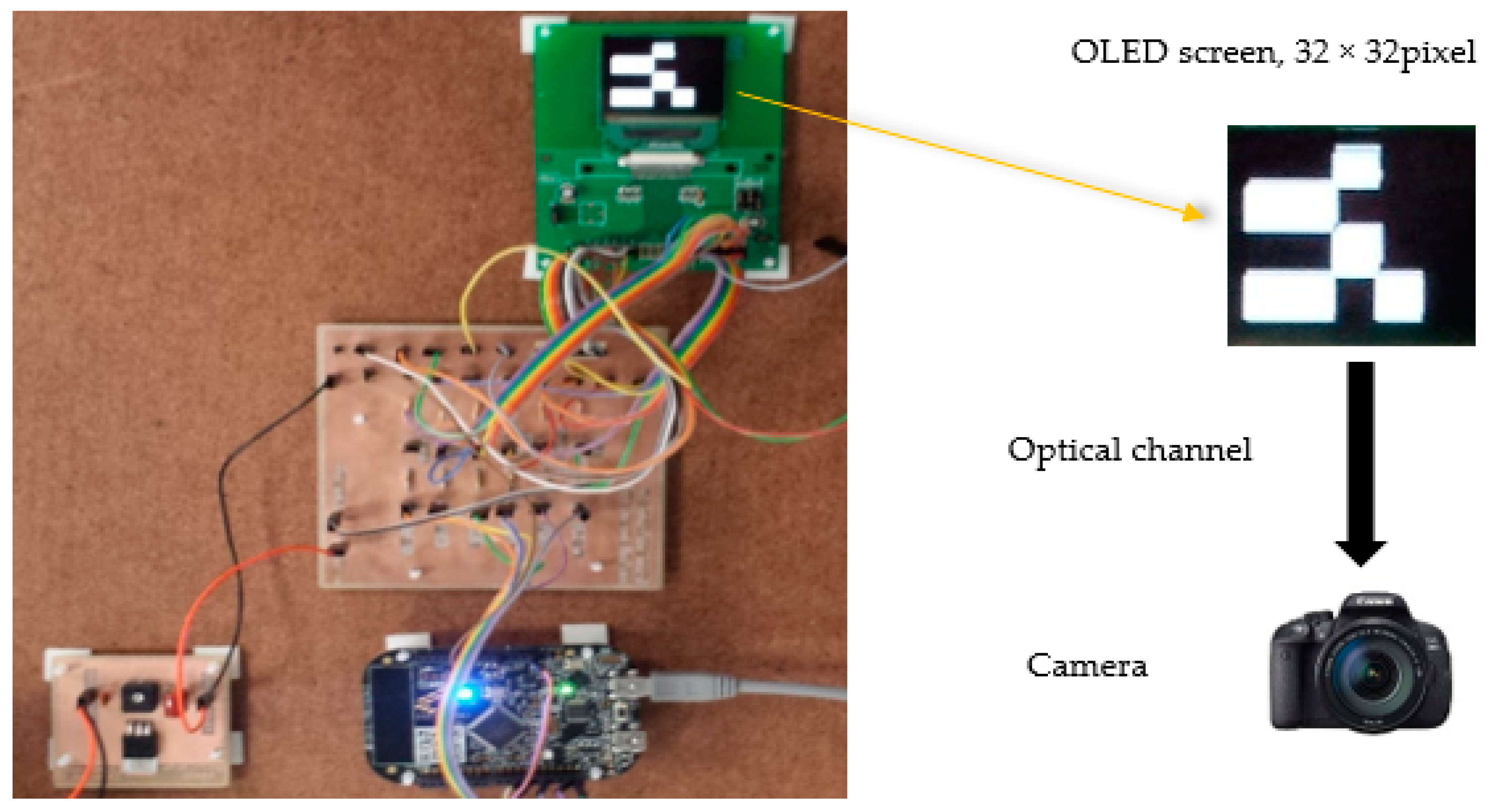
5.2. Experimental Set Up and Hardware Description
5.3. Results Analysis and Discussion
6. Conclusions
Author Contributions
Funding
Conflicts of Interest
References
- Nezhad, M.H.; Subari, K.S.; Yahyavi, M. Improvement of wireless transmission system performance for EEG signals based on development of scalar quantization. J. Electr. Bioimpedance 2013, 4, 62–72. [Google Scholar]
- Hasan, M.K.; Shahjalal, M.; Chowdhury, M.Z.; Jang, Y.M. Access point selection in hybrid OCC/RF Ehealth architecture for real-time remote patient monitoring. In Proceedings of the 9th International Conference on Information and Communication Technology Convergence (ICTC 2018), Jeju Island, Korea, 17–19 October 2018; pp. 716–719. [Google Scholar] [CrossRef]
- Dhatchayeny, D.R.; Sewaiwar, A.; Tiwari, S.V.; Chung, Y.H. Experimental biomedical EEG signal transmission using VLC. IEEE Sens. J. 2015, 15, 5386–5387. [Google Scholar] [CrossRef]
- Rachim, V.P.; Jiang, Y.; Lee, H.S.; Chung, W.Y. Demonstration of long-distance hazard-free wearable monitioring system using mobile phone visible light. Opt. Express 2017, 25, 713–719. [Google Scholar] [CrossRef] [PubMed]
- Jungnickel, V.; Uysal, M.; Ghassemlooy, Z. A European view on the next generation optical wireless communication standard. In Proceedings of the 2015 IEEE Conference on Standards for Communications and Networking (CSCN 2015), Tokyo, Japan, 28–30 October 2015. [Google Scholar]
- Goto, Y.; Takai, I.; Yamazato, T.; Okado, H.; Fuji, T.; Kawahito, S.; Arai, S.; Yendo, T.; Kamakura, K. A new automotive VLC system using optical communication image sensor. IEEE Photonic J. 2016, 8, 1–17. [Google Scholar] [CrossRef]
- Ong, Z.; Chung, W.Y. Long range VLC temperature monitoring system using CMOS of mobile camera. IEEE Sens. J. 2015, 16, 1508–1509. [Google Scholar] [CrossRef]
- Ghassemlooy, Z.; Popoola, W.; Rajbhandari, S. Optical Wireless Communications: System and Channel Modelling with MATLAB; CRC Press: Boca Raton, FL, USA, 2013; Volume 8, pp. 443–444. [Google Scholar]
- Haigh, P.A.; Bausi, F.; Le Minh, H.; Papakonstantinou, I.; Popoola, W.; Burton, A.; Cacialli, F. Wavelength-multiplexed polymer LEDs: Towards 55 Mb/s organic visible light communications. IEEE J. Sel. Areas Commun. 2015, 33, 1819–1828. [Google Scholar] [CrossRef]
- Haigh, P.A.; Ghassemlooy, Z.; Papakonstantinou, I. 1.4-Mb/s white organic LED transmission system using discrete multitone modulation. IEEE Photonic Technol. Lett. 2013, 25, 615–618. [Google Scholar] [CrossRef]
- Aoyama, H.; Oshima, M. Visible light communication using a conventional image sensor. In Proceedings of the IEEE 12th Annual Consumer Commununications Network Conference (CCNC 2015), Las Vegas, NV, USA, 9–12 January 2015; pp. 103–108. [Google Scholar]
- Roberts, R.D. Space-time forward error correction for dimmable undersampled frequency shift ON-OFF keying camera communications (CamCom). In Proceedings of the 5th International Conference Ubiquitous and Future Networks (ICUFN 2013), Da Nang, Vietnam, 2–5 July 2013; pp. 459–464. [Google Scholar]
- Ashok, A.; Jain, S.; Gruteser, M.; Mandayam, N.; Yuan, W.; Dana, K. Capacity of pervasive camera based communication under perspective distortions. In Proceedings of the 2014 IEEE International Conference on Pervasive Computing and Communications (PerCom 2014), Budapest, Hungary, 24–28 March 2014; pp. 112–120. [Google Scholar]
- Takai, I.; Harada, T.; Andoh, M.; Yasutomi, K.; Kagawa, K.; Kawahito, S. Optical vehicle-to-vehicle communication system using LED transmitter and camera receiver. IEEE Photonic J. 2014, 6, 1–14. [Google Scholar] [CrossRef]
- Chow, C.W.; Chen, C.Y.; Chen, S.H. Enhancement of signal performance in LED visible light communications using mobile phone camera. IEEE Photonic J. 2015, 7, 7903607. [Google Scholar] [CrossRef]
- Cao, Y.; Song, H.; Kaiwartya, O.; Zhou, B.; Zhuang, Y.; Cao, Y.; Zhang, X. Mobile edge computing for big-data-enabled electric vehicle charging. IEEE Commun. Mag. 2018, 56, 150–156. [Google Scholar] [CrossRef]
- Prasad, M.; Liu, Y.T.; Li, D.L.; Lin, C.T.; Shah, R.R.; Kaiwartya, O.P. A new mechanism for data visualization with TSK-type preprocessed collaborative fuzzy rule based system. J. Artif. Intell. Soft Comput. Res. 2017, 7, 33–46. [Google Scholar] [CrossRef]
- Cao, Y.; Kaiwartya, O.; Wang, R.; Jiang, T.; Cao, Y.; Aslam, N.; Sexton, G. Toward efficient, scalable, and coordinated on-the-move EV charging management. IEEE Wirel. Commun. 2017, 24, 66–73. [Google Scholar] [CrossRef]
- Aliyu, A.; Abdullah, A.H.; Kaiwartya, O.; Cao, Y.; Lloret, J.; Aslam, N.; Joda, U.M. Towards video streaming in IoT Environments: Vehicular communication perspective. Comput. Commun. 2018, 118, 93–119. [Google Scholar] [CrossRef]
- Khasawneh, A.; Latiff, M.S.B.A.; Kaiwartya, O.; Chizari, H. A reliable energy-efficient pressure-based routing protocol for underwater wireless sensor network. Wirel. Netw. 2018, 24, 2061–2075. [Google Scholar] [CrossRef]
- Kaiwartya, O.; Abdullah, A.H.; Cao, Y.; Lloret, J.; Kumar, S.; Shah, R.R.; Prasad, M.; Prakash, S. Virtualization in wireless sensor networks: Fault tolerant embedding for internet of things. IEEE Internet Things J. 2018, 5, 571–580. [Google Scholar] [CrossRef]
- Farhan, L.; Kharel, R.; Kaiwartya, O.; Hammoudeh, M.; Adebisi, B. Towards green computing for Internet of things: Energy oriented path and message scheduling approach. Sustain. Cities Soc. 2018, 38, 195–204. [Google Scholar] [CrossRef]
- Chatterjee, S.; Miller, A. Biomedical Instrumentation Systems; Delmar CENGAGE Learning: Clifton Park, NY, USA, 2010. [Google Scholar]
- Luan, B.; Jia, W.; Thirumala, P.D.; Balzer, J.; Gao, D.; Sun, M. A feasibility study on a single-unit wireless EEG sensor. In Proceedings of the 12th International Conference on Signal Processing (ICSP 2014), Hangzhou, China, 19–23 October 2014; pp. 2282–2285. [Google Scholar]
- Lin, C.-H.; Chuang, C.-H.; Huang, C.-H.; Tsai, S.-F.; Lu, S.-W.; Chen, T.-H.; Ko, L.-W. Wireless and wearable EEG system for evaluating driver vigilance. IEEE Trans. Biomed. Circuits Syst. 2014, 8, 165–176. [Google Scholar]
- Lee, S.M.; Kim, J.H.; Park, C.; Hwang, J.; Hong, J.S.; Lee, K.H.; Lee, S.H. Self-adhesive and capacitive carbon nanotube-based electrode to record electroencephalograph signals from the hairy scalp. IEEE Trans. Biomed. Eng. 2016, 63, 138–147. [Google Scholar] [CrossRef]
- Huang, Y.-J.; Wu, C.-Y.; Wong, A.M.-K.; Lin, B.-S. Novel active comb-shaped dry electrode for EEG measurement in hairy site. IEEE Trans. Biomed. Eng. 2015, 62, 256–263. [Google Scholar] [CrossRef]
- Yu, Y.-H.; Lu, S.-W.; Chuang, C.-H.; King, J.-T.; Chang, C.-L.; Chen, S.; Chen, S.-F.; Lin, C.-T. An inflatable and wearable wireless system for making 32-channel electroencephalogram measurements. IEEE Trans. Neural Syst. Rehab. Eng. 2016, 24, 806–813. [Google Scholar] [CrossRef]
- Goverdovsky, V.; Looney, D.; Kidmose, P.; Mandic, D.P. In-ear EEG from viscoelastic generic earpieces: Robust and unobtrusive 24/7 monitoring. IEEE Sens. J. 2016, 16, 271–277. [Google Scholar] [CrossRef]
- Xu, R.; Jiang, N.; Dosen, S.; Lin, C.; Mrachacz-Kersting, N.; Dremstrup, K.; Farina, D. Endogenous sensory discrimination and selection by a fast brain switch for a high transfer rate brain-computer interface. IEEE Trans. Neural Syst. Rehab. Eng. 2016, 24, 901–910. [Google Scholar] [CrossRef] [PubMed]
- Mihajlovic, V.; Grundlehner, B.; Vullers, R.; Penders, J. 1.4-Mb/s white organic LED transmission system using discrete multitone modulation; Wearable, Wireless EEg solutions in Daily Life Applications: What we are missing? IEEE J. Biomed. Health Inform. 2015, 25, 615–618. [Google Scholar]
- NeuroSky. Available online: http://www.neurosky.com (accessed on 27 April 2019).
- Emotiv. Available online: http://emotiv.com (accessed on 27 April 2019).
- G.Nautillus. Available online: http://www.gtec.at/Products/Hardware-and-Accessories/g.Nautilus-Specs-Features (accessed on 27 April 2019).
- Mindo. Available online: http://mindo.com.tw/en/goods.php?act=view&no=4 (accessed on 27 April 2019).
- Cognionics. Available online: http://www.cognionics.com/index.php/products/hd-eeg-systems/quick-20-dry-headset (accessed on 27 April 2019).
- Enobio. Available online: http://www.neuroelectrics.com/products/enobio/ (accessed on 27 April 2019).
- Ng, X.-W.; Chung, W.-Y. VLC-based medical healthcare information system. Biomed. Eng. Appl. Basis Commun. 2012, 24, 155–163. [Google Scholar] [CrossRef]
- Zhang, Q.; Wang, P.; Liu, Y.; Peng, B.; Zhou, Y.; Zhou, Z.; Dai, Y. A real-time wireless wearable electroencephalography system based on Support Vector Machine for encephalopathy daily monitoring. Int. J. Distrib. Sens. Netw 2018. [Google Scholar] [CrossRef]
- Aggarwal, G.; Dai, X.; Binns, R.; Saatchi, R.; Busawon, K.; Bentley, E. Wireless EEG signal transmission using visible light optical camera communication. In Applications of Computing and Communication Technologies; Deka, G., Kaiwartya, O., Vashisth, P., Rathee, P., Eds.; Springer: Singapore, 2018; Volume 899, pp. 152–161. [Google Scholar]
- Vu, T.L.; Nguyen, T.; Kim, C.S.; Sin, E.B.; Jeong, J.; Jang, Y.M. Survey of indoor optical camera communication (OCC) systems for the Internet of lights. In Proceedings of the 2017 International Conference on Information and Communication Technology Convergence (ICTC 2017), Jeju Island, Korea, 18–20 October 2017; pp. 700–703. [Google Scholar] [CrossRef]
- Islam, A.; Hossan, M.T.; Jang, Y.M. Convolutional neural network scheme–based optical camera communication system for intelligent Internet of vehicles. Int. J. Distrib. Sens. Netw. 2018, 14. [Google Scholar] [CrossRef]
- Teli, S.; Chung, Y. Selective capture based high-speed optical vehicular signaling system. Signal Process. Image Commun. 2018, 68, 241–248. [Google Scholar] [CrossRef]
- Ifthekhar, M.S.; Hossain, M.A.; Hong, C.H.; Jang, Y.M. Radiometric and geometric camera model for optical camera communications. In Proceedings of the 2015 Seventh International Conference on Ubiquitous and Future Networks, Sapporo, Japan, 7–10 July 2015; pp. 53–57. [Google Scholar] [CrossRef]
- Yamazato, T.; Kinoshita, M.; Arai, S.; Souke, E.; Yendo, T.; Fujii, T.; Kamakura, K.; Okada, H. Vehicle motion and pixel illumination modeling for image sensor based visible light communication. IEEE J. Sel. Areas Commun. 2015, 33, 1793–1805. [Google Scholar] [CrossRef]
- Wu, S.; Wang, H.; Youn, C.-H. Visible light communications for 5Gwireless networking systems: From fixed to mobile communications. IEEE Netw. 2014, 28, 41–45. [Google Scholar] [CrossRef]
- Iizuka, N. OCC Proposal of Scope of Standardization and Applications. IEEE 802.15 SG7a Standardization Documents; IEEE: Piscataway, NJ, USA, 2014. [Google Scholar]
- Shahjalal, M.; Hossan, M.T.; Hasan, M.K.; Chowdhury, M.Z.; Le, N.T.; Jang, Y.M. An implementation approach and performance analysis of image sensor based multilateral indoor localization and navigation system. Wirel. Commun. Mob. Comput. 2018, 2018, 7680780. [Google Scholar] [CrossRef]
- Deguchi, J.; Yamagishi, T.; Majima, H. A 1.4Mpixel CMOS image sensor with multiple row-rescan based data sampling for optical camera communication. In Proceedings of the Asian Solid-State Circuits Conference (A-SSCC 2014), KaoHsiung, Taiwan, 10–12 November 2014. [Google Scholar]
- Zaman, M.; Hossan, T.; Islam, A.; Jang, J.M. A Compartive Survey of Optical Wireless technolgies: Architectures and Applications; IEEE: Piscataway, NJ, USA, 2018; Volume 6. [Google Scholar]
- Etoolbox. Bioelectromagnetism MATLAB Toolbox. Available online: http://eeg.sourceforge.net (accessed on 8 January 2019).
- DD-160128FC-1A DENSITRON, Graphic OLED, 160 × 128, RGB, 2.8 V, Parallel, Serial, 35.8 mm × 30.8 mm, −20 °C | Farnell UK. Available online: https://uk.farnell.com/densitron/dd-160128fc-1a/display-oled-rgb-160x128/dp/1498857 (accessed on 27 April 2019).


| Notation | Description |
|---|---|
| N | Total number of data bits which are transmitted through a matrix of rows and columns on the transmitter OLED screen |
| D | Size of pixel |
| Rows per frame as per value of D | |
| Columns per frame as per value of D | |
| Transmitted bits before S/P | |
| dimensional signal formed because of rows and columns of OLED screen, transmitted after S/P in t (the time frame) | |
| Received dimensional signal from camera | |
| Additive white noise, noise realization | |
| Signal represented at optical channel | |
| S/P and P/S | Serial to parallel conversion and parallel to serial conversion, respectively |
| Fps | Frames per second |
| Equipment | Model |
|---|---|
| OLED screen | DD-160128FC-1A |
| Camera frame rate | 30 fps (frame per second) |
| Camera | Canon, android, Thorlabs |
| Voltage power supply | 2.8 V for logic |
| Coding and design software requirement | KICAD, C, MATLAB |
| Type of Camera | Thorlabs Camera | Android (Smartphone) | DSLR |
|---|---|---|---|
| Camera resolution | 8 MP | 5 MP | 18 MP |
| Camera frame rate | 30 fps | 30 fps | 30 fps |
| Auto focus | Manual | Manual | Manual |
| Data rate achieved | 2.8 kbps | 2.8 kbps | 2.8 kbps |
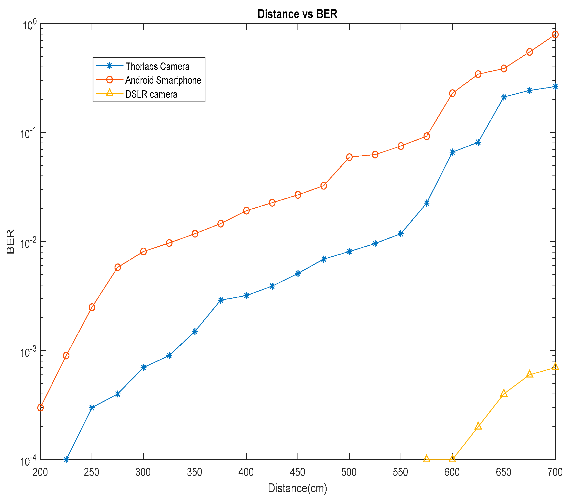
| Link distance | 2.25 m | 1.75 m | 5.5 m |
| Exposure mode | Rolling shutter | Rolling shutter | Rolling shutter |
© 2019 by the authors. Licensee MDPI, Basel, Switzerland. This article is an open access article distributed under the terms and conditions of the Creative Commons Attribution (CC BY) license (http://creativecommons.org/licenses/by/4.0/).
Share and Cite
Aggarwal, G.; Dai, X.; Saatchi, R.; Binns, R.; Sikandar, A. Experimental Demonstration of Single-Channel EEG Signal Using 32 × 32 Pixel OLED Screen and Camera. Electronics 2019, 8, 734. https://doi.org/10.3390/electronics8070734
Aggarwal G, Dai X, Saatchi R, Binns R, Sikandar A. Experimental Demonstration of Single-Channel EEG Signal Using 32 × 32 Pixel OLED Screen and Camera. Electronics. 2019; 8(7):734. https://doi.org/10.3390/electronics8070734
Chicago/Turabian StyleAggarwal, Geetika, Xuewu Dai, Reza Saatchi, Richard Binns, and Ajay Sikandar. 2019. "Experimental Demonstration of Single-Channel EEG Signal Using 32 × 32 Pixel OLED Screen and Camera" Electronics 8, no. 7: 734. https://doi.org/10.3390/electronics8070734
APA StyleAggarwal, G., Dai, X., Saatchi, R., Binns, R., & Sikandar, A. (2019). Experimental Demonstration of Single-Channel EEG Signal Using 32 × 32 Pixel OLED Screen and Camera. Electronics, 8(7), 734. https://doi.org/10.3390/electronics8070734