Review

Recent Advancements in Inertial Micro-Switches

1
College of Mechanical and Electrical Engineering, Chongqing University of Arts and Sciences, Chongqing 402160, China
2
School of Electronic Information Engineering, Yangtze Normal University, Chongqing 408100, China
3
School of Mechanical Engineering, Xi’an Jiaotong University, Xi’an 710049, China
*
Authors to whom correspondence should be addressed.
Electronics 2019, 8(6), 648; https://doi.org/10.3390/electronics8060648
Submission received: 15 April 2019 / Revised: 30 May 2019 / Accepted: 5 June 2019 / Published: 9 June 2019
(This article belongs to the Special Issue Progress in MEMS/NEMS Devices)

Abstract

:
Inertial micro-switches have great potential in the applications of acceleration sensing, due to the integrated advantages of a small size, high integration level, and low or even no power consumption. This paper presents an overview of the recent advancements made in research on the sensitive direction, threshold acceleration, contact effect, and threshold accuracy of inertial micro-switches. The reviewed switches were categorized according to the performance parameters, including multi-directional switches, multi-threshold switches, persistent closed switches, flexible-electrode switches, and low-g high-threshold-accuracy switches. The current challenges and prospects are also discussed.

1. Introduction

Inertial micro-switches, also named threshold accelerometers in earlier times [1,2], have gained considerable attention from academics and industries for decades. The switch works as both a sensor and an actuator, and it is normally open until the applied acceleration is over a given threshold. As such, compared with accelerometers, the switches have the advantages of a simpler structure, high integration level, and low or even no power consumption [3,4]. Furthermore, being superior to accelerometers, the use of inertial micro-switches could avoid the risk of mis-operation caused by electromagnetic noise, since there is no need for constantly powering the switches when monitoring the environment. These features make inertial micro-switches very suitable to be used in early warning or trigger/wakeup-type applications, such as airbags, transportation systems, and geriatric healthcare [5,6,7].
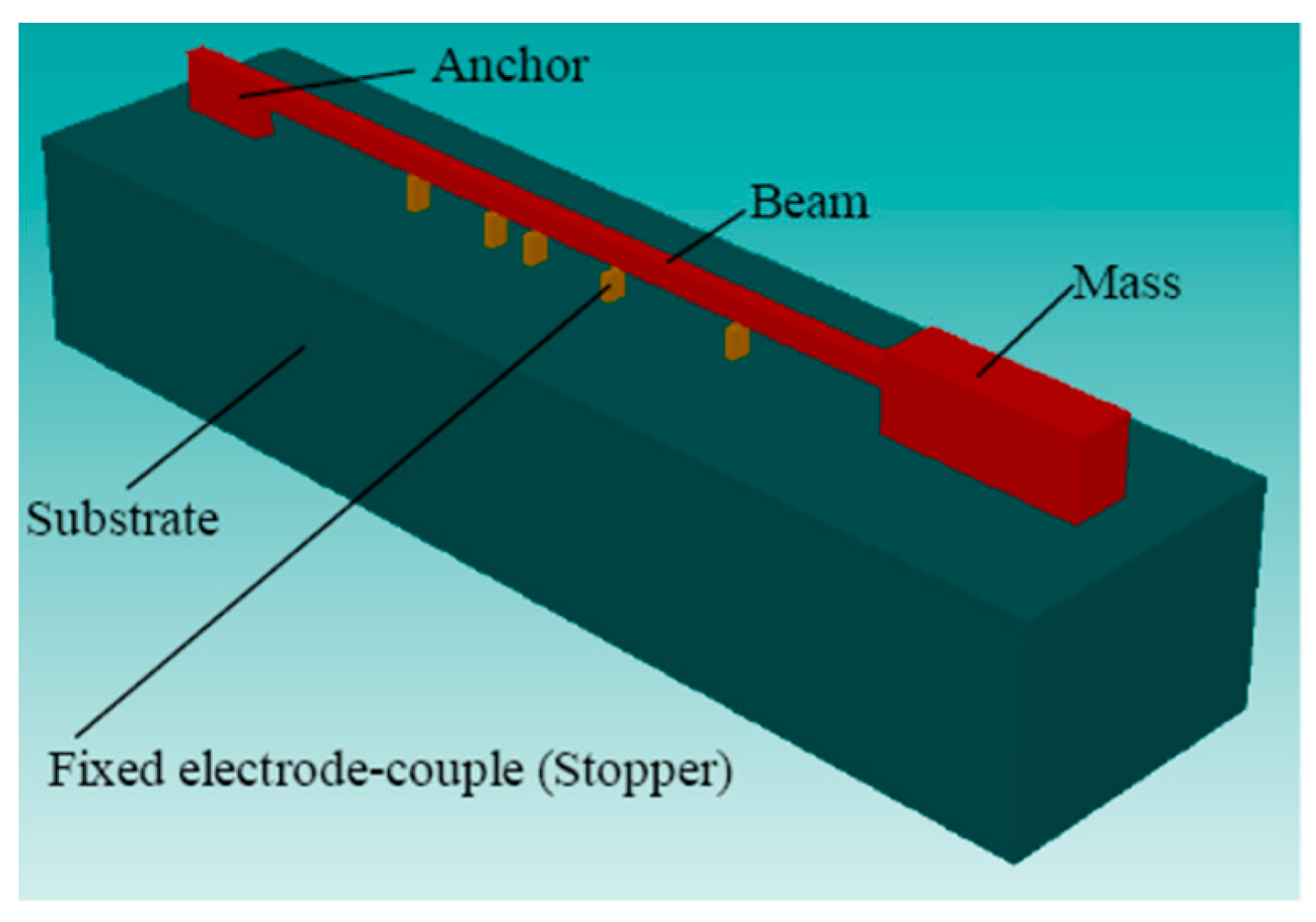
In the conventional design of inertial micro-switches, as shown in Figure 1, a proof mass suspended by springs serving as the movable electrode will contact the fixed electrode on the substrate when an acceleration exceeding the threshold value is applied, turning on the switch and triggering the external circuit. The performance of such a device is mainly evaluated by various of parameters, including the threshold acceleration, threshold accuracy, and contact time. Conventionally, the threshold accuracy of a low-g switch (usually refers to the switch whose threshold is less than 50 g) may be seriously degraded by fabrication errors due to its small feature sizes; a high threshold accuracy is essential to improve the device-to-device threshold uniformity of mass-produced switches, thus facilitating applications; the contact time should be long enough to improve the contact effect of the switch, and such that the turn-on signal can be effectively recognized by the external circuit.
In recent years, benefiting from the rapid development of MEMS technology, there have been various studies on inertial micro-switches with greatly improved performance. In this article, we firstly overview the recent advancements made in studies on the sensitive direction, threshold acceleration, contact effect, and threshold accuracy of inertial micro-switches, and then discuss the current challenges and prospects.

2. Multi-Directional Inertial Micro-Switches

Due to the limitations of process technology, early inertial micro-switches were usually designed with one sensitive direction [1,2,8,9,10]. In recent years, in order to adapt complex application environments, a lot of researchers have focused on multi-directional switches. Since the kind of contact point electrode is widely used, the basic strategy is to arrange electrode pairs (the movable and fixed electrodes) in each sensitive direction.
Typical bi-directional switches were derived from the conventional cantilever-mass structure. For the convenience of processing, they were usually designed to be laterally driven in two opposite directions on the same axis. McNamara et al. [4] arranged the proof mass as a movable electrode and positioned two fixed electrodes on both sides of it, forming two electrode pairs to detect the acceleration in the ±y directions. Based on this design strategy, Currano et al. [11] designed two pairs of a latching mechanism at the end of the proof mass and on the substrate, enabling the switch to remain closed after the end of the acceleration event; Dehkordi et al. [12] made some slots at the end of the proof mass to adjust the rarefied air damping, improving the contact effect. Switches with four sensitive directions are generally activated in two-axis directions. Lin et al. [13] presented a switch with a rhombus contact surface electrode to sense acceleration in the ±x and ±y directions. Furthermore, the movable electrode was suspended in the center of the proof mass by four buffering springs to improve the contact effect.
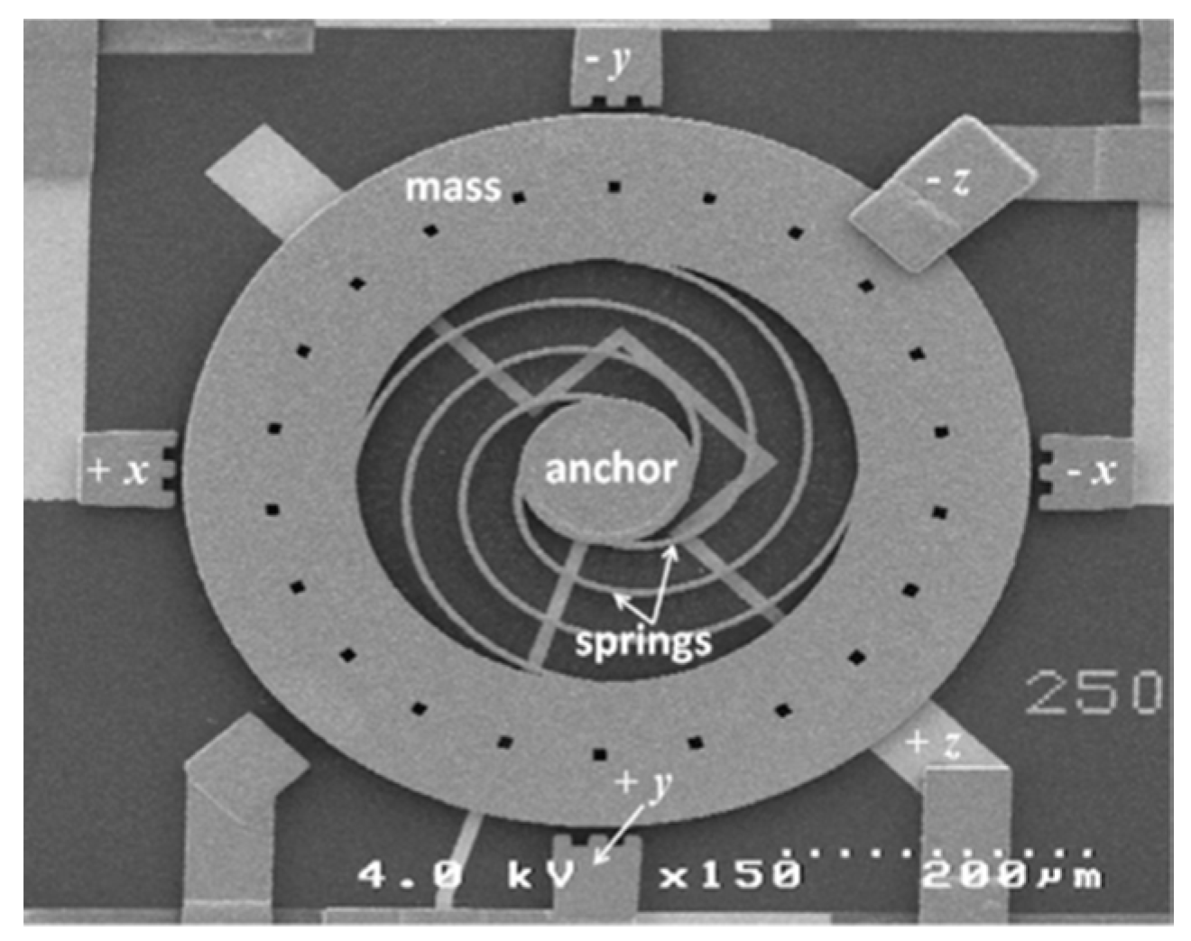
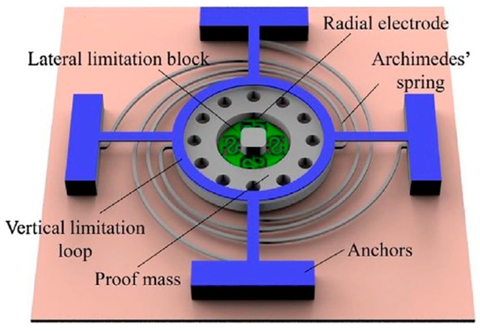
Triaxial sensitive switches were generally designed with a central proof mass serving as the movable electrode suspended by springs, and several fixed electrodes in the XOY plane and vertical direction. The springs may be either inside [3,14] or outside [15,16,17,18] the proof mass, and they are usually compliant in every direction. The sensitive direction is commonly determined by the electrode configuration. Currano et al. [3] proposed a triaxial sensitive switch based on a central annular proof mass suspended by four Archimedes spiral springs, as shown in Figure 2. Six fixed contact-point electrodes were positioned in the ±x, ±y, and ±z directions to detect the applied acceleration in each sensitive direction. Greywall [14] and Sadashi [15] designed the electrode pair with a cylindrical surface to extend the contact area, thus enabling the switch to sense the applied acceleration from any radial directions in the XOY plane. However, due to the single continuous contact surface, it was unable to judge the direction of the applied acceleration. This issue can be addressed by designing discrete flexible electrodes [16,17,18]. Du et al. [16] presented an omni-directional switch with four radial fixed electrodes, as shown in Figure 3. The four electrodes were designed with a spherical surface and suspended by serpentine springs to adapt to the acceleration from any radial directions in the XOY plane. In addition to the similar radial electrode configuration in the XOY plane, Xi et al. [17] positioned an annular axial electrode over the proof mass, enabling the switch to sense acceleration in the hemisphere. Cao et al. [18] developed their hemispheric directional switch with eight cantilever beams positioned symmetrically around the mass serving as the radial electrodes and an annular axial electrode over the mass. The omni-directional sensitivity in the XOY plane was achieved by the deformation of the cantilever beams.
Due to the complex electrode configuration, triaxial sensitive switches were usually fabricated by the multi-layer process of electroplating technology. However, repetitive electroplating processes might cause unexpected fabrication errors, such as dimension variations, an inhomogeneous Young’s modulus, and structural deformation induced by residual stresses between each electroplating layer [3,19,20], leading to a low threshold accuracy of the switch. For example, because of the fabrication errors of the multi-layer process, Currano’s 50 g switch was turned on at 97.5 g acceleration [3].

3. Multi-Threshold Inertial Micro-Switches

Inertial micro-switches with multiple thresholds are essential for some applications, such as portable devices, wherein the space size and power supply are limited, and a wide range of acceleration needs to be detected.
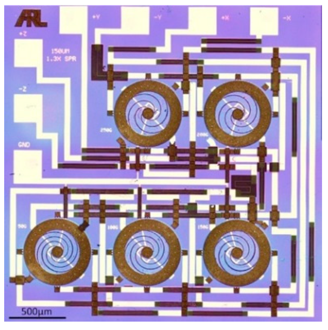
The traditional method to detect multiple thresholds is to integrate multiple switches with different threshold levels on a single chip. In this way, it generally requires an interface circuitry to capture and process the turn-on signal of the switches. Noetze et al. [9] proposed an array of five micro-switches with different dimensions and locations of the proof mass, aiming to obtain different resonance frequencies, acceleration thresholds, and switch-on times. Michaelis et al. [21] developed an additive electroplating MEMS process for the fabrication of an acceleration threshold switch on top of a CMOS (complementary metal oxide semiconductor) signal processing circuit. The traditional sticking problem induced by Au-Au contact was eliminated by using an alloy composition as a coating for the contact electrodes. Selvakumar et al. [10] presented a complete threshold acceleration detection microsystem comprising an array of switches and a CMOS interface circuit. The circuit dissipates less than 300 µW and includes 256 channels. Currano et al. [3] integrated five triaxial switches on a single chip, with each switch designed to close at a different threshold between 50 g and 250 g, as shown in Figure 4. Accordingly, the chip includes 5 thresholds, 6 sensitive directions, and a total of 30 physical switches. In order to simplify the wiring, a resistor ladder connecting each switch together in series was developed, such that the number of pinouts from the chip was substantially reduced to six. In addition to the detection of multiple thresholds, McNamara et al. [4] and Selvakumar et al. [10] designed redundant switches on each threshold level to improve the detection accuracy and fault tolerance. This was achieved by weighting the output signal of the chip on the majority status of these redundant switches. However, the array design strategy will increase the device volume, which is undesirable for some applications. For this reason, Li et al. [22] proposed a multiple-contact switch with two arrays of electrodes based on a single electrostatically driven cantilever, as shown in Figure 5. The two arrays of the movable and fixed electrodes were positioned on the bottom of the beam and on the substrate, respectively, greatly reducing the size of device.
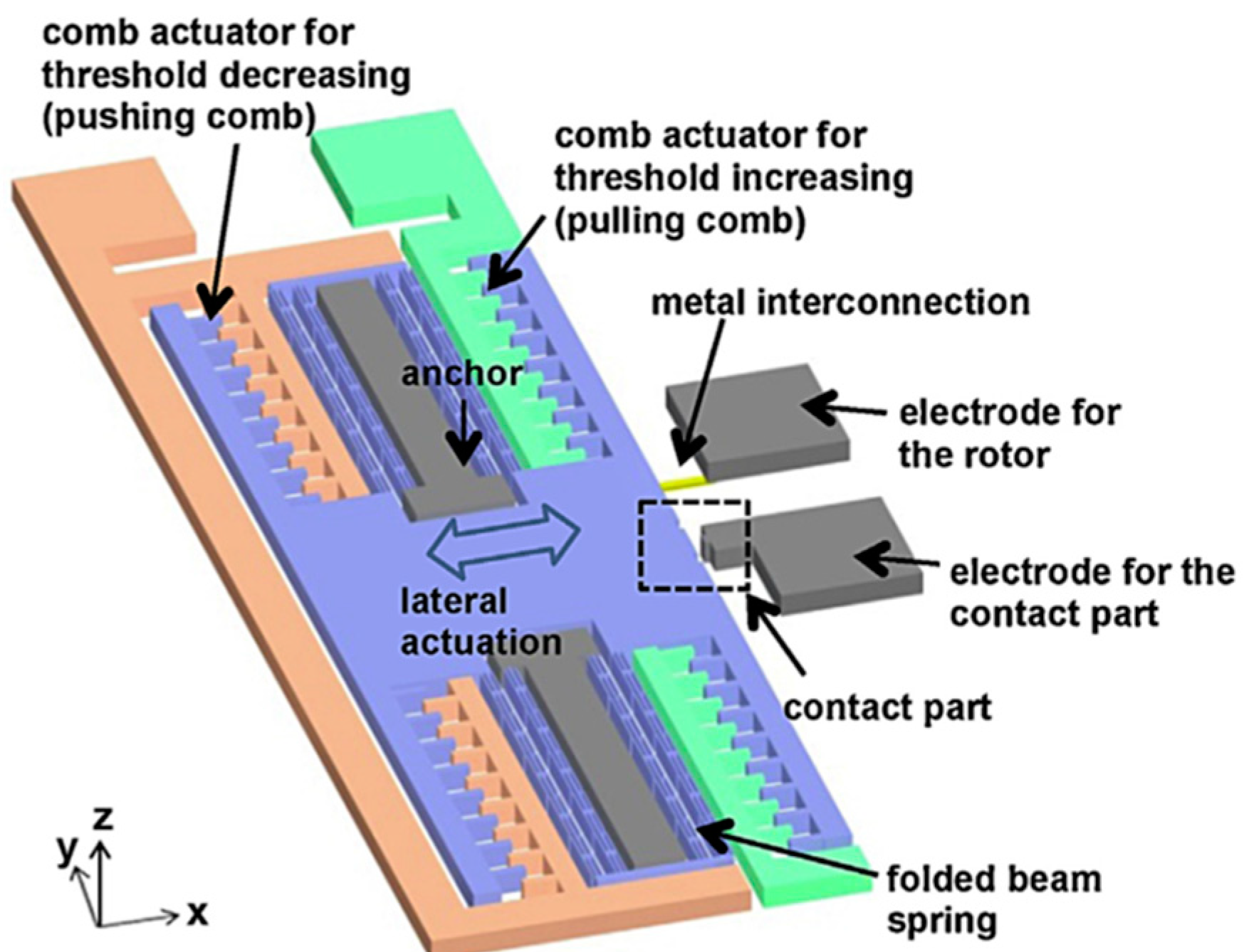
On the other hand, it is an effective way to tune the threshold after fabrication with the aid of electrostatic force. Jia et al. [23] demonstrated a cantilever-type switch with a driving electrode under the cantilever. By applying electrical potential between the driving electrode and the cantilever, an electrostatic force was added to the acceleration force, decreasing the threshold acceleration required to turn the switch on. When the electrical potential increased from 5 to 15 V, the threshold decreased from 2750 to 1900 g. In order to increase the threshold value, Kim et al. [24] proposed a micro-switch incorporating a pair of electrostatic comb actuators. By applying an electrical potential to the two actuators, an electrostatic force was induced on the moving mass, pushing the mass away from the contact part, and therefore increasing the required acceleration to turn the switch on. The threshold value was 11 g without a tuning voltage, and it increased to 30 g when a 30 V voltage was applied. Furthermore, Kim et al. [25] improved the switch with two pairs of electrostatic comb actuators to bi-directionally tune the threshold, as shown in Figure 6. The threshold value at zero tuning voltage was 10.25 g, and the value changed into 2.0 and 17.25 g when the pushing and pulling voltages were both 30 V, respectively. Along with the threshold tunability, a switch of this kind enables threshold compensation for process deviations after device fabrication. In addition, designing the switch on the configuration close the so-called pull-in instability induced by the electrostatic force, wherein the structure collapses toward the electrode at the voltage exceeding a certain critical value, is suggested to improve the sensitivity of the switch for low-g sensing applications [26,27]. On this configuration, even a small additional mechanical shock can result in the ‘on’-state of the switch. Ramini et al. [28] presented an electrostatically actuated switch for low-g seismic applications, enabling the detection of a threshold acceleration as low as 0.02 g.

4. Persistent Closed Inertial Micro-Switches

Even through Si-based switches are convenient for integration with circuits, their contact effect is usually limited by the rigid electrodes. When an acceleration exceeding the threshold is applied to the Si-based switch, its movable rigid electrode bounces intensively after impacting the fixed rigid electrode, resulting in insufficient contact between the two electrodes. The contact time is generally shorter than 10 μs [17,29,30]. In fact, it should be longer than 15 μs, such that the turn-on signal of the switch can be recognized by the external circuit [29]. To address this issue, many researchers have been committed to studying persistent closed switches, wherein the switch remains closed even after the acceleration event is over. Persistent closed switches can be simply classified into three types, such as the latching switches, bistable switches, and micro-fluidic switches, depending on the mechanism which holds the switch in the closed state.
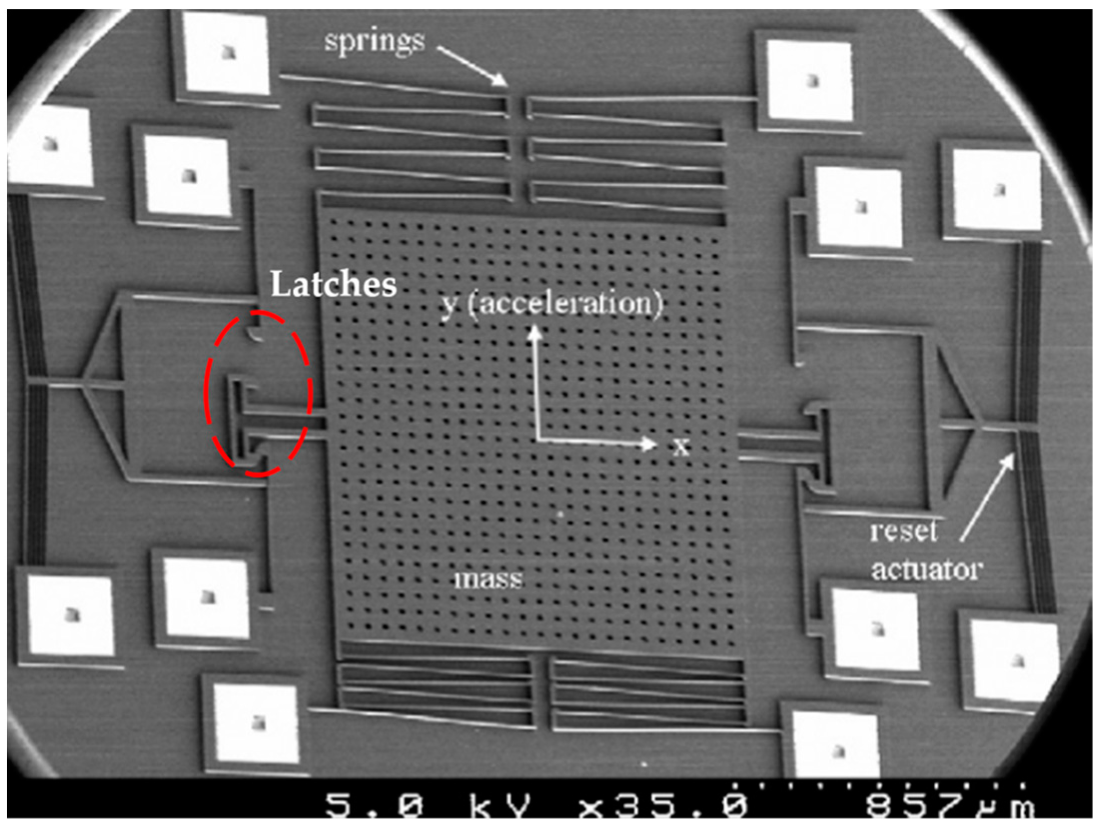
The basic structure of latching switches incorporates a pair of mechanical latches in the sensitive direction, as shown in Figure 7 [31]. The latch with a curved or angled surface is stiff in the sensitive direction of the switch and compliant in the direction perpendicular to the sensitive direction, enabling the switch to remain closed after the end of an acceleration event. Xu et al. [32] studied the energy dissipation of the latching process and concluded that the latches can greatly enhance the shock robustness of the switch compared with hard stops. Ma et al. [33] used various polydimethylsiloxane (PDMS) caps to change the displacement state of the proof mass, thus enabling the adjustment of the acceleration threshold from 40 g to 75 g. Guo et al. [34,35] designed the switch with multi-contacts independent to the proof-mass to prevent the contacts from the impact resulting from the rebound or vibration of the proof-mass once the switch was latched, and therefore the contact reliability was improved. The results showed that the contact resistance was less than 5 Ω while the isolation resistance was more than 200 MΩ, and the maximum allowable current was up to 100 mA. Zhou et al. [36] presented a micro-contact resistance model to investigate the contact performance of the latching switches. As seen in Figure 7, Currano et al. [31] also designed a reset actuator driven by the current to unlatch the switch, although the device size was remarkably increased. In order to achieve a more stable actuation and a facilitated driving, Dellaert et al. [37] presented a thermal actuator that was heated by a polysilicon heater underneath the structure. The designed driver can generate adjustable latching waveforms, which are needed to latch the switch into a closed or open state. In addition, latching switches with multiple pairs of mechanical latches for the detection of multiple acceleration threshold violations were introduced in [38,39].
Bistable switches are usually designed with postbuckling beams based on a complaint mechanism in order to obtain two stable mechanical states, as shown in Figure 8 [40]. When the applied acceleration exceeds the threshold value, the postbuckling beams can quickly snap from one stable state (Figure 8a) to another (Figure 8b), changing the on-off status of the switch. Accordingly, the postbuckling beams and therefore the dynamics of the device system have strong nonlinearity. Zhao et al. [40] presented a computation method for analyzing the nonlinear stiffness of postbuckling beams based on the large deflection buckling theory, and proposed [41] a bistable switch that could sense the threshold acceleration and deceleration, which were 9.7 and −3.1 g based on the experimental results, respectively. Hansen et al. [42] reported a plastic bistable switch fabricated by laser cutting, exhibiting great advantages in fabrication cost and packaging. Gerson et al. [43] proposed an approach to tune the bistability property by passing a current through the suspension and resistive heating the beam material. The experimental results showed that the application of a small tuning current increased the device deflection from 42 to 56 μm. Tanner et al. [44] presented a bistable switch made from a carbon-infiltrated carbon nanotube framework. The results showed that the stress relaxation had no significant effect on the carbon nanotube material, such that the switches had very high repeatability individually. Although the use of the bistable design helps to reduce the effects of friction and wear of the switch, the bistability property is generally complex because there are so many structure parameters that should be considered, such as the post-buckling shape, inertial stress, snapping distance, and the snapping and maintaining forces [45]. Given this consideration, Gao et al. [45] proposed an approach based on the finite element method for the quick design of bistable structures. The required snap-through properties were achieved by adjusting the control parameters, including the position and dimensions of local reinforcements and the compressed length of the beam. The bistable mechanism can also be realized by buckled beams induced by residual stress [46,47,48]. However, it is usually hard to keep the dimension consistency of the residual-stress-induced beams in the MEMS bulk production.
Combining the mechanisms of latching and bistability can enable an extremely low threshold acceleration for inertial micro-switches. A switch of this kind is initially latched on its second stable state, and then snaps back to the first stable state (the initial state after fabrication) when an acceleration exceeding a certain level is applied. The advantages of this design strategy are that the switch can remain in its second stable state under zero load, and the required snap-back acceleration can be much lower than that of the snap-through. Sun et al. [49] presented a latch-bistable switch using two-segment bimorph actuators. The snap-through motion was implemented by applying a DC voltage to heat the bimorph. Krylov et al. [50,51,52] and Medina et al. [53,54,55,56] presented theoretical and experimental investigations on the combination of the mechanical latching and bistability, and established a latching criteria based on an approximate reduced order model. The latching criteria predicted that the latching generally exists in beams of a small designed-initial-elevation to thickness ratio (~0.1) as an axial force is larger than the buckling load [55]. This allowed the design of a device with sufficiently high stiffness in the initial and latched configurations, but with a very low release threshold. Based on this concept, Medina et al. [56] presented a micro-switch with a threshold as low as 0.05 g.
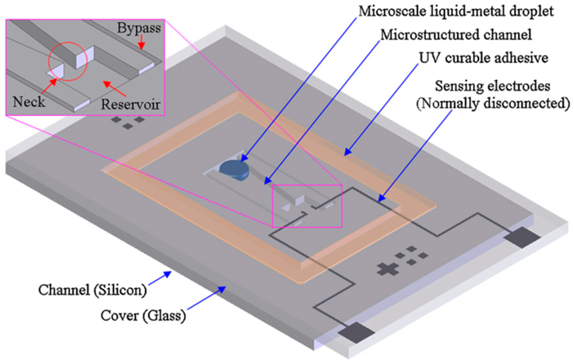
Micro-fluidic switches utilize a micro-liquid-metal droplet as an active component to close the switch under the action of acceleration, as shown in Figure 9 [57]. The objective threshold acceleration can be configured based on the geometry of the micro-structured channel, the wetting property of the channel surface, and the working fluid. The commonly used working fluids are mercury [57,58,59] and Glycerol [60], which have the advantages of a high surface tension, high density, and electrical conduction. Yoo et al. [57] reported that the micro-structured channel can enhance the non-wetting behavior while minimizing the contact angle hysteresis of the micro-droplet on the surface. Moreover, the response time of the device with the micro-structured channel was approximately 33% faster than that of the flat channel. Park et al. [58] fabricated a micro-fluidic switch on a photosensitive glass to uniformly and simultaneously form an anisotropic micro-structured channel during the etching process, providing easy movement of the micro-droplet on the channel surface. Liu et al. [59] investigated the influence of the ambient vibration on the performance of the micro-fluidic switch by applying pulse or sinusoidal interference signals in the X, Y, and Z directions. The results suggested that the performance of the switch was greatly affected by the impact interference signal in the sensitive direction as compared with the low frequency harmonic signal. Huang et al. [60] reported a micro-fluidic switch serving as a time-delay device for safety and arming applications. The results showed that the switch had a 4.1 to 10.9 s delay time by varying the design parameters.

5. Flexible-Electrode Inertial Micro-Switches

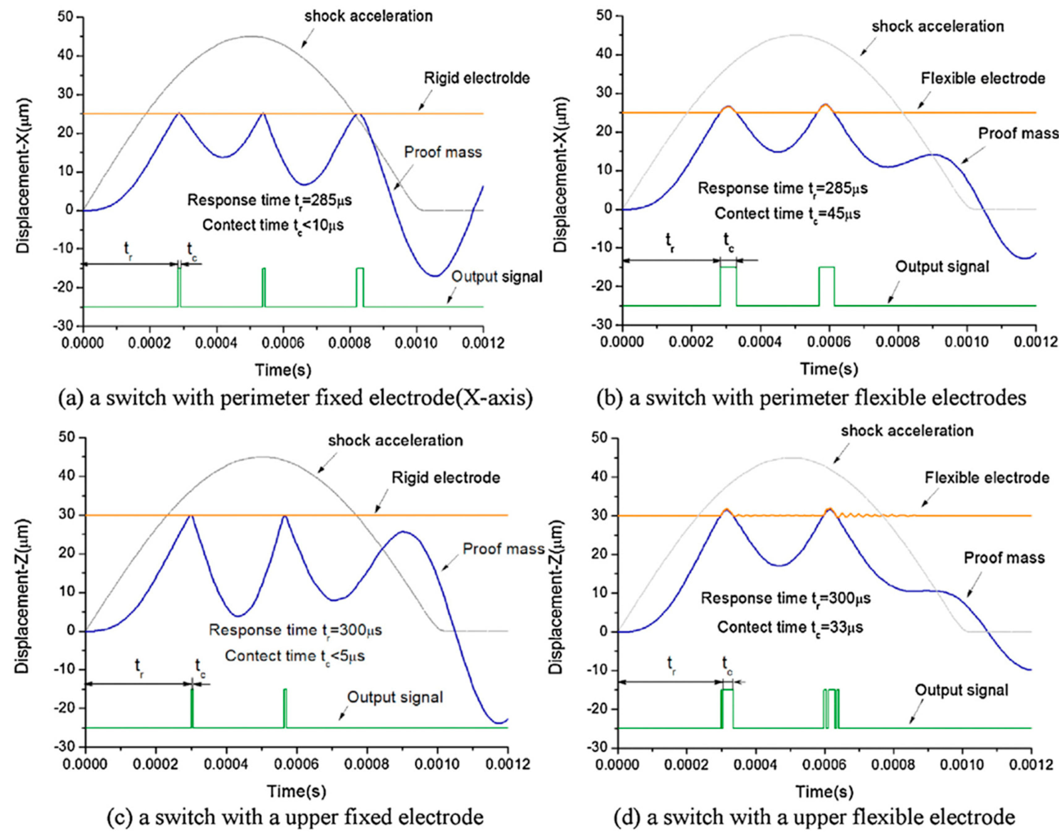
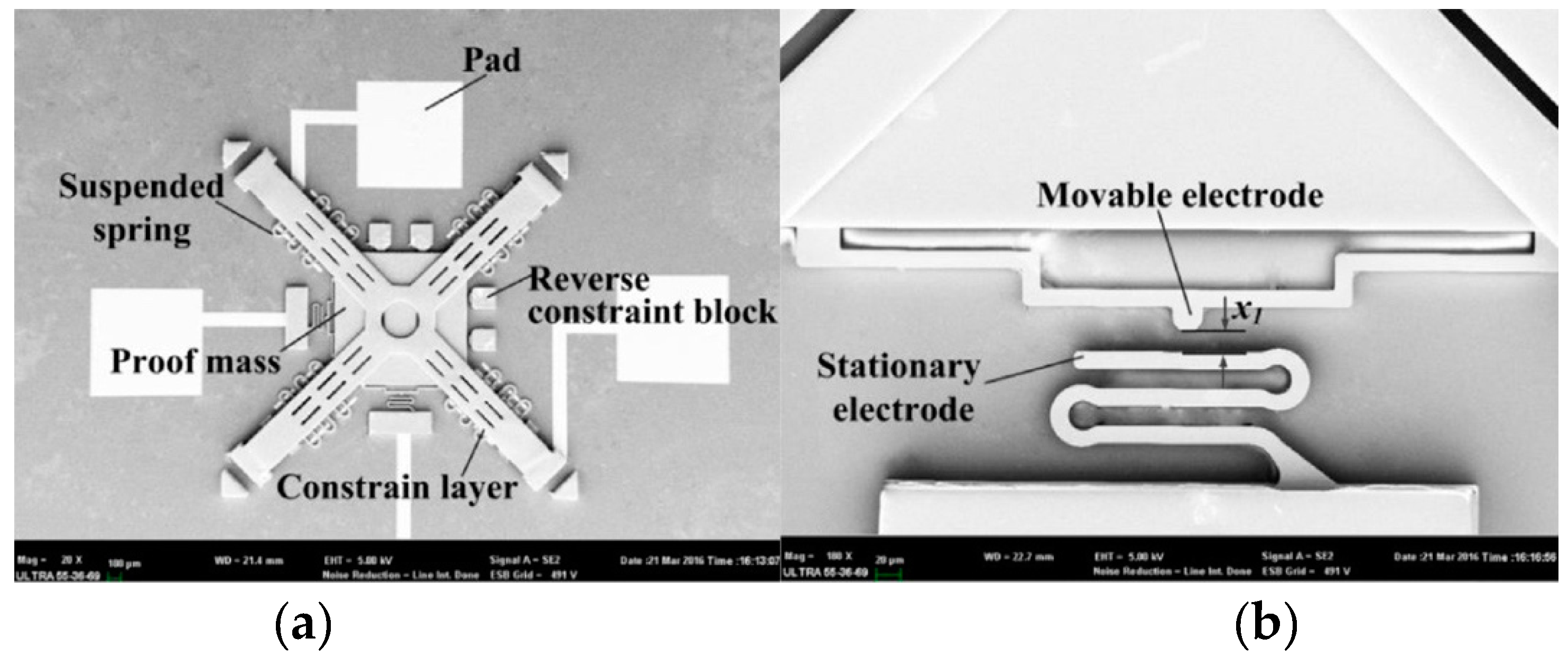
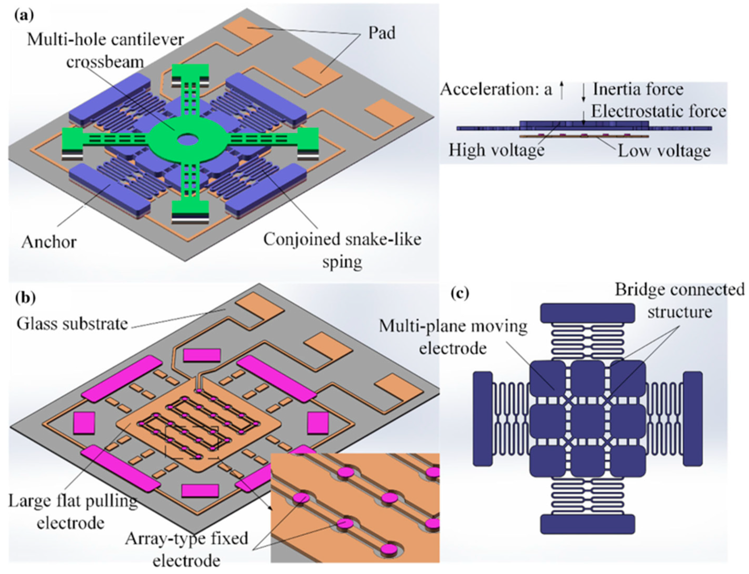
A flexible electrode serving as a buffer mechanism can soften and prolong the contact process of inertial micro-switches, thus improving the contact effect. Flexible-electrode switches are usually fabricated by the multi-layer process of electroplating technology, since the conventional bulk silicon process mainly results in a rigid structure. Furthermore, the electroplated switches commonly have a much lower cost than Si-based switches. Therefore, flexible-electrode switches have been the focus in the recent decade. Yang et al. [61] proposed the first typical and representative inertial micro-switch with a fully clamped multi-hole beam serving as the flexible fixed electrode, although the contact time was only 10 μs. Xi et al. [17] compared the contact effects of flexible and rigid electrodes based on the switch with an axial and four radial flexible electrodes. The results showed that the contact time in the cases of rigid and flexible radial electrodes was less than 10 μs (Figure 10a) and 45 μs (Figure 10b), respectively, and was less than 5 μs (Figure 10c) and 33 μs (Figure 10d) for the cases of rigid and flexible axial electrodes, respectively. Cao et al. [62] investigated the mechanisms of extending the contact time of the flexible electrode using a high-speed camera-based optical measurement system. Xu et al. [63] presented an inertial micro-switch with a flexible movable electrode and a stationary electrode in the double-stair and spring-shape structures, as shown in Figure 11. The unique moveable and fixed electrodes were synchronous follow-up compliant, which can not only extend the contact duration but also reduce the impact bounces. Furthermore, the designed constraint structure can restrain the vibration of the proof mass in the insensitive direction and effectively improve the stability of the device. The experimental results showed that no contact bouncing behavior was observed under the acceleration of 466 g and the contact time was 390 μs. Li et al. [64] proposed an inertial micro-switch with a flexible connecting multi-plane moving electrode and a large flat pulling electrode, as shown in Figure 12. Combined with the electrostatic force assistance, the flexible connecting multi-plane moving electrode can realize the multi-step pulling action to eliminate the rebounding phenomenon and therefore maintain a long contact. The measured contact time was 540 μs. In order to improve the single-axial sensitivity, Yang et al. [65] developed an inertial micro-switch with double layer springs, which could limit the random movement of the proof mass.
Even through the electroplating technology can enable a long contact time of the inertial micro-switches, its inherent fabrication errors as mentioned in Section 2 usually lead to a low threshold accuracy. For instance, in [66], the actual thresholds increased from 32 to 38 g, while the intended target was 38 g, and in [67], the measured threshold of the switch with the designed threshold of 240 g was 288 g. The threshold deviation may be more serious in the case of low-g switches, since a large proof mass and therefore a great number of electroplating processes are required [20,68].

6. Low-g High-Threshold-Accuracy Inertial Micro-Switches

As mentioned in Section 3, it is feasible to compensate for the threshold inaccuracy from the fabrication tolerance by designing redundant switches on the same threshold level [4,10] or adjusting the electrostatic force between the contact parts of the electrostatically actuated switches to tune the threshold [23,24,25]. However, both of the two solutions will inevitably increase the device volume. Furthermore, the electrostatically actuated switches may suffer from electromagnetism interference.
In recent years, two approaches have usually been used to improve the threshold accuracy of the low-g switches: Dimensional compensation and the use of SOI (silicon on insulator) wafers. The dimensional compensation can be carried out after [3,69] or during [16] the fabrication. Field et al. [69] proposed a nonlinear stochastic dynamics model to calibrate the device dimensions based on the experimental results. Because the 2 µm width spring was hard to be accurately processed, Currano et al. [3] modified the spring width of their triaxial switch to 5 µm, and changed the spring length to tune the in-plane (x/y) thresholds to obtain the target acceleration levels. Then, the in-plane threshold values were generally close to the designed values, but the thresholds in the z-axis were much lower than the target levels (~10 to 40 g, as opposed to ~90 to 230 g). Du et al. [16] proposed a method of “thickness compensation” to timely correct the crucial dimensions during the micromachining process based on the sizes of the pre-fabricated structure components. The designed and measured thresholds were 38 g and 35 to 40 g, respectively. Nevertheless, the frequent compensatory steps would lead to a complicated fabrication process.
On the other hand, SOI technology can accurately control the structural thickness, thus reducing the threshold deviation caused by fabrication errors [19,70,71]. Hwang et al. [70] reported a low-g switch based on SOI wafers. The designed and measured threshold values were 6.62 and 6.61 g, respectively. Furthermore, based on the SOI wafer with double buried oxides, the springs can be placed across the central position of the proof mass, improving the contact stability and reliability of the contact electrodes during movement of the proof mass [19,71]. Zhang et al. [71] fabricated a 5 g switch on a double buried-oxide SOI wafer and the measured threshold values ranged from 4.6 to 4.9 g. However, the cost of the SOI wafers have usually been several times higher than common silicon wafers, which may seriously limit their application.

7. Current Challenges and Prospects

In this review, recent progress in inertial micro-switches has been introduced along with the categories of multi-directional switches, multi-threshold switches, persistent closed switches, flexible-electrode switches, and low-g high-threshold-accuracy switches. The study showed that the main performance parameters of inertial micro-switches have been significantly improved in recent years, including the sensitive direction, threshold acceleration, contact effect, and threshold accuracy. However, there are still some remaining critical bottlenecks which need to be overcome for manufacturing on a large scale to occur and applications to be achieved, including:
(i)
The contact effect of the Si-based switches is usually limited by the rigid electrodes. While the persistent closed switches can remain closed after the end of an acceleration pulse, they are usually hard or inconvenient to be reopened, resulting in inconvenience for some applications wherein repeated monitoring is needed.
(ii)
The multi-layer electroplating technology can enable the switch to have multiple sensitive directions or multiple threshold levels by fabricating multi-axial structures, or a reliable contact effect by fabricating flexible structures. However, it usually leads to a low threshold accuracy due to its inherent fabrication errors, especially in the case of low-g switches.
(iii)
While SOI technology can significantly improve the threshold accuracy of the inertial micro-switches, the high cost would hinder its applications.
Despite the bottlenecks, inertial micro-switches have a promising future because of their great potential in the applications of acceleration sensing. In the future, motivated by the application requirements of high performance, the inertial micro-switches should be developed by mainly aiming to achieve a reliable contact effect, multiple sensitive directions and threshold levels, high threshold accuracy, and low cost.

Author Contributions

Y.P., G.L., and T.Z. conceived the presented systematic review idea and the design of the study; Y.S. and G.W. contributed to the acquisition, analysis, and the interpretation of data for the work; Y.P. and Y.S. drafted the paper; G.L., G.W., and T.Z. revised it critically and finally approved the version to be published.

Funding

This research was funded by the Foundation for High-level Talents of Chongqing University of Arts and Sciences (Grant No. 2017RJD15), the Chongqing basic science and frontier technology research project(Grant No. cstc2017jcyjAX0237), the Fundamental Research Funds for the Central Universities (Grant No. xjj2017094), the Natural Science Basic Research Plan in Shaanxi Province of China (Grant No.2018JQ5050), and the Scientific and Technological Research Program of Chongqing Municipal Education Commission (Grant No. KJQN201801329).

Conflicts of Interest

The authors declare no conflict of interest.

References

  1. Frobenius, W.D.; Zeitman, S.A.; White, M.H.; O’Sullivan, D.D. Microminiature ganged threshold accelerometers compatible with integrated circuit technology. IEEE Trans. Electron. Dev. 1972, 19, 37–40. [Google Scholar] [CrossRef]
  2. Loke, Y.; Mckinnon, G.H.; Brett, M.J. Fabrication and characterization of silicon micromachined threshold accelerometers. Sens. Actuators A Phys. 1991, 29, 235–240. [Google Scholar] [CrossRef]
  3. Currano, L.J.; Becker, C.R.; Lunking, D. Triaxial inertial switch with multiple thresholds and resistive ladder readout. Sens. Actuators A Phys. 2013, 195, 191–197. [Google Scholar] [CrossRef]
  4. Mcnamara, S.; Gianchandani, Y.B. LIGA fabricated 19-element threshold accelerometer array. Sens. Actuators A Phys. 2004, 112, 175–183. [Google Scholar] [CrossRef]
  5. Matsunaga, T.; Esashi, M. Acceleration switch with extended holding time using squeeze film effect for side airbag systems. Sens. Actuators A Phys. 2002, 100, 10–17. [Google Scholar] [CrossRef]
  6. Whitley, M.R.; Kranz, M.S.; Kesmodel, R.; Burgett, S.J. Latching Shock Sensors for Health Monitoring and Quality Control. In SPIE—MEMS/MOEMS Components and Their Applications II; International Society for Optics and Photonics: Bellingham, WA, USA, 2005; pp. 185–194. [Google Scholar] [CrossRef]
  7. Ongkodjojo, A.; Tay, F.E.H. Optimized design of a micromachined G-switch based on contactless configuration for health care applications. J. Phys. Conf. Ser. 2006, 34, 1044–1052. [Google Scholar] [CrossRef]
  8. Go, J.S.; Cho, Y.H.; Kwak, B.M. Acceleration Microswitches With Adjustable Snapping Threshold. In Proceedings of the International Solid-State Sensors and Actuators Conference-TRANSDUCERS ‘95, Stockholm, Sweden, 25–29 June 1995; pp. 691–694. [Google Scholar] [CrossRef]
  9. Noetzel, J.; Tønnesen, T.; Benecke, W.; Binder, J.; Mader, G. Quasianalog accelerometer using microswitch array. Sens. Actuators A Phys. 1996, 54, 574–578. [Google Scholar] [CrossRef]
  10. Selvakumar, A.; Yazdi, N.; Najafi, K. A wide-range micromachined threshold accelerometer array and interface circuit. J. Micromech. Microeng. 2001, 11, 118–125. [Google Scholar] [CrossRef]
  11. Currano, L.J.; Yu, M.; Balachandran, B. Latching in a MEMS shock sensor: Modeling and experiments. Sens. Actuators A Phys. 2010, 159, 41–50. [Google Scholar] [CrossRef]
  12. Dehkordi, S.H.; Moghadam, R.A.; Koohsorkhi, J. Design and simulation of bidirectional impact sensors array with optimized air damped response. Microsyst. Technol. 2015, 21, 247–254. [Google Scholar] [CrossRef]
  13. Lin, L.; Zhao, Q.; Yang, Z.; Zhang, D.; Yan, G. Design and simulation of a 2-axis low g acceleration switch with multi-folded beams. In Proceedings of the IEEE International Conference on Solid-state & Integrated Circuit Technology, Guilin, China, 28–31 October 2014. [Google Scholar]
  14. Greywall, D.S. MEMS-Based Inertial Switch. U.S. Patent 7,218,193, 15 May 2007. [Google Scholar]
  15. Sadashi, S. Acceleration Switch. U.S. Patent 8,772,656, 8 July 2014. [Google Scholar]
  16. Du, L.; Li, Y.; Zhao, J.; Wang, W.; Zhao, W.; Zhao, W.; Zhu, H. A low-g MEMS inertial switch with a novel radial electrode for uniform omnidirectional sensitivity. Sens. Actuators A Phys. 2018, 270, 214–222. [Google Scholar] [CrossRef]
  17. Zhanwen, X.; Ping, Z.; Weirong, N.; Liqun, D.; Yun, C. A novel MEMS omnidirectional inertial switch with flexible electrodes. Sens. Actuators A Phys. 2014, 212, 93–101. [Google Scholar] [CrossRef]
  18. Cao, Y.; Xi, Z.; Yu, P.; Wang, J.; Nie, W. A MEMS inertial switch with a single circular mass for universal sensitivity. J. Micromech. Microeng. 2015, 25, 105005. [Google Scholar] [CrossRef]
  19. Zhang, F.; Yuan, M.; Jin, W.; Xiong, Z. Fabrication of a silicon based vertical sensitive low-g inertial micro-switch for linear acceleration sensing. Microsyst. Technol. 2016, 23, 2467–2473. [Google Scholar] [CrossRef]
  20. Du, L.; Ming, Z.; Wang, A.; Chen, S.; Nie, W. Fabrication of novel MEMS inertial switch with six layers on a metal substrate. Microsyst. Technol. 2015, 21, 2025–2032. [Google Scholar] [CrossRef]
  21. Michaelis, S.; Timme, H.J.; Wycisk, M.; Binder, J. Acceleration threshold switches from an additive electroplating mems process. Sens. Actuators A Phys. 2000, 85, 418–423. [Google Scholar] [CrossRef]
  22. Li, K.; Chen, W.Y.; Zhang, W.P. Modeling of Beams’ Multiple-Contact Mode with an Application in the Design of a High-g Threshold Microaccelerometer. Sensors 2011, 11, 5215–5228. [Google Scholar] [CrossRef]
  23. Jia, M.; Li, X.; Song, Z.; Bao, M.; Wang, Y.; Yang, H. Micro-cantilever shocking-acceleration switches with threshold adjusting and ‘on’-state lathing functions. J. Micromech. Microeng. 2007, 17, 567–575. [Google Scholar] [CrossRef]
  24. Kim, H.S.; Jang, Y.H.; Kim, Y.K.; Kim, J.M. MEMS acceleration switch capable of increasing threshold acceleration. Electron. Lett. 2012, 48, 1614–1616. [Google Scholar] [CrossRef]
  25. Kim, H.S.; Jang, Y.H.; Kim, Y.K.; Kim, J.M. MEMS acceleration switch with bi-directionally tunable threshold. Sens. Actuators A Phys. 2014, 208, 120–129. [Google Scholar] [CrossRef]
  26. Younis, M.I.; Alsaleem, F.M.; Miles, R.; Su, Q. Characterization of the performance of capacitive switches activated by mechanical shock. J. Micromech. Microeng. 2007, 17, 1360–1370. [Google Scholar] [CrossRef] [PubMed] [Green Version]
  27. Erez, B.; Stella, L.; Slava, K. Design and implementation of a bistable force/acceleration sensing device considering fabrication tolerances. J. Microelectromech. Syst. 2018, 23, 1–12. [Google Scholar] [CrossRef]
  28. Ramini, A.; Younis, M.I.; Su, Q.T. A low-g electrostatically actuated resonant switch. Smart Mater. Struct. 2013, 22, 025006. [Google Scholar] [CrossRef]
  29. Yang, Z.; Ding, G.; Cai, H.; Xu, X.; Wang, H.; Zhao, X. Analysis and elimination of the ‘skip contact’ phenomenon in an inertial micro-switch for prolonging its contact time. J. Micromech. Microeng. 2009, 19, 045017. [Google Scholar] [CrossRef]
  30. Gerson, Y.; Schreiber, D.; Grau, H.; Krylov, S. Meso scale MEMS inertial switch fabricated using an electroplated metal-on-insulator process. J. Micromech. Microeng. 2014, 24, 405–412. [Google Scholar] [CrossRef]
  31. Currano, L.J.; Bauman, S.; Churaman, W.; Peckerar, M.; Wienke, J.; Kim, S.; Yu, M.; Balachandran, B. Latching ultra-low power mems shock sensors for acceleration monitoring. Sens. Actuators A Phys. 2008, 147, 490–497. [Google Scholar] [CrossRef]
  32. Xu, K.; Zhang, W.; Hao, Y. Mechanical latching stops for reliability improvement of MEMS in shock environments. Microsyst. Technol. 2018, 2, 3399–3407. [Google Scholar] [CrossRef]
  33. Ma, C.W.; Huang, P.C.; Kuo, J.C.; Kuo, W.C.; Yang, Y.J. A novel inertial switch with an adjustable acceleration threshold using an MEMS digital-to-analog converter. Microelectron. Eng. 2013, 110, 374–380. [Google Scholar] [CrossRef]
  34. Guo, Z.Y.; Zhao, Q.C.; Lin, L.T.; Ding, H.T.; Liu, X.S.; Cui, J.; Yang, Z.C.; Xie, H.K.; Yan, G.Z. An acceleration switch with a robust latching mechanism and cylindrical contacts. J. Micromech. Microeng. 2010, 20, 055006. [Google Scholar] [CrossRef]
  35. Guo, Z.Y.; Yang, Z.C.; Lin, L.T.; Zhao, Q.C.; Ding, H.T.; Liu, X.S.; Chi, X.Z.; Cui, J.; Yan, G.Z. Design, fabrication and characterization of a latching acceleration switch with multi-contacts independent to the proof-mass. Sens. Actuators A Phys. 2011, 166, 187–192. [Google Scholar] [CrossRef]
  36. Zhou, Z.J.; Nie, W.R.; Xi, Z.W.; Wang, X.F. Electrical contact performance of MEMS acceleration switch fabricated by UV-LIGA technology. Microsyst. Technol. 2015, 21, 2271–2278. [Google Scholar] [CrossRef]
  37. Dellaert, D.; Doutreloigne, J. A thermally-actuated latching MEMS switch matrix and driver chip for an automated distribution frame. Mechatronics 2016, 40, 287–292. [Google Scholar] [CrossRef]
  38. Sun, X.Q.; Zhou, S.; Carr, W.N. A surface micromachined latching accelerometer. In Proceedings of the International Solid State Sensors and Actuators Conference, Chicago, IL, USA, 19 June 1997; pp. 1189–1192. [Google Scholar] [CrossRef]
  39. Mehner, H.; Weise, C.; Schwebke, S.; Hampl, S.; Hoffmann, M. A passive microsystem for detecting multiple acceleration events beyond a threshold. Microelectron. Eng. 2015, 145, 104–111. [Google Scholar] [CrossRef]
  40. Zhao, J.; Jia, J.; Wang, H.; Li, W. A novel threshold accelerometer with postbuckling structures for airbag restraint systems. IEEE Sens. J. 2007, 7, 1102–1109. [Google Scholar] [CrossRef]
  41. Zhao, J.; Yang, Y.; Fan, K.; Hu, P.; Wang, H. A bistable threshold accelerometer with fully compliant clamped-clamped mechanism. IEEE Sens. J. 2010, 10, 1019–1024. [Google Scholar] [CrossRef]
  42. Hansen, B.J.; Carron, C.J.; Jensen, B.D.; Hawkins, A.R.; Schultz, S.M. Plastic latching accelerometer based on bistable compliant mechanisms. Smart Mater. Struct. 2007, 16, 1967–1972. [Google Scholar] [CrossRef]
  43. Gerson, Y.; Krylov, S.; Ilic, B. Electrothermal bistability tuning in a large displacement micro actuator. J. Micromech. Microeng. 2010, 20, 112001. [Google Scholar] [CrossRef]
  44. Tanner, J.D.; Jensen, B.D. Power-free bistable threshold accelerometer made from a carbon nanotube framework. Mech. Sci. 2013, 4, 397–405. [Google Scholar] [CrossRef] [Green Version]
  45. Gao, R.J.; Li, M.L.; Wang, Q.; Zhao, J.; Liu, S.T. A novel design method of bistable structures with required snap-through properties. Sens. Actuators A Phys. 2018, 272, 295–300. [Google Scholar] [CrossRef]
  46. Go, J.S.; Cho, Y.H.; Kwak, B.M. Snapping microswitches with adjustable acceleration threshold. Sens. Actuators A Phys. 1996, 54, 579–583. [Google Scholar] [CrossRef]
  47. Freudenreich, M.; Mescheder, U.; Somogyi, G. Simulation and realization of a novel micromechanical bi-stable switch. Sens. Actuators A Phys. 2004, 114, 451–459. [Google Scholar] [CrossRef]
  48. Sulfridge, M.; Saif, T.; Miller, N.; Meinhart, M. Nonlinear dynamic study of a bistable MEMS: Model and experiments. J. Microelectromech. Syst. 2004, 13, 725–731. [Google Scholar] [CrossRef]
  49. Sun, X.Q.; Farmer, K.R.; Carr, W.N. A bistable microrelay based on two-segment multimorph cantilever actuators. In Proceedings of the Eleventh Annual International Workshop on Micro Electro Mechanical Systems (MEMS 98. IEEE), Heidelberg, Germany, 25–29 January 1998; pp. 154–159. [Google Scholar] [CrossRef]
  50. Krylov, S.; Ilic, B.R.; Schreiber, D.; Seretensky, S.; Craighead, H. The pull-in behavior of electrostatically actuated bistable microstructures. J. Micromech. Microeng. 2008, 18, 55026. [Google Scholar] [CrossRef]
  51. Krylov, S.; Dick, N. Dynamic stability of electrostatically actuated initially curved shallow micro beams. Contin. Mech. Thermodyn. 2010, 22, 445–468. [Google Scholar] [CrossRef]
  52. Krylov, S.; Ilic, B.R.; Lulinsky, S. Bistability of curved microbeams actuated by fringing electrostatic fields. Nonlinear Dyn. 2011, 66, 403–426. [Google Scholar] [CrossRef]
  53. Medina, L.; Gilat, R.; Krylov, S. Symmetry breaking in an initially curved micro beam loaded by a distributed electrostatic force. Int. J. Solids Struct. 2012, 49, 1864–1876. [Google Scholar] [CrossRef] [Green Version]
  54. Medina, L.; Gilat, R.; Ilic, B.; Krylov, S. Experimental investigation of the snap-through buckling of electrostatically actuated initially curved pre-stressed micro beams. Sens. Actuators A Phys. 2014, 220, 323–332. [Google Scholar] [CrossRef]
  55. Medina, L.; Gilat, R.; Krylov, S. Latching in bistable electrostatically actuated curved micro beams. Int. J. Eng. Sci. 2017, 110, 15–34. [Google Scholar] [CrossRef]
  56. Medina, L.; Gilat, R.; Krylov, S. Sub g Threshold Acceleration Sensor Incorporating Latched Bistable Beam. In Proceedings of the ASME 2018 International Design Engineering Technical Conferences and Computers and Information in Engineering Conference, Quebec City, QC, Canada, 26–29 August 2018. [Google Scholar] [CrossRef]
  57. Yoo, K.; Park, U.; Kim, J. Development and characterization of a novel configurable MEMS inertial switch using a microscale liquid-metal droplet in a microstructured channel. Sens. Actuator A Phys. 2011, 166, 234–240. [Google Scholar] [CrossRef]
  58. Park, U.; Yoo, K.; Kim, J. Development of a mems digital accelerometer (MDA) using a microscale liquid metal droplet in a microstructured photosensitive glass channel. Sens. Actuators A Phys. 2010, 159, 51–57. [Google Scholar] [CrossRef]
  59. Liu, T.; Wei, S.; Tao, Y.; Yuan, X. Vibration interference analysis and verification of micro-fluidic inertial switch. AIP Adv. 2014, 4, 32–33. [Google Scholar] [CrossRef]
  60. Huang, Y.C.; Sung, W.L.; Lai, W.C.; Liu, C.Y.; Fang, W. Design and implementation of time-delay switch triggered by inertia load. In Proceedings of the IEEE 26th International Conference on Micro Electro Mechanical Systems, Taiwan, China, 20–24 January 2013; pp. 729–732. [Google Scholar] [CrossRef]
  61. Yang, Z.; Ding, G.; Chen, W.; Fu, S.; Sun, X.; Zhao, X. Design, simulation and characterization of an inertia micro-switch fabricated by non-silicon surface micromachining. J. Micromech. Microeng. 2007, 17, 1598–1604. [Google Scholar] [CrossRef]
  62. Cao, Y.; Xi, Z.; Yu, P.; Wang, J.; Nie, W. Optical Measurement of the Dynamic Contact Process of a MEMS Inertial Switch Under High Shock Loads. IEEE Trans. Ind. Electron. 2017, 64, 701–709. [Google Scholar] [CrossRef]
  63. Xu, Q.; Sun, B.; Li, Y.; Xiang, X.; Lai, L.; Li, J.; Ding, G.; Zhao, X.; Yang, Z. Design and characterization of an inertial microswitch with synchronous follow-up flexible compliant electrodes capable of extending contact duration. Sens. Actuators A Phys. 2018, 270, 34–45. [Google Scholar] [CrossRef]
  64. Li, J.; Wang, Y.; Li, Y.; Fu, B.; Sun, Y.; Yao, J.; Ding, G.; Zhao, X.; Yang, Z. A contact-enhanced MEMS inertial switch with electrostatic force assistance and multi-step pulling action for prolonging contact time. Microsyst. Technol. 2018, 24, 3179–3191. [Google Scholar] [CrossRef]
  65. Zhuoqing, Y.; Jianhao, S.; Jinyuan, Y.; Xiaojing, Z.; Guifu, D.; Xiaolin, Z. A laterally-driven mems inertial switch with double layers suspended springs for improving single-axis sensitivity. IEEE Trans. Compon. Packag. Manuf. Technol. 2018, 8, 1845–1854. [Google Scholar] [CrossRef]
  66. Chen, W.G.; Wang, Y.L.; Zhang, Y.H.; Cheng, P.; Wang, Y.; Ding, G.F.; Zhao, X.L.; Yang, Z.Q. Fabrication of a novel contact-enhanced horizontal sensitive inertial micro-switch with electroplating nickel. Microelectron. Eng. 2014, 127, 21–27. [Google Scholar] [CrossRef]
  67. Xu, Q.; Yang, Z.; Fu, B.; Li, J.; Zhao, X. A surface-micromachining-based inertial micro-switch with compliant cantilever beam as movable electrode for enduring high shock and prolonging contact time. Appl. Surf. Sci. 2016, 387, 569–580. [Google Scholar] [CrossRef]
  68. Peng, Y.C.; Wu, G.G.; Pan, C.P.; Lv, C.; Luo, T.H. A 5 g inertial micro-switch with enhanced threshold accuracy using squeeze-film damping. Micromachines 2018, 9, 539. [Google Scholar] [CrossRef]
  69. Field, R.V.; Epp, D.S. Development and calibration of a stochastic dynamics model for the design of a MEMS inertial switch. Sens. Actuators A Phys. 2007, 134, 109–118. [Google Scholar] [CrossRef]
  70. Hwang, J.; Ryu, D.; Park, C.; Jang, S.G.; Lee, C.I.; Kim, Y.K. Design and fabrication of a silicon-based MEMS acceleration switch working lower than 10 g. J. Micromech. Microeng. 2017, 27, 065009. [Google Scholar] [CrossRef]
  71. Zhang, F.; Wang, C.; Yuan, M.; Tang, B.; Xiong, Z. Conception, fabrication and characterization of a silicon-based MEMS inertial switch with a threshold value of 5 g. J. Micromech. Microeng. 2017, 27, 125001. [Google Scholar] [CrossRef]
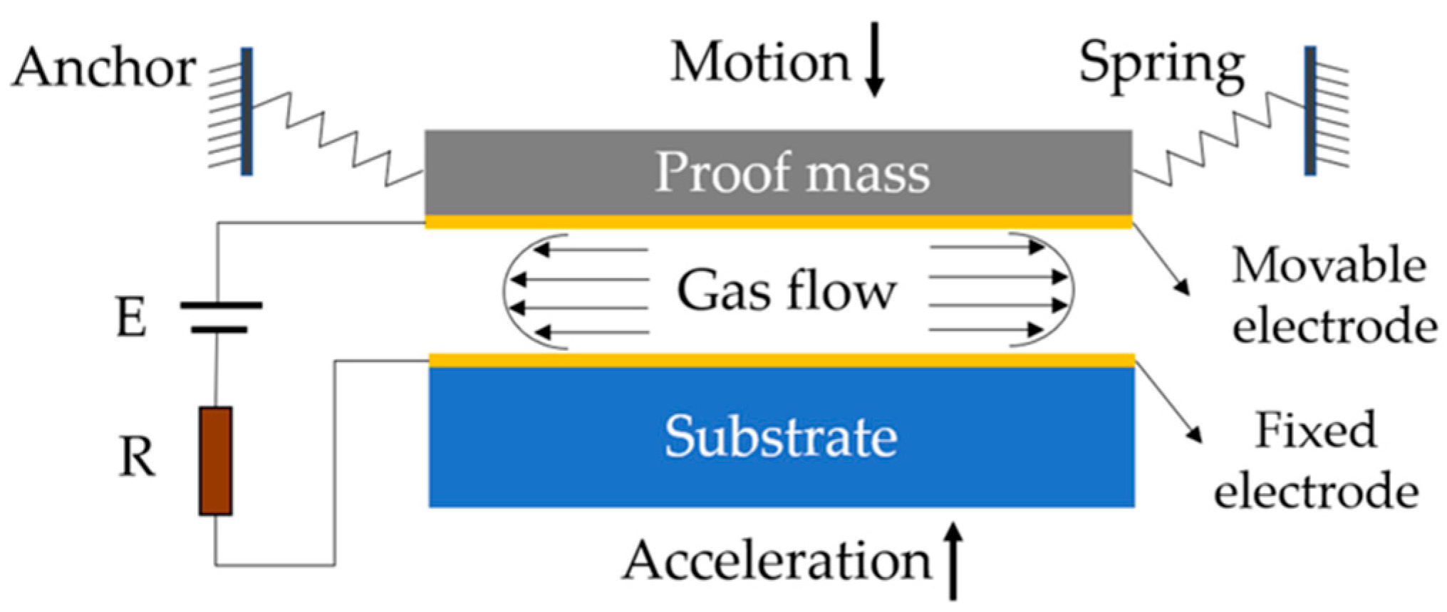
Figure 1. Basic model of a conventional inertial micro-switch.
Electronics 08 00648 g001
Figure 2. A switch with six fixed contact-point electrodes positioned in the ±x, ±y, and ±z directions for triaxial sensitivity [3].
Electronics 08 00648 g002
Figure 3. An omni-directional switch with four radial fixed electrodes for the detection of acceleration from any radial directions in the XOY plane [16].
Electronics 08 00648 g003
Figure 4. Full chip with five triaxial switches and a resistor ladder [3].
Electronics 08 00648 g004
Figure 5. A multiple-contact switch based on a single electrostatically driven cantilever [22].
Electronics 08 00648 g005
Figure 6. A switch with comb driving actuators as a mechanism of threshold tuning for threshold bi-directional tunability [25].
Electronics 08 00648 g006
Figure 7. A switch with mechanical latches and reset actuators in the sensitive directions [31].
Electronics 08 00648 g007
Figure 8. Postbuckling beams structure. (a) Original state. (b) Postbuckling state [40].
Electronics 08 00648 g008
Figure 9. Scheme of a micro-fluidic switch [57].
Electronics 08 00648 g009
Figure 10. Simulated displacement–time curves of the proof mass in the switch under accelerations in the radial and axial direction. (a) A switch with rigid perimeter electrodes. (b) A switch with flexible perimeter electrodes. (c) A switch with a rigid upper electrode. (d) A switch with a flexible upper electrode [17].
Electronics 08 00648 g010
Figure 11. SEM images of (a) an inertial micro-switch with a flexible movable electrode and a stationary electrode in the double-stair and spring-shape structures, and (b) the close-ups of synchronous follow-up compliant electrodes [63].
Electronics 08 00648 g011
Figure 12. (a) Sketch of an electrostatic force-assisted contact-enhanced MEMS (micro-electro-mechanical system) inertial switch. (b) Schematic of the array-type fixed electrode and pulling electrode, and (c) top view of the moving electrode [64].
Electronics 08 00648 g012