Abstract
A high-speed, low-power divide-by-3/4 prescaler based on an extended true single-phase clock D-flip flop (E-TSPC DFF) is presented. We added two more transistors and a mode control signal to the conventional E-TSPC based divide-by-4 divider to achieve the function of the divide-by-3/4 dual modulus frequency divider. The designed divide-by-3/4 achieved higher speed and lower power operation with mode control compared with the conventional ones. The prescaler was comprised of sixteen transistors and integrates an inverter in the second DFF to provide output directly. The power consumption was minimized due to the reduced number of stages and transistors. In addition, the prescaler operating speed was also improved due to a reduced critical path. We compared the simulation results with conventional E-TSPC based divide-by-3/4 dividers in the same process, where the figure-of-merit (FoM) of the proposed divider was 17.4–75.5% better than conventional ones. We have also fabricated the prescaler in a 40 nm complementary metal oxide semiconductor (CMOS) process. The measured highest operating frequency was 9 GHz with 0.303 mW power consumption under 1.35 V power supply, which agrees with the simulation well. The measurement results demonstrate that the proposed divider achieves high-speed and low-power operation.
1. Introduction
With the rapid development of coherent wireless communication systems, frequency synthesizers become indispensable. Internet of things (IoT) applications [1,2,3], for example, will be ubiquitous in the near future and integrate into our daily life.
IoT applications put unprecedented challenges on cost and battery size for IoT sensor nodes [4], in which phase-locked-loop (PLL) synthesizers play a key role in terms of performance as well as power consumption. Within PLL synthesizers, the high-speed divider is a power-hungry block, which transforms a high-frequency input signal into a relatively low one for the following stages. In particular, the prescaler inside dividers often operates at the highest frequency and determines the operating frequency and power consumption of frequency dividers. For example, a divider which transforms a 4 GHz signal into a 40 MHz signal, a divide-by-4 prescaler could consume more than 50% power consumption of the entire divider. Conventionally, dividers with a division ratio of 2/3, 4/5 or larger ratios are usually implemented for prescalers. However, a divider with a 3/4 division ratio is favorable in some cases, such as 7–9 division, as shown in Figure 1. A divide-by-2/3 prescaler or a divide-by-3/4 prescaler consists of two DFFs and some other logic to control the divide ratios. The output frequency of a divide-by-2/3 prescaler is higher than a divide-by-3/4 prescaler. If we use only one divider as a prescaler, the back-stage circuit of a divide-by-2/3 prescaler needs to process a higher frequency signal which is harder to design the back stages. A divide-by-4/5 prescaler usually consists of three or four DFFs. The extra DFFs lead to extra power consumption. However, there are few pieces of research about divide-by-3/4 prescalers. Study about divide-by-3/4 prescaler is valuable.
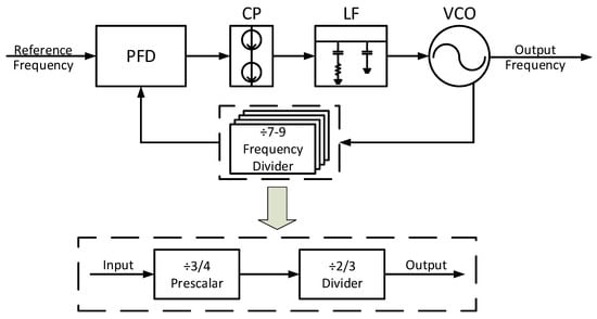
Figure 1.
Block diagram of the proposed phase-locked-loop (PLL) synthesizer.
There are several techniques to realize prescalers, including injection-locked frequency dividers [5,6,7], True single-phase clock (TSPC) D-flip flop (DFF) based dividers [8,9,10,11] and true single phase clock (E-TSPC) DFF based dividers [12,13]. In this paper, an E-TSPC DFF based prescaler implementation was chosen due to its higher operating frequencies than TSPC ones and lower power consumption than injection-locked ones with a small chip area. In Section 2, we introduce different structures of divider circuits and compare the architecture of the proposed prescaler with different topologies of divide-by-3/4 prescalers based on E-TSPC DFF. Section 3 shows the simulation and measurement results in a 40 nm CMOS process and comparison with several state-of-the-art E-TSPC based prescalers. Section 4 concludes the paper.
2. High-Speed E-TSPC Based Divide-by-3/4 Frequency Divider
2.1. Comparaison of Different Frequency Divider Structures
A frequency divider is a basic block of PLL synthesizers, which usually follows a voltage controlled oscillator (VCO) to slow down its signals to a low-frequency one that CMOS logic can process. Since a frequency divider often operates at the highest frequency of synthesizers, it significantly impacts their power consumption and phase noise performance. These three different types of high-speed frequency divider are usually used—injection locked frequency dividers (ILFD), static frequency dividers such as current mode logic (CML) and TSPC logic based dividers, and dynamic frequency dividers such as extended E-TSPC logic based dividers. Table 1 shows the comparison of speed and power consumption of these different structures.

Table 1.
Performance of different structures of frequency divider.
CML based divider leverages differential architecture and small signal swing to achieve high-speed operation. However, it induces a large power consumption due to a doubled number of operating transistors and DC power consumption. In addition, a CML based divider often features constant power consumption with controlled bias currents, resulting in a complicated design. Since CML belongs to static logic, CML based divider can operate from DC to a high-frequency.
In order to boost operating frequency, people use ILFD architecture exploiting inductive loads to compensate parasitic capacitance and achieve a high-speed division. An ILFD could perform division at a higher than 200 GHz frequency [14]. However, ILFD mandates a sophisticated design and occupies a large chip area due to its inductive loads, which introduces frequency selectivity and limits its operating frequency range. Therefore, an ILFD is not optimum to cost-sensitive IoT applications.
In contrast, a TSPC frequency divider features a simple structure with only transistors, which substantially reduces power consumption and chip area. It is also forward to implement programmable dividing ratios in TSPC DFF. Although the maximum operating frequency of TSPC dividers is lower than its ILFD counterpart due to lack of inductive load, and is also inferior to CML based divider because of its large voltage swing, TSPC based dividers present much better power consumption with smaller chip area at relatively low operating frequencies than ILFD based and CML based dividers. Given most of IoT applications operate at low RF frequencies, TSPC based dividers are preferred. It is worth noting that TSPC based dividers belong to dynamic dividers and have a maximum operating frequency as well as a minimum operating frequency instead of DC.
E-TSPC divider is an extended version of TSPC divider, which consists of six transistors without an output buffer. Compared to conventional TSPC divider with at least nine transistors, it reduces the transistor count by 33%. Therefore, an E-TSPC DFF divider can achieve high-speed operation with low power consumption, wide operating frequency range, and small chip area at the cost of higher minimum operating frequency. Consequently, an E-TSPC DFF based dual-modulus prescaler can also achieve low power, a small area with CMOS output swing. Moreover, E-TSPC DFFs are compatible with not-or (NOR) or not-and (NAND) logic by simply adding one transistor at input stages, which facilitates programmable divider design. Therefore, E-TSPC DFF based prescaler was chosen to implement the design in this paper.
2.2. Conventional E-TSPC Based Divide-by-3/4 Frequency Dividers
There are two conventional topologies and a modified topology [12] of divide-by-3/4 frequency dividers based on E-TSPC DFFs in prior arts.
The first divide-by-3/4 frequency divider is based on two NOR gates, as shown in Figure 2a. Since the divider only needs the output QN from the first DFF stage, we can annihilate an inverter in the first DFF stage that is redundant. In addition, this divider presents a critical path from Qn2 to D2 passing through two NOR gates. These extra gates in the path obviously slow down the operating speed of the prescaler. One approach to improve the speed is to combine the logic gates with the DFFs, which, however, still presents the speed bottleneck of this topology with a long path.
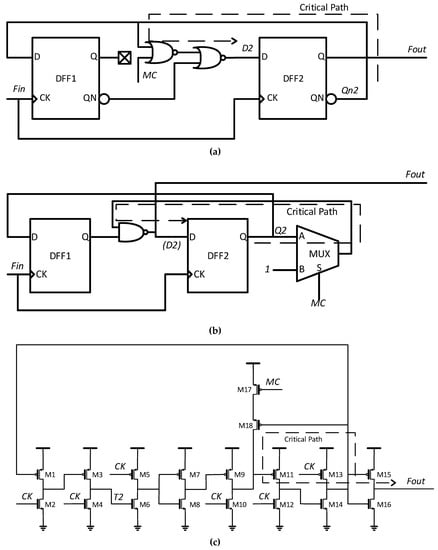
Figure 2.
Conventional divide-by-3/4 divider prescalers (a) not-or(NOR)-based prescaler; (b) multiplex(MUX)-based prescaler; (c) prescaler presented in Reference [12].
The second divider-by-3/4 is based on multiplex (MUX) gates, as shown in Figure 2b. This divider uses one MUX gate and one NAND gate to implement mode control. The MUX based divider can be simplified by a full 2-transistor and a single PMOS transmission gate which could have similar parasitic to the NOR-based one.
There is a modified divider-by-3/4 proposed in Reference [12], as shown in Figure 2c. This divider replaces conventional logic gates with two transistors to control the division mode. By doing so, its performance in divide-by-4 mode is improved because there are no redundant transistors between the two DFFs, otherwise, the signal has to go through extra gates in the dividers in Figure 2a,b. In divide-by-3 mode, the added transistors of this topology must charge quickly to support high-speed operation and lead to high current consumption.
2.3. The Proposed Divide-by-3/4 Frequency Divider
The performance FoM of a prescaler can be defined as the ratio of its maximum operating speed over its power consumption. The maximum operating frequency is usually dominated by the divide-by-3 mode because there is a longer critical path. Therefore, an efficient approach to improve the speed is to reduce the critical path of the divider in the divide-by-3 mode.
Conventional divide-by-3/4 prescalers add common logic gates between two DFFs. To avoid this, we minimize the path by building a new connection instead of the logic gates between the two DFFs. The proposed divide-by-3/4 prescaler based on E-TSPC DFFs is shown in Figure 3. We use 16 transistors including the output inverter in total, compared with 18 transistors in Reference [12]. Most importantly, we employ two N metal oxide semiconductor (NMOS) transistors to constitute the critical path from node T2 to node T5 and cut down the current consumption. As shown in Figure 3, transistors M1–M6 form the first DFF stage, transistors M7–M14 form the second DFF stage, and transistors M15 and M16 form the mode control switch. The sizes of the transistors are optimized to balance the speed and power consumption. Especially for node T5, to realize the switch of the divide ratio, M9, M10, M15 and M16 are designed to have different driving abilities.
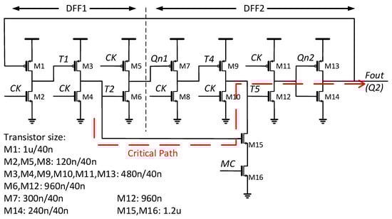
Figure 3.
Proposed divide-by-3/4 frequency divider.
As shown in Figure 3, the delay of the critical path from node T2 to T5 is minimized because the NMOS transistor M15 essentially connects node T2 with node T5. In addition, there are only two driving transistors from node T5 to the output. Compared with the conventional prescalers, our proposed prescaler reduces the critical path delay by almost 30%.
Reference [11] suggests that the total power consumption of a divider is determined by its switching power and short circuit power consumption. The switching power consumption is given by
where N is the number of stages, is the input clock frequency, is the load capacitance, and is the supply voltage.
The short circuit power consumption is given by
where is the short circuit current. Since the switching power consumption increases with the operating frequency, it dominates the total power consumption at a high operating frequency. To implement a low-power prescaler, we must reduce the value of , N and supply voltage .
The proposed prescaler consists of two E-TSPC DFFs with no redundant circuits. The additional load capacitance of node T2 and T5 is and , respectively. Therefore, the power consumption is much lower than that of conventional topologies and is also lower than that in [12] because of the reduction of an inverter in the first DFF.
We can control the prescaler in either a divide-by-3 or divide-by-4 mode by setting the Mode-Control (MC) signal. When MC is low to turn off NMOS transistor M16, the added route is deactivated. The two DFFs are in series and operate in divide-by-4 mode. The influence of the additional two transistors is negligible. Because we reduce the extra transistors between the two DFFs, the proposed prescaler demonstrates a higher speed and lower power consumption than conventional ones.
When the MC signal is high, the prescaler is in divide-by-3 mode. Unlike ordinary divide-by-3/4 dividers, we form a NAND-3 logic by M9, M10, M15 and M16. Since transistor M15 and M16 are stronger than M9 in the design, T5 becomes high only when CK, T2 and T4 are all low. When CK or T2 is high, M12 turns off so that Qn2 becomes high. The prescaler bypasses the second DFF and transfer the signal to the output in one clock cycle. When T2 is low, the second DFF becomes effective and the signal needs two clock cycle to transfer to the output. Consequently, the prescaler accomplish a divide-by-3 operation, as shown in Figure 4.
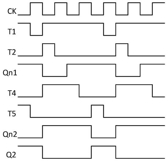
Figure 4.
Waveforms of the proposed prescaler in divide-by-3 mode.
The prescaler can work by removing M15, which further reduces the critical path. Under this condition, the performance under the divide-by-3 model depends mainly on the speed of the node T5 discharge and is not obviously affected by other nodes. M9 presents a stronger driving capability than M10, and a lower driving capability than M16 in the design. Therefore, when both M9 and M10 turn on, node T5 remains high. When M16 is also turned on, the T5 node is reduced to a low level. Under this condition, the discharge speed of M10 and M16 determines the division speed. However, an always-on M16 in divide-by-3 mode wastes a lot of energy, which is verified by simulation. We added M15 back to save power consumption.
3. Simulation and Measurement Results
3.1. Simulation Results
We have analyzed and compared the proposed prescaler with the conventional ones using an identical 40 nm CMOS process for fair comparisons, including the low power design based on E-TSPC DFFs in Reference [12], NOR-based and MUX-based prescaler. In addition, 2 fF capacitors are added to all of the nodes to emulate the parasitic capacitance from the layout. The simulation has been conducted in a typical process corner at 300 K temperature and a 1.1 V power supply. The speed under the divide-by-3 mode is chosen to represent the speed limit of the prescalers because the maximum operating frequencies under the divide-by-3 mode are always lower.
Figure 5 shows the proposed prescaler can operate at 7.2 GHz, and the prescaler can operate in divide-by-4 and divide-by-3 mode correctly when MC is “0” and “1”, respectively.
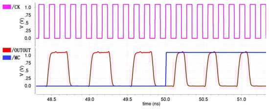
Figure 5.
Simulation results of the proposed prescaler operating at 7.2 GHz @ 1.1 V supply and room temperature.
Table 2 compares the maximum operating frequencies and the power consumption at the frequencies of different dividers. We define FoM of a frequency divider as
where Frequency is the maximum operating frequency of the prescaler and power is the power consumption at the maximum operating frequency respectively.
Table 2.
Performance of different structure of frequency dividers
The maximum operating frequency of the proposed prescaler is 7.2 GHz, which is 10.1%, 41.2% and 60.6% higher than those in Reference [12], NOR-based and MUX-based ones, respectively. The FoM is also 17.4%, 34.8% and 75.5% better, respectively.
3.2. Measurement Results
The proposed divider-by-3/4 prescaler has been designed and fabricated using SMIC 1P7M 40 nm CMOS technology. The chip microphotograph is shown in Figure 6 and the overall chip size is 512 × 650 μm2. The test chip contains pads, input buffer and output buffer to facilitate characterization. The size of the divider core circuit is 3.4 × 5.66 μm2 chip area.
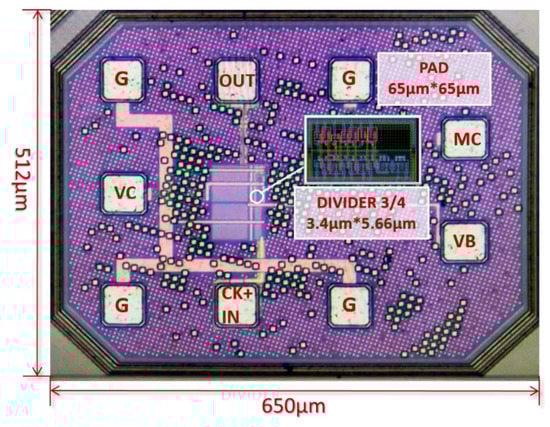
Figure 6.
Die photo of the divider test chip.
Figure 7 illustrates the setup for the frequency divider. The DC power of the buffers and the core is separated to test the power consumption of the divider accurately. The output is provided by an open drain NMOS on the chip and a bias tee externally. The buffering power and MC signal were provided by KEYSIGHT N6705B DC Power Analyzer and the core power was provided by KEYSIGHT B2902A precision source/measurement unit. The input signal was provided by a ROHDE and SCHWARZ SMB 100A signal generator, while the output signal was captured by a KEYSIGHT DSAV204A digital signal analyzer.
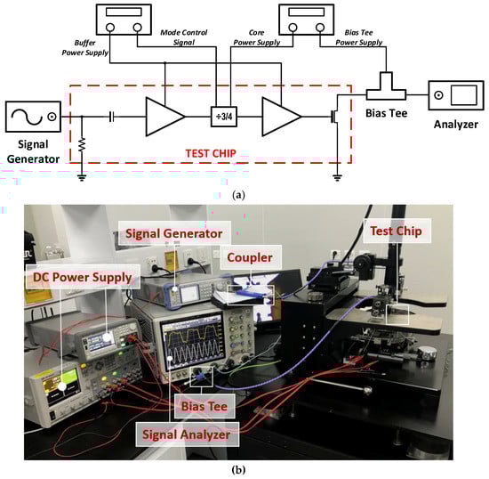
Figure 7.
The test setup. (a) The block diagram of the test setup; (b) photo of the test setup.
The maximum measured operating frequency is 9 GHz, whose power consumption is 0.304 mW under a 1.35 V supply with a 29.6 GHz/mW FoM in divide-by-3 mode. With a 1.1 V supply, the measured maximum operating frequency is 6.9 GHz, 4% lower than simulation due to underestimation of parasitics.
Figure 8 shows the measured output signals of the test chip operating at 6.9 GHz under 1.1 V, and 9 GHz under 1.35 V, respectively. The measured Vp-p of the output signals is lower than the internal supply voltage due to the open-drain buffer with a separate supply voltage. Measurement suggests that the divider can support a 9 GHz operation at both divide-by-3 and divide-by-4 modes.
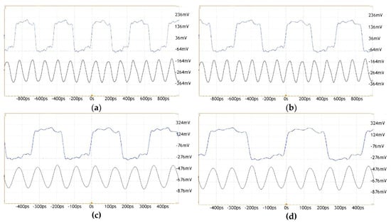
Figure 8.
The measured waveforms of (a) divide-by-3 at 6.9 GHz under 1.1 V; (b) divide-by-4 at 6.9 GHz under 1.1 V; (c) divide-by-3 at 9 GHz under 1.35V; (d) divide-by-4 at 9 GHz under 1.35 V.
Table 3 summarizes the measurement results of this work and compared with previous work based on TSPC and E-TSPC DFFs, including maximum operating frequency, power consumption and FoM. The table shows that the best FoM appears when the supply voltage is 1.1 V, and the highest maximum frequency works under 1.35V voltage. The proposed prescaler demonstrates the fastest speed and the best FoM.
Table 3.
Measurement performance.
4. Conclusions
In this paper, we present a high-speed, low-power divide-by-3/4 prescaler design based on E-TSPC DFFs. We add only two NMOS transistors to a divide-by-4 frequency divider to realize a programmable division ratio of 3 and 4. We have optimized the divider and cut down the total transistor count to 16. Consequently, power consumption was reduced. In addition, the performance was improved by minimizing the critical path. The simulation results show that the FoM of the proposed prescaler was 17.4%, 34.8% and 75.5% better than those in Reference [12], NOR-based and MUX-based ones, respectively. The proposed prescaler has been implemented in a 40 nm CMOS process, whose core only occupied a 3.4 × 5.66 μm2 chip area. The divider achieved the highest operating frequency of 9 GHz with 0.303 mW power consumption under a 1.35 V supply. The best measured FoM of the proposed prescaler was 31.7 GHz/mW under a 1.1 V supply.
Author Contributions
T.S. and J.L. proposed the idea and method; T.S. performed the simulations and experiments; C.S. analyzed the data; Z.X. reviewed the manuscript and provided valuable suggestions.
Funding
This research was supported by the National Natural Science Foundation of China under Grant NSFC 61674128.
Conflicts of Interest
The authors declare no conflict of interest.
References
- Song, Z.; Liu, X.; Zhao, X.; Liu, Q.; Jin, Z.; Chi, B. A low-power NB-IoT transceiver with digital-polar transmitter in 180-nm CMOS. IEEE Trans. Circuits Syst. I Pap. 2017, 64, 2569–2581. [Google Scholar] [CrossRef]
- Ratasuk, R.; Vejlgaard, B.; Mangalvedhe, N.; Ghosh, A. NB-IoT system for M2M communication. In Proceedings of the 2016 IEEE wireless communications and networking conference, Doha, Qatar, 3–6 April 2016; pp. 1–5. [Google Scholar]
- Anand, S.; Routray, S.K. Issues and challenges in healthcare narrowband IoT. In Proceedings of the 2017 International Conference on Inventive Communication and Computational Technologies (ICICCT), Coimbatore, India, 10–11 March 2017; pp. 486–489. [Google Scholar]
- Wang, X.; Büsze, B.; Vandecasteele, M.; Liu, Y.H.; Bachmann, C.; Philips, K. The design challenges of IoT: From system technologies to ultra-low power circuits. IEICE Trans. Electron. 2017, 100, 515–522. [Google Scholar] [CrossRef]
- Imani, A.; Hashemi, H. Distributed injection-locked frequency dividers. IEEE J. Solid-State Circuits 2017, 52, 2083–2093. [Google Scholar] [CrossRef]
- Jang, S.L.; Kung, T.C.; Hsue, C.W. Wide-locking range divide-by-4 injection-locked frequency divider using linear mixer approach. IEEE Microwave Wireless Compon. Lett. 2017, 27, 398–400. [Google Scholar] [CrossRef]
- Chen, Y.T.; Li, M.W.; Kuo, H.C.; Huang, T.H.; Chuang, H.R. Low-voltage K-band divide-by-3 injection-locked frequency divider with floating-source differential injector. IEEE Trans. Microwave Theory Tech. 2012, 60, 60–67. [Google Scholar] [CrossRef]
- Jiang, W.; Yu, F. 4.2 GHz 0.81 mW triple-modulus prescaler based on true single-phase clock. Electron. Lett. 2016, 52, 1007–1008. [Google Scholar] [CrossRef]
- Liu, H.; Zhang, X.; Dai, Y.; Lv, Y. Low power cmos high-speed dual-modulus 15/16 prescaler for wireless communications. In Proceedings of the 2011 Third International Conference on Communications and Mobile Computing, Washington, DC, USA, 18–20 April 2011; pp. 397–400. [Google Scholar]
- Chen, W.H.; Jung, B. High-speed low-power true single-phase clock dual-modulus prescalers. IEEE Trans. Circuits Syst. Express Briefs 2011, 58, 144–148. [Google Scholar] [CrossRef]
- Manthena, V.K.; Do, M.A.; Boon, C.C.; Yeo, K.S. A low-power single-phase clock multiband flexible divider. IEEE Trans. Very Large Scale Integr. VLSI Syst. 2012, 20, 376–380. [Google Scholar] [CrossRef]
- Jiang, W.; Yu, F. A novel high-speed divide-by-3/4 prescalar. In Proceedings of the 2016 IEEE Advanced Information Management, Communicates, Electronic and Automation Control Conference (IMCEC), Xi’an, China, 3–5 October 2016; pp. 479–482. [Google Scholar]
- Macaitis, V.; Navickas, R. Design of High Frequency, Low Phase Noise LC Digitally Controlled Oscillator for 5G Intelligent Transport Systems. Electronics 2019, 8, 72. [Google Scholar] [CrossRef]
- Gu, Q.J.; Jian, H.Y.; Xu, Z.; Wu, Y.C.; Chang, M.C.F.; Baeyens, Y.; Chen, Y.K. CMOS prescaler (s) with maximum 208-GHz dividing speed and 37-GHz time-interleaved dual-injection locking range. IEEE Trans. Circuits Syst. Express Briefs 2011, 58, 393–397. [Google Scholar] [CrossRef]
- Zhu, W.; Yang, H.; Gao, T.; Liu, F.; Yin, T.; Zhang, D.; Zhang, H. A 5.8-GHz wideband TSPC divide-by-16/17 dual modulus prescaler. IEEE Trans. Very Large Scale Integr. VLSI Syst. 2015, 23, 194–197. [Google Scholar]
- Krishna, M.V.; Do, M.A.; Yeo, K.S.; Boon, C.C.; Lim, W.M. Design and analysis of ultra low power true single phase clock CMOS 2/3 prescaler. IEEE Trans. Circuits Syst. Regul. Pap. 2010, 57, 72–82. [Google Scholar] [CrossRef]
© 2019 by the authors. Licensee MDPI, Basel, Switzerland. This article is an open access article distributed under the terms and conditions of the Creative Commons Attribution (CC BY) license (http://creativecommons.org/licenses/by/4.0/).