A Parasitic Resonator-Based Diamond-Shaped Microstrip Antenna for Microwave Imaging Applications

 ,
,  ,
,  ,
, 
Abstract
:1. Introduction
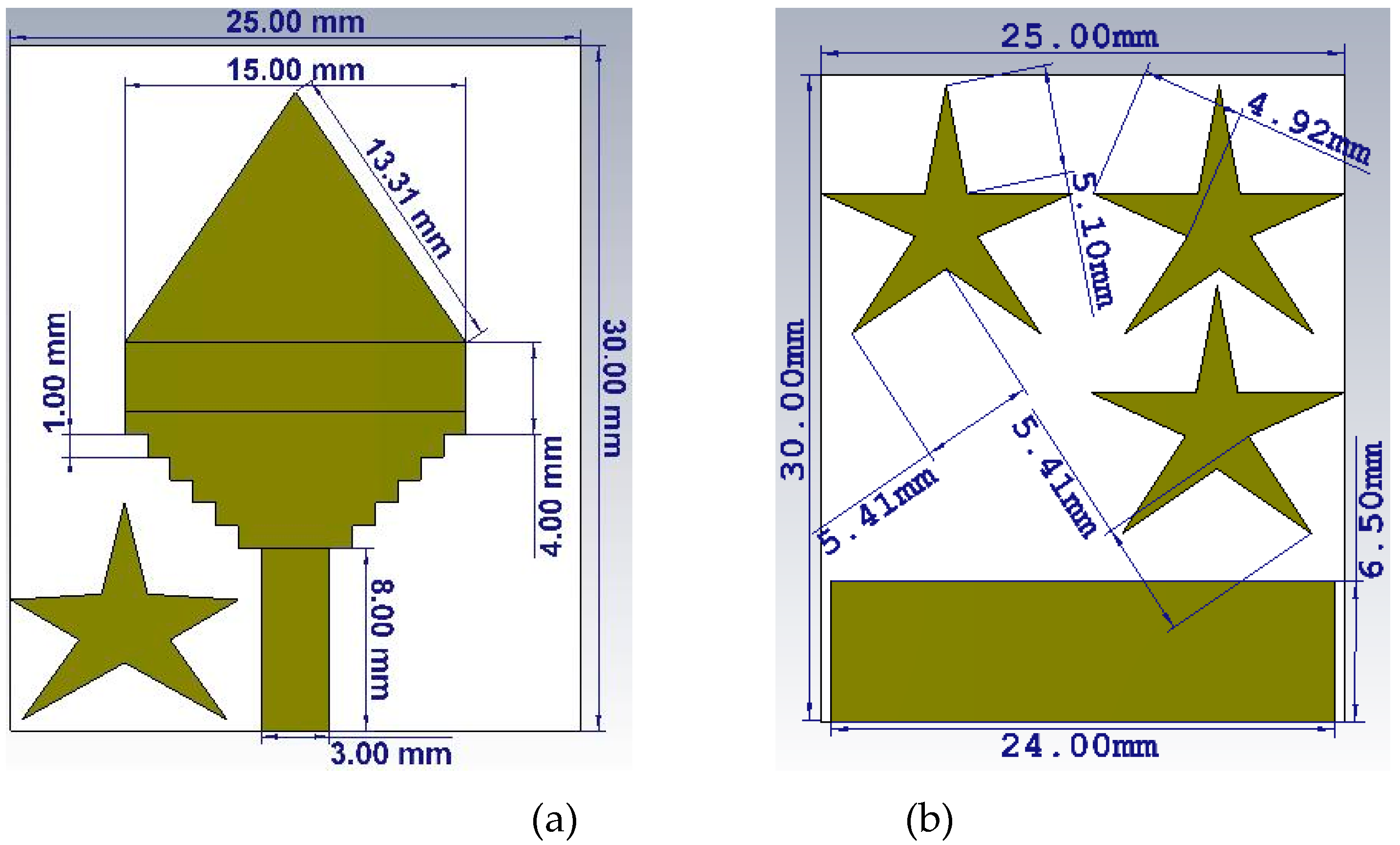
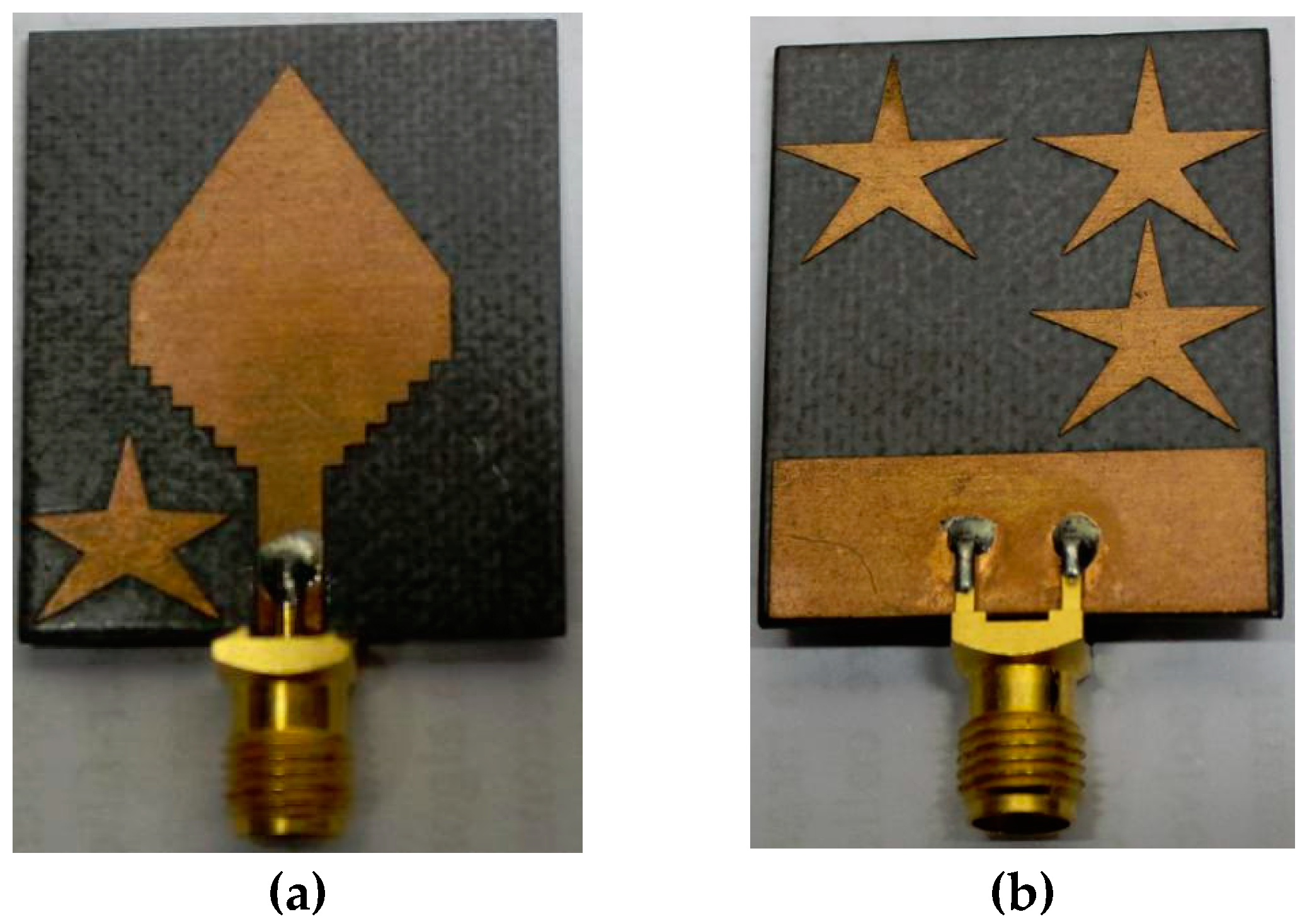
2. Antenna Design
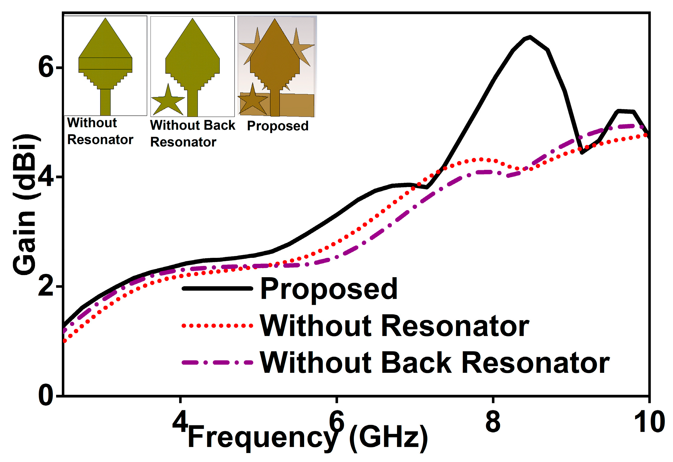
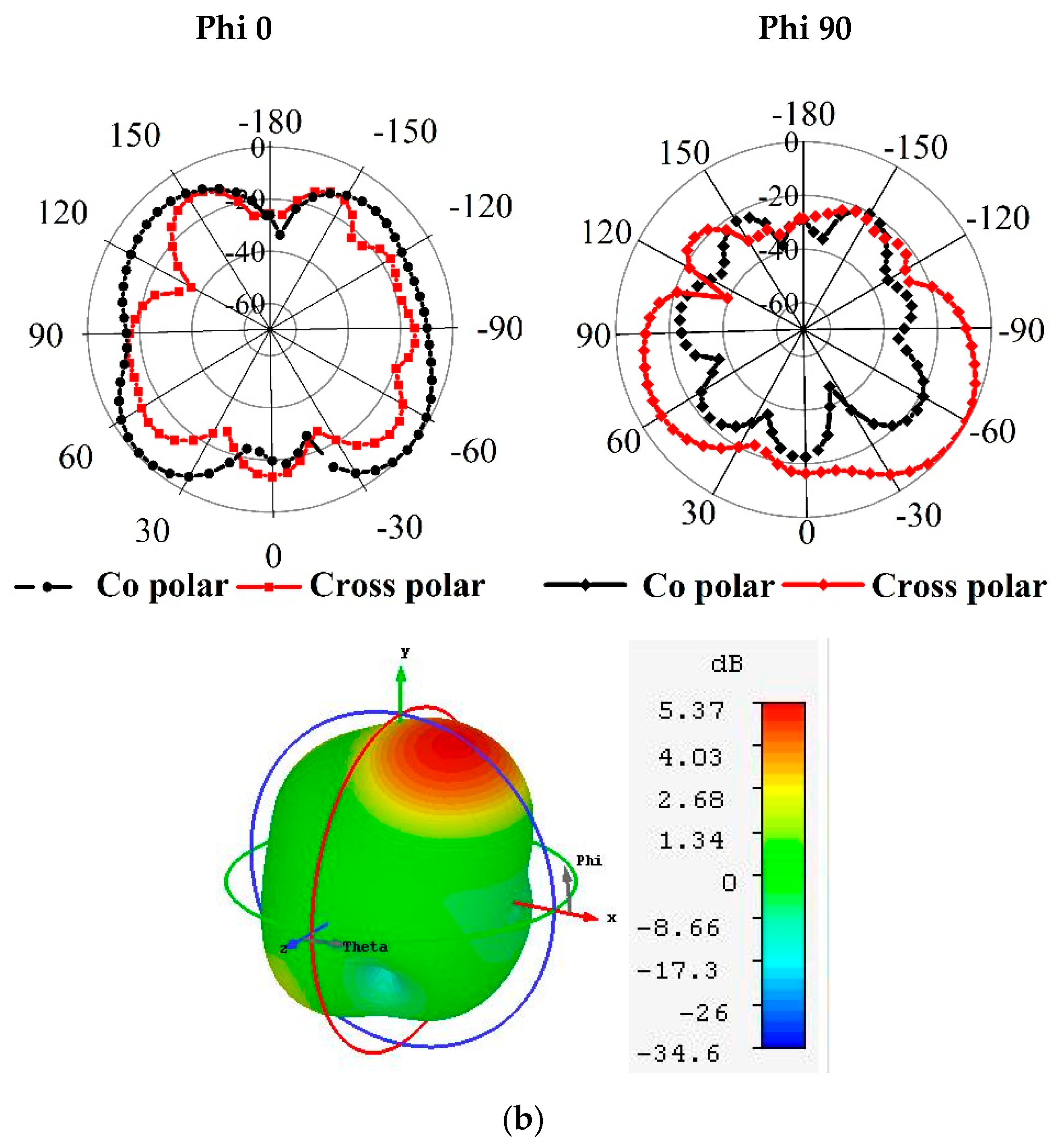
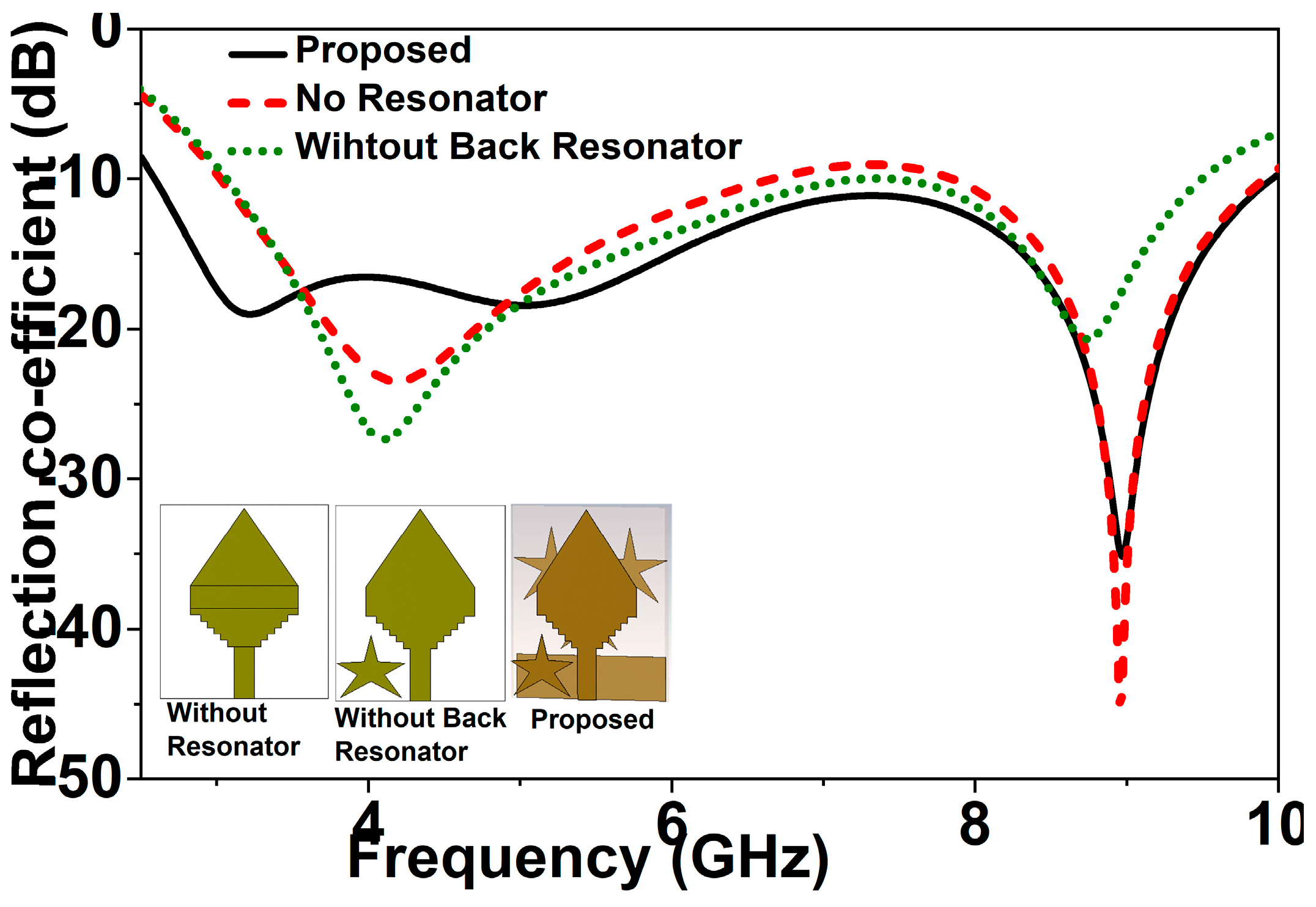
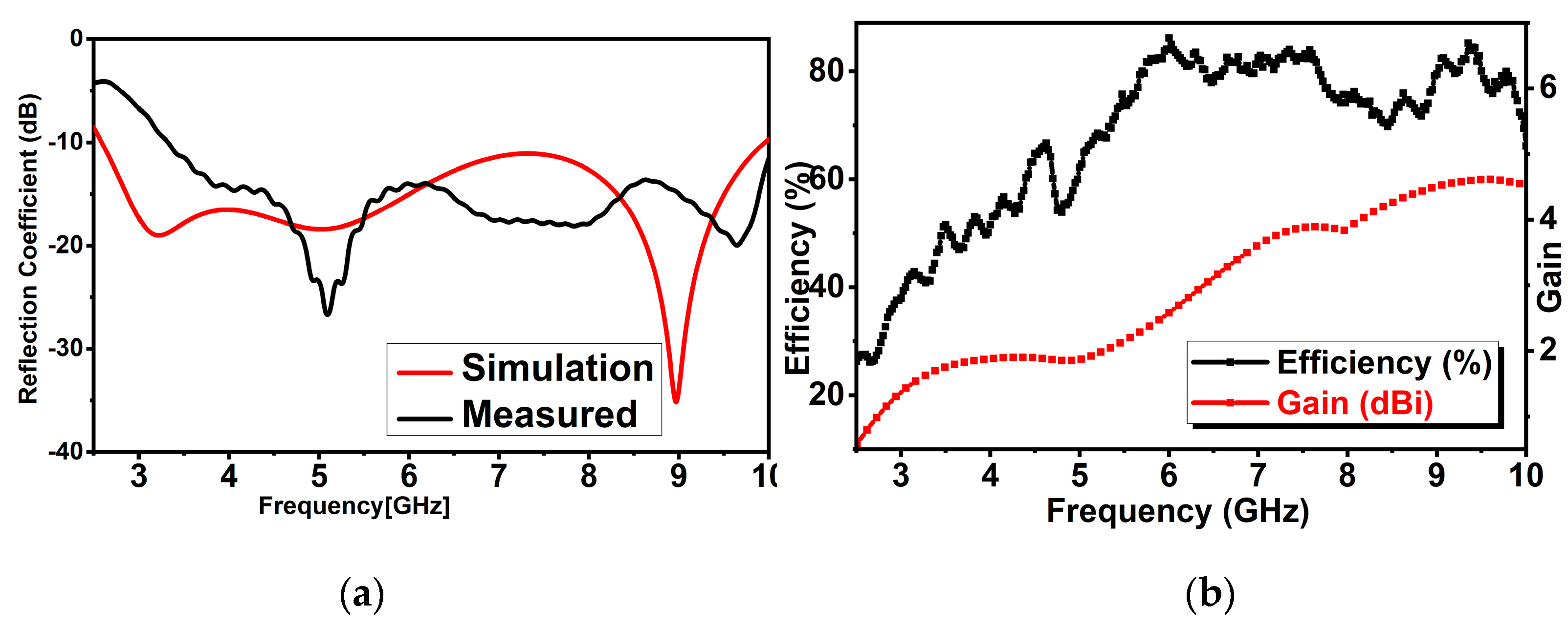
3. Results and Discussion
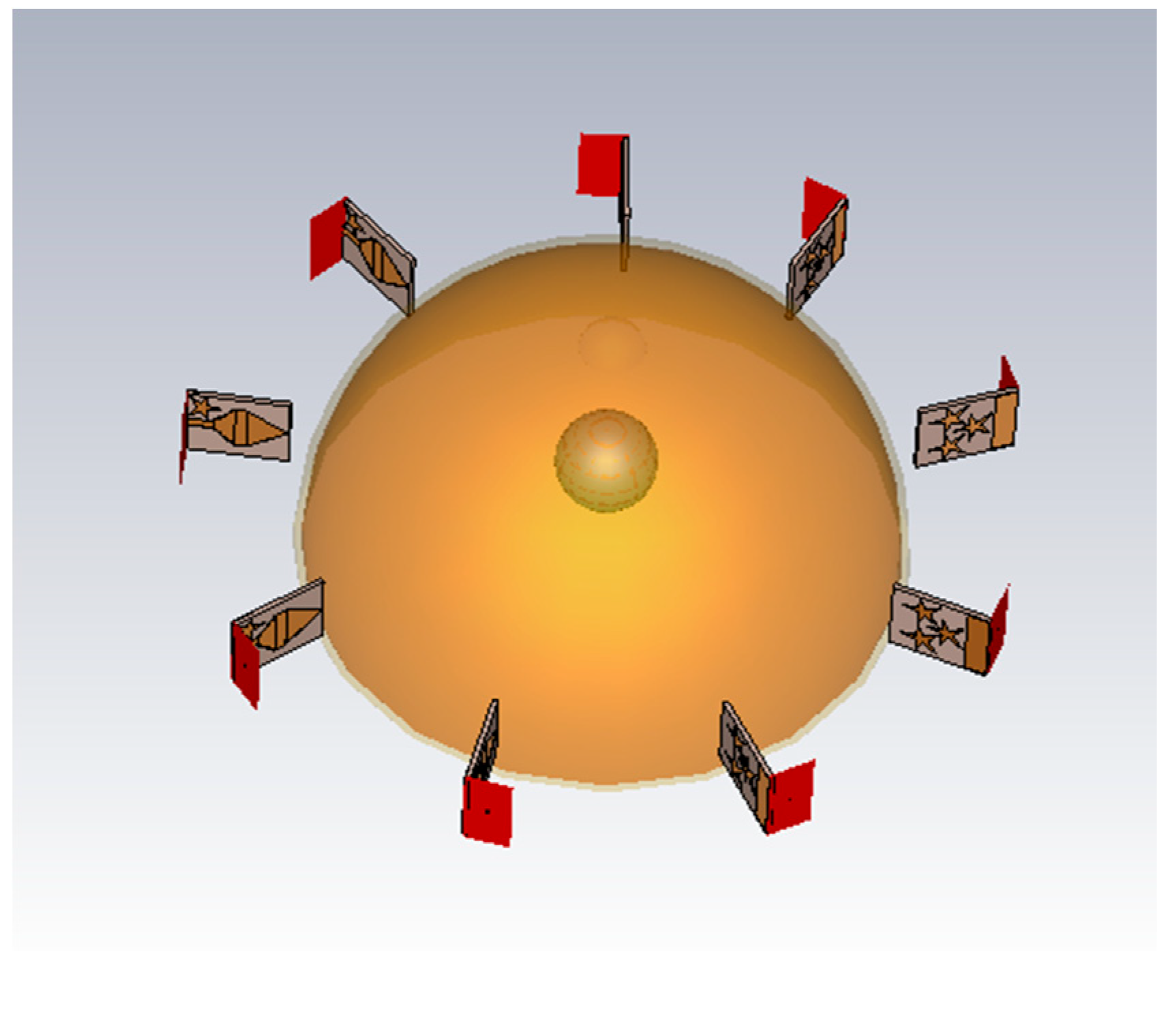
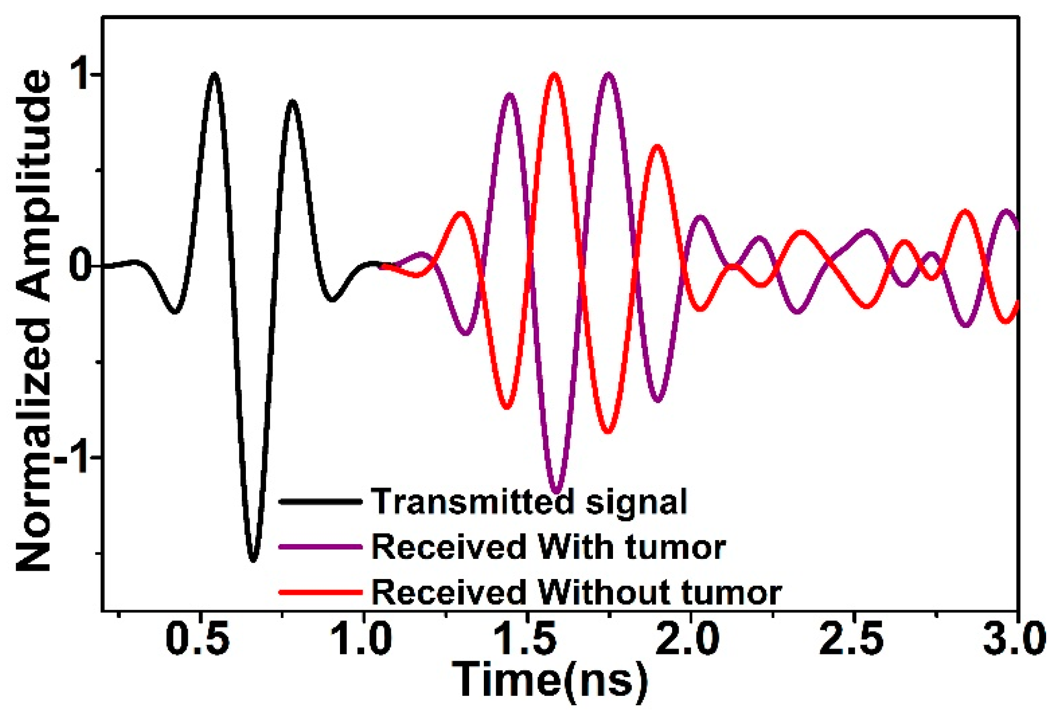
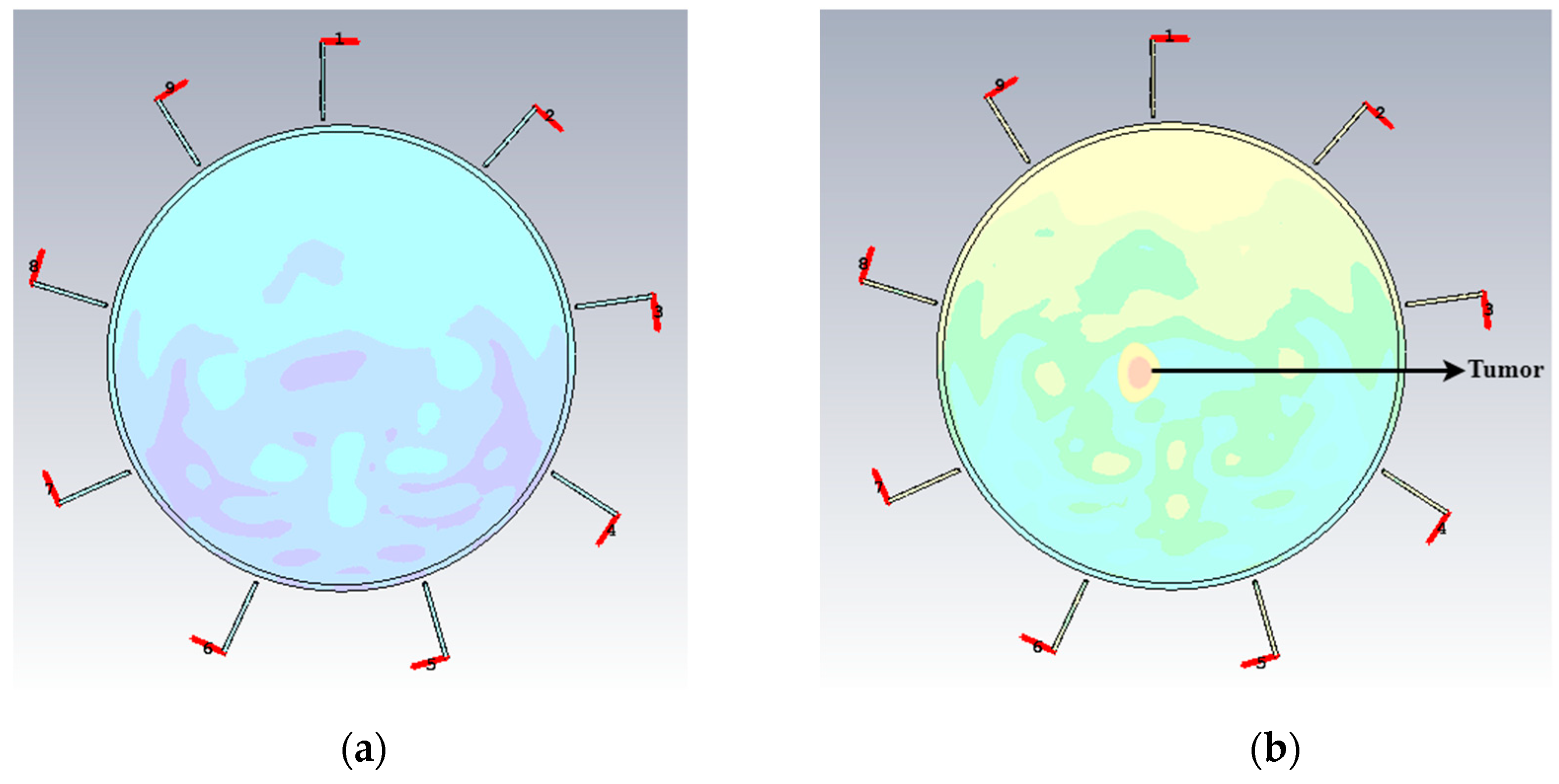
4. Imaging Performances
5. Conclusions
Author Contributions
Funding
Conflicts of Interest
References
- Pan, J. Medical Applications of Ultra-Wideband (UWB). Survey Paper. 2007. Available online: https://www.cse.wustl.edu/~jain/cse574-08/ftp/uwb/ (accessed on 10 February 2019).
- Ojaroudi, M.; Ghobadi, C.; Nourinia, J. Small square monopole antenna with inverted T-shaped notch in the ground plane for UWB application. IEEE Antennas Wirel. Propag. Lett. 2009, 8, 728–731. [Google Scholar] [CrossRef]
- Wong, H.; So, K.K.; Gao, X. Bandwidth enhancement of a monopolar patch antenna with V-shaped slot for car-to-car and WLAN communications. IEEE Trans. Veh. Technol. 2016, 65, 1130–1136. [Google Scholar] [CrossRef]
- Pandey, G.; Singh, H.; Bharti, P.; Meshram, M. Metamaterial-based UWB antenna. Electron. Lett. 2014, 50, 1266–1268. [Google Scholar] [CrossRef]
- Liu, H.-W.; Yang, C.-F. Miniature hook-shaped monopole antenna for UWB applications. Electron. Lett. 2010, 46, 265–266. [Google Scholar] [CrossRef]
- Samsuzzaman, M.; Islam, M.T. A semicircular shaped super wideband patch antenna with high bandwidth dimension ratio. Microw. Opt. Technol. Lett. 2015, 57, 445–452. [Google Scholar] [CrossRef]
- Abbosh, A. Miniaturization of planar ultrawideband antenna via corrugation. IEEE Antennas Wirel. Propag. Lett. 2008, 7, 685–688. [Google Scholar] [CrossRef]
- Gao, X.; Yang, H.W.; Lai, H.W.; So, K.K.; Won, H.; Xue, Q. CPW-fed slot antenna with dual band-notched characteristic for UWB application. In Proceedings of the 4th International High Speed Intelligent Communication Forum, Nanjing, China, 10–11 May 2012; pp. 1–3. [Google Scholar]
- Lakrit, S.; Ammor, H.; Terhzaz, J.; Tribak, A. Realization and Measurements of a Miniature Square Patch Antenna for Ultra Wideband Applications. Int. J. Microw. Opt. Technol. 2015, 10, 307–313. [Google Scholar]
- Liu, H.; Zhu, S.; Wen, P.; Xiao, X.; Che, W.; Guan, X. Flexible CPW-fed fishtail-shaped antenna for dual-band applications. IEEE Antennas Wirel. Propag. Lett. 2014, 13, 770–773. [Google Scholar]
- Azim, R.; Islam, T.M.; Misran, N. Compact tapered-shape slot antenna for UWB applications. IEEE Antennas Wirel. Propag. Lett. 2011, 10, 1190–1193. [Google Scholar] [CrossRef]
- Natarajan, R.; George, V.J.; Kanagasabai, M.; Shrivastav, K.A. A compact antipodal Vivaldi antenna for UWB applications. IEEE Antennas Wirel. Propag. Lett. 2015, 14, 1557–1560. [Google Scholar] [CrossRef]
- Mahmud, M.; Islam, T.M.; Samsuzzaman, M.; Kibria, S.; Misran, N. Design and parametric investigation of directional antenna for microwave imaging application. IET Microw. Antennas Propag. 2016, 11, 770–778. [Google Scholar] [CrossRef]
- Sharma, M.; Shrivastava, V. Printed fractal elliptical monopole antenna for UWB application. In Proceedings of the 2008 International Conference on Recent Advances in Microwave Theory and Applications, Jaipur, India, 21–24 November 2008; pp. 374–376. [Google Scholar]
- Shaalan, A.A.; Ramadan, M. Design of a Compact Hexagonal Monopole Antenna for Ultra—Wideband Applications. J. Infrared Millim. Terahertz Waves 2010, 31, 958–968. [Google Scholar] [CrossRef]
- Yang, B.Y.; Zhang, S.F.; Zhang, F.; Zhang, L.; Jiao, Y.C. A novel compact CPW-fed planar monopole antenna with modified stair-style ground for ultra-wideband applications. Microw. Opt. Technol. Lett. 2010, 52, 2100–2104. [Google Scholar] [CrossRef]
- Liu, L.; Cheung, S.; Azim, R.; Islam, M.T. A compact circular-ring antenna for ultra-wideband applications. Microw. Opt. Technol. Lett. 2011, 53, 2283–2288. [Google Scholar] [CrossRef]
- Isik, G.; Topaloglu, S. A Compact Size 4–19.1 GHz Heart Shape UWB Antenna with Triangular Patches. Int. J. Antennas Propag. 2013, 2013, 614754. [Google Scholar] [CrossRef]
- Fear, E.C.; Hagness, S.C.; Meaney, P.M.; Okoniewski, M.; Stuchly, M.A. Enhancing breast tumor detection with near-field imaging. IEEE Microw. Mag. 2002, 3, 48–56. [Google Scholar] [CrossRef]
- Jossinet, J.; Schmitt, M. A review of parameters for the bioelectrical characterization of breast tissue. Ann. N. Y. Acad. Sci. 1999, 873, 30–41. [Google Scholar] [CrossRef] [PubMed]
- Islam, M.T.; Mahmud, M.Z.; Misran, N.; Takada, J.-I.; Cho, M. Microwave Breast Phantom Measurement System With Compact Side Slotted Directional Antenna. IEEE Access 2017, 5, 5321–5330. [Google Scholar] [CrossRef]
- Belrose, J.S. The Sounds of a Spark Transmitter: Telegraphy and Telephony. Adventures CyberSound. 1994. Available online: http://www.hammondmuseumofradio.org/spark.html (accessed on 10 February 2019).
- Torres, C.F.; Monroy, J.M.; Morales, H.L.; Pérez, R.C.; Tellez, A.C. Heart shaped monopole antenna with defected ground plane for UWB applications. In Proceedings of the 11th International Conference on Electrical Engineering, Computing Science and Automatic Control (CCE), Campeche, Mexico, 29 September–3 October 2014; pp. 1–4. [Google Scholar]
- Mahmud, M.; Kibria, S.; Samsuzzaman, M.; Misran, N.; Islam, M.T. A New High Performance Hibiscus Petal Pattern Monopole Antenna for UWB Applications. Appl. Comput. Electromagn. Soc. J. 2016, 31, 373–380. [Google Scholar]
- Gautam, A.K.; Yadav, S.; Kanaujia, B.K. A CPW-fed compact UWB microstrip antenna. IEEE Antennas Wirel. Propag. Lett. 2013, 12, 151–154. [Google Scholar] [CrossRef]
- Amineh, R.K.; Trehan, A.; Nikolova, N.K. TEM horn antenna for ultra-wide band microwave breast imaging. Prog. Electromagn. Res. 2009, 13, 59–74. [Google Scholar] [CrossRef]


| Properties | Antenna Performance |
|---|---|
| Dimension | 30 × 25 × 1.6 mm3 |
| Substrate | Rogers RT5880 |
| Operating Bandwidth | 2.7 GHz to 10.3 GHz |
| Fractional Bandwidth | 116.92% |
| Gain | 6.2 dBi |
| Efficiency | 80% |
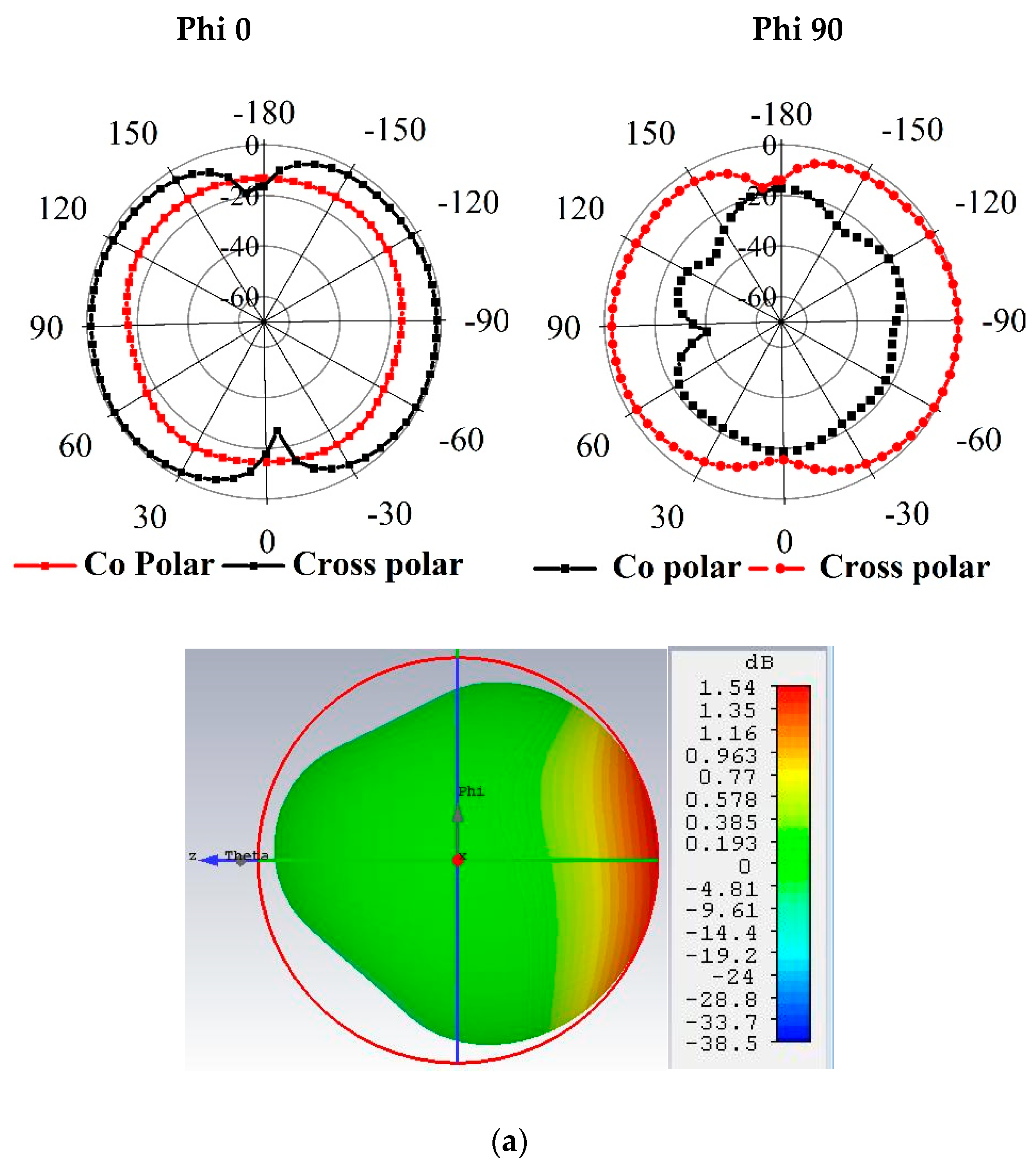
| Radiation Pattern | Unidirectional |
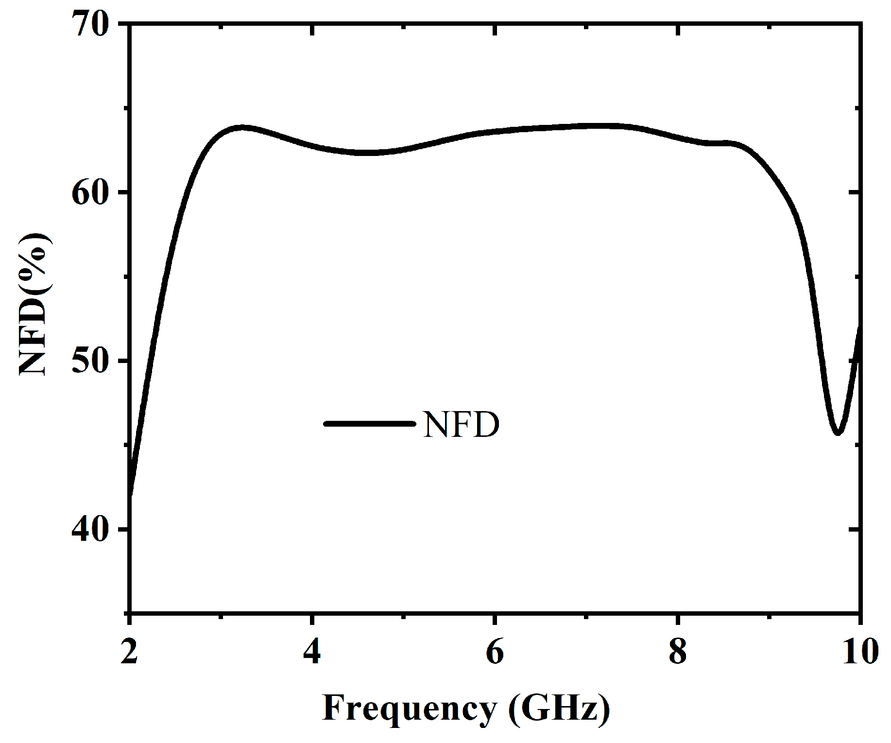
| Near Field Directivity (NFD) | 64% |
© 2019 by the authors. Licensee MDPI, Basel, Switzerland. This article is an open access article distributed under the terms and conditions of the Creative Commons Attribution (CC BY) license (http://creativecommons.org/licenses/by/4.0/).
Share and Cite
Mahmud, M.Z.; Islam, M.T.; Almutairi, A.F.; Samsuzzaman, M.; Acharjee, U.K.; Islam, M.T. A Parasitic Resonator-Based Diamond-Shaped Microstrip Antenna for Microwave Imaging Applications. Electronics 2019, 8, 434. https://doi.org/10.3390/electronics8040434
Mahmud MZ, Islam MT, Almutairi AF, Samsuzzaman M, Acharjee UK, Islam MT. A Parasitic Resonator-Based Diamond-Shaped Microstrip Antenna for Microwave Imaging Applications. Electronics. 2019; 8(4):434. https://doi.org/10.3390/electronics8040434
Chicago/Turabian StyleMahmud, Md Zulfiker, Md Tarikul. Islam, Ali F. Almutairi, Md Samsuzzaman, U.K. Acharjee, and Mohammad Tariqul Islam. 2019. "A Parasitic Resonator-Based Diamond-Shaped Microstrip Antenna for Microwave Imaging Applications" Electronics 8, no. 4: 434. https://doi.org/10.3390/electronics8040434
APA StyleMahmud, M. Z., Islam, M. T., Almutairi, A. F., Samsuzzaman, M., Acharjee, U. K., & Islam, M. T. (2019). A Parasitic Resonator-Based Diamond-Shaped Microstrip Antenna for Microwave Imaging Applications. Electronics, 8(4), 434. https://doi.org/10.3390/electronics8040434