Open Source Data Logging and Data Visualization for an Isolated PV System


Abstract
:1. Introduction
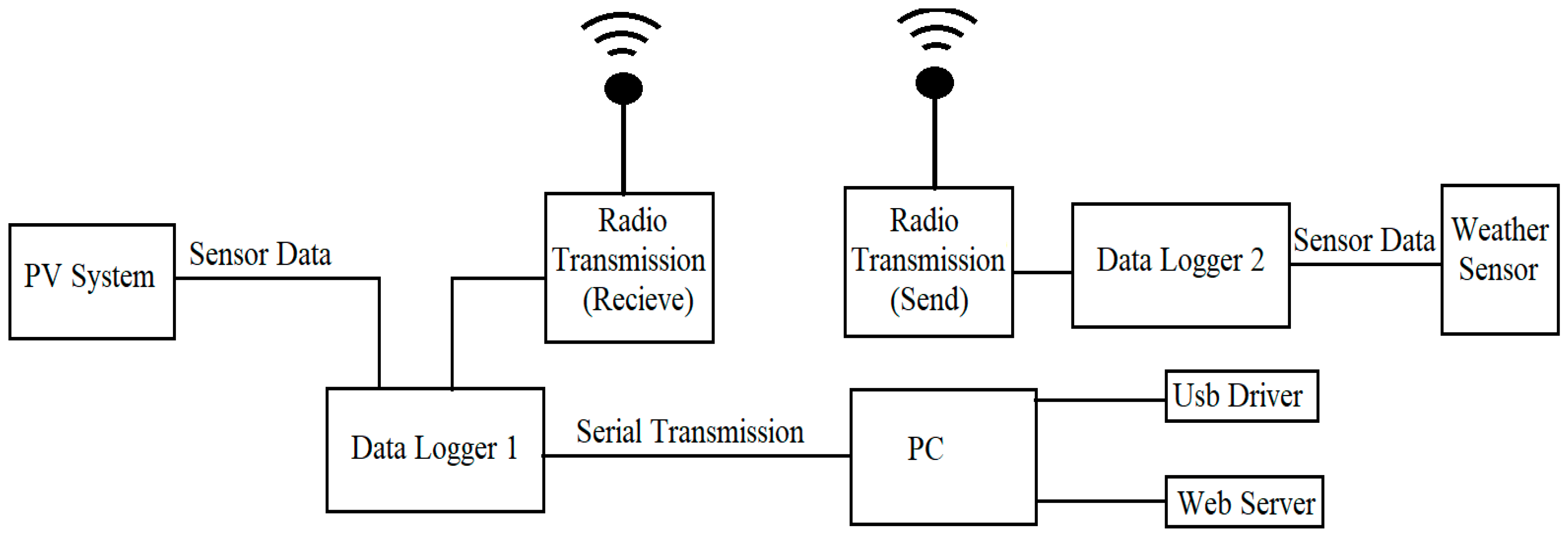
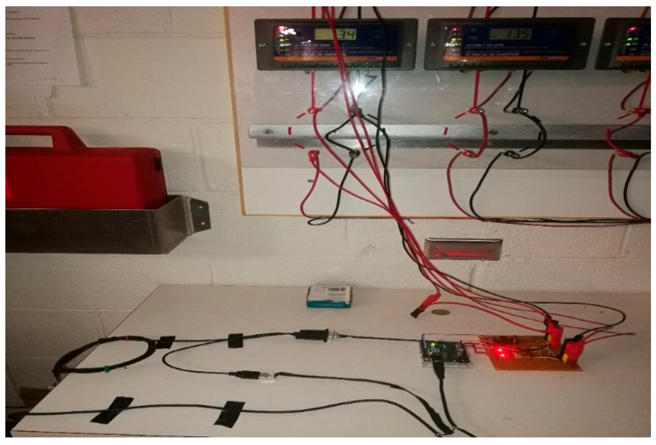
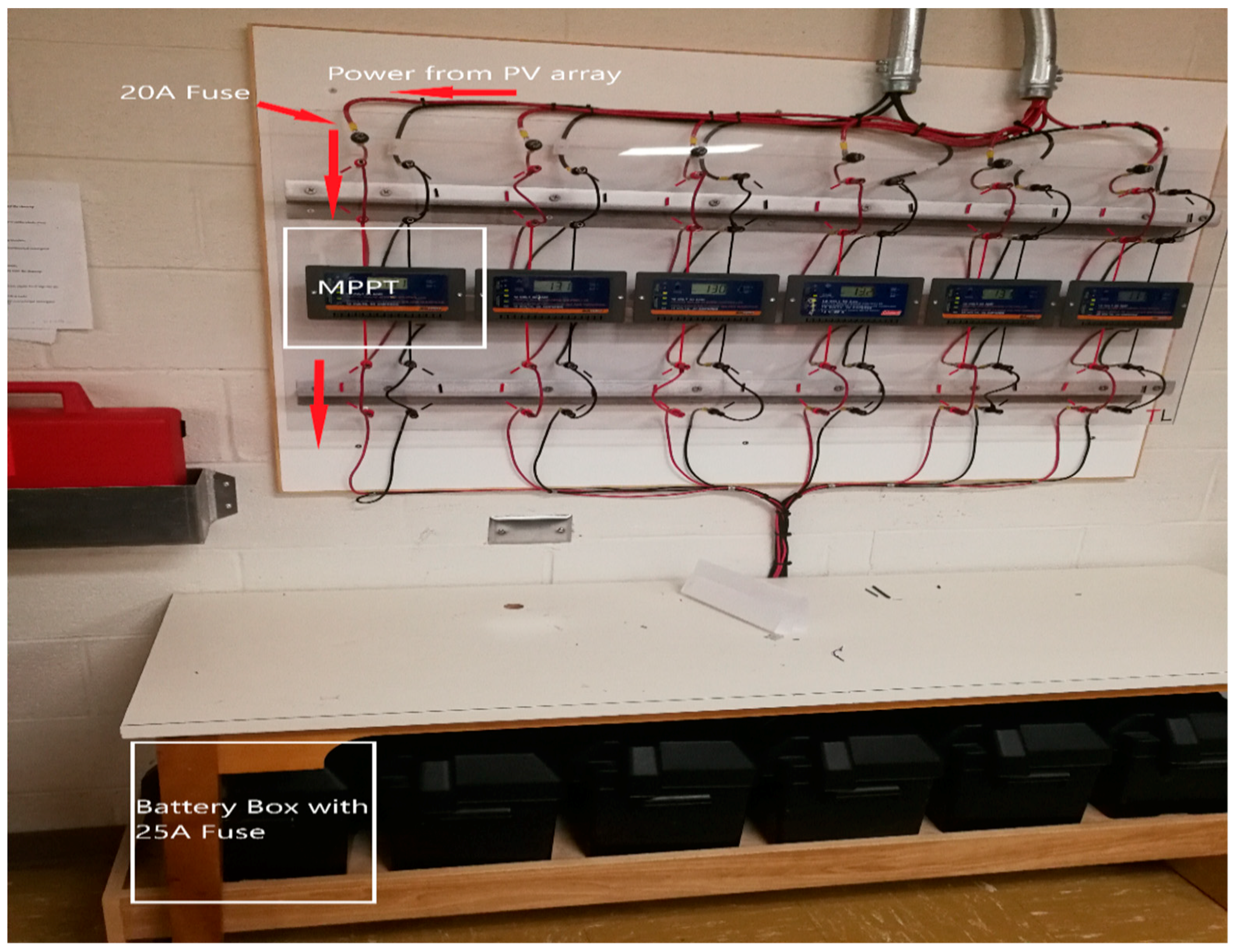
2. Overall System Setup
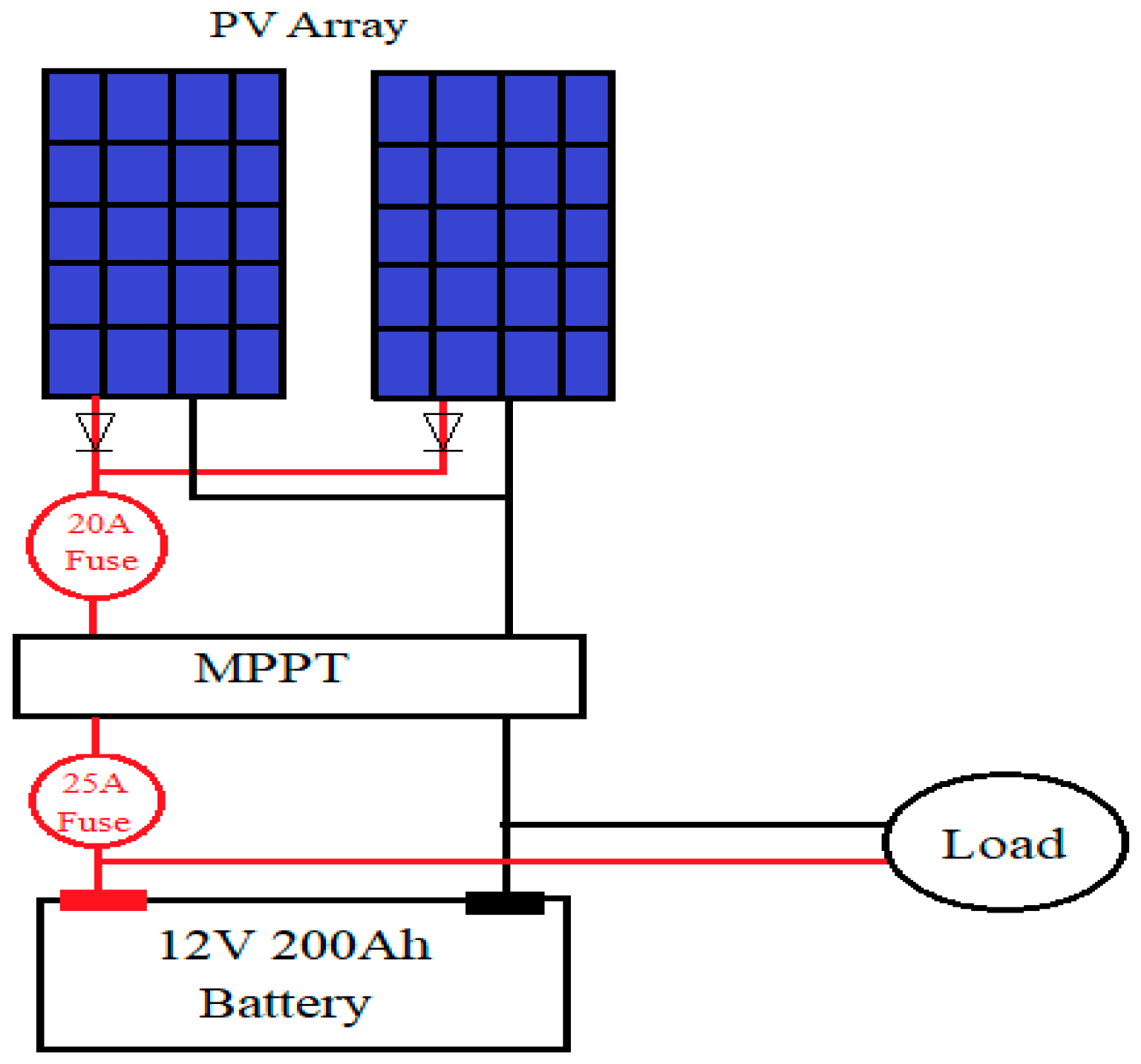
3. PV System
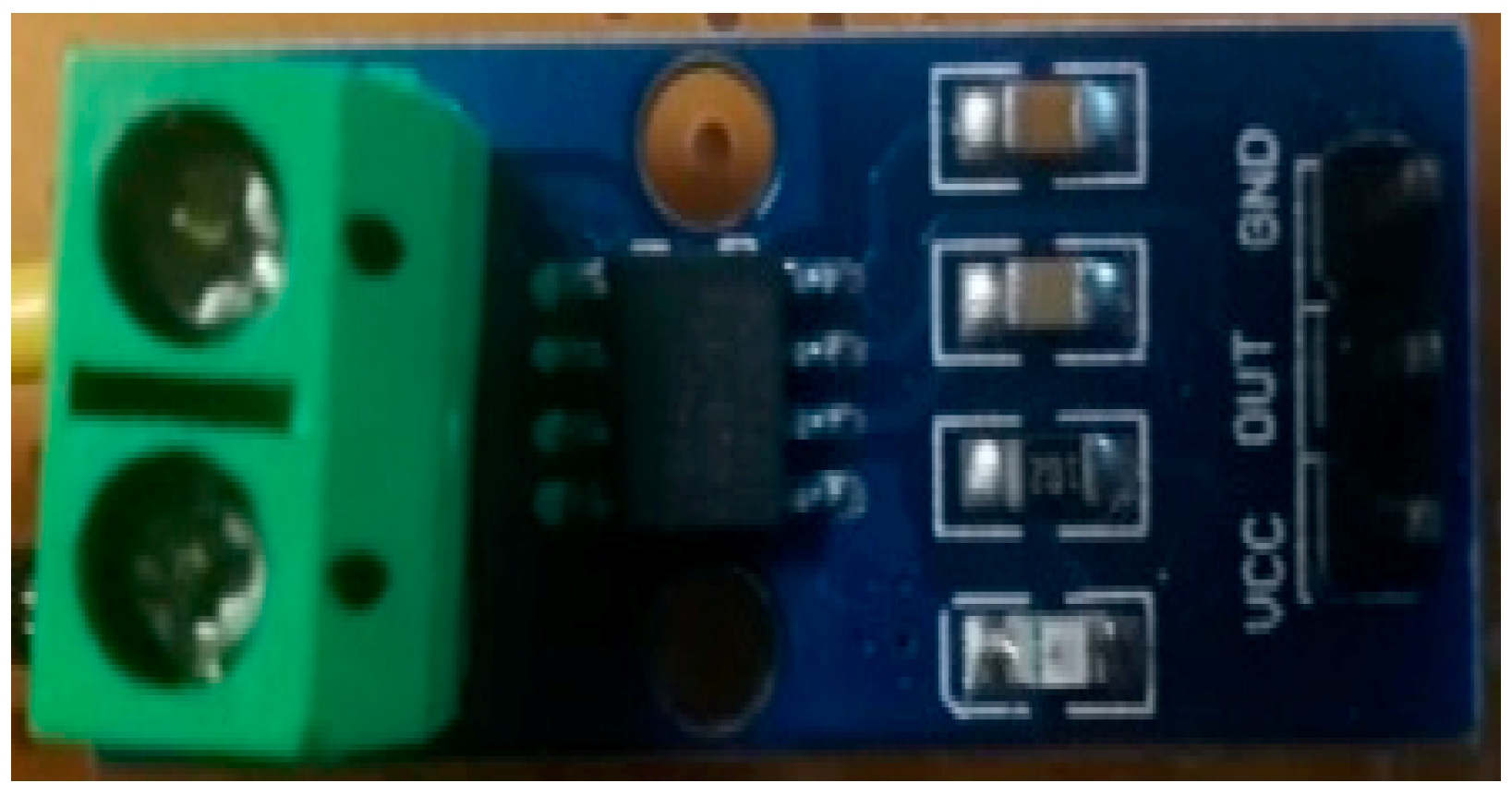
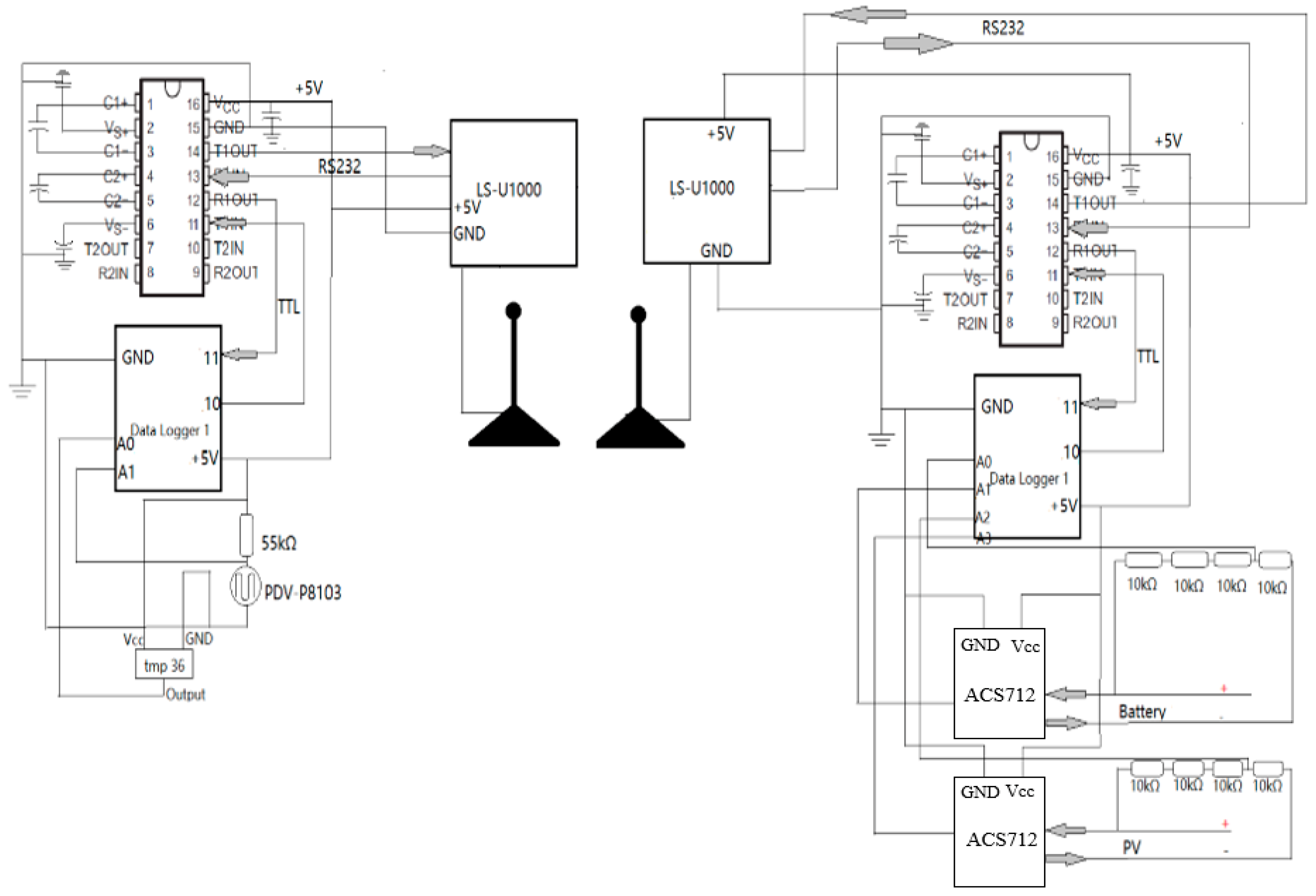
4. Sensors
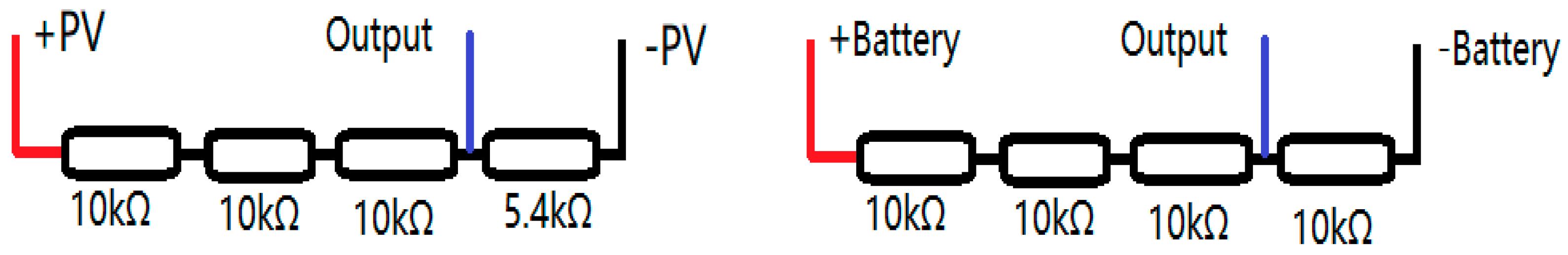
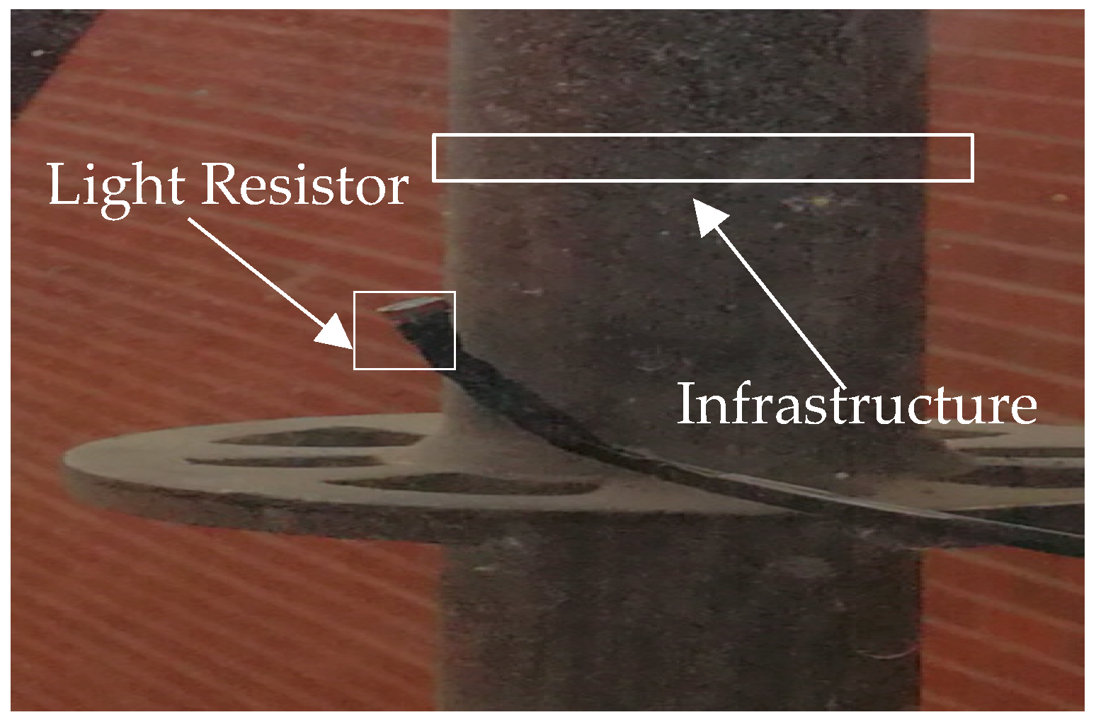
4.1. Sensors in PV System
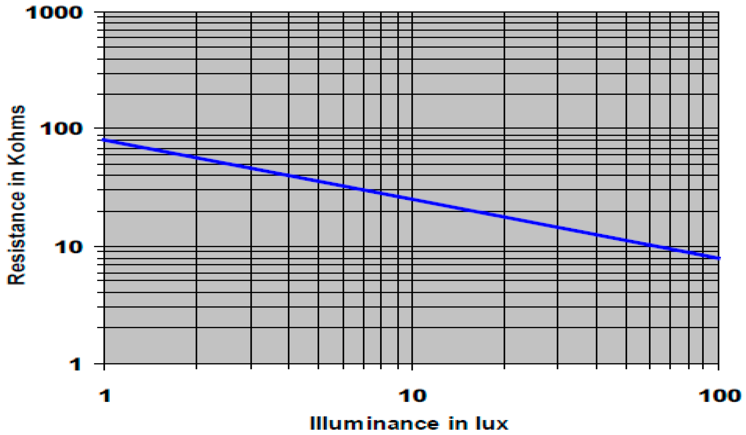
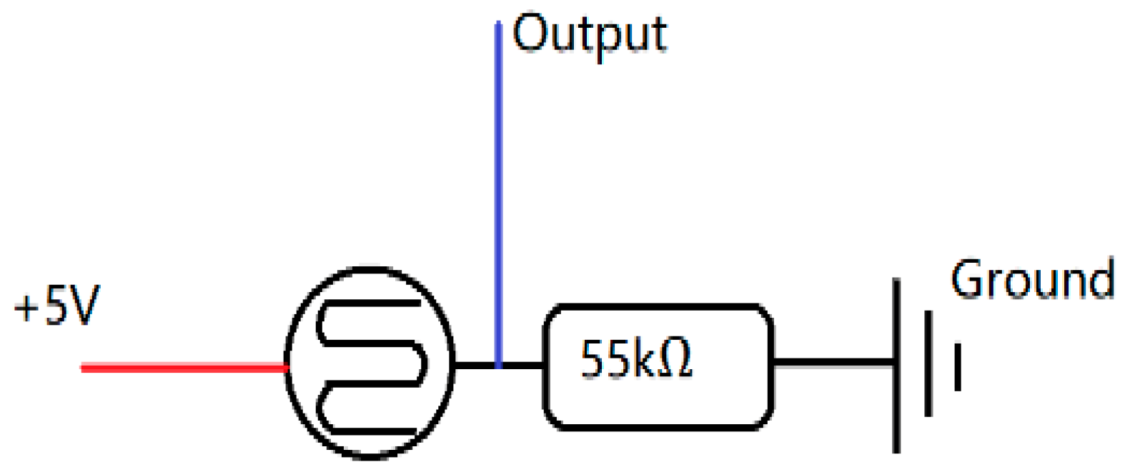
4.2. Sensors for Weather Data
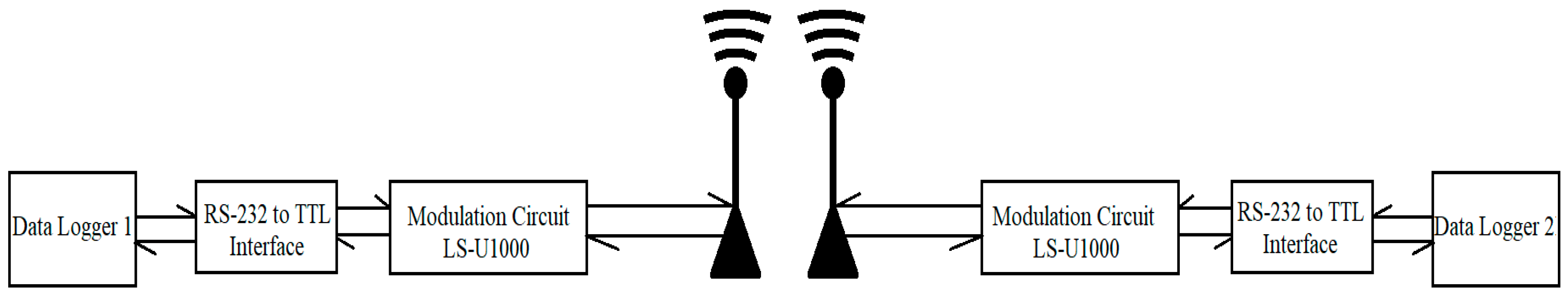
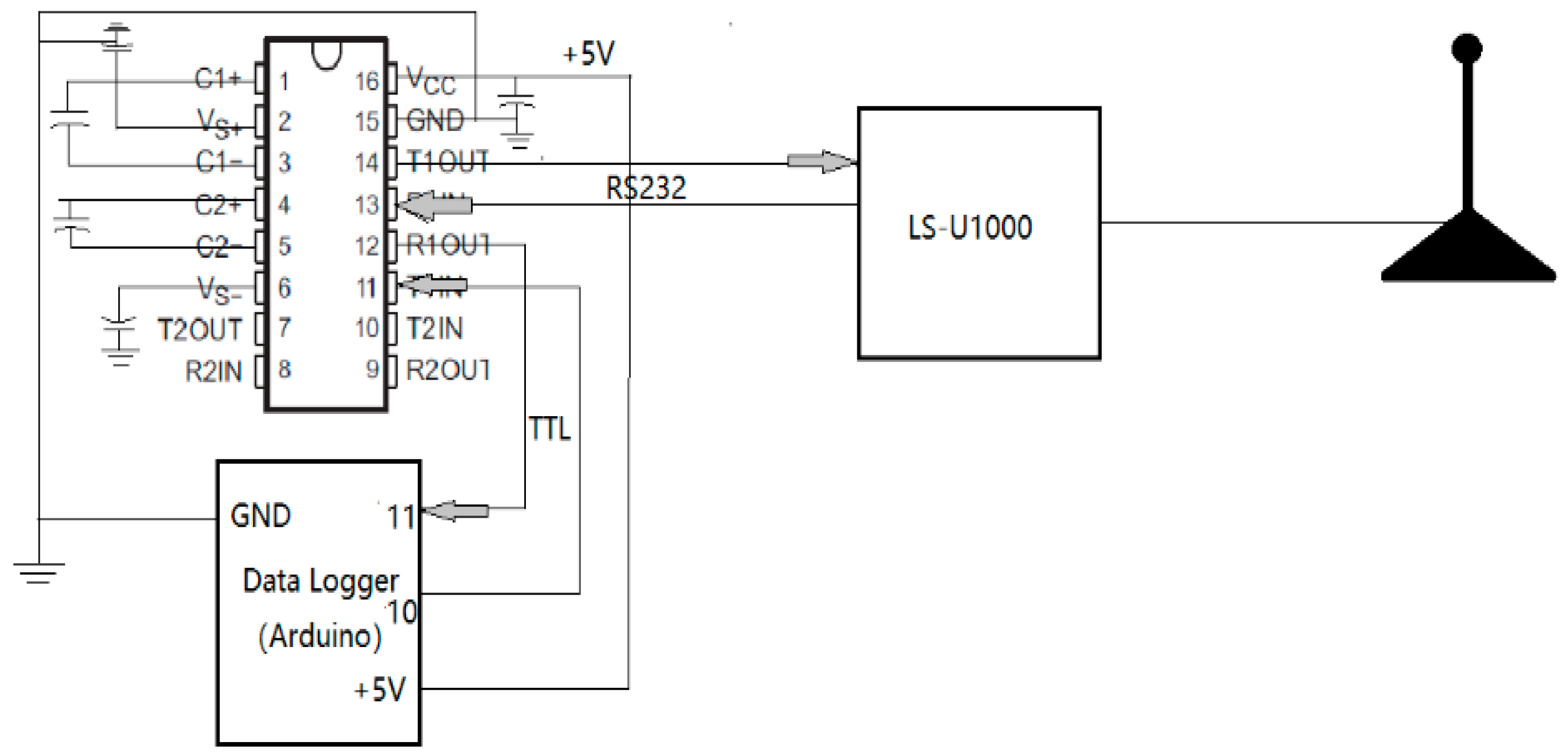
5. Radio Communication System
RS232-TTL Interface
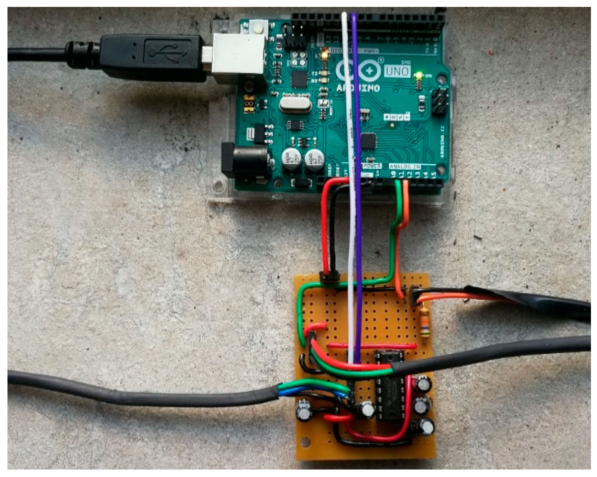
6. Programs in Arduino Boards and Python Script
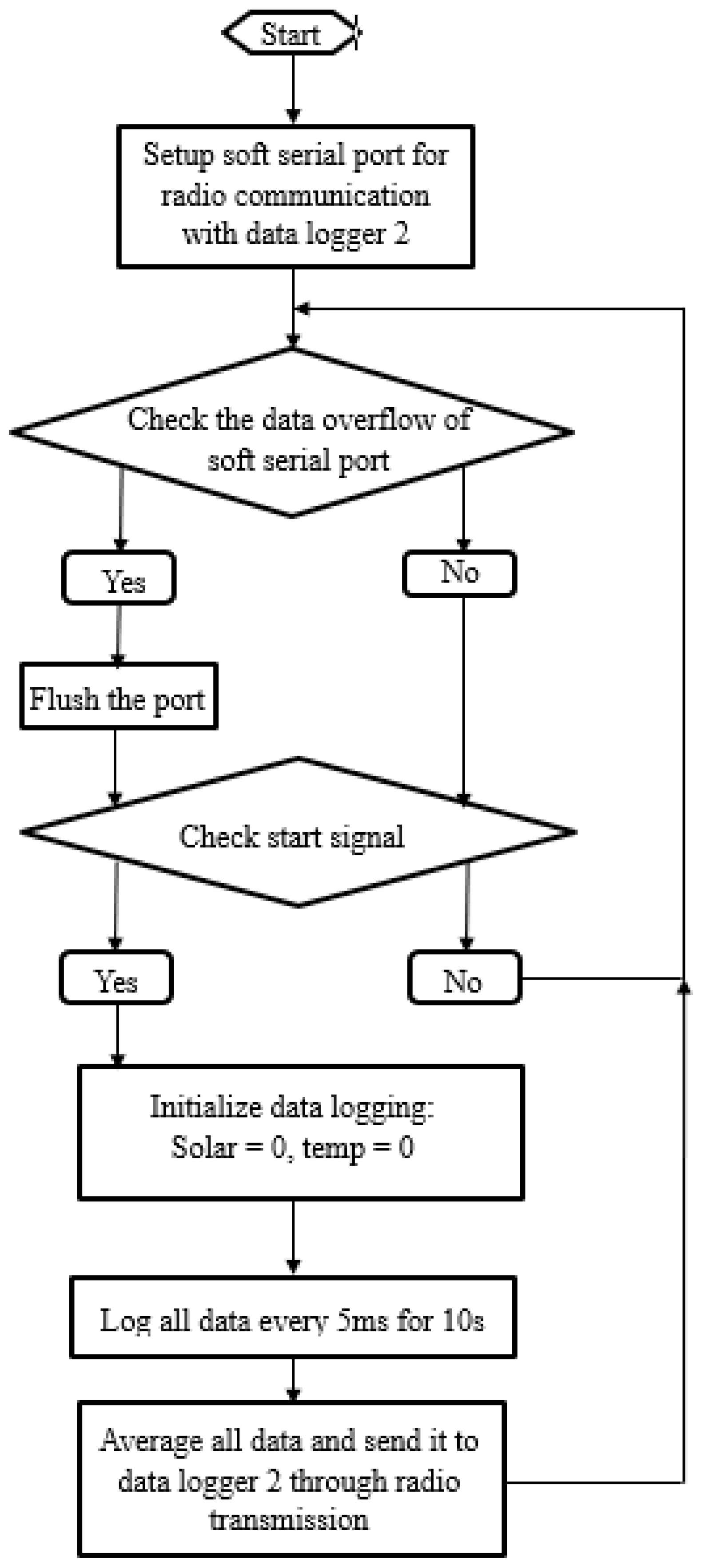
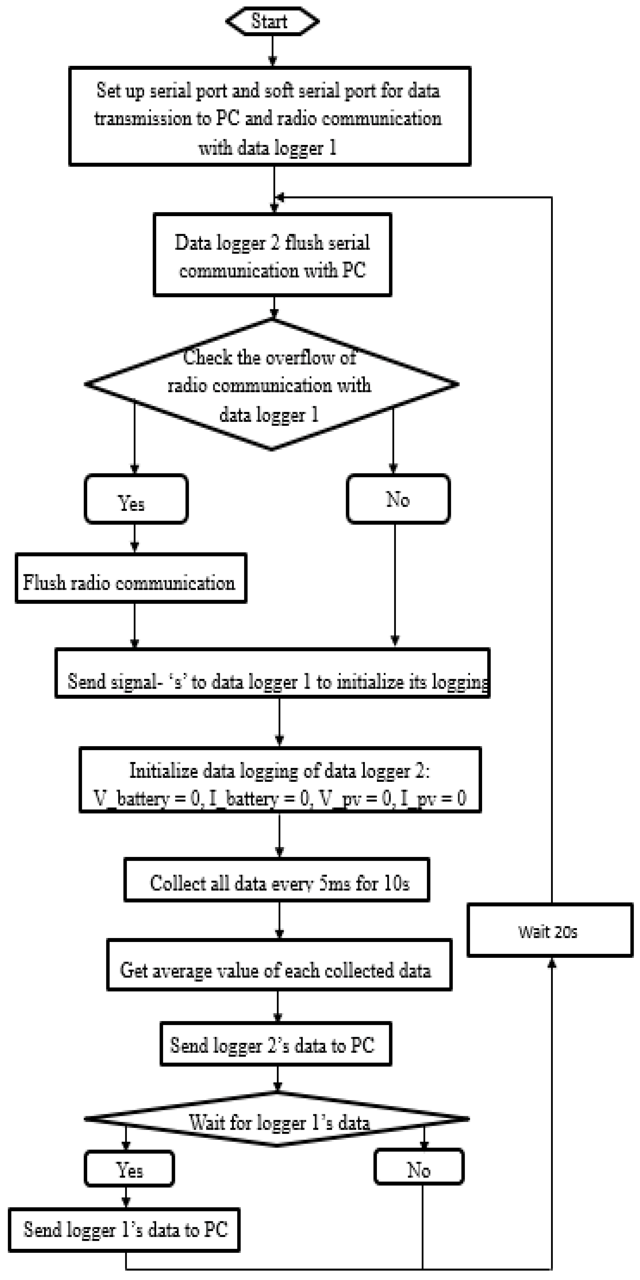
6.1. Program of Arduino Boards (Data Loggers)
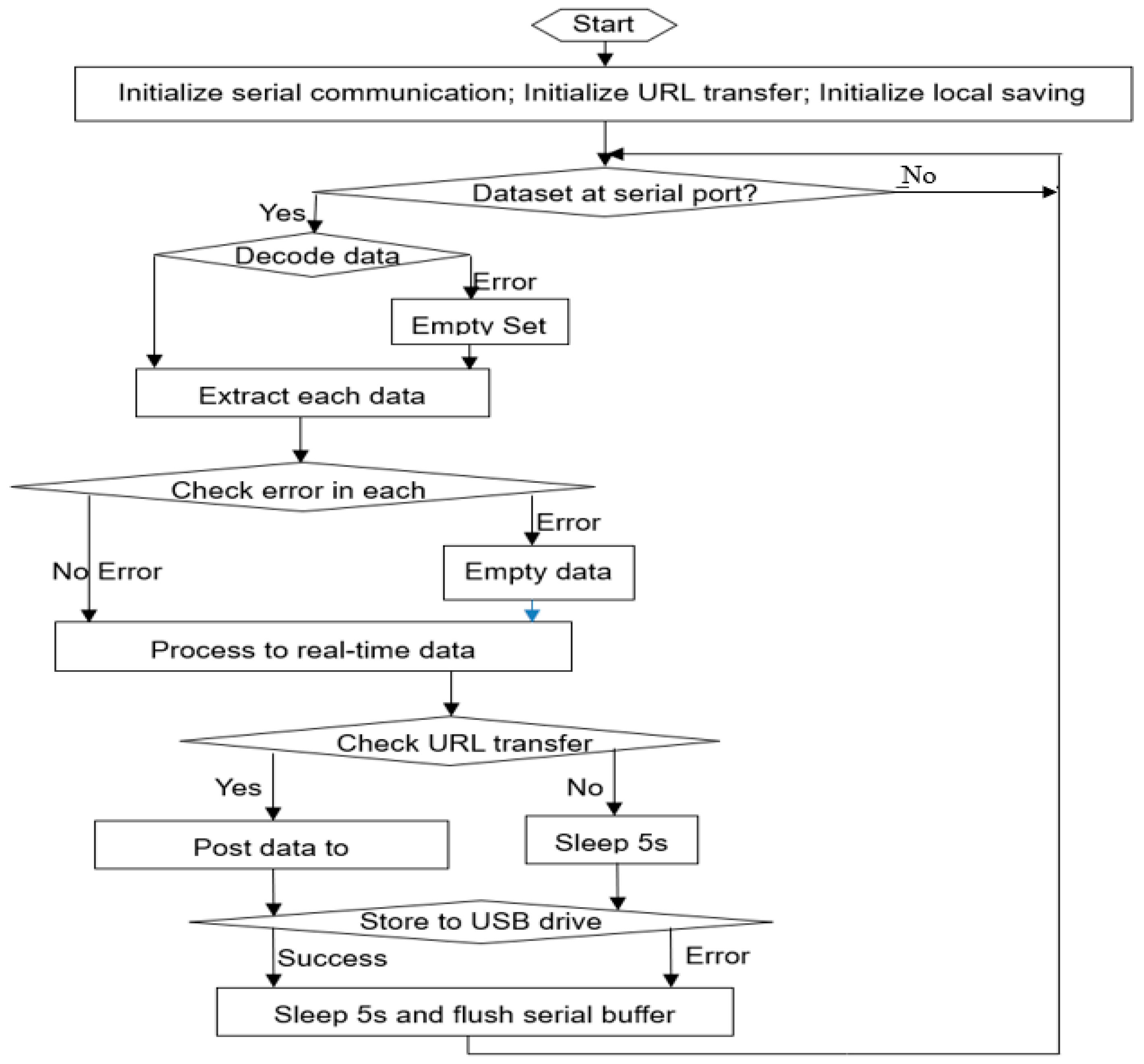
6.2. Python Program on PC
7. Data Visualization and Analysis
7.1. Basic Settings on Thingspeak Server
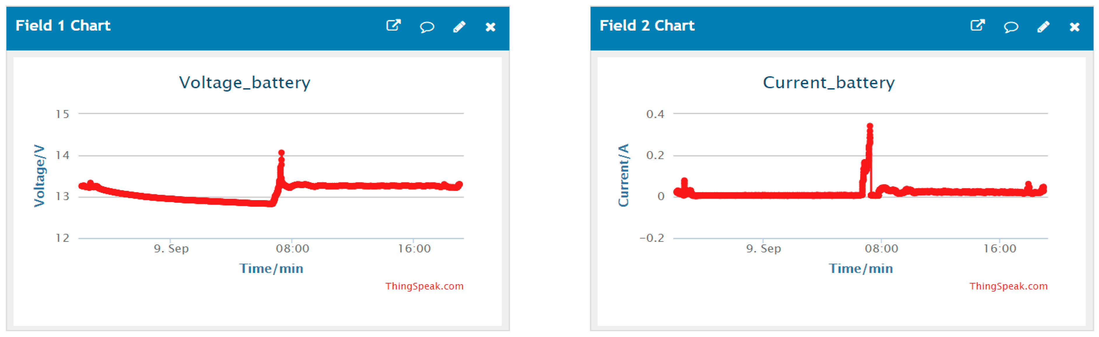
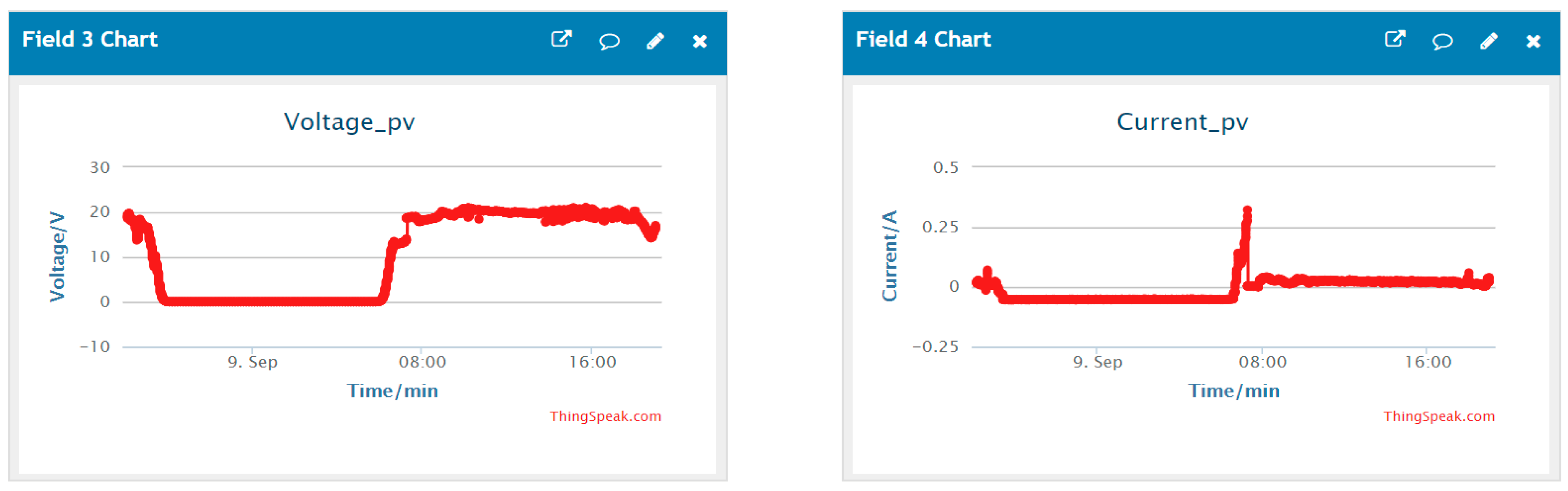
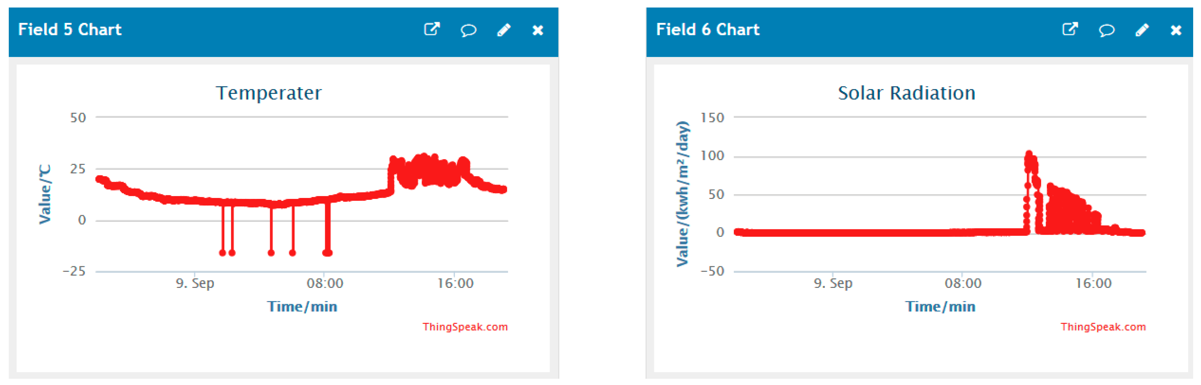
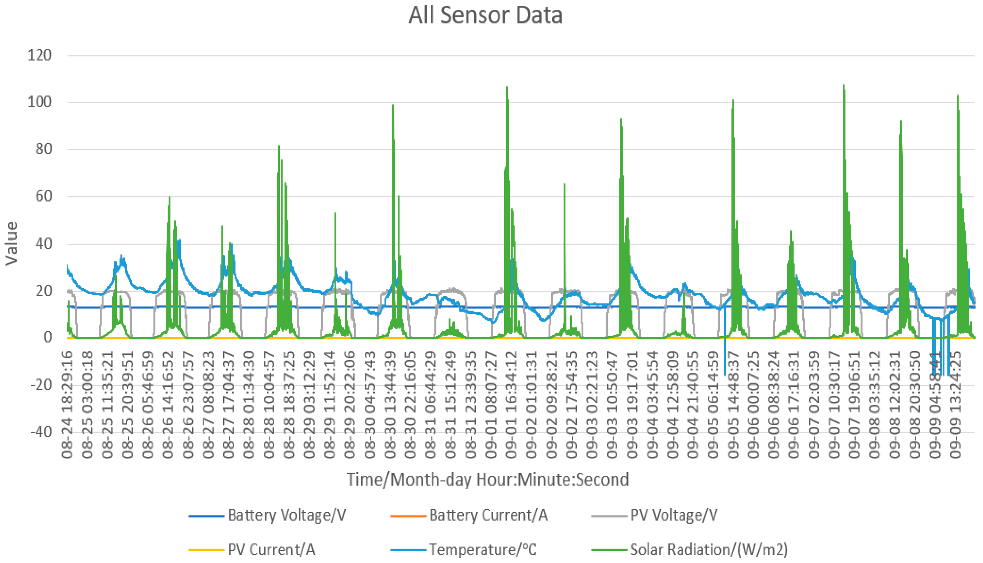
7.2. Data Visualization
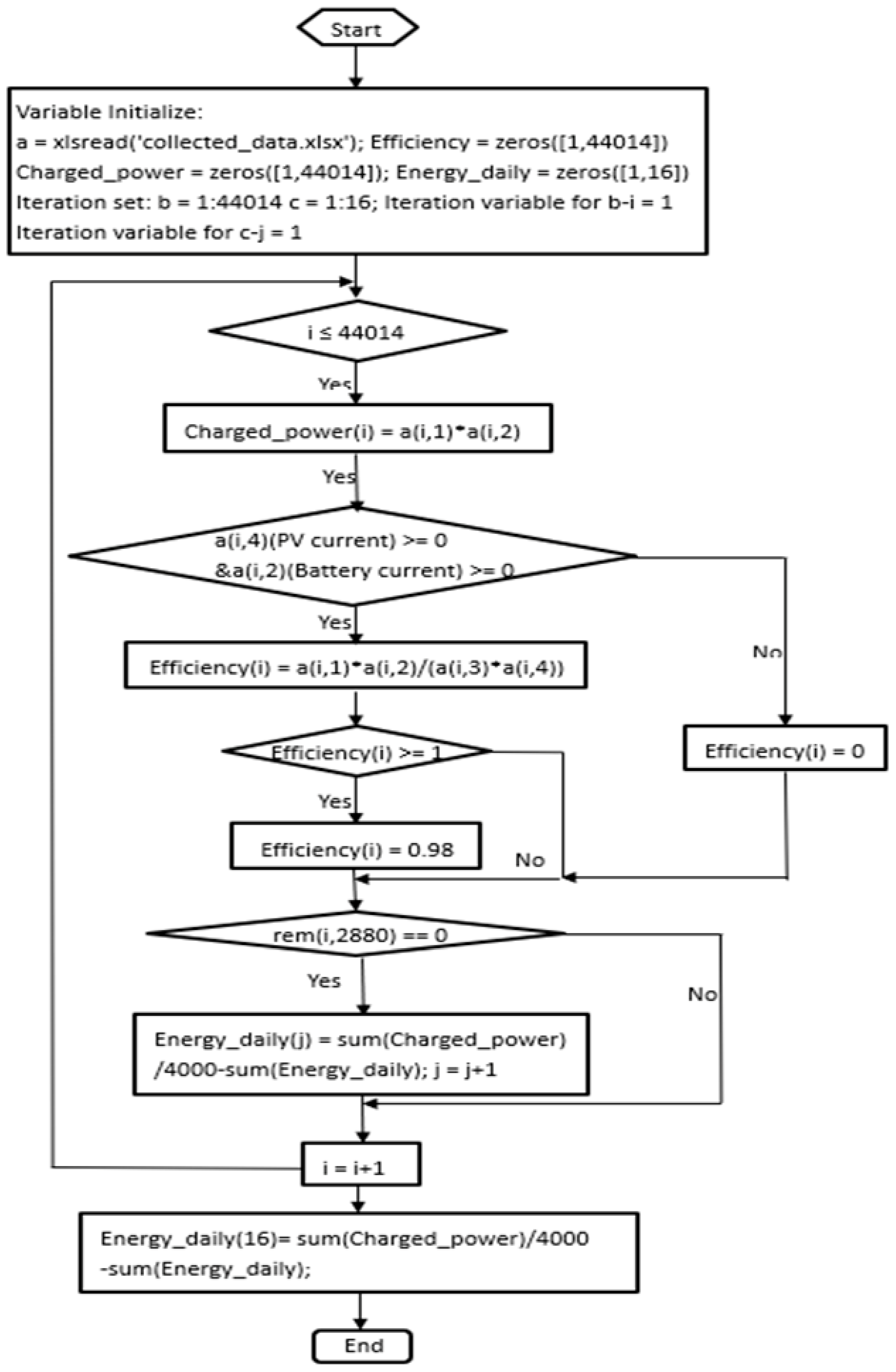
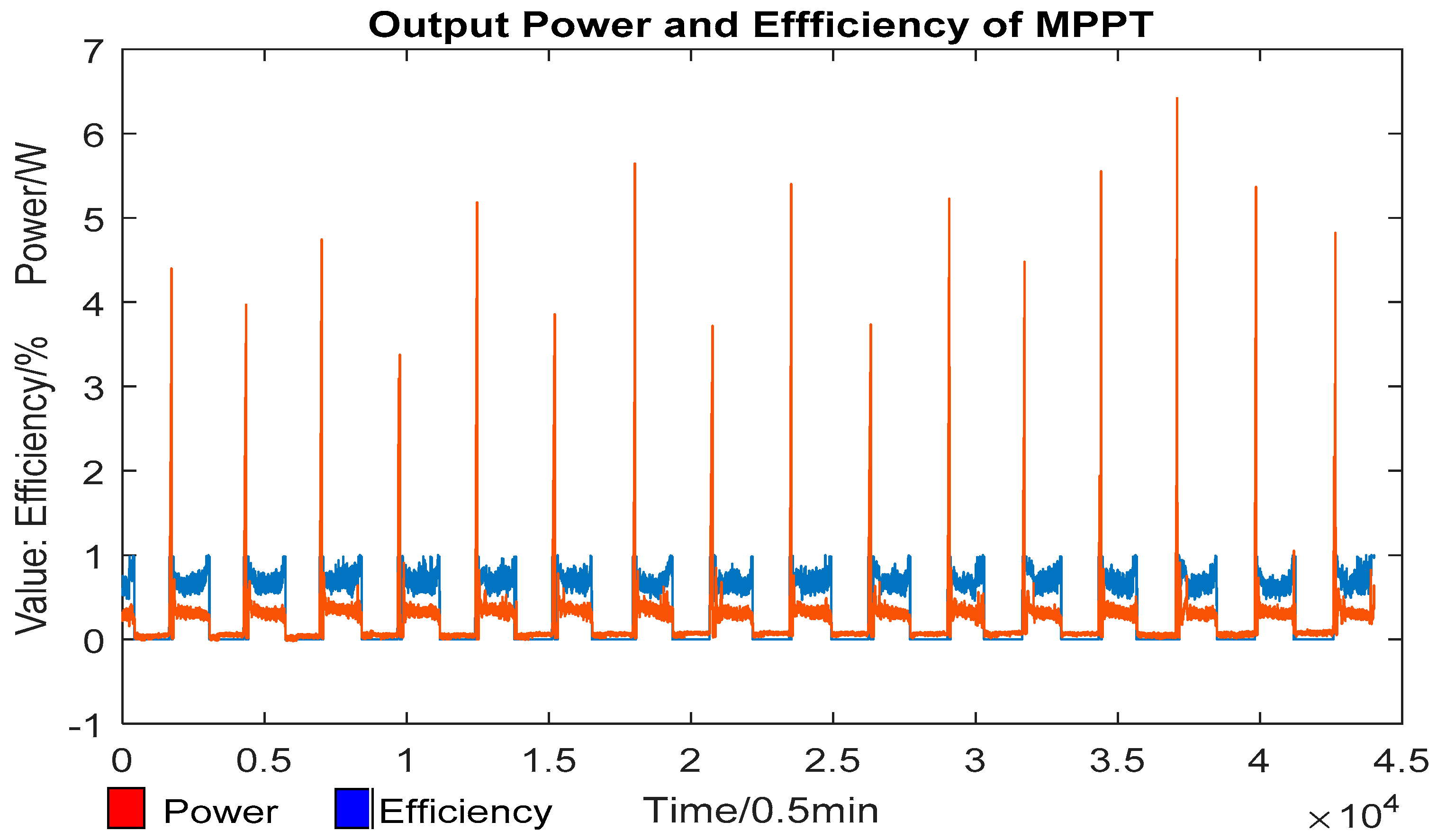
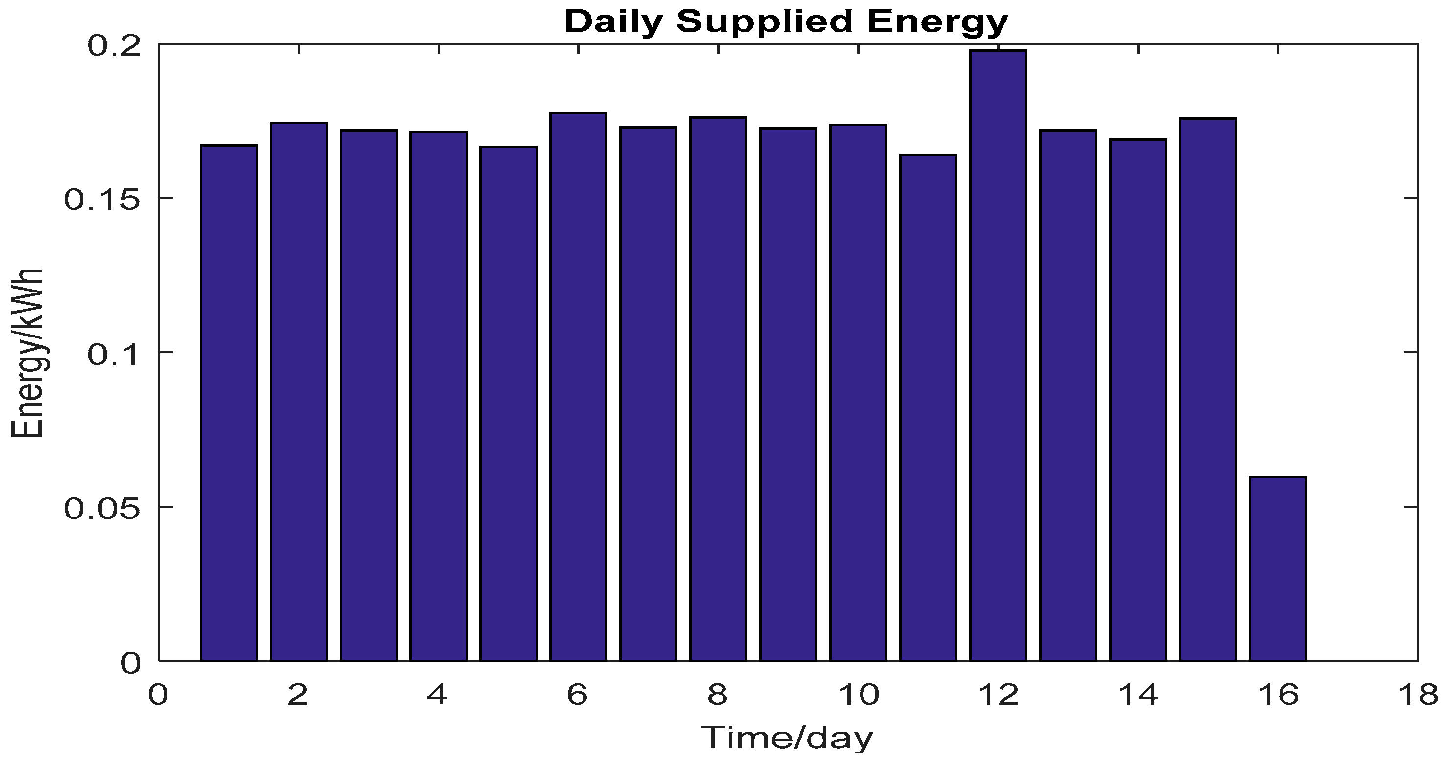
7.3. Data Analysis
8. Conclusions
Author Contributions
Acknowledgments
Conflicts of Interest
References
- Sánchez-Pacheco, F.J.; Sotorrío-Ruiz, P.J.; Heredia-Larrubia, J.R.; Pérez-Hidalgo, F.; de Cardona, M.S. PLC-Based PV Plants Smart Monitoring System: Field Measurements and Uncertainty Estimation. IEEE Trans. Instrum. Meas. 2014, 63, 2215–2222. [Google Scholar] [CrossRef]
- Rezk, H.; Tyukhov, I.; Al-Dhaifallah, M.; Tikhonov, A. Performance of Data Acquisition System for Monitoring PV System Parameters. Measurement 2017, 104, 204–211. [Google Scholar] [CrossRef]
- Munandar, D.; Syamsi, D. Data logger Management Software Design for Maintenance and Utility in Remote. In Proceedings of the 1st International Conference on Information Technology, Computer and Electrical Engineering, Semarang, Indonesia, 8 November 2014. [Google Scholar]
- Ramdan, A.; Astrid, M. Design and Implementation of Data Storage System Using USB Flash Drive in A Microcontroller Based Data Logger. In Proceedings of the International Conference on Automation, Cognitive Science, Optics, Micro Electro-Mechanical System, and Information Technology (ICACOMIT), Bandung, Indonesia, 29–30 October 2015. [Google Scholar]
- Hadiatna, F.; Hindersah, H.; Yolanda, D.; Triawan, M.A. Design and Implementation of Data Logger Using Lossless Data Compression Method for Internet of Things. In Proceedings of the 2016 IEEE 6th International Conference on System Engineering and Technology (ICSET), Bandung, Indonesia, 3–4 October 2016. [Google Scholar]
- Touati, F.; Al-Hitmi, M.A.; Chowdhury, N.A.; Hamad, J.A.; San Pedro Gonzales, A.J.R. Investigation of solar PV performance under Doha weather using a customized measurement and monitoring system. Renew. Energ. 2016, 89, 564–577. [Google Scholar] [CrossRef]
- Available online: https://en.m.wikipedia.org/wiki/Xbee (accessed on 4 April 2019).
- Terashmila Lasagani, K.A.; Iqbal, T.; Mann, G. Data Logging and Control of a Remote Inverter Using Lora and Power Line Communication. EPE J. 2018, 10, 351–365. [Google Scholar] [CrossRef]
- Available online: https://www.topsolarpanel.com/product/sunforce-37130-130w-crystalline-solar-panel (accessed on 4 April 2019).
- Coleman. Coleman 12V 30Amp Digital Charge Controller User’s Manual; Coleman: Wichita, KS, USA.
- Available online: https://www.canadiantire.ca/en/pdp/motomaster-nautilus-group-31-deep-cycle-battery-0103199p.html (accessed on 4 April 2019).
- Allegro MicroSystems, LLC. Fully Integrated, Hall Effect-Based Linear Current Sensor IC with 2.1kV RMS Isolation and a Low-Resistance Current Conductor; Allegro MicroSystems, LLC: Worcester, MA, USA, 2017. [Google Scholar]
- Luna Optoelectronics. CDS Photoconductive Photocells PDV-P8103; Luna Optoelectronics: Camarillo, CA, USA, 2016. [Google Scholar]
- Analog Devices. Low Voltage Temperature Sensors: TMP35/TMP36/TMP37; Analog Devices: Norwood, MA, USA.
- Texas Instruments. MAX232x Dual EIA-262 Drivers/Receivers, 2nd ed.; Texas Instruments: Dallas, TX, USA, 2014. [Google Scholar]
- Available online: https://www.mathworks.com/help/thingspeak/ (accessed on 4 April 2019).


| Input Current (A) | Output Voltage (V) | Average Sensitivity (V/A) |
|---|---|---|
| 0 | 2.487 | 0.187 |
| 1 | 2.671 | |
| 2 | 2.855 | |
| 2.38 | 2.928 |
| Input Current (A) | Output Voltage (V) | Average Sensitivity (V/A) |
|---|---|---|
| 0 | 2.499 | 0.1872 |
| 1 | 2.683 | |
| 1.99 | 2.867 | |
| 2.46 | 2.958 |
© 2019 by the authors. Licensee MDPI, Basel, Switzerland. This article is an open access article distributed under the terms and conditions of the Creative Commons Attribution (CC BY) license (http://creativecommons.org/licenses/by/4.0/).
Share and Cite
Jiang, B.; Iqbal, M.T. Open Source Data Logging and Data Visualization for an Isolated PV System. Electronics 2019, 8, 424. https://doi.org/10.3390/electronics8040424
Jiang B, Iqbal MT. Open Source Data Logging and Data Visualization for an Isolated PV System. Electronics. 2019; 8(4):424. https://doi.org/10.3390/electronics8040424
Chicago/Turabian StyleJiang, Bojian, and M. Tariq Iqbal. 2019. "Open Source Data Logging and Data Visualization for an Isolated PV System" Electronics 8, no. 4: 424. https://doi.org/10.3390/electronics8040424
APA StyleJiang, B., & Iqbal, M. T. (2019). Open Source Data Logging and Data Visualization for an Isolated PV System. Electronics, 8(4), 424. https://doi.org/10.3390/electronics8040424