1. Introduction
Recently there has been a growing interest in unmanned aerial vehicles (UAVs). Their applications are diverse, ranging from surveillance, inspection and monitoring, to precision agriculture and package retrieval/delivery. Landing a UAV is acknowledged as the last and most critical stage of navigation [
1]. According to statistics, the number of accidents associated to the UAV landing process represent 80% of the hazard cases [
2]. Therefore, improved landing techniques are being intensely explored. Furthermore, some of the applications mentioned above, such as package retrieval, require a high level of accuracy so as to make sure the UAV lands exactly on the desired target.
Previous proposals heavily rely on the Global Positioning System (GPS) and inertial navigation sensors (INS) as the main positioning approaches [
3]. However, altitude data provided by the GPS is typically inaccurate and needs to be compensated with a close-range sensor, such as a barometric pressure sensor or a radar altimeter [
4]. Despite such compensation, these methods still remain inaccurate, especially in the horizontal plane, resulting in a landing position that typically deviates from the intended one by 1 to 3 m. Furthermore, the GPS cannot be used indoors. For these reasons, GPS and INS systems are mostly used for long range, outdoor flights having low accuracy requirements [
3].
Taking the aforementioned issues into consideration, the aim of this work is to develop a novel vision-based landing system that is able to make a UAV land in a very specific place with high precision. This challenge is addressed by developing a solution that combines the use of a camera and ArUco markers [
5,
6]. This way, the relative offset of the UAV towards the target landing position is calculated using the ArUco library [
7] (based on OpenCV). After computing its relative offset, the UAV adjusts its position so as to move towards the center of the marker and start descending, performing additional adjustments dynamically.
The rest of this work is structured as follows: in the next section some related works on UAV landing strategies are presented. In
Section 3, our proposed solution is introduced, detailing the methodology followed in order to track the target for landing and how to perform the necessary calculations to adjust the UAV position. Then,
Section 4 provides some technical details about the UAV used to deploy our proposal, highlighting the main issues and restrictions to be taken into consideration in the design of our novel landing algorithm.
Section 5 describes how the different experiments were made. The main results are then presented in
Section 6, where our solution is compared to a GPS-based approach, with an appropriate discussion. Finally,
Section 7 concludes this work and refers to future works.
2. Related Work
Recently, different UAV landing approaches have been studied. These studies can be categorized based on the different types of landing platforms adopted. According to Reference [
8], the vast amount of landing platforms belong to one of these three categories:
Category I–fixed platforms:
Fixed platforms include all platforms that are stationary. This type of platforms are the easiest to land on, since the target remains stationary.
Category II–moving platforms:
Moving platforms are defined by the ability to move with two degrees (surge, sway) of freedom. In this case, the UAV needs to track the platform first and then land on it.
Category III–Landing on a ship:
The ultimate landing platform is on a moving ship. In this case the ship has six degrees of freedom (heave, sway, surge, yaw, roll, pitch) and, therefore, developing a safe landing approach becomes a troublesome task.
It is also possible to categorize the different landing approaches based on the sensor(s) used in the process. Many different sensors can be used, such as sonar, infrared, LIDAR, cameras or a combination of these. Below, some approaches that rely on computer vision will be discussed.
Chen et al. [
9] succeeded in landing a real UAV on an object moving with a speed of 1 m/s (category II). A camera was used to track the position of the landing platform (xy-coordinates) and a LIDAR sensor provided detailed information about the altitude. This research work introduced a robust method to track and land on a moving object. However, the use of a LIDAR sensor discourages the solution, as it tends to be too expensive when scaling to a high number of UAVs.
Nowak et al. [
10] proposed a system in which a UAV could land both at night, as well as during the day. The idea is simple yet robust and elegant: a beacon is placed on the ground. The light emitted from the beacon is then captured by a camera (without a infrared filter) and the drone moves (in the xy-plane) such that the beacon is in the center of the picture. Once centerd, the height is estimated based on the image area occupied by the beacon and the drone’s altitude is decreased in order for it to land safely.
Shaker et al. [
11] suggested another approach: reinforcement learning. In this approach, the UAV agent learns and adapts its behaviour when required. Usually, reinforcement learning takes a lot of time. To accelerate this process, a technique called Least-Squares Policy Iteration (LSPI) is used. With this method, a simulated UAV (AR100) was able to achieve a smooth landing trajectory swiftly.
In the work of Lange et al. [
12] an approach for landing and position control, similar to our work, was developed. Their approach was also based on OpenCV and on recognizing a landing pattern. However, their landing pattern was not built with the use of ArUco markers. In fact, the landing pattern used, with a diameter of 45 cm, was only detected from a distance of 70 cm. Therefore, this strategy cannot be used in an outdoor environment where the flight altitude is typically much higher. However, in this approach, the UAV does not need to see the entire marker, which is an advantage of this scheme.
A system that can land on and track a slow moving vehicle (180 cm/s) was developed by Araar et al. [
13]. Indoor experiments show that the UAV used was able to successfully land on the target landing platform (which also consists of multiple ArUco markers) from a height of approximately 80 cm.
More recently, Patruno et al. [
14] presented a solution for the landing of UAVs on a human-made landing target. Their target was similar to traditional heliplatforms but with specific aspect ratios, so that it can be detected from long distances. The geometric properties of the H-shaped marks adopted are used to estimate the pose with high accuracy, achieving an average RMSE value of only 0.0137 m in pose and 1.04 in orientation.
Baca et al. [
15] were able to detect a moving car at 15 km/h, predict its future movement and attach to it. To achieve it they equipped the UAV with onboard sensors and a computer, which detects the car using a monocular camera and predicts the car future movement using a nonlinear motion model. While following the car, the UAV lands on its roof and it attaches itself using magnetic legs.
De Souza et al. [
16] developed a autonomous landing system based on Artificial Neural Network (ANN) supervised by Fuzzy Mamdani Logic. Their method introduced low computational complexity while maintaining the characteristics and intelligence of the fuzzy logic controller. They validated their solution using both simulation and real tests for static and dynamic landing spots.
Fraczek et al. [
17] presented an embedded video system that allows the UAV to automatically detect safe landing sites. Their solution was implemented on a heterogeneous Zynq SoC device from Xilinx and a Jetson GPU. Differently from the previous works, this work does not rely on a human made marker. Through the use of machine learning and computer vision techniques, the UAV classifies the terrain into three classes. The proposed solution was tested on 100 test images and classified the different terrains correctly in 80% of the cases. Furthermore, in these tests the performance between the Zynq SoC device and the Jetson GPU was compared.
Our work differs from the former ones as we want the UAV to detect the landing area when it is high above the ground (height > 20 m) to compensate for possibly high GPS error values, while using cheap sensors (only a Raspberry Pi camera is needed) and yet still achieving very low errors in terms of landing accuracy (<20 cm). To that extent, only one other source (the Ardupilot community [
18]) was found that is attempting to achieve results similar to ours. Their method follows the same strategy as the work of Nowak et al. [
10], as they also make use of an IR-beacon. According to the ArduPilot authors, their proposed method is able to land a UAV from an altitude of 15 m, reliably under all lighting conditions and with an maximum offset of only 30 cm. While the results of this approach are impressive, ours still outperforms it in terms of both accuracy, altitude and price.
3. Proposed Solution
The aim of this work is to make a UAV land on a specific location. First the UAV has to make a coarse approach to the landing zone. As stated before, the UAV will typically fail to hover above its exact target location, being usually within 1 to 3 m away from the intended landing position. Once the UAV is close to the target location our protocol is activated. The first step deals with finding the marker. The ArUco marker library [
5,
6] (based on OpenCV) provides a function which takes the camera feed and returns information about the marker(s). ArUco markers resemble the well-known QR-codes. They carry less information than the latter ones (only an id), which makes them easier to detect. A typical ArUco marker consists of a black border and a 6x6 square of black and white smaller squares. There are different types of configurations (e.g., 3 × 3, 4 × 4, 7 × 7) known as dictionaries. A marker from a dictionary with less squares is of course easier to detect but only a small number of ids can be provided. In this work, dictionary “DICT_6X6_250” is used. As the name suggests, it provides 250 different ids, which is more than enough for our purposes. The second part consists of descending the UAV while trying to keep it centered over the marker.
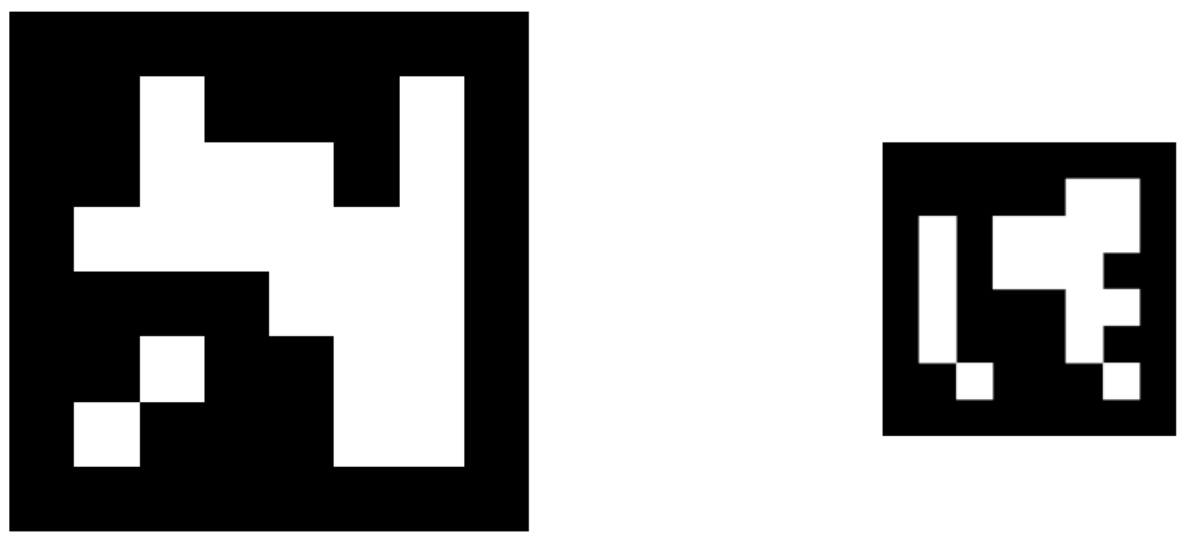
In order to detect a marker two conditions must be met: (i) the marker must be fully inside the picture and (ii) each square must be uniquely identified (black or white). In this application, it is possible that the two conditions are not simultaneously met in some cases. For instance, when the drone is at a low altitude (i.e., 0.5 m) the marker is too big to fit inside the field of view of the camera; in addition, the shadow of the drone may “corrupt” the image. On the other hand, when the drone is flying at a higher altitude (e.g., 12 m) the image may be too small to be detected. Therefore, a strategy was developed that combines markers of different sizes (see
Figure 1), so that the drone can find its target from a higher altitude. If the UAV is able to detect a smaller marker, it will switch to it, adjusting its course accordingly.
Figure 2 shows a real scenario where the UAV is able to see two markers but chooses to move towards the smaller marker. The center of this marker is indicated by the red spot.
Once the marker is detected, the drone has to move towards the center of the marker and descend from there. Due to the effect of wind and to the inherent instability of the UAV itself, the drone will also move in the horizontal plane while descending. This unwanted movement should be compensated in order to land the drone more precisely. To achieve this behavior, the strategy described in Algorithm 1 is proposed, which works as follows: In line 3, the UAV searches for an ArUco marker. If no marker is detected, the flight mode of the UAV is changed to loiter. If this is the case for 30 consecutive seconds, the mission is aborted and the UAV will land using GPS only. Otherwise, from the potential list of detected markers, the marker with the highest ID (i.e., the smallest marker) is selected (line 11). With the use of the ArUco library, the location of the marker with respect to the drone is estimated. If the altitude of the UAV is greater than
(see empirical values in
Table 1),
is set to 20 degrees; otherwise, it is set to 10 degrees. These values are based on: the detection distance of the markers, size of the UAV, size of the markers and a margin which is optimized empirically. In line 20 it is checked if the marker is within the virtual border (explained later). If so, the UAV descends; otherwise, it moves horizontally towards the target position. This algorithm will be executed continuously as long as the altitude of the UAV is greater than
. From the moment the UAV’s altitude drops below
(very near to ground), the control will be handed over to the flight controller, which will land the UAV in a safe manner and disarm the engines.
| Algorithm 1 Static vision-based landing strategy. |
- 1:
Start timer 30 s - 2:
while altitude do - 3:
IDs, detected ← SearchMarker() - 4:
if ¬ detected then - 5:
Loiter() - 6:
if timer exceeded then - 7:
AbortLanding() - 8:
end if - 9:
else - 10:
reset timer() - 11:
ID ← highest detected ID - 12:
Get - 13:
if z then - 14:
- 15:
else - 16:
- 17:
end if - 18:
- 19:
- 20:
if then - 21:
Move(x,y) - 22:
else - 23:
Descend() - 24:
end if - 25:
end if - 26:
end while - 27:
Descend and disarm UAV
|
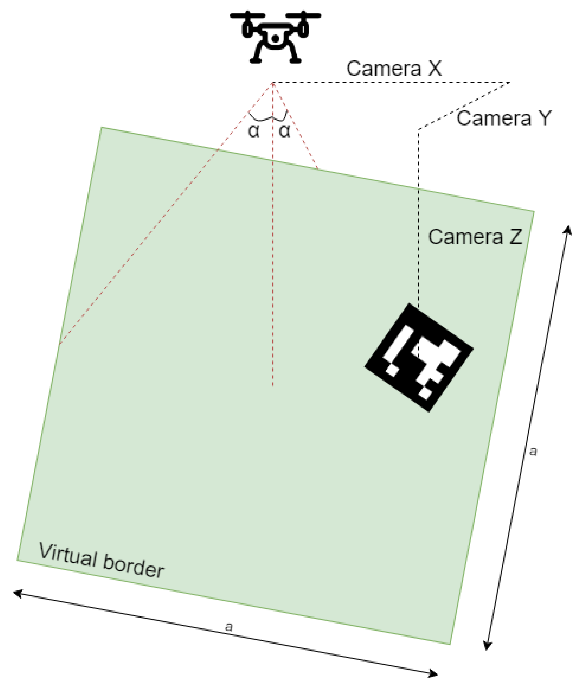
In the description above, a virtual border is mentioned. This border defines an area which should enclose the marker (illustrated in
Figure 3). This virtual border is created in order to distinguish the two cases of descending or moving horizontally. The size
a of this square is defined as:
where
h refers to the relative altitude of the UAV.
The main advantage of defining the area in this way is that it will decrease as the drone lowers its altitude. Therefore, the drone will be more centerd above its target position when it flies at low altitude. However, when flying at higher altitude, the drone should descend whenever possible to avoid excessive landing times. For this reason, is increased to 20 if the UAV is flying above 13 m ().
There are multiple ways to move the UAV towards the target point. In ArduSim, a UAV can be moved for example, by overriding the remote control with function “channelOverride”. With the use of this function the UAV can be moved at a constant speed, first along the roll axis (left/right) and afterwards along the pitch (forward/backward) axis, until the target point is met.
This algorithm experiences difficulties tracking a marker, because it will quickly change between marker IDs whenever one of the markers is not visible for a short amount of time. At first, a small timer was used to eliminate this problem. However, this approach was not satisfactory and so an extension of this algorithm is proposed as Algorithm 2. This second version uses the same general ideas but introduces improvements such as hysteresis that make adjustments more dynamic, achieving a higher effectiveness than the former one. In particular, for this second version, the altitude
(activationLevel[i]) is saved whenever a new marker is detected. Contrary to the former version, the algorithm will only switch between markers when its current altitude is lower than half of the
activationLevel[i] value. With this modification, the typical glitching behaviour (of detecting and not detecting a marker) is bypassed. Furthermore, if the UAV is not able to detect a marker, it will switch to a recovery mode. This means that it will increase its altitude by one meter, thereby increasing the chances of finding the marker again. Finally, the horizontal speed of the UAV depends on the horizontal distance to the marker. The pitch and roll values are set to
(see empirical values in
Table 2) if the distance between marker and UAV is greater then 1 m (see
Table 1); otherwise, it is set to
.
| Algorithm 2 Adaptive vision-based landing strategy. |
- 1:
Start timer 30 s - 2:
while altitude do - 3:
IDs ← Search - 4:
if ¬ detected then - 5:
Recover - 6:
if timer exceeded then - 7:
Abort - 8:
end if - 9:
else - 10:
reset timer - 11:
for all IDs do - 12:
if First time detected then - 13:
activationLevel[i] = altitude - 14:
end if - 15:
if altitude < activationLevel[i]/2 then - 16:
id ← i - 17:
end if - 18:
end for - 19:
Get - 20:
if z then - 21:
- 22:
else - 23:
- 24:
end if - 25:
- 26:
- 27:
if then - 28:
Move(x,y) - 29:
else - 30:
Descend(speed) - 31:
end if - 32:
end if - 33:
end while - 34:
Descend and disarm UAV
|
Since the area captured by the camera is large when flying at high altitudes, there is less risk of missing the marker. Therefore, the UAV‘s descending speed can be varied with respect to its altitude in the following Equation (
1):
4. UAV Specification
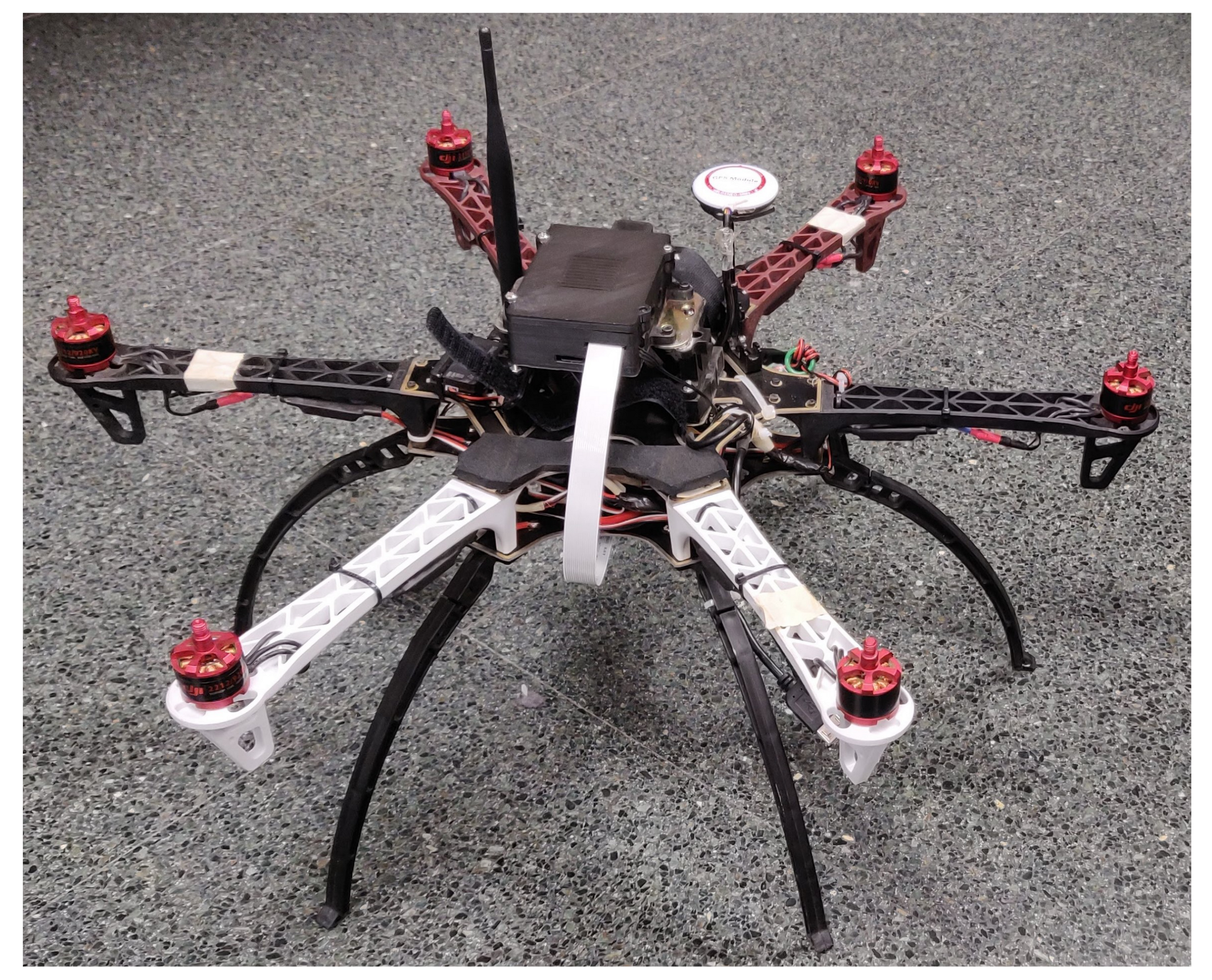
Due to the vast amount and diversity of UAV models available, it is worth mentioning the actual characteristics of the UAV used for our experiments. The UAV adopted belongs to the Vertical Take-Off and Landing (VTOL) category, more commonly known as a multirotor UAV. In the experiments described in this work, a hexacopter model is used (see
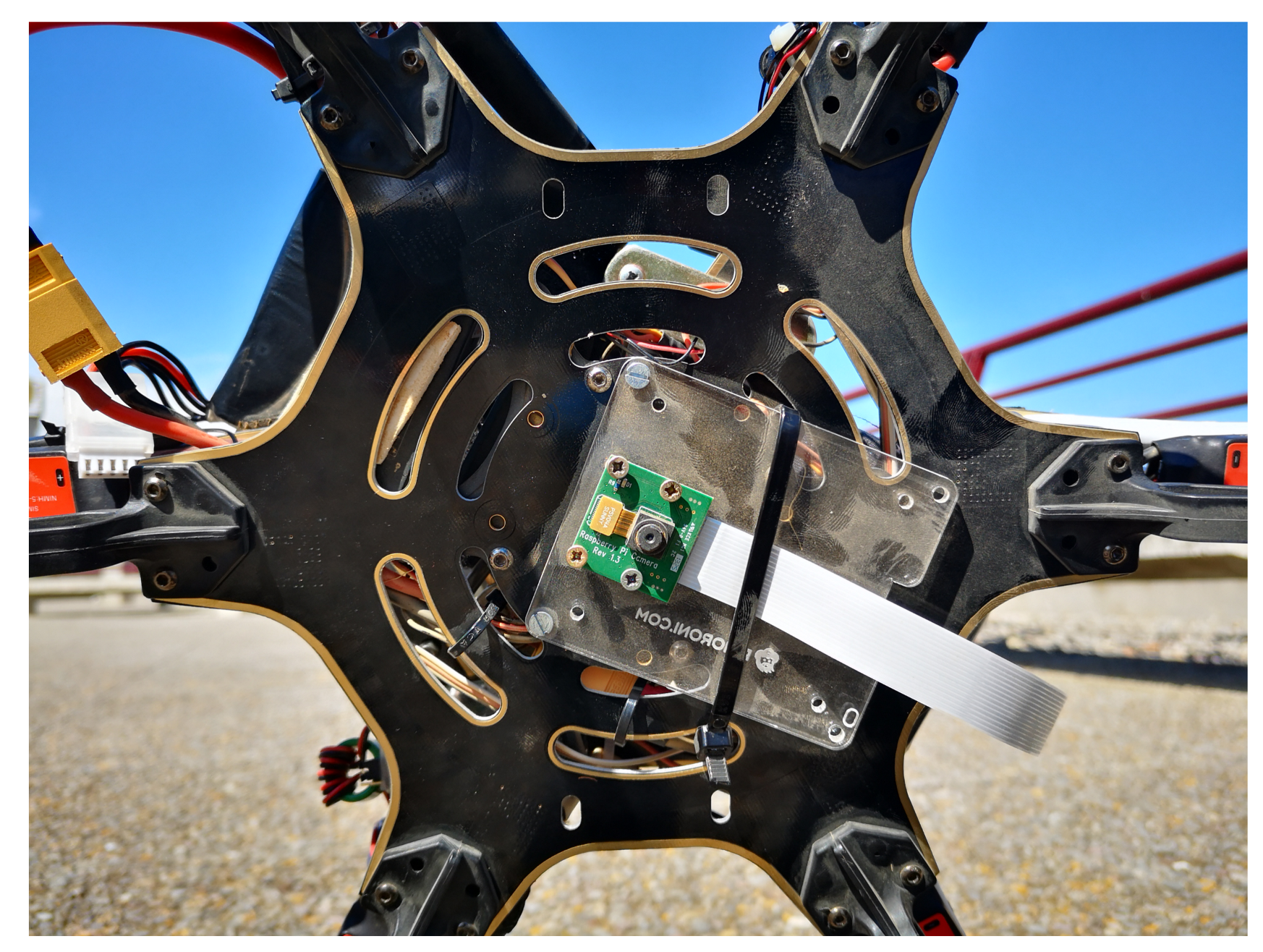
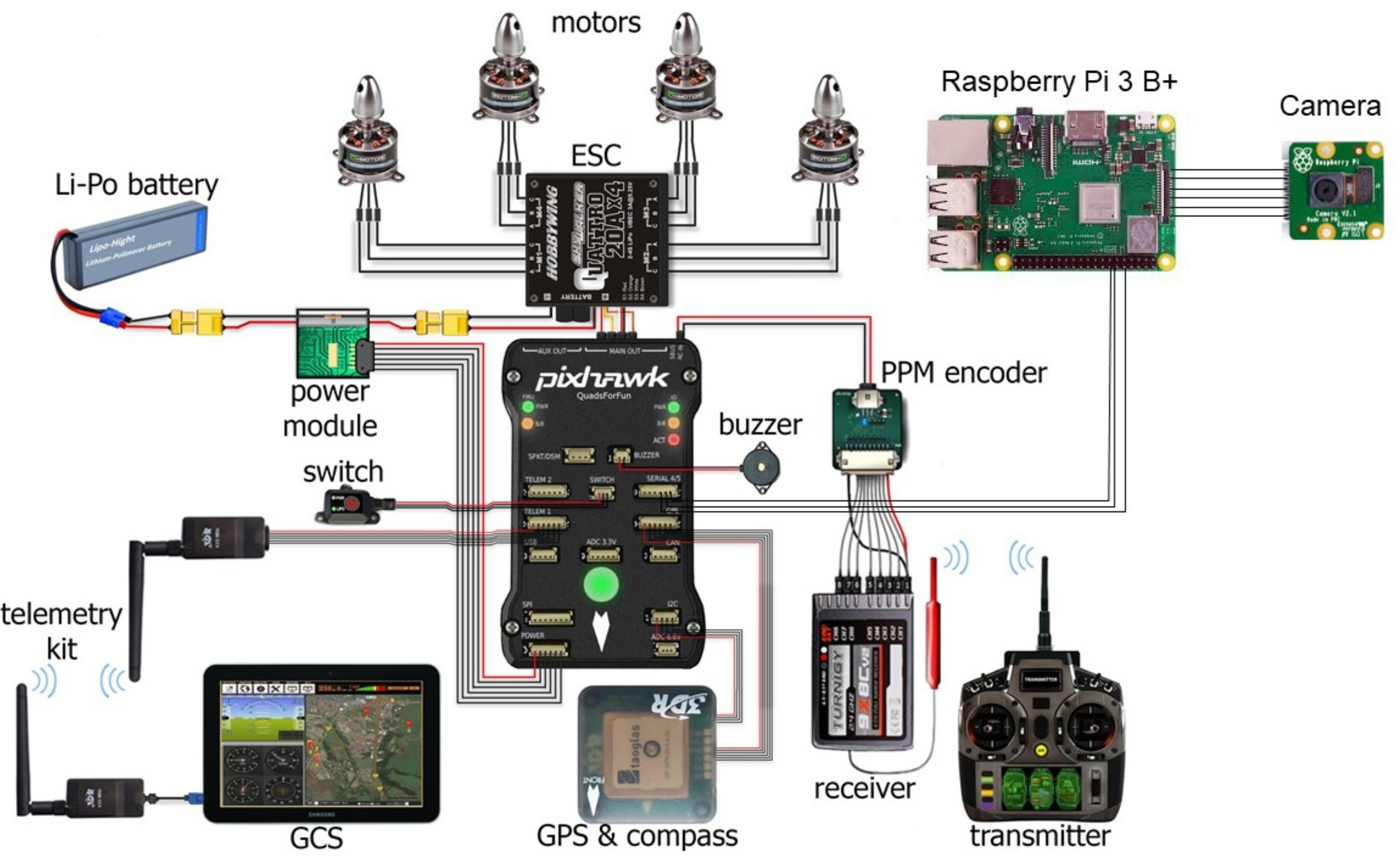
Figure 4), being equipped with a remote control operating in the 2.4 GHz band, a telemetry channel in the 433 MHz band, a GPS receiver, a Pixhawk flight controller and a Raspberry Pi with external camera (see
Figure 5). The Raspberry Pi creates an ad-hoc WiFi connection in the 5 GHz band, which is used to communicate with a ground station or with other UAVs. Below we detail the purpose and the connections (as shown in
Figure 6) between these different devices.
4.1. 2.4 GHz Remote Control
The FrSky X8r receiver provides communication between the UAV and the remote control. This device makes it possible to fly the UAV manually. It receives signals from the remote control and passes them to the flight controller. Furthermore, it sends basic information about the UAV to the remote control for example, flight mode, so that the pilot is informed about the UAV state. It accomplishes these tasks by using the entire 2.4 GHz ISM band. Therefore, it becomes nearly impossible to receive/send any WiFi signal in this band (2.4 GHz), as shown in Reference [
19]. Hence, our ad-hoc WiFi connections rely on the 5 GHz band instead. This 5 GHz WiFi connection is used to connect an UAV or multiple UAVs to the ArduSim ground station.
4.2. 433 MHz Telemetry
The telemetry channel operates at a lower frequency (433 MHz). Its purpose is sending UAV information from the flight controller to a ground station (typically a smartphone), including data such as heading, tilt, speed, battery lifetime, flight mode, altitude, and so forth. It is also able to receive instructions to follow a specific mission, that is, return to home or to perform an emergency landing. However, these set of instructions are very limited since the 433 MHz telemetry is downlink focused. For this reason we have chosen to use the above mentioned 5 GHz WiFi connection to control the UAV from ArduSim. The 433 MHz telemetry will only be used in case of emergency.
4.3. Flight Controller
The flight controller, in this case the Pixhawk 4, is a device that receives information from sensors and that processes this information in order to control the UAV at a low-level, while a Raspberry Pi is in charge of application level control. In particular, information from different sensors such as GPS, barometer, magnetometer, accelerometer and gyroscope are combined in order to provide an accurate representation of the UAV state. This information is then used in order to stabilize the UAV and make it controllable. Some of this information can also be sent via a serial link towards the Raspberry Pi. We opted to use the Pixhawk flight controller (containing an implementation of the Ardupilot firmware [
18]) because it is an open source solution and thus new protocols are easily implemented and deployed on real UAVs. For the communication between the Raspberry Pi and the Pixhawk, the open source MAVLink protocol [
20] is used. It is a lightweight messaging protocol for communicating with most open-source flight controllers, as is the case of the Pixhawk.
4.4. Raspberry Pi
The Raspberry Pi 3 Model B+ serves three purposes in our custom UAV. First, it runs the open source ArduSim [
21] simulation platform, which controls the UAV at a high-level. This program is capable of coordinating an autonomous flight. Second, it also runs a Python application that processes the camera information (see
Figure 5) using the ArUco marker library and sends the resulting information to ArduSim via a TCP connection. Finally, it is used to setup an ad-hoc network in the 5 GHz band. This network can be used to communicate with other UAVs or, in our case, with a ground station (laptop). As an alternative, the Raspberry Pi can be equipped with a 4G LTE dongle so as to operate the UAV from a remote location. However, this option is currently not supported by ArduSim.
4.5. General Components
In addition to the elements referred above, there are mandatory components for each UAV such as:
Electronic Speed Controller (ESC): provides power to motors and controls their speed individually with the use of a Pulse Width Modulation (PWM) signal. The signal needed to vary the motor speed is provided by the flight controller.
Brushless DC motors to rotate the propellers and thus create thrust.
Li-Po battery and power module used to deliver and transmit power to the flight controller, ESCs and all other electrical components.
Safety switch which has to be manually pressed by the pilot to ensure no unintended takeoff takes place.
An optional buzzer to provide feedback about the current state of the UAV.
5. Experimental Settings
Once we finished the implementation of our solution in ArduSim, we performed validation experiments with the multicopter described in
Section 4 in order to assess the effectiveness of our proposed solutions. In the first set of experiments, the UAV was instructed to fly up to an altitude of 20 m, to move toward a specific GPS location and to land automatically (by giving the flight controller full control) once that position was reached. During these experiments, the landing time was recorded, as well as the actual landing position. Those experiments, which do not use our protocol, are used as reference.
In the second set of experiments, the landing accuracy of Algorithm 1 was evaluated. Again, the UAV took off until an altitude of 20 m was reached and then flew towards the target GPS location. The largest available marker ( cm) was placed at that location and the UAV used this marker as the initial reference point for landing. When the UAV was able to detect the smaller marker ( cm), it used that marker as the reference point instead. For these experiments, the descending speed was defined by lowering the throttle by 10% and the roll and pitch values were set to a value of 5%. After each experiment, the landing time and the distance between the marker and the actual landing position were recorded. We define the landing time as the time interval from the moment when the UAV detected the largest marker until the time when the landing procedure was finished.
In the last set of experiments, the landing time of Algorithm 2 was measured. The markers used were the same. However, in this optimized version, the descending, roll and pitch values were dynamic, as described in
Section 3.
6. Results
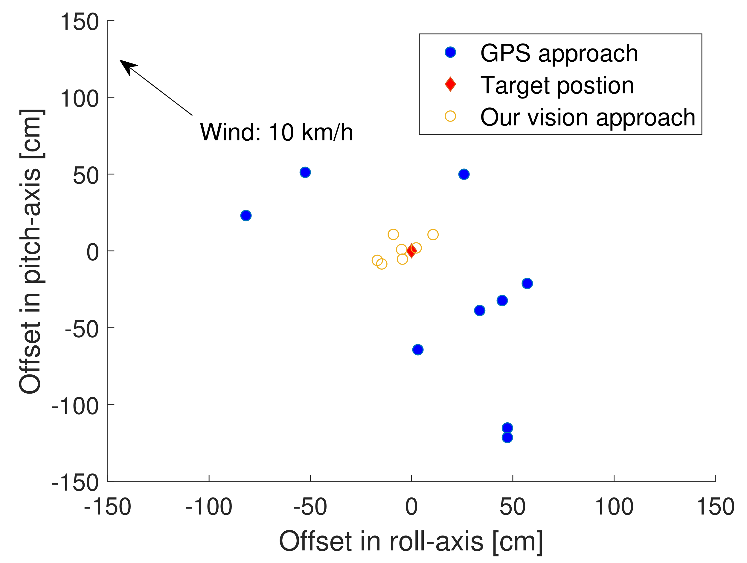
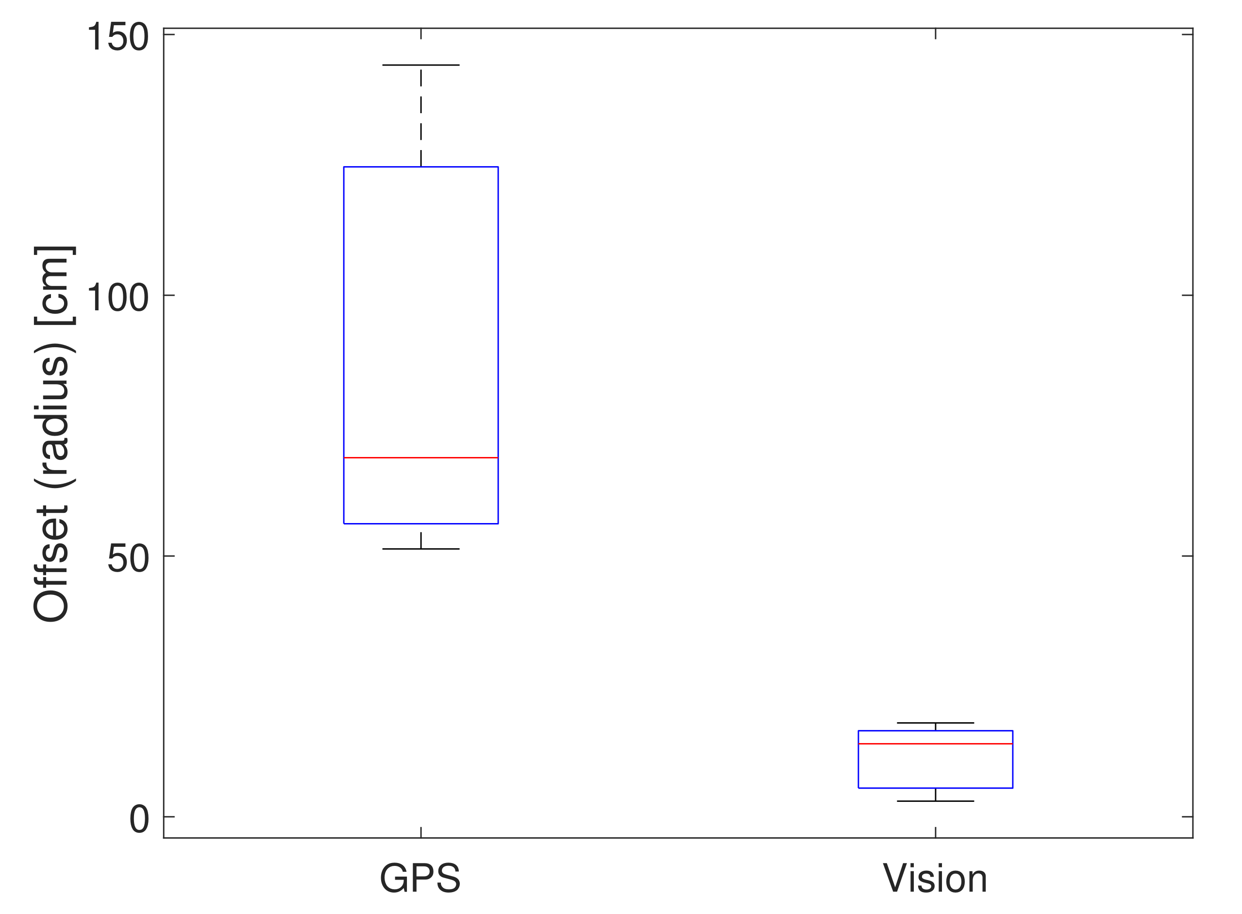
Without the use of our approach, the UAV was able to land consistently within a time span ranging from 27 to 30 s. Nonetheless, this rapid landing comes at a price. As shown in
Figure 7 and
Figure 8, the actual landing position varies substantially, ranging from a maximum error of 1.44 m to a minimum error of 0.51 m; the mean value for our experiments was of 0.85 m.
Notice that these errors are smaller than expected (1–3 m). This is most likely due to the small travelled distance between the takeoff and landing locations. In fact, in these experiments, the UAV flew for only 14 m and the total flight time was of about 52 s. Longer flights will introduce higher errors, as reported in the literature [
22].
As shown in
Figure 7, the landing position accuracy increased substantially when Algorithm 1 was adopted. In particular, experiments showed that the error ranged from only 3 to 18 cm, with a mean value of 11 cm (see
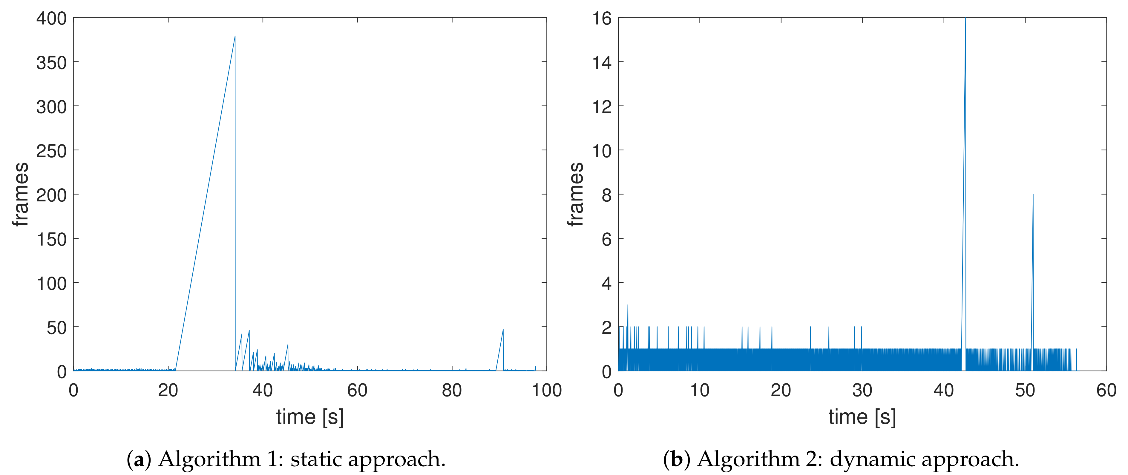
Figure 8). Overall, this means that the proposed landing approach is able to reduce the landing error by about 96%. However, in three out of ten of the experiments performed, the UAV moved away from the marker due to the effect of wind. Since at these moments the altitude was already quite low, the UAV could no longer detect the marker, causing the mission to be stopped after 30 s. Furthermore, the average landing time was increased to 162 s. This is due to the fact that, during the transition from one marker to another, the algorithm experienced problems at detecting the smaller marker during some time periods, as illustrated in
Figure 9a (from second 22 to 35).
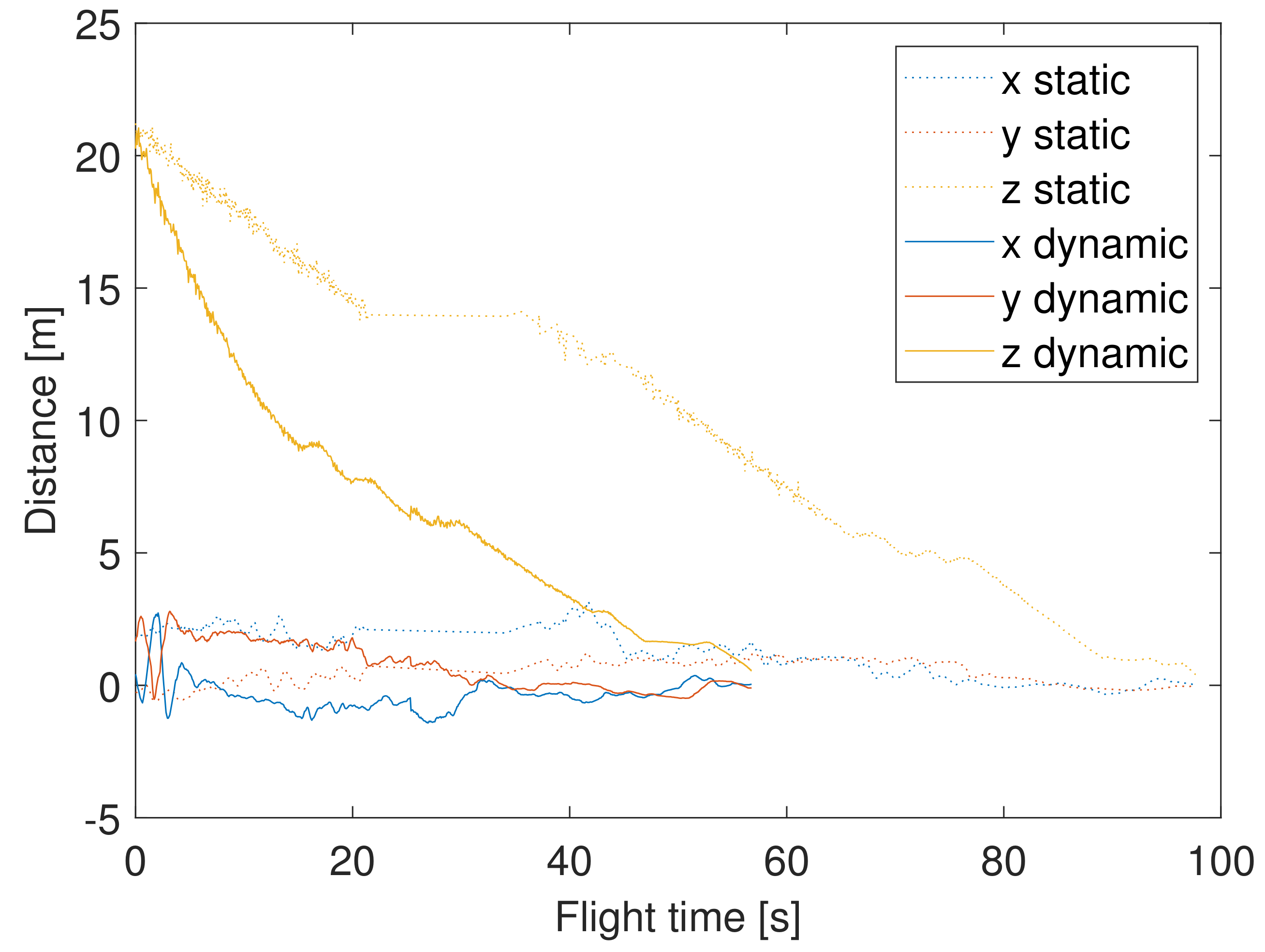
Besides this malfunction situations, the UAV showed a smooth landing trajectory (see
Figure 10).
Notice how the UAV makes more aggressive adjustments in the X axis when the altitude drops below 13 m; this is due to the fact that parameter
becomes smaller, restricting the error range. If the malfunction cases are removed, the average descending speed was of 0.3 m/s, which could be considered too conservative. Furthermore,
Figure 10 shows that most of the adjustments are made when the UAV is close to the ground (constant altitude). This can be better observed in
Figure 11, where the center of the camera frame and the actual location of the marker in regard to both axes is plotted (
,
). It can be seen that the drone only moves when the
or
angle exceeds the value of
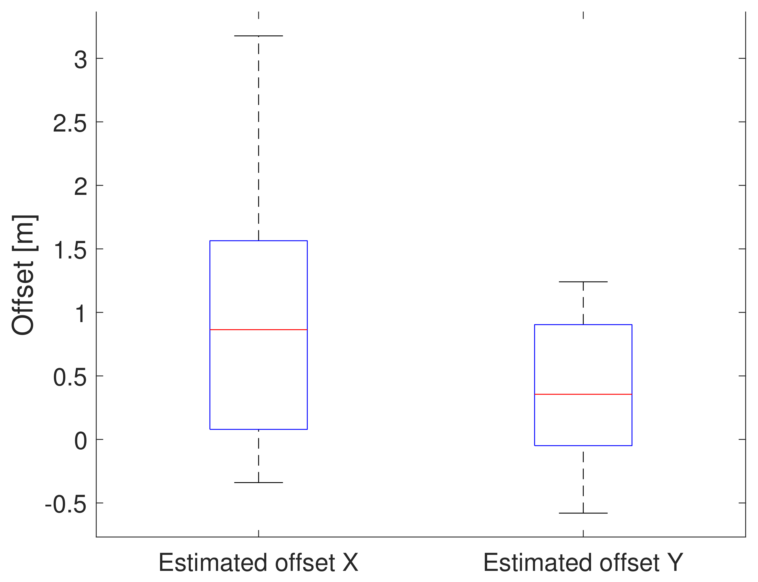
. The range of estimated values captured is shown in
Figure 12; we can observe that there is a higher variability in the X axis due to wind compensation requirements along that direction during the experiments, something that occurs to a much lower extent for the Y axis.
The malfunctions of Algorithm 1 are solved in the second version. As shown in
Figure 9b, Algorithm 2 does not have any issues when switching between markers. Therefore, the landing time is decreased significantly to an average of only 55 s. Furthermore, as shown in
Figure 10, the UAV is descending faster, which also contributes to reduce the landing time. The decrease in landing time did not have any affect on the accuracy of the application. The new recovery mode was also found to be beneficial to ensure that the UAV landed on the marker every time.
To compare the proposed solution to those mentioned in
Section 2,
Table 3 summarizes the results obtained, highlighting the main differences between them.
Finally, an illustrative video (
https://youtu.be/NPNi5YC9AeI) has been made available to show how the proposed solution performs in real environments.
7. Conclusions and Future Work
Achieving accurate landing of multirotor UAVs remains a challenging issue, as GPS-based landing procedures are associated with errors of a few meters even under ideal satellite reception conditions, performing worse in many cases. In addition, GPS-assisted landing is not an option for indoor operations. To address this issue, in this work a vision-based landing solution that relies on ArUco markers is presented. These markers allow the UAV to detect the exact landing position from a high altitude (30 m), paving the way for sophisticated applications including automated package retrieval or the landing of large UAV swarms in a very restricted area, among others.
Experimental results using a real UAV have validated the proposed approach, showing that accurate landing (mean error of 0.11m) can be achieved while introducing an additional (but small) time overhead in the landing procedure compared to the standard landing command.
As future work, it is planned to improve the overall efficiency of the protocol. This can be done by improving the flight behaviour. In addition to decreasing the landing time even further, the accuracy can be increased by integrating the UAV‘s state (acceleration, velocity, etc.) in the control loop. Finally, the algorithm can be further optimized so that the UAV is able to land under less favourable weather conditions.

 ,
, 


