Article

A Novel High-Efficiency Double-Input Bidirectional DC/DC Converter for Battery Cell-Voltage Equalizer with Flyback Transformer

1
School of Electrical Engineering and Automation, Tiangong University, Tianjin 300387, China
2
Center for Engineering Internship and Training, Tiangong University, Tianjin 300387, China
*
Author to whom correspondence should be addressed.
Electronics 2019, 8(12), 1426; https://doi.org/10.3390/electronics8121426
Submission received: 30 October 2019 / Revised: 24 November 2019 / Accepted: 27 November 2019 / Published: 29 November 2019

Abstract

:
Large-scale battery cells are connected in series, which inevitably leads to a phenomenon that the cell voltage is unbalanced. With a conventional equalizer, it is challenging to maintain excellent characteristics in terms of its size, design cost, and equalization efficiency. In order to improve the defects in the above equalization circuit, a novel voltage equalization circuit is designed, which can work in two modes. A bidirectional direct current–direct current (DC–DC) equalization structure is adopted, which can quickly equalize two high or low-power batteries without using an external energy buffer. In order to verify the effectiveness of the proposed circuit, a 12-cell battery 2800-MAh battery string was applied for experimental verification. Computer monitoring (LabVIEW) was adopted in the whole system to intelligently adjust the energy imbalance of the battery pack. The experimental results showed excellent overall performance in terms of equalization was achieved through the newly proposed method. That is, the circuit equalization speed, design cost, and volume have a good balance performance.

1. Introduction

Lithium-ion batteries have been widely used in the field of electric vehicles due to their high charging–discharging times and high energy efficiency. Since the battery pack in a pure electric vehicle is connected in series and in parallel through a large number of battery cells, some of the battery cells may be unbalanced during the continuous charging and discharging process of the battery. The overall performance of the battery pack will be restricted by the battery cells with the lowest battery capacity, which will seriously affect the service life of the battery pack and reduce the battery life of the electric vehicle [1,2]. Battery equalization technology can suppress imbalance in the battery pack, leading to improved work consistency. The battery management system is able to operate well, which can ensure safe driving of new energy vehicles, and the working principle is shown in Figure 1. Excess energy (Converted Energy in the legend) can be transferred from cell 1 to cell 2 through the energy converter. A relatively balanced state is achieved between the two cells, and so on, resulting in consistent energy obtained by the entire battery pack.
In recent years, plenty of battery pack equalization methods have been proposed [3,4,5,6]. The equalization method has been divided into different categories according to various criteria. The energy dissipation has two types [7,8]: switch shunt and fixed shunt. This equalization circuit with a simple structure was easy to control. However, the converted heat will result in increased temperature in the entire battery pack, and the system will require extra energy. Compared with the energy dissipation type, a peripheral energy conversion circuit was applied to balance the voltage of the battery through the non-energy dissipation equalization method. Although the circuit is more complex, it is more efficient and safe according to the different means of energy transmission. These methods are further subdivided into four types: cell-to-cell equalization methods, cell-to-pack equalization methods, pack-to-cell equalization methods, and cell-to-pack to cell equalization methods, as shown in Figure 2.
In the above equalization method, the monomer-to-monomer equalization method and the monomer-to-battery equalization method can effectively prevent overcharging and over-discharging of the battery. Even if the energy overlap and high-pressure stress in the equilibrium process are considered, the equilibrium efficiency cannot be guaranteed. In contrast, cell-to-cell equalization methods with short and efficient transmission paths are ideal choices. These methods are further subdivided into three types: transmission equalization methods, a non-isolated direct current–direct current (DC–DC) equalization method [9], and an isolated DC–DC equalization method [10]. One of the most conventionally used topologies of the transmission equalization methods is the bidirectional buck-boost converter [11]. Every two adjacent cells have a common buck-boost converter to achieve energy transfer. However, when the positions of the unbalanced batteries are not adjacent, the path of energy transfer becomes long. In order to compensate for the shortcomings of such equalization methods, Li, Y proposed a structure of an equalization method [12].
This circuit transfers energy from the most charged unit to the least charged unit to have higher equalization efficiency, but at the expense of lower equalization speed. Another direct cell-to-cell equalization method which uses an inductor as the energy storage component has fast equalization. However, each battery has two directional transmission channels, which require a large number of switches and diodes. Similarly, the direct inter-cell equalization method using a transformer ensures a fast equalization speed [13], but the use of a large number of transformers is costly. Obviously, the aforementioned direct cell-to-cell equalization method cannot achieve fast equalization speed and high efficiency, and relatively low cost.
In order to improve the deficiencies of these defects, a dual-winding battery equalizer with energy bidirectional flow was proposed. The advantage is that the cells with low energy are supplemented, and the cells with high electric quantity are effectively weakened. The principle of operation is an equalization structure using bidirectional forward and flyback equalization. Any two high-energy cells or low-energy cell in the battery pack was quickly equalized without external energy buffer. To realize the effective balance of the whole battery pack.

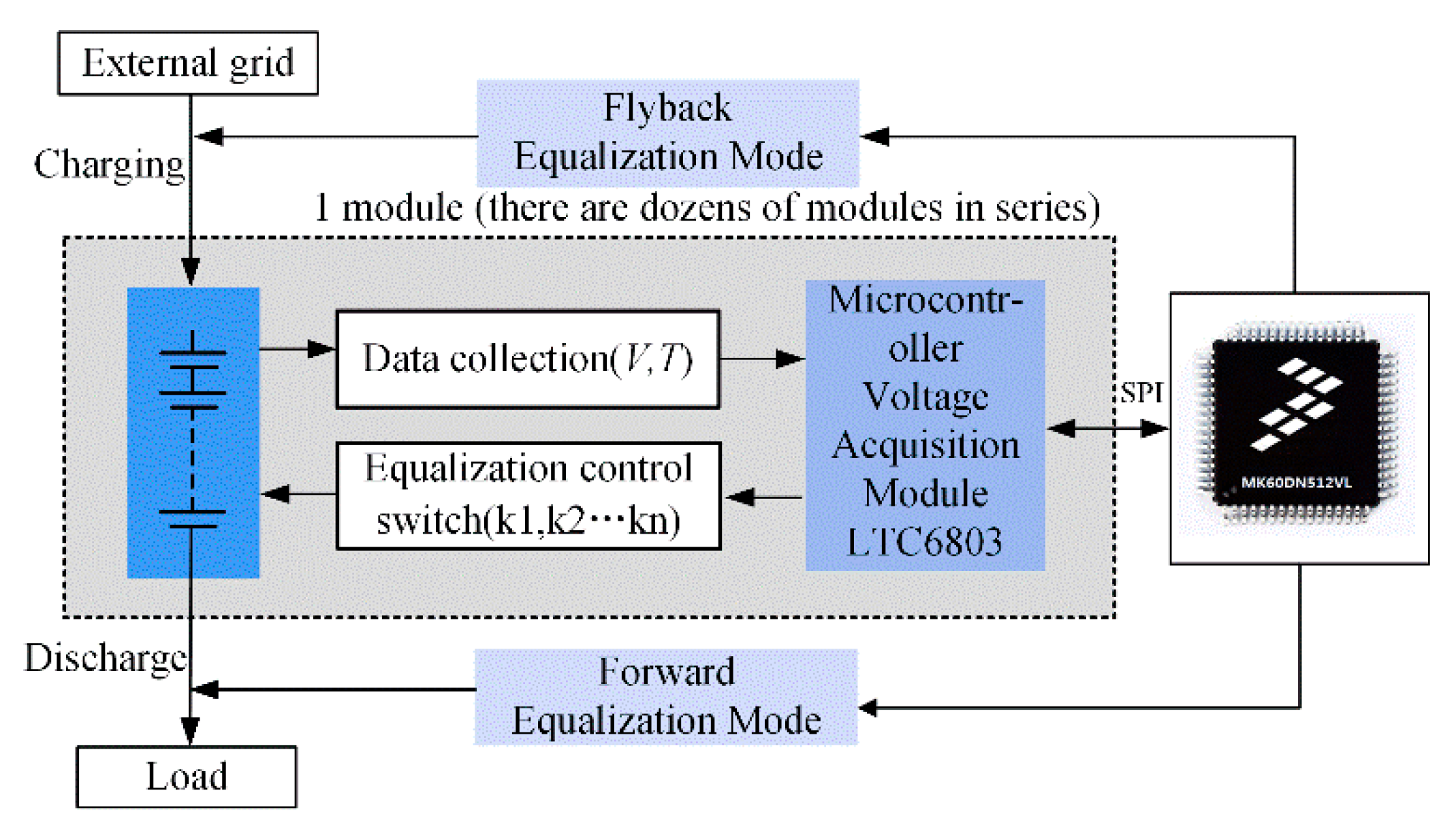
2. Proposed Equalization Topology

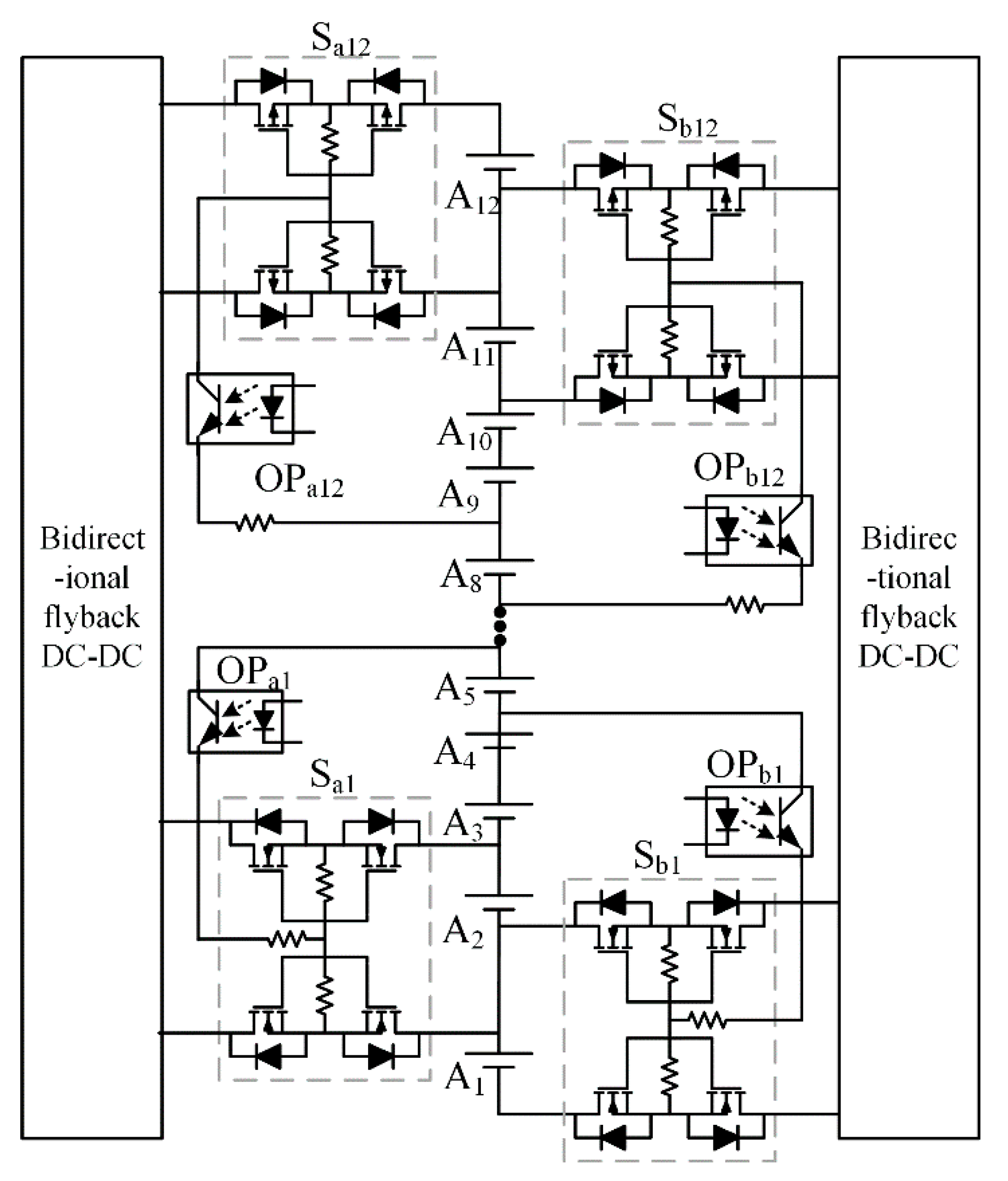
2.1. Proposed Equalizer

The proposed voltage equalizer is composed of a left and right sides interleaved switching network and an isolated double winding DC–DC converter. Figure 3 shows an equalization structure based on a flyback coaxial multi-winding output, which is mainly composed of a flyback transformer T1 and a battery pack B1-Bn circuit. The battery pack as a whole and single cells form a loop through the output winding of each channel. Energy is transmitted to the battery cell from one direction.
The equilibrium method proposed in this paper could be extended from the original single-to-single equilibrium to the multi-to-two equilibrium structure. The staggered switching network is combined with the two operation modes. Bidirectional equalization is realized in the energy-transfer process as shown in Figure 4. The left and right sides are staggered control switches by the application of a two-winding flyback transformer for output isolation. The bidirectional equalization equivalent circuit is shown in Figure 5.
Each cell is connected with a control switch. The control switch K1-K2n+1 is on the left side of the battery pack. The corresponding cell is A1-A2n+1. The control switch K0-K2n is on the right side of the battery pack and the corresponding cell is A0-A2n. The control switch network on the left is connected to the output side winding A2N−1 of the flyback transformer. The control switch network on the right side is connected to the output side winding A2, the battery pack is integrally connected to the L0 end of the flyback transformer.
The flyback mode was applied when the number of unbalanced battery cells in the battery pack increased, which indicated that the energy of the battery pack and the battery cells are directly subjected to two-way energy transfer. There are two kinds of equilibrium situations. One is that the excess energy in the high-power battery cell was transferred to the positive battery pack, eliminating the effect of excessive power. The other is that the energy was provided by the battery cell with low battery capacity, so that the damage of the battery itself induced by over flushing or over discharging of an individual cell can be avoided.
When the energy difference between the individual cells in the battery pack is large, and the equalization mode will adopt forward operation mode, the cell can be directly connected to the A2N−1 and A2 windings on the output side for fast equalization.
The new battery equalizer uses the two modes of operation to work together. Flyback mode is “rough-tuning” and Forward mode is “fine-tuning” synergism, which achieves the goal of efficient and balanced, making efficient use of energy.

2.2. Equilibrium Process Analysis

According to the voltage difference in different single cells as the judgment basis. The equalization method was proposed in this paper to select forward operation mode or flyback operation mode. Finally, efficient and fast equalization of the battery pack was realized, and the specific balancing strategy will be discussed in detail as follows.
Case 1: when the batteries in the group are unbalanced and the voltage difference is large (less than 0.4 V), the operation flyback mode timing is as shown in Figure 6a. In a work cycle, the working process of the flyback transformer can be divided into two stages according to the difference between the control signal and the current path in the circuit. During the process of charging, the energy was transferred from the primary side L0 of the transformer to the secondary sides L1 and L2. The drop of conduction voltage in the control switch is VD1 and VD2. The overall primary side voltage VL0 of the battery pack and the output side voltage are VL1, VL2. The energy was transferred from the secondary side of the transformer to the primary side during discharge.
The following circuit workings in detail were defined as follows: the leakage inductance of the multi-winding transformer is Lk, the magnetizing inductance denotes Lm. In the primary winding of the transformer, the voltage at the input port is VL0, the output port voltage is VL1 and VL2.
V L 1 = ( N L 0 N L 0 ) V L 0
V L 2 = ( N L 2 N L 0 ) V L 0
The coefficient of leakage inductance for VL0 is K, which can be expressed as:
K = L k L m
The energy is transmitted from the primary side to the secondary side, which was shown in Figure 6b. It is divided into the following two modes.
Model 1 (t0~t1): the Q1 switch is turned on, the current Ip in the primary side L0 of the transformer increases. When t = toff, IQ reaches the maximum value. The energy is stored in the magnetizing inductance Lm of the transformer. Where in the exciting inductor current iLM is:
i L m = i L k = V L 0 V D L m + L k t o n
The peak value of the inductor current at the time of ton is:
i p k = i L K I t = t o n = ( V L 0 V D ) D T L m ( K + 1 )
where D is the duty cycle of the control switch. T is the turn-on switching period of the flyback converter, the energy stored E in the transformer is:
E = 1 2 L m i p k 2 = ( V L 0 V D ) 2 D 2 T 2 2 L m ( K + 1 ) 2
In this process, the iron core of the transformer is magnetized. Wherein the increase in the magnetic flux Φ is:
Δ Φ ( + ) = V L 0 N L 0 D t o n  
Model 2 (t1~t2): the Q1 switch is turned off, the secondary side switches Q2 and Q3 are both open. Its current is slowly reduced to Ismin, iD2 and iD3, charge capacitors C1 and C2. The energy in the stored primary side is transferred to the low-energy cell for charge equalization. The secondary inductor current gradually decreases and the falling slope is:
d i L 1 k d t = V L 1 + V D 1 L 1 + L 1 k  
d i L 2 k d t = V L 2 + V D 2 L 2 + L 2 k
In this process, the core of the transformer is demagnetized. The magnetic flux Φ is also linearly reduced, where the reduction Φ is:
Δ Φ ( ) = U L 1 N L 0 ( 1 D ) t o n
The process of turning on and off the energy from the secondary side to the primary side, in principle, is the same as the above process. Therefore, the description is not repeated.
Case 2: when the cells in the group are unbalanced, the voltage difference becomes large (no less than 0.4 V). A forward operating mode was applied in the topology without the output of inductance, considering that the selected battery cells A2N−1 and A2 are monomers with a large difference in power. The circuit topology is shown with the dotted line in Figure 5. The specific working process of this model is analyzed as follows. The working sequence diagram is shown in Figure 7.
(1) Model 1(to~t1): when t = 0, the switch tubes Q2 and Q3 are turned on. The voltages of the battery cells A2n−1 and A2 are applied across the output windings L1 and L2 of the flyback converter, respectively. Battery A2n−1 charges the primary winding Lm1 through Q2 as shown in Figure 5. The voltage across Lm is VA2n−1-VD2 where the direction is up and down. Meanwhile, the induced voltage across the winding Lm2 is VA2n-1-VD2 due to the coupling relationship of the voltage transformation, its direction is up and down. A peak current of I0 was produced from the secondary winding circuit under the turn-on instant. The core is magnetized and the magnetic flux is maximized during this process. The current on winding L1 and winding L2 increases and the voltage across the battery is directly parallel balanced.
I 0 = V L 1 V D 1 V A 2 R e q
where Req denotes the equivalent resistance of the battery A2 loop, then the voltage across the secondary winding L2 is clamped at VA2 + VD2. The inductance current in the circuit decreases linearly.
Its slope is:
d i L 2 k d t = V A 2 + V D 2 L 2 + L 2 k
During the period of t0-t1, the currents of windings L1 is:
i L 1 ( t ) = I 0 V A 2 N 1 + V D 1 L 1 + L 1 K ( t t 0 )
At time t1, the bidirectional switches Q1 and Q2 are turned off. The mode ends and the current of the winding L1 at time t1 is:
i L 1 ( t 1 ) = I 0 V A 2 N 1 + V D 1 L 1 + L 1 K D T
The current of the primary winding at time t1 is:
i L 1 k ( t 1 ) = I max + V A 2 N 1 V D 1 L 1 m ( 1 + K ) D T
The energy stored in the transformer at this time is:
W L 1 m = ( V A 2 N 1 V D ) 2 2 L 1 M ( 1 + K ) 2 D 2 T 2
(2) Model 2 (t1~t2): at t = ton time. Turn off the switch tubes Q2 and Q3. Switch tubes Q2 and Q3 is turned off when t is at ton. There is no current flowing through the winding L1 and L2. At this point, the transformer conducts magnetic reset through the reset winding. The excitation current is fed back to the whole battery pack through the primary side. Finally, the reset of the magnetic flux is realized.
d i L 2 k d t = V A 2 + V D 2 L 2 + L 2 k
i L 2 ( t ) = I L 2 ( t 1 ) V A 2 + V D 2 L 2 + L 2 K ( t t 1 )
At this point, the energy is completely transferred at time t2. The current iL2(t) becomes zero and the transformer completes the magnetic reset.

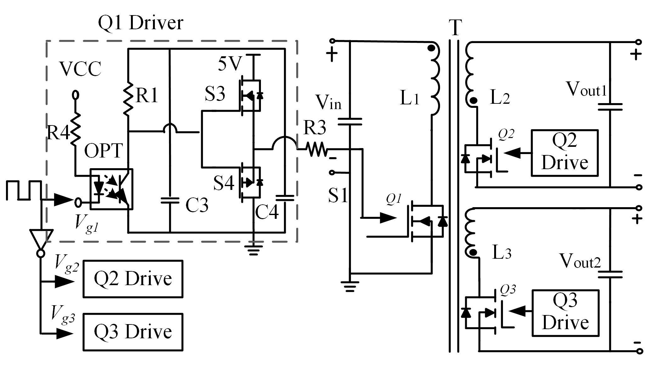
2.3. Design Consideration of the Main Circuit

This article uses a two-winding bidirectional flyback converter. Whether energy is from Vin to Vout, or energy is from Vout to Vin, the switch Q1 is turned on when the diode D1 opposite to it is energized. The switch tube Q2 is turned on. When the D2 is energized and all the zero-voltage switching (ZVS) are turned on. In the bidirectional flyback converter, the current alternates and the current work continuously. Let Q1 have a duty cycle of DQ1. When the energy flows Vin to Vout1, the input voltage and output port voltage are expressed as:
V I N V o u t 1 = L 2 L 1 × D Q 1 1 D Q 2
If DQ2 is the duty cycle of Q2, when energy flows from Vout1 to Vin1:
V o u t 1 V i n 1 = L 1 L 2 × D Q 2 1 D Q 1
Assuming that the input voltage Vin is 30–45 V, the output voltage Vout is 3.8–5 V and the switching period T is 40 μs. And then the duty ratio D can be derived to be 68%. The average equalization current Ipk is calculated to be 1.52 A.
The peak equalization current is expressed as follows:
I p k = 2 P i n D max V in min
The input power is expressed as follows:
P i n = p 0 E f f = U o u t 1 × I w 1 + U o u t 2 × I w 2 E f f
Considering the energy storage and conversion of the flyback converter. The primary inductance is expressed as follows:
L m = V in min × D max I p k × f s K R F = V in min × D max ( 2 P i n D max V in min ) × f s K R F = ( V in min × D max ) 2 2 P i n f S K R F
The flyback transformer is equivalent to a coupled inductor. In the process of transferring energy from the primary side to the secondary side, because the coil has magnetic flux leakage the magnetic flux leakage energy cannot be transferred to the secondary party thereby causing the switching tube voltage to rise further. The clamp circuit connected to the primary and secondary sides of the bidirectional flyback transformer. This limits the switching tube voltage to the maximum value. This article uses the RCD (Resistance Capacitance Diode) absorption circuit, as shown in Figure 8.
R C = V C 2 P R = 2 × V C 2 L i K I P 2 f s
C C V C Δ V C R C f s
The clamp capacitor C has the same voltage as the resistor R. The relationship between R and C can be obtained by the relationship between voltage and power transition. According to the above analysis, during the working process of the clamp circuit, the energy stored in the capacitor is consumed by the resistor. That is, the power consumed by the resistor is equal to the energy stored by the capacitor.

2.4. Equalization Strategy

The new voltage equalization structure was proposed in this paper. During the process of equalizing the battery pack, it is necessary to control the DC–DC converter in different operating modes. This can become an essential basis for working mode matching by the amount of cell voltage difference. Meanwhile, the corresponding control method was adopted to control the equalization switch network. The balancing strategy is shown in Figure 9. The strategy of equalization control should pay attention to the following points:
A. Selected battery port voltage as a criterion for equalization.
B. In the process of energy transfer, when the current is not zero, it will cause irreversible losses to the elements of the switch array in the long-term equalization process.
C. Balanced operation modes are divided into two types, which are switched according to the distribution of different battery voltages.
For A: the equalization control uses the battery port voltage as a reference. The equalization mode is selected according to the voltage dispersion degree of different unit cells. The highest voltage and the lowest voltage of the battery cells are Vmax and Vmin, and the difference between them is Vd. The difference between the voltages is:
V d = V max V min
For B: when the switch network is switching. It is necessary to keep the flyback isolation converter off. Prevents damage to circuit components, which is caused by inrush current during switching.
For C: when the allowable difference Vd set by Vd is equalized, the balance is stopped until Vd is less than Vd. The specific equalization process is played by two working modes, which will be described in detail below as follows.
Flyback mode: the problem of the voltage difference Vd has been addressed when this difference of each battery in the battery pack is no less than 0.4V. The battery pack as a whole was applied as energy input and only the battery pack was used as energy output through the flyback mode of operation. Due to the special two-winding output structure. The battery pack can simultaneously charge balance two low-power batteries, or two high-energy batteries can be fed as energy input for the entire battery pack.
Forward mode: when the pressure difference Vd of each cell in the battery pack is less than 0.4V, in forward mode select two low-power battery cells by connecting the two output windings of the transformer. Point-to-point supplementation of energy for fast balancing purposes.

3. Experimental Results

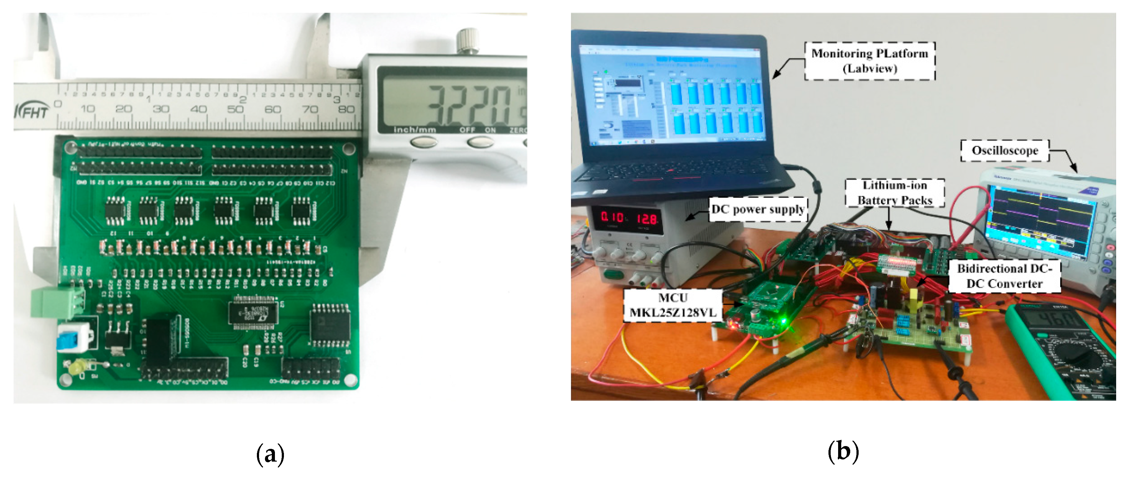
3.1. Voltage Equalization System

Figure 10 shows the structure of the voltage equalization system designed by the new voltage equalization structure proposed in this paper. Because the car power battery pack is composed of series batteries. Therefore, this article uses 12 battery cells in series for voltage equalization experiments. the battery voltage of the series can be monitored in real-time using the battery detection chip LTC6803. The main control unit communicates with the LTC6803 through SPI (Serial Peripheral Interface) to obtain the voltage of the battery cells of the battery pack and control the LTC6803. The master passes the output control signal. The LTC6803 controls the two-sided interleaved switching network through the S1, S2, S3...S12 pins. The master provides control and drives signals for the flyback isolation converter.

3.2. Main Circuit Design

In the new voltage equalization system, real-time acquisition and analysis for parameters of battery voltage and temperature parameters were performed by the main controller and voltage detection chip LTC6803. Different equalization modes are selected according to the number of unbalanced monomers, thus the equalization control was efficiently implemented. The switch array has a function of selecting a path, and the battery cells are connected to the double-winding flyback isolating converter by the switches on the left and right sides. The switch consists of a bidirectional MOS (Metal-Oxide-Semiconductor) tube. The six cells A1, A2, A3, A4, A5 and A6 at the bottom of the pool group are connected to the N-MOS (N-Metal-Oxide-Semiconductor) switch tube respectively. The left battery cells A7–A12 are connected to the P-MOS (P-Metal-Oxide-Semiconductor) switch tube, the specific working circuit is shown in Figure 11. The battery cell is connected to the switch tube through the optocoupler, the switch is connected to the gate of four MOS transistors, the first four switches of the battery pack are Sa12, Sb12, Sa11, Sb11, the gate of each set of switches is connected to the c-pole of the phototransistor in the optocoupler, the e pole is connected to the negative electrode of the battery cell, which possessed the lower three positions of the battery cell. For example, the switch corresponding to the battery unit A12 is Sa12. The gate of the four PMOS transistors is connected to the c pole of the optocoupler OPa12, and the e pole is connected to the negative electrode of the battery unit A9. The switch corresponding to the A1 battery cell is OPb1 on the right side in the switch array, the gates of the four N-MOS transistors are connected to the e-pole of the optocoupler OPb. The c pole is connected to the battery cell A4. The connection method is the same as the above discussion when the control switches of the remaining battery units are applied. An additional complicated switch drive circuit is not required for the structure, the driving voltage of MOS is directly provided by the battery pack, the optocoupler is connected to the left and right switch arrays for signal control, which acts as a signal isolation function, the battery structure is simple and efficient.
The circuit of the flyback isolation converter is shown in Figure 12. The output winding of the flyback converter is connected to two battery cells of different potentials in the battery pack. The corresponding equalization mode was adopted through different modes. The isolation between the battery pack and battery can be realized by the flyback transformer T. The optocoupler OPT, MOS transistor S3 and S4 formed an isolation driver. The 5V power supply was provided by an isolated power supply. Current is detected by current sensor ACS712. The control switches in the circuit are Q1, Q2, Q3 respectively. If switch Q1 is turned on, meanwhile Q2 and Q3 are off, and the duty cycle PWM pulse can be adjusted by the main controller according to the output of the equalization circuit. The signal that controls the output was divided three ways: one way was to control Vg1 and the two external signals were connected to one inverter to control the opposite signals of Vg2 and Vg3. The driving circuits of Q2 and Q3 shown in Figure 12 are the same as the working principle, which thus was simplified in the circuit diagram.
When the input signal Vg is high, the LED (Light Emitting Diode) in the optocoupler did not work. The phototransistor is turned off, resulting in a high-level output of optocoupler. Drive control MOS tube S3 is turned on, and S4 is turned off. The output voltage of the isolated power supply is applied for the gate level of the switch Q1 through the resistor R3. When it turns off, a small amount of charge left to generate a voltage difference with the S4 gate voltage, S4 is turned on due to the influence of the Q1 gate capacitance. Then the Q1 gate is discharged, and Q1 is turned off. The main component parameters of the system are shown in Table 1.

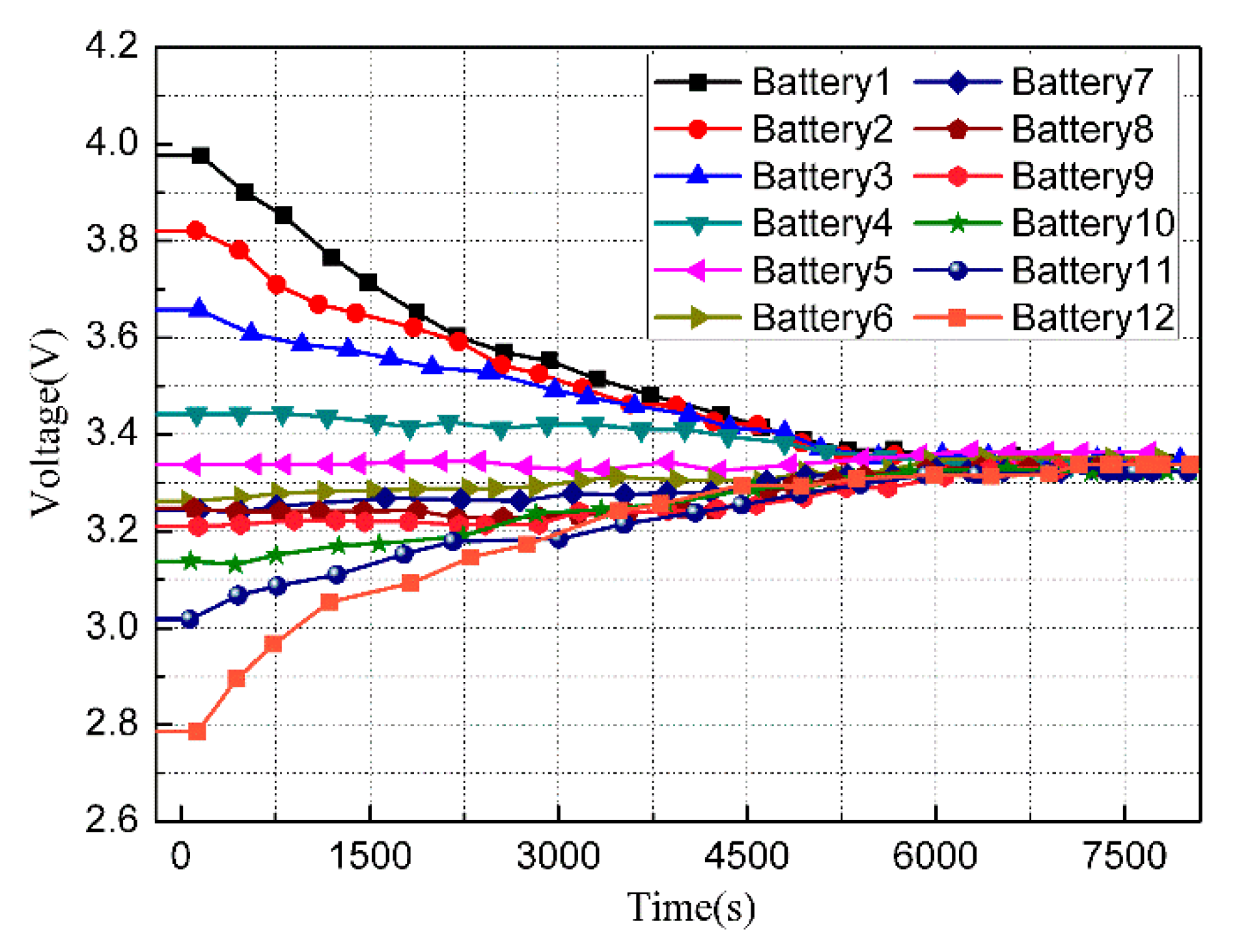
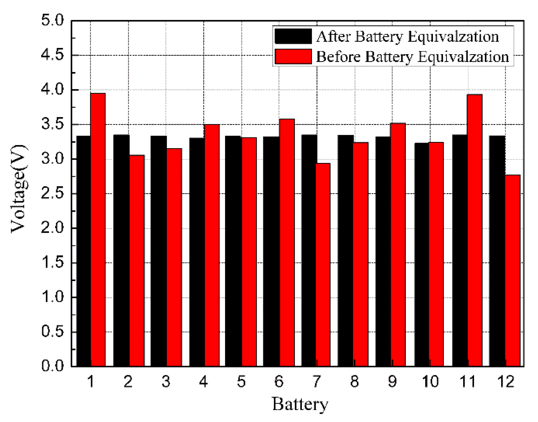
3.3. Experimental Verification

To verify the performance of the proposed voltage equalizer, a prototype was built and tested. Figure 13 shows a photograph of the experimental prototype and associated instruments. The experiment uses a “DELI PU BATTERY” 18650 Li-ion Battery with a capacity of 2800-mAh, a rated voltage of 3.7 V, a discharge cut-off voltage of 2.75 V, and an equivalent series resistance of 80 mΩ. The standard charging voltage is 0.5 C (1400 mA), the operating temperature is 0–45 °C in the state of charge, and the discharge state is −(20–60) °C. the battery pack consists of 12 batteries of 2800-mAh battery strings which can store 10.36 Ah and 124.32 Wh. When the experiment is carried out, the voltage detection frequency is 50 Hz. The switching frequency of the left and right switches is 1 Hz, the operating frequency of the bidirectional winding flyback converter is 25 kHz and the voltage difference between the beginning and the ending equalization is 30 mV.
Figure 14 shows the voltage variation of the battery cells during the overall equalization process of the battery pack. It can seem that the highest and lowest voltage of the single battery was 3.98 V and 2.78 V respectively. The entire energy transfer and conversion process can be realized by bidirectional transfer, and a gradual reduction in high voltage cells was achieved. The low voltage gradually rises and cycles in sequence until all voltages were up to the set equilibrium voltage.
Figure 15 shows a schematic diagram of voltage changes during battery pack equalization. In this mode of operation, 12 cells with large energy differences are selected for direct equalization. From the analysis of the graph, a relatively balanced state can be gradually obtained between the highest-energy battery cells and the lowest-connected battery cells, and the remaining energy was also in accordance with this equalization mode.
Figure 16 shows the voltage distribution before and after the battery voltage equalization. The horizontal axis represents different monomers and the vertical axis denotes the cell voltage. It can be noted clearly that the voltage of each cell in the battery pack is unbalanced. The voltages tend to be consistent upon equalization, which indicates that the new voltage equalization structure can effectively realize the function of voltage equalization.

4. Discussion

A comparative study of the proposed equalization method is shown in Table 2. Through comparing and analyzing the new equalizer with other equalization networks, the proposed equalizer has relative advantages in size, cost and equalization rate. The output structure of double windings is utilized to realize efficient operation in two working modes of forward and reverse excitation. It is suitable for a large-scale battery
A pack-to-cell equalization mode was formed, which has great potential in promotion and application [14]. With the coaxial winding structure, the equalization function can be realized without additional control in the whole process, but the disadvantage is that it is difficult to accurately adjust the voltage of the battery pack in actual work. The parasitic inductance and mutual inductance of the circuit cannot be accurately controlled, which influenced the operation of the circuit. This leads to the difficult consistency of battery packs for the battery management system (BMS). Additionally, this structure is not suitable for a large number of battery cells. It is challenging to wind too many windings on the same core. Finally, the true energy balance of the battery pack made it difficult to achieve balance from the battery pack to the single unit [15]. It cannot directly reduce the monomer with the highest energy and directly supplement the monomer with the lowest energy. Energy can only be transferred from the whole battery pack.
Energy can only be transferred in the whole battery pack one by one during the equalization process. However, the equalization speed is relatively slow for most batteries connected in series. A point-to-point balanced supplement can be realized by the proposed point-to-point balanced structure, but the number of switch groups is huge. If a small pressure difference has existed between the two equalization monomers in the equalization process, the equalization time is not dominant. The equalizer is based on the equalization of coaxial windings. At the same time, the advantages of a high-frequency switch of the forward converter and the small volume of flyback converter were retained. The number of switches was relatively small and the control method was flexible. In addition, in order to prevent the surge impact of high voltage and high current on the cells during the charging and discharging process of the pack, a Zener diode with an anti-parallel protection function on every single cell was applied in the new equalization structure, and the battery pack module was also equipped with fuses to ensure the safe operation of the battery pack. the proposed equalizer exhibited higher stability and better equalization by this method.

5. Conclusions

In order to solve the problem of inconsistency between the single cell in the actual use process of the power lithium-ion battery pack, this paper displays a new type of voltage equalization circuit. Comparing with the traditional equilibrium structure, the balanced mode adopted was divided into two working modes. The control method is flexible and the volume occupied by the space volume is relatively small. The balanced structure of the two windings could allow the fast equalization of two battery cells simultaneously. Meanwhile, the designed switch array circuit has a simple control mode with low energy loss. In this paper, the working principle and equalization control strategy of the voltage equalization circuit was introduced in detail and analyzed. A voltage equalization system for 12 batteries of 2800-mAh battery strings was designed in a targeted manner and a voltage equalization experiment was performed. The results show that voltage equalization of series battery packs can be realized efficiently and quickly by the proposed equalizer. The circuit became simple and efficient using a flexible control mode. It is beneficial to improve the overall performance of the battery pack, meanwhile guaranteeing the healthy operation of the battery pack.

Author Contributions

F.S. designed the study, D.S. designed the experiments and wrote the manuscript. All authors have read and approved the manuscript.

Funding

Research funded by National Natural Science Foundation of China (57807138).

Acknowledgments

Thank you for the experimental instrument support and financial support provided by the Engineering Training Center of Tianjin University of Technology.

Conflicts of Interest

This article has no conflict of interest.

References

  1. Preindl, M.A. Battery Balancing Auxiliary Power Module with Predictive Control for Electrified Transportation. IEEE Trans. Ind. Electron. 2018, 65, 6552–6559. [Google Scholar] [CrossRef]
  2. Kouchachvili, L.; Yaïci, W.; Entchev, E. Hybrid battery/supercapacitor energy storage system for the electric vehicles. J. Power Sources 2018, 374, 237–248. [Google Scholar] [CrossRef]
  3. Cao, X.; Zhong, Q.C.; Qiao, Y.C.; Deng, Z.Q. Multi-layer Modular Balancing Strategy for Individual Cells in a Battery Pack. IEEE Trans. Energy Convers. 2018, 33, 526–536. [Google Scholar] [CrossRef]
  4. Gallardo-Lozano, J.; Romero-Cadaval, E.; Milanes-Montero, M.I.; Guerrero-Martinez, M.A. Battery equalization active methods. J. Power Sources 2014, 246, 934–949. [Google Scholar] [CrossRef]
  5. Lee, K.M.; Lee, S.W.; Choi, Y.G.; Kang, B. Active Balancing of Li-Ion Battery Cells Using Transformer as Energy Carrier. IEEE Trans. Ind. Electron. 2017, 64, 1251–1257. [Google Scholar] [CrossRef]
  6. Lee, K.M.; Chung, Y.C.; Sung, C.H.; Kang, B. Active Cell Balancing of Li-Ion Batteries using LC Series Resonant Circuit. IEEE Trans. Ind. Electron. 2015, 62, 5491–5501. [Google Scholar] [CrossRef]
  7. Kutkut, N.H.; Divan, D.M. Dynamic equalization techniques for series battery stacks. In Proceedings of the Intelec’96—International Telecommunications Energy Conference, Boston, MA, USA, 6–10 October 1996; pp. 514–521. [Google Scholar]
  8. Lindemark, B. Individual cell voltage equalizers (ICE) for reliable battery performance. In Proceedings of the Thirteenth International Telecommunications Energy Conference—INTELEC 91, Kyoto, Japan, 5–8 November 1991; pp. 196–201. [Google Scholar]
  9. Park, S.-H.; Kim, T.-S.; Park, J.-S.; Moon, G.-W.; Youn, M.-J. A new battery equalizer based on buck-boost topology. In Proceedings of the 7th International Conference on Power Electronics, Daegu, Korea, 22–26 October 2007; pp. 962–965. [Google Scholar]
  10. Elserougi, A.; Massoud, A.; Ahmed, S. A Unipolar/Bipolar High-Voltage Pulse Generator Based on Positive and Negative Buck-Boost DC-DC Converters Operating in Discontinuous Conduction Mode. IEEE Trans. Ind. Electron. 2017, 64, 5368–5379. [Google Scholar] [CrossRef]
  11. Li, S.; Mi, C.C.; Zhang, M. A High-Efficiency Active Battery-Balancing Circuit Using Multiwinding Transformer. IEEE Trans. Ind. Appl. 2013, 49, 198–207. [Google Scholar] [CrossRef]
  12. Shang, Y.; Zhang, C.; Cui, N.; Guerrero, J.M. A Cell-to-Cell Battery Equalizer with Zero-Current Switching and Zero-Voltage Gap Based on Quasi-Resonant LC Converter and Boost Converter. IEEE Trans. Power Electron. 2015, 30, 3731–3747. [Google Scholar] [CrossRef]
  13. Li, Y.; Han, Y. A Module-Integrated Distributed Battery Energy Storage and Management System. IEEE Trans. Power Electron. 2016, 31, 8260–8270. [Google Scholar] [CrossRef]
  14. Xiong, H.; Fu, Y.; Dong, K. A novel point to point energy transmission voltage equalizer for Series-Connected Supercapacitors. IEEE Trans. Veh. Technol. 2016, 65, 4669–4675. [Google Scholar] [CrossRef]
  15. Karnjanapiboon, C.; Jirasereeamornkul, K.; Monyakul, V. High efficiency battery management system for serially connected battery string. In Proceedings of the IEEE International Symposium on Industrial Electronics, Seoul, Korea, 5–8 July 2009; pp. 1504–1509. [Google Scholar]
  16. Kutkut, N.H.; Wiegman, H.L.N.; Divan, D.M.; Novotny, D.W. Design considerations for charge equalization of an electric vehicle battery system. IEEE Trans. Ind. Appl. 1999, 35, 28–35. [Google Scholar] [CrossRef]
  17. Imtiaz, A.M.; Khan, F.H.; Kamath, H. A Low-Cost Time Shared Cell Balancing Technique for Future Lithium-Ion Battery Storage System Featuring Regenerative Energy Distribution. In Proceedings of the Twenty-Sixth Annual IEEE Applied Power Electronics Conference and Exposition (APEC), Fort Worth, TX, USA, 6–11 March 2011; pp. 792–799. [Google Scholar]
  18. Lim, C.S.; Lee, K.J.; Ku, N.J.; Hyun, D.S.; Kim, R.Y. A Modularized Equalization Method Based on Magnetizing Energy for a Series-Connected Lithium-Ion Battery String. IEEE Trans. Power Electron. 2014, 29, 1791–1799. [Google Scholar] [CrossRef]
Figure 1. Battery balance diagram.
Electronics 08 01426 g001
Figure 2. Battery balance-type diagram.
Electronics 08 01426 g002
Figure 3. Coaxial multi-winding equalizer.
Electronics 08 01426 g003
Figure 4. New voltage equalizer.
Electronics 08 01426 g004
Figure 5. Equalization equivalent circuit.
Electronics 08 01426 g005
Figure 6. Flyback transition timing diagram. (a) Flyback converter energy forward flow timing diagram; (b) Flyback converter energy reverse flow timing diagram.
Electronics 08 01426 g006
Figure 7. Forward transition timing diagram.
Electronics 08 01426 g007
Figure 8. RCD absorption circuit.
Electronics 08 01426 g008
Figure 9. Equalization strategy flow chart.
Electronics 08 01426 g009
Figure 10. Voltage equalization system.
Electronics 08 01426 g010
Figure 11. Switching network diagram.
Electronics 08 01426 g011
Figure 12. Flyback switch drive circuit.
Electronics 08 01426 g012
Figure 13. (a) Voltage acquisition circuit; (b) experimental prototype and associated instruments.
Electronics 08 01426 g013
Figure 14. Voltage curve during forward go equalization.
Electronics 08 01426 g014
Figure 15. Voltage curve during equalization process.
Electronics 08 01426 g015
Figure 16. Voltage distributions of the battery pack.
Electronics 08 01426 g016
Table 1. Main component parameters of equalizing circuit system.
ParameterValue
Primary DC–DC ConverterMosfect SwitchIPB200N
Rectifier DiodeIN5822
Transfor-merCoreEP20
N1:N2:N333:3:3
Lm367 uH
Primary RCDR38 kΩ
C21 nF
Secondary DC–DC converterMosfect SwitchAUIRF3504
Rectifier diodeSR560
Secondary RCDR803 Ω
C1 uF
Selection SwitichP-MOSAOD409
N-MOSAUIRF3504
OptocuplerPC817
Table 2. Parameters the prototype.
Balanced ModeEnergy Dissipation TypeNon-Energy Dissipation Type
Cell to CellPack to VellCell to PackCell to Pack to Cell
TypeFixed Resistor [7]Shut Resister [8]Single Layer [9]Buck-Boost [12]Multi-Stage Winding [14] Trans-FormerSingle Winding [15] Trans-FormerMany-to-One [16]Two Way [17]Inter Group [18]#New Proposed Topology
Inductance001N00N02n + 40
Capacitance0012N110003
Transformer000021N221
Switch0N2N + 4N42NN2NN2N
Diode0000N + 11N100
VolumeEEEEPGPPPG
Control methodEEPSPPEGGE
speedPGGGGGEGGE
costEEEEPPPPPG
E: excellent, G: good, S: satisfactory, P: poor.

