Article

A Method to Identify Lithium Battery Parameters and Estimate SOC Based on Different Temperatures and Driving Conditions

Department of Automotive Engineering, School of Mechanical Engineering, Guizhou University, Guiyang 550025, China
*
Author to whom correspondence should be addressed.
Electronics 2019, 8(12), 1391; https://doi.org/10.3390/electronics8121391
Submission received: 2 November 2019 / Revised: 16 November 2019 / Accepted: 18 November 2019 / Published: 22 November 2019

Abstract

:
State of charge (SOC) plays a significant role in the battery management system (BMS), since it can contribute to the establishment of energy management for electric vehicles. Unfortunately, SOC cannot be measured directly. Various single Kalman filters, however, are capable of estimating SOC. Under different working conditions, the SOC estimation error will increase because the battery parameters cannot be estimated in real time. In order to obtain a more accurate and applicable SOC estimation than that of a single Kalman filter under different driving conditions and temperatures, a second-order resistor capacitor (RC) equivalent circuit model (ECM) of a battery was established in this paper. Thereafter, a dual filter, i.e., an unscented Kalman filter–extended Kalman filter (UKF–EKF) was developed. With the EKF updating battery parameters and the UKF estimating the SOC, UKF–EKF has the ability to identify parameters and predict the SOC of the battery simultaneously. The dual filter was verified under two different driving conditions and three different temperatures, and the results showed that the dual filter has an improvement on SOC estimation.

1. Introduction

With the increasing energy crisis, alternative energy vehicles have been given full attention. Lithium-ion batteries (LIBs) have become the power source of electric vehicles (EVs) because of their high energy density and long service life [1]. Battery management systems (BMS) can predict the driving mileage of EVs through the state of charge (SOC) of LIBs, and they can formulate the energy management strategies of EVs, which can not only extend the life of batteries, but the driving mileage of cars, as well. The monitoring of SOC also plays a significant role in preventing batteries in EVs from some dangerous operations, like overcharging or overdischarging.
Unfortunately, unlike other parameters of the battery, such as current and terminal voltage, SOC cannot be measured directly. Many scholars have studied SOC estimation for a long time; below are some common methods of SOC estimation:
(i) Although the Coulomb counting method (CCM) is uncomplicated and has been applied in SOC prediction, in practice, error accumulation will gradually increase due to the influence of uncertain noise. In addition, the initial value of the SOC will also affect the estimation accuracy, so it is not appropriate for the SOC estimation of LIBs in EVs.
(ii) Through the open-circuit voltage method (OCVM), a relatively functional relationship between the open-circuit voltage (OCV) and the SOC can be found; hence, SOC can be estimated according to the changing OCV at work. It is, however, limited to estimating the SOC in LIBs for the need of long rest and the neglect of changes in the internal resistance of LIBs during working.
(iii) The improvements in computer computing ability are helpful in the popularization and application of machine learning (ML). Some ML algorithms, such as neural networks (NN) [2,3], extreme learning machines (EXL) [4,5], and support vector machines (SVM) [6], only need to train some input parameters, such as terminal voltage, operating current, resistance, and the temperatures of LIBs during working, to predict SOC. However, because of the constraints of sample training and the large amounts of computation required, it is difficult to meet the requirements of BMS to predict SOC at this time.
(iv) Based on an electrical equivalent circuit model (ECCM), some advanced Kalman filter (KF) methods, like the extended Kalman filter (EKF) [7,8], the unscented Kalman filter (UKF), [9] and the cubature Kalman filter (CKF), [10] have demonstrated their abilities to accurately predict SOC. Moreover, in order to deal with the uncertainties of system noise in SOC estimation, some Kalman filters improved by adaptive algorithms, such as the adaptive extended Kalman filter (AEKF) [11], the adaptive unscented Kalman filter (AUKF), [12] and the adaptive cubature Kalman filter (ACKF) [13], have been used to improve the estimation accuracy of SOC. Nevertheless, the resistances of lithium batteries vary in different working conditions and temperatures, which are neglected when the SOC is estimated by a single Kalman filter. As a consequence, the estimation error of SOC will increase. It is a common approach to identify battery parameters by the hybrid pulse power characteristic (HPPC) offline test, but the accuracy of this method is not guaranteed, and it does consume a lot of time.
In order to resolve the aforementioned shortcomings of the single Kalman filter, many scholars have proposed joint estimation methods to simultaneously achieve SOC estimation and battery parameter identification online. Xiong et al. [14] proposed a joint estimator to predict SOC and state of power (SOP) capabilities, with recursive least squares (RLS) successfully updating battery parameters and the AEKF achieving the estimation of the SOC and power capacity. Wei et al. [15] compared three methods—the dual extended Kalman filter (DEKF), the recursive least squares–extended Kalman filter (RLS–EKF), and the noise compensating EKF (NC-EKF)—for battery parameter identification and SOC online estimation. All of them had high accuracy for SOC estimation and parameter identification under low noise interference, but as the unknown interference increased, they showed their own weaknesses in calculating cost, number of parameters to be adjusted, and robustness of estimation. These SOC estimators are only based on the first-order RC ECM, and RLS is not suitable for estimating nonlinear systems. EKF also suffers from low SOC estimation accuracy for abandoning higher order. The establishment of UKF–EKF by Zhang et al. [1] has a good ability to predict the SOC and the parameters of the battery pack, but its stability has not been verified at different temperatures.
In fact, in addition to the unknown noise at work, the estimation of the SOC and identification of the parameters of the battery are usually influenced by ambient temperature, which is reflected in the changes of the OCV–SOC function relationship and the battery’s internal resistance. In order to realize SOC estimation and online parameter identification of the battery simultaneously, this paper proposes a second-order RC ECM of the battery, and a joint estimation model, i.e., the UKF–EKF is structured. The UKF is used to predict the SOC, which solves the shortcomings of insufficient accuracy of the EKF’s SOC estimation, while the EKF updates the battery parameters, which further enhances the accuracy of the SOC estimation.

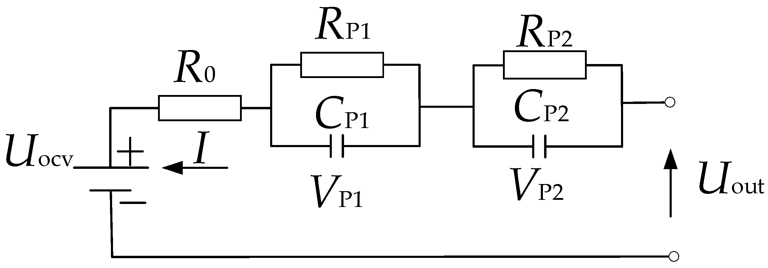
2. Battery of the Equivalent Circuit Model

The successful application of the Kalman filter in SOC estimation depends on the accurate model of the battery. Many studies [16,17,18] have shown that the ECM can be successfully used in SOC estimation because it can accurately reflect the physical and chemical changes of the battery, and the computing cost is low, which conforms to the requirements of a BMS. Considering the accuracy and computational complexity of the battery model, a second-order ECM is selected and plotted in Figure 1.
I is the working current, which is positive when discharging and negative when charging. R0 represents ohmic resistance. RP1 and CP1 are resistance and capacitance of electrochemical polarization, respectively, while RP2 and CP2 represent the resistance and capacitance of concentration polarization, respectively. Uocv and Uout are open-circuit voltage and terminal voltage, respectively. VP1 and VP2 are polarization voltage, and the state equation of the battery can be expressed by Equation (1):
{ V P 1 = 1 R P 1 C P 1 V P 1 + 1 C P 1 I V P 2 = 1 R P 2 C P 2 V P 2 + 1 C P 2 I U o u t = U o c v V P 1 V P 2 I R 0 .

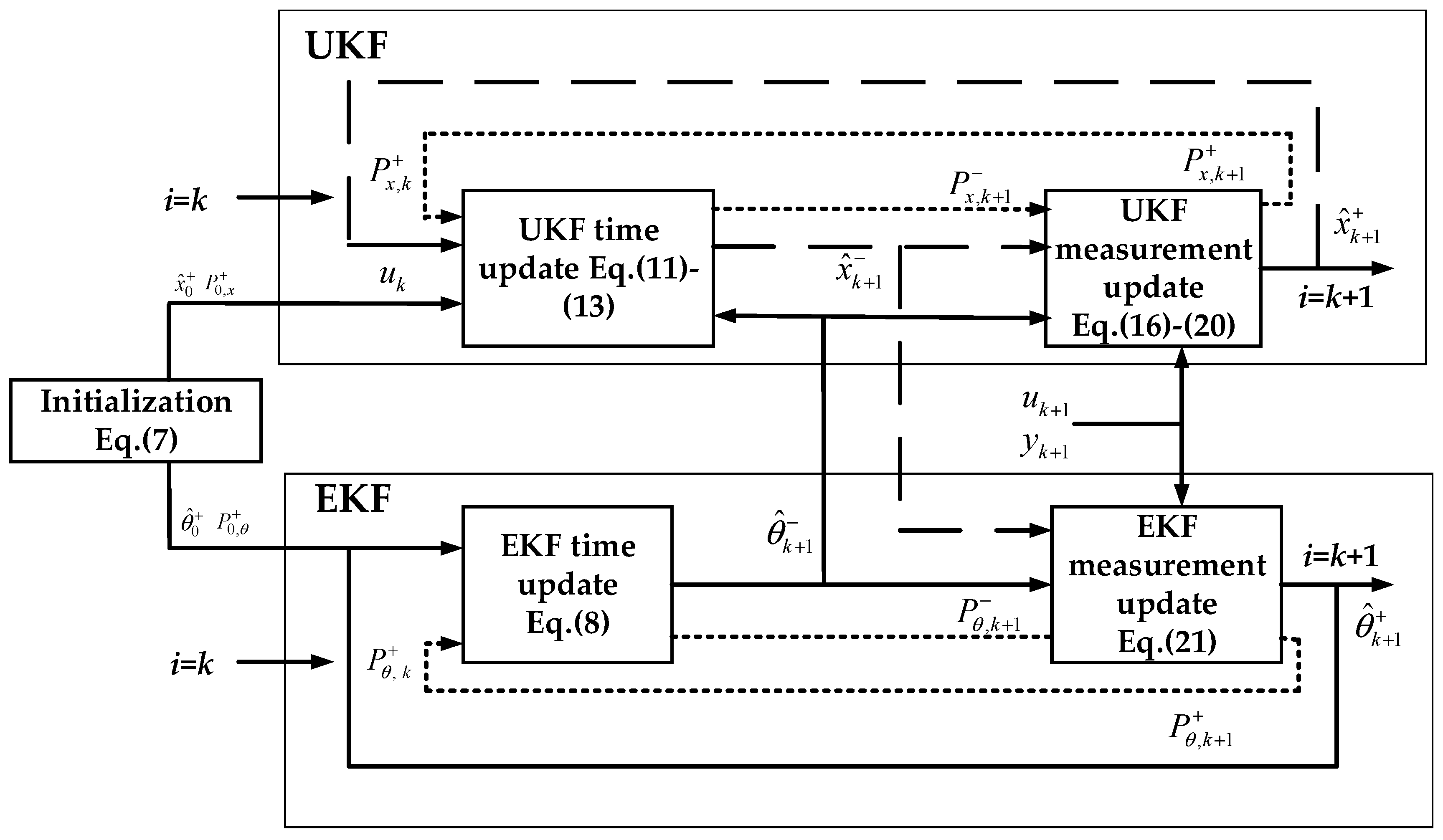
3. Dual Kalman Filter Design

In order to overcome the disadvantages of the traditional single unscented Kalman filter, which regards internal resistance as a constant, it is an advisable method to apply the dual Kalman filter in the joint online estimation of battery parameters and SOC. The UKF–EKF consists of two running parallel KFs, i.e., EKF is employed in the identification of battery parameters, while UKF is applied to SOC estimation.
The SOC can be expressed by the following formula:
S O C = S O C 0 + Δ t i ( t ) C p ,
where SOC0 is the initial SOC, and Cp and i(t) represent the rated capacity of the batteries and current, respectively.
Combine Equations (1) and (2), and a new equation of state with battery parameters can be obtained.
{ X k + 1 = [ 1 0 0 0 e Δ t R P 1 C P 1 0 0 0 e Δ t R P 2 C P 2 ] × X k + [ Δ t / C p R P 1 ( 1 e Δ t R P 1 C P 1 ) R P 2 ( 1 e Δ t R P 2 C P 2 ) ] × I k + w k x θ k + 1 = θ k + w k θ
U o u t , k = U o c v ( S O C k ) V P 1 , k V P 2 , k I k R 0 + v k ,
where the state vector Xk= [SOCk VP1,k VP2,k]T, τ1 = RP1CP1, τP2 = RP2CP2, and τP1 and τP2 are time constants in ECM. OCV can be obtained by fitting the relationship with SOC. w k x ~N(0, Qx) and w k θ ~N(0, Qθ) are process noise for state and parameters, respectively, measurement noise is vk ~ N(0, Rx), and battery parameters are θ = [R0, RP1, CP1, RP2, CP2]T.
To obtain a nonlinear system with state and parameters, Equations (3) and (4) can be rewritten as:
x k + 1 = f ( x k , θ k , u k ) + w k x = θ k + w k θ
y k = g ( x k , θ k , u k ) + v k ,
where the control variable uk = Ik.
The detailed steps of UKF–EKF are shown below, and the flow chart is shown in Figure 2.
(1)
Initialization:
x ^ 0 + = E [ x 0 ] P 0 , x + = E [ ( x 0 x ^ 0 + ) ( x 0 x ^ 0 + ) ] T θ ^ 0 + = E [ θ ^ 0 ] P 0 , θ + = E [ ( θ 0 θ ^ 0 + ) ( θ 0 θ ^ 0 + ) ] T
(2)
Time update for battery parameters in EKF:
θ ^ k + 1 = θ ^ k + P θ , k + 1 = P θ , k + + Q θ , k
(3)
Sigma sampling point and weight calculate for UKF:
{ x k | k 0 = x ^ k | k , i = 0 x k | k i = x ^ k | k + ( ( n + λ ) P x , k + ) i , i = 1 ~ n x k | k i = x ^ k | k ( ( n + λ ) P x , k + ) i , i = n + 1 ~ 2 n
{ ω m ( 0 ) = λ n + λ ω c ( 0 ) = λ n + λ + ( 1 α 2 + β ) ω m ( i ) = ω c ( i ) = λ 2 ( n + λ ) , i = 1 ~ 2 n ,
where n is the state dimension of the battery. Λ = α2(n+k)-n, the function of α is to control the distribution of sampling points, and the parameter k usually guarantees that the variance matrix is semipositive definite. β is the non-negative weight coefficient; in this study, n = 3, α = 0.01, k = 0, β = 2.
(4)
State estimation and error covariance time update:
x k + 1 | k i = f ( x k | k i )
x ^ k + 1 | k = i = 0 2 n ω ( i ) x k + 1 | k i
P k + 1 | k = i = 0 2 n ω ( i ) [ x ^ k + 1 | k x k + 1 | k i ] [ x ^ k + 1 | k x k + 1 | k i ] T + Q x , k .
(5)
Update measurement with posteriori estimation:
Z k + 1 | k i = g ( x k + 1 | k i )
Z ^ k + 1 | k i = i = 0 2 n ω ( i ) Z ^ k + 1 | k i .
(6)
Update measurement covariance:
P y , k = i = 0 2 n ω ( i ) [ Z k + 1 | k i Z ^ k + 1 | k i ] [ Z k + 1 | k i Z ^ k + 1 | k i ] T + R x , k
P x , k = i = 0 2 n ω ( i ) [ x k + 1 | k i Z ^ k + 1 | k i ] [ Z k + 1 | k i Z ^ k + 1 | k i ] T .
(7)
Calculate UKF gain matrix:
K k + 1 = P x , k ( P y , k ) 1 .
(8)
State estimation and error covariance measurement update:
x ^ k + 1 | k + 1 = x ^ k + 1 | k + K k + 1 [ Z k + 1 i Z ^ k + 1 | k i ]
P k + 1 | k + 1 = P k + 1 | k K k + 1 P z , k ( K k + 1 ) T .
(9)
EKF measurement update for battery parameters:
K k , θ = P θ , k + 1 ( H ^ k , θ ) T ( H ^ k , θ P θ , k + 1 ( H ^ k , θ ) T + R k , θ ) 1 θ ^ k + 1 + = θ ^ k + 1 + K k , θ ( y k y ^ k ) P θ , k + 1 + = ( I K k , θ H ^ k , θ ) P θ , k + 1
The Jacobian equation of battery parameters is as follows:
H ^ k θ = d g ( x ^ k + 1 , u k + 1 , θ ) d θ | θ = θ ^ k + 1 = g ( x ^ k + 1 , u k + 1 , θ ) θ + g ( x ^ k + 1 , u k + 1 , θ ) x ^ k + 1 d x ^ k + 1 d θ
d x ^ k + 1 d θ = f ( x ^ k + , u k , θ ) θ + f ( x ^ k + , u k , θ ) x ^ k + d x ^ k + d θ
d x ^ k + d θ = d x ^ k d θ K k x d g ( x ^ k , u k , θ ) d θ ,
where
g ( x ^ k + 1 , u k + 1 , θ ) θ = [ I k + 1 , 0 , 0 , 0 , 0 ]
g ( x ^ k + 1 , u k + 1 , θ ) x ^ k + 1 = [ U o c v / S O C k + 1 , 1 , 1 ]
f ( x ^ k + , u k , θ ) θ = [ 0 0 0 0 0 0 a 2 , 2 a 2 , 3 0 0 0 0 0 a 3 , 4 a 3 , 5 ]
a 2 , 2 = V P 1 , k Δ t R P 1 2 C P 1 exp ( Δ t / τ P 1 ) I k ( exp ( Δ t / τ P 1 ) 1 ) I k Δ t R P 1 C P 1 exp ( Δ t / τ P 1 ) ,
a 2 , 3 = ( Δ t / R P 1 C P 1 2 ) ( V P 1 , k R P 1 I k ) exp ( Δ t / τ P 1 ) ,
a 3 , 4 = V P 2 , k Δ t R P 2 2 C P 2 exp ( Δ t / τ P 2 ) I k ( exp ( Δ t / τ P 2 ) 1 ) I k Δ t R P 2 C P 2 exp ( Δ t / τ P 2 ) ,
a 3 , 5 = ( Δ t / R P 2 C P 2 2 ) ( V P 2 , k R P 2 I k ) exp ( Δ t / τ P 2 ) .

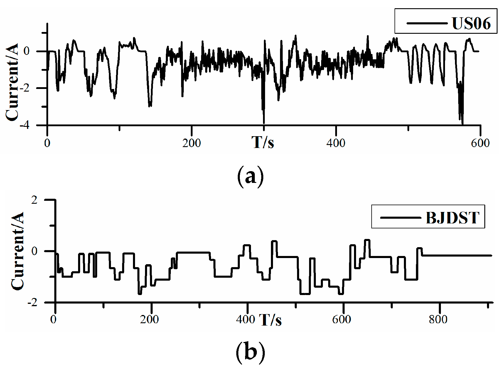
4. Experimental Design

The dataset of the 18650 battery was collected from an experiment conducted by Zheng et al. [19]. Battery data profiles consist of incremental current OCV and dynamic test profiles. The first profile data can be used to obtain the relationship between OCV and SOC, and Figure 3 plots OCV–SOC in incremental current OCV at 0, 25, and 45 °C, corresponding to low temperature, room temperature, and high temperature, respectively. It can be seen that at different temperatures, the OCV–SOC curves are different, which indicates that the electrode characteristics of the battery are influenced by temperature, which will affect the SOC estimation. The function of dynamic test profiles is to verify the ability of the UKF–EKF to achieve SOC estimation and parameter identification under different temperatures. There are two battery test loading profiles, including the highway condition, Highway Driving Schedule (US06), and the urban condition, Beijing Dynamic Stress Test (BJDST) in Figure 4. As can be seen from Figure 4, the charging/discharging current under the US06 working condition is larger; in addition, this working condition is more complex than the BJDST. The prediction results under different working conditions are shown in Section 5; the detailed parameters of the battery are shown in Table 1.

5. Results and Discussion

The estimation of SOC and the identification of battery parameters were verified under two working conditions (US06 and BJDST), at three different temperatures.

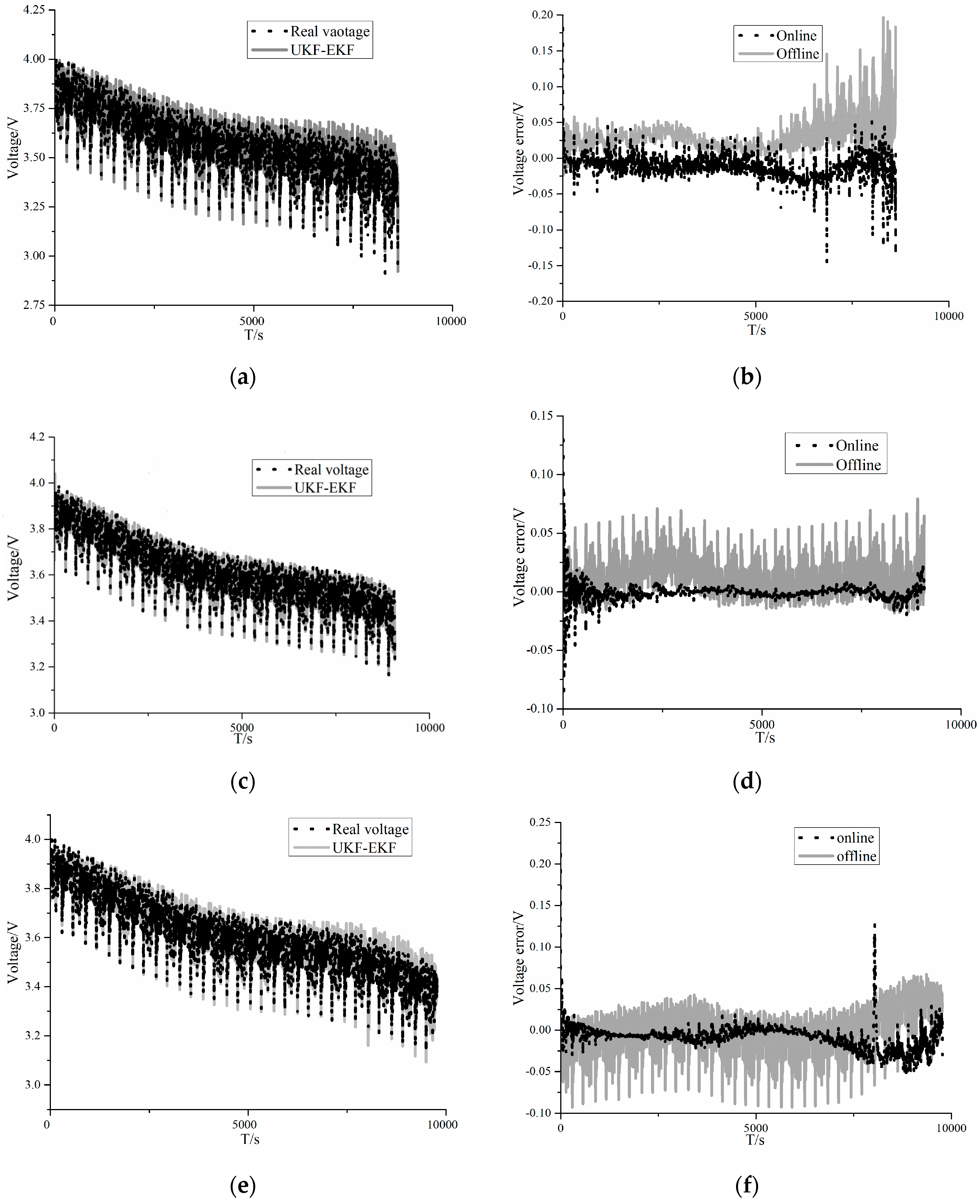
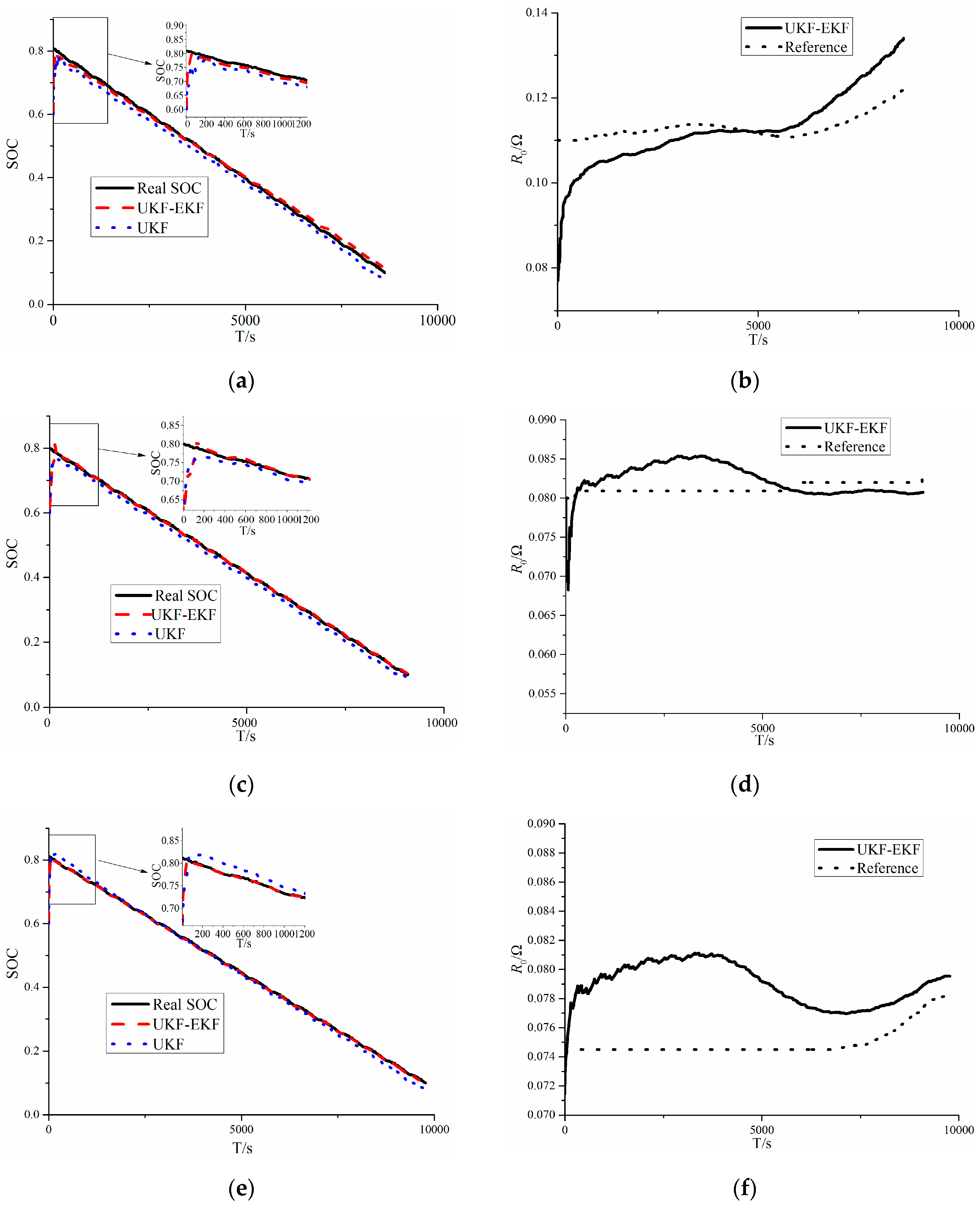
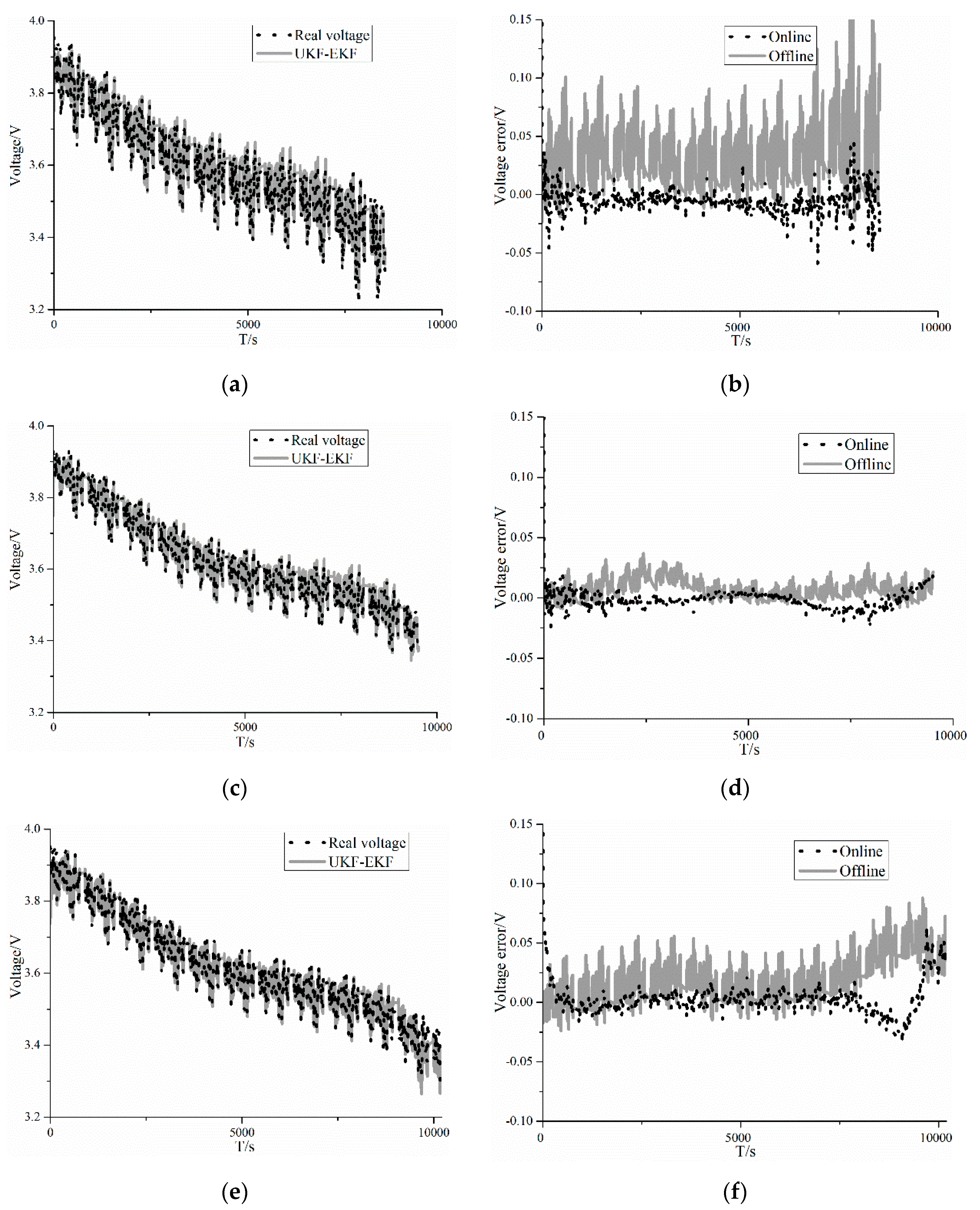
5.1. Results of US06

The results of US06 are plotted in Figure 5 and Figure 6. Figure 5a,c,e plots the voltage of the UKF–EKF and the real voltage at 0, 25, and 45 °C, respectively. Figure 5b,d,f correspondingly compares online estimated voltage errors and offline estimated voltage errors at different temperatures; the online estimation is implemented by the UKF–EKF. Figure 6a,c,e describes the results of SOC estimation between the UKF–EKF and UKF at 0, 25, and 45 °C, respectively. It should be noted that at various temperatures, the initial values of the real SOC are 0.8, but the initial values of the SOC for algorithms are 0.6. Figure 6b,d,f shows the identification of R0 at different temperatures.
It can be seen from Figure 5 and Table 2, in terms of voltage prediction, the root mean square errors (RMSEs) of voltage for online estimation and offline estimation at 0 °C are 17.6 and 34.1 mV, respectively, and they are 6.2 and 17.4 mV for online estimation and offline estimation at 25 °C, while the online and offline RMSEs are 16.9 and 23.3 mV at 45 °C, respectively.
According to Figure 6 and Table 2, for the identification of R0 at 0 °C, the RMSEs of R0 for the UKF–EKF is 12.1 mΩ, and it is 5.6 mΩ at 25 °C, while the figure for RMSE of R0 at 45 °C is 7.9 mΩ. In terms of the SOC estimation, it is clear that at 0 °C, the RMSEs of the SOC for the UKF–EKF and UKF are 1.00% and 2.12%, respectively, and at 25 °C, they are 0.76% and 1.72% for the UKF–EKF and UKF, respectively, while the figures for RMSEs of SOC for the UKF–EKF and UKF are 0.51% and 1.31% at 45 °C, respectively.
The results show that the UKF–EKF, which can identify battery parameters online, has a better performance than the UKF in SOC estimation at different temperatures; in addition, the voltage errors of online estimation are smaller. It is clear that at 0 °C, the differences between estimations of the SOC and voltage become greater. Moreover, at 25 and 45 °C, the UKF–EKF has greater accuracy in estimating R0 than at 0 °C.

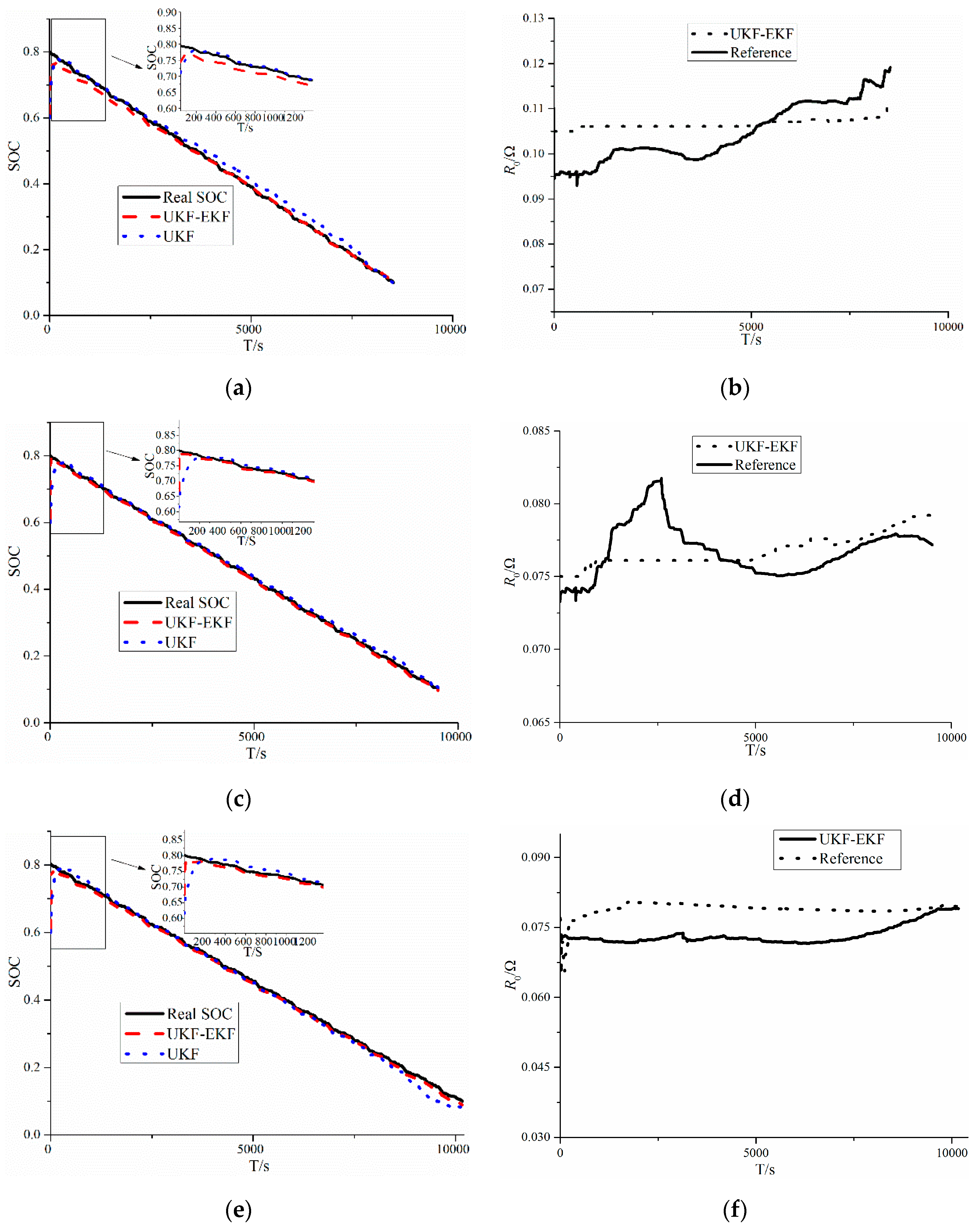
5.2. Results of BJDST

The results of BJDST are plotted in Figure 7 and Figure 8. Figure 7a,c,e plots the voltage of the UKF–EKF and the real voltage at 0, 25, and 45 °C, respectively. Figure 7b,d,f correspondingly compares online estimated voltage errors and offline estimated voltage errors at different temperatures; the online estimation is implemented by the UKF–EKF. Figure 8a,c,e describes the results of the SOC estimation between the UKF–EKF and UKF at 0, 25, and 45 °C, respectively. It should be noted that at various temperatures, the initial values of the real SOC are 0.8, but the initial values of the SOC for the algorithms are 0.6. Figure 8b,d,f shows the identification of R0 at different temperatures.
It can be seen from Figure 7 and Table 3, in terms of voltage prediction, the root mean square errors (RMSEs) of voltage for online estimation and offline estimation at 0 °C are 10.7 and 17.4 mV, respectively, and 5.8 and 9.1 mV for online estimation and offline estimation at 25 °C, while the online and offline RMSEs are 10.1 and 24.7 mV at 45 °C, respectively.
According to Figure 8 and Table 3, for the identification of R0 at 0 °C, the RMSE of R0 for the UKF–EKF is 7.3 mΩ, and it is 3.3 mΩ at 25 °C, while the figure for RMSE of R0 at 45 °C is 6.1 mΩ. In terms of SOC estimation, it is clear that at 0 °C, the RMSEs of SOC for the UKF–EKF and UKF are 0.97% and 1.95%, respectively, and at 25 °C, they are 0.61% and 1.31% for the UKF–EKF and UKF, respectively, while the figures for RMSEs of SOC for the UKF–EKF and UKF are 0.82% and 1.75% at 45 °C, respectively.
The results showed that the UKF—EKF, which can identify battery parameters online, has a better performance than the UKF in SOC estimation at different temperatures, in addition to the voltage errors of online estimation being smaller. It is clear that at 0 °C, the differences in estimation of SOC and voltage become greater. Moreover, at 25 and 45 °C, the UKF–EKF has greater accuracy in estimating R0 than at 0 °C.
In summary, the UKF–EKF established in this study has an accurate and reliable ability to estimate the SOC and identify parameters of the battery at different temperatures and working conditions. As can be seen in Table 2 and Table 3, the errors of the SOC estimated by the UKF–EKF are within 1.00%, and the estimated errors of internal resistance are within 15 mΩ. In addition, with the ability to predict internal resistance in real time, the UKF–EKF can provide a better estimation of voltage, with the estimated errors of voltage within 20 mV. It is noted that at the same temperature, the predictions of the SOC, the parameters, and the voltage by the UKF–EKF in the BJDST are better than those in the US06, mainly because the load current under the US06 condition is more complex than that under the BJDST condition. Hence, the RMSEs of the SOC and voltage in the BJDST condition are smaller than the figures for the US06 condition. In addition, the more complex working conditions influence the estimations of internal resistance; thus, the identification of R0 in the BJDST condition shows better results. According to the results, battery parameters are temperature-sensitive, because under the same working condition, the predictions of the SOC, voltage, and internal resistance are better at 25 and 45 °C. One of the reasons for this is that at low temperatures (0 °C), the battery model is not accurate enough, which can be reflected in the dynamic hysteresis of OCV in the OCV–SOC curves. At 25 °C, better results of voltage prediction are obtained with smaller errors of parameter estimation than those at 45 °C, which indicates that the accuracy of the battery model at high temperatures (45 °C) is lower than that at room temperature (25 °C). Therefore, compared with other temperatures, the battery model at room temperature is the least different from the real battery, which results in a better SOC estimation at room temperature. Although battery parameters change at different temperatures and in different working conditions, which affects the accuracy of the battery model, the UKF–EKF, with the ability to update battery parameters in real time, reduces external influences through self-correction, and obtains satisfactory SOC estimations.

6. Conclusions

SOC estimation is an important factor for BMS in EVs, as it can provide a basis for the energy management of EVs. In order to obtain an accurate SOC estimation under various conditions, a dual filter to estimate SOC was established.
(1) SOC estimation is greatly influenced by temperature and working conditions, which can be reflected by the differences in the OCV–SOC curves at different temperatures and the prediction results of the two working conditions.
(2) The second-order ECM proposed in this study shows its great performance, since it can accurately reflect the dynamic changes of batteries and the voltage errors of online and offline estimations are within 35 mV.
(3) The UKF–EKF, with its ability to identify battery parameters online, is an improvement on the UKF for SOC estimation, which can be verified in different working conditions (US06 and BJDST) and at different temperatures (0, 25, and 45 °C). Future work will be to verify the feasibility of SOC estimations of other types of batteries and their feasibility at a wider temperature range.

Author Contributions

Conceptualization, F.H. and Y.Z.; Methodology, Y.Z.; Software, Y.Z.; Validation, W.W., Y.Z.; Formal Analysis, Y.Z.; Resources, W.W.; Data Curation, W.W.; Writing-Original Draft Preparation, Y.Z.; Writing-Review & Editing, F.H.; Supervision, F.H.

Funding

This work was funded by the Guizhou Province Science and Technology Support Program, grant number [2019]2155.

Conflicts of Interest

The authors declare no conflict of interest.

References

  1. Zhang, X.; Wang, Y.; Yang, D.; Chen, Z.H. An on-line estimation of battery pack parameters and state-of-charge using dual filters based on pack model. Energy 2016, 115, 219–229. [Google Scholar] [CrossRef]
  2. Ephrem, C.; Kollmeyer, P.J.; Matthias, P.; Emadi, A. State-of-charge estimation of Li-ion batteries using deep neural networks: A machine learning approach. J. Power Sources 2018, 400, 242–255. [Google Scholar]
  3. He, W.; Williard, N.; Chen, C.; Pecht, M. State of charge estimation for Li-ion batteries using neural network modeling and unscented Kalman filter-based error cancellation. Int. J. Elec. Power Energy Syst. 2014, 62, 783–791. [Google Scholar] [CrossRef]
  4. Du, J.; Liu, Z.; Wang, Y. State of charge estimation for Li-ion battery based on model from extreme learning machine. Control Eng. Pract. 2014, 26, 11–19. [Google Scholar] [CrossRef]
  5. Cao, W.P.; Ming, Z.; Wang, X.Z.; Cai, S.B. Improved bidirectional extreme learning machine based on enhanced random searsch. Memet. Comput. 2017, 11, 19–26. [Google Scholar] [CrossRef]
  6. Hu, J.N.; Hu, J.J.; Lin, H.B.; Li, X.P.; Jiang, C.L.; Qiu, X.H.; Li, W.S. State-of-charge estimation for battery management system using optimized support vector machine for regression. J. Power Sources 2014, 269, 682–693. [Google Scholar] [CrossRef]
  7. Xiong, B.Y.; Zhao, J.Y.; Wei, Z.B.; Skyllas-Kazacos, M. Extended Kalman filter method for state of charge estimation of vanadium redox flow battery using thermal-dependent electrical model. J. Power Sources 2014, 262, 50–61. [Google Scholar] [CrossRef]
  8. He, H.G.; Xiong, R.; Fan, J.X. Evaluation of Lithium-Ion Battery Equivalent Circuit Models for State of Charge Estimation by an Experimental Approach. Energies 2011, 4, 582–598. [Google Scholar] [CrossRef]
  9. He, J.G.; Chen, D.; Pan, C.F.; Chen, L.; Wang, S.H. State of charge estimation of power Li-ion batteries using a hybrid estimation algorithm based on UKF. Electrochim. Acta 2016, 21, 101–109. [Google Scholar]
  10. Peng, J.K.; Luo, J.Y.; He, H.W.; Lu, B. An improved state of charge estimation method based on cubature Kalman filter for lithium-ion batteries. Appl. Energy 2019, 253, 113520. [Google Scholar] [CrossRef]
  11. Xiong, R.; Gong, X.Z.; Mi, C.C.; Sun, F.C. A robust state-of-charge estimator for multiple types of lithium-ion batteries using adaptive extended Kalman filter. J. Power Sources 2013, 243, 805–816. [Google Scholar] [CrossRef]
  12. Peng, S.M.; Chen, C.; Shi, H.B.; Yao, Z.L. State of Charge Estimation of Battery Energy Storage Systems Based on Adaptive Unscented Kalman Filter with a Noise Statistics Estimator. IEEE Access 2017, 5, 13202–13212. [Google Scholar] [CrossRef]
  13. Xia, B.Z.; Wang, H.Q.; Yong, T.; Wang, M.W. State of Charge Estimation of Lithium-Ion Batteries Using an Adaptive Cubature Kalman Filter. Energies 2015, 8, 5916–5936. [Google Scholar] [CrossRef]
  14. Xiong, R.; Sun, F.C.; He, H.W.; Nguyen, T.D. A data-driven adaptive state of charge and power capability joint estimator of lithium-ion polymer battery used in electric vehicles. Energy 2013, 63, 295–308. [Google Scholar] [CrossRef]
  15. Wei, Z.B.; Zhao, J.Y.; Zou, C.F.; Lim, T.M.; Tseng, K.J. Comparative study of methods for integrated model identification and state of charge estimation of lithium-ion battery. J. Power Sources 2018, 402, 189–197. [Google Scholar] [CrossRef]
  16. Shen, P.; Ouyang, M.; Lu, L.; Li, J.; Feng, X. The co-estimation of state of charge, state of health, and state of function for lithium-ion batteries in electric vehicles. IEEE. Trans. Veh. Technol. 2018, 67, 92–103. [Google Scholar] [CrossRef]
  17. Sepasi, S.; Ghorbani, R.; Liaw, B.Y. Improved extended Kalman filter for state of charge estimation of battery pack. J. Power Sources 2014, 255, 368–376. [Google Scholar] [CrossRef]
  18. Shrivastava, P.; Soon, T.K.; Idris, M.Y.I.B.; Mekhilef, S. Overview of model-based online state-of-charge estimation using Kalman filter family for lithium-ion batteries. Renew. Sust. Energy Rev. 2019, 113, 109–233. [Google Scholar] [CrossRef]
  19. Zheng, F.D.; Xing, Y.J.; Jiang, J.C.; Sun, B.X.; Kim, J.H. Influence of different open circuit voltage tests on state of charge online estimation for lithium-ion batteries. Appl. Energy 2016, 183, 513–525. [Google Scholar] [CrossRef]
Figure 1. Second-order resistor capacitor (RC) equivalent circuit model (ECM) of a battery.
Electronics 08 01391 g001
Figure 2. Flow chart of the unscented Kalman filter–extended Kalman filter (UKF–EKF).
Electronics 08 01391 g002
Figure 3. The relation diagram of open-circuit voltage (OCV)–state of charge (SOC) at different temperatures.
Electronics 08 01391 g003
Figure 4. Profiles of battery test loading: (a) Highway Driving Schedule (US06); (b) Beijing Dynamic Stress Test (BJDST).
Electronics 08 01391 g004
Figure 5. Results of voltage comparison in US06: (a) comparison between the UKF–EKF model voltage and real voltage at 0 °C; (b) comparison of voltage errors between online and offline estimations at 0 °C; (c) comparison between the UKF–EKF model voltage and real voltage at 25 °C; (d) comparison of voltage errors between online and offline estimations at 25 °C; (e) comparison between the UKF–EKF model voltage and real voltage at 45 °C; (f) comparison of voltage errors between online and offline estimations at 45 °C.
Electronics 08 01391 g005
Figure 6. Results of the estimation of the SOC and ohmic resistance (R0) in US06: (a) SOC comparison between the UKF–EKF and UKF at 0 °C; (b) R0 identification of the UKF–EKF at 0 °C; (c) SOC comparison between the UKF–EKF and UKF at 25 °C; (d) R0 identification of the UKF–EKF at 25 °C; (e) SOC comparison between the UKF–EKF and UKF at 45 °C; (f) R0 identification of the UKF–EKF at 45 °C.
Electronics 08 01391 g006
Figure 7. Results of voltage comparisons in BJDST: (a) comparison between the UKF–EKF model voltage and real voltage at 0 °C; (b) comparison of voltage errors between online and offline estimations at 0 °C; (c) comparison between the UKF–EKF model voltage and real voltage at 25 °C; (d) comparison of voltage errors between online and offline estimations at 25 °C; (e) comparison between the UKF–EKF model voltage and real voltage at 45 °C; (f) comparison of voltage errors between online and offline estimations at 45 °C.
Electronics 08 01391 g007
Figure 8. Results of estimation of the SOC and R0 in BJDST: (a) SOC comparison between the UKF–EKF and UKF at 0 °C; (b) R0 identification of the UKF–EKF at 0 °C; (c) SOC comparison between the UKF–EKF and UKF at 25 °C; (d) R0 identification of the UKF–EKF at 25 °C; (e) SOC comparison between the UKF–EKF and UKF at 45 °C; (f) R0 identification of the UKF–EKF at 45 °C.
Electronics 08 01391 g008
Table 1. Battery parameters.
Type18650
Normal Voltage3.6 V
Normal Capacity2 Ah
Upper/lower cut-off voltage4.2 V/2.5 V
operating temperature0–55 °C
Table 2. The estimation of root mean square errors (RMSEs) for the UKF–EKF and UKF under US06.
Temperatures0 °C25 °C45 °C
UKF–EKFUKFUKF–EKFUKFUKF–EKFUKF
SOC (%)1.002.120.761.720.511.31
Voltage (mV)17.634.16.217.416.923.3
R0 (mΩ)12.1-5.6-7.9-
Table 3. The estimation of RMSEs for the UKF–EKF and UKF under BJDST.
Temperatures0 °C25 °C45 °C
UKF–EKFUKFUKF–EKFUKFUKF–EKFUKF
SOC (%)0.971.950.611.310.821.75
Voltage (mV)10.717.45.89.110.124.7
R0 (mΩ)7.3-3.3-6.1-

