Abstract
Logic encryption, as a hardware security technique, can protect integrated circuits (ICs) by inserting additional gates. The inserted gates guarantee that predefined outputs are only generated when correct key inputs are provided, preventing IC counterfeiting, intellectual property (IP) theft, and IC overproduction. To evaluate the logic encryption’s robustness, two major criteria are usually utilized, which are (1) the interdependency between the keys and (2) the output corruption against attacks, including path sensitization attack, SATbased attack, hill-climbing attack, etc. However, the majority of existing logic encryption methods emphasize one criterion over the other. In this paper, an enhanced logic encryption method with a fully correlated key interdependency block is proposed. The method enhances the interdependency of keys and determines the locations of key-gates utilizing a rare node analysis method. Experimental results validate that the proposed method can withstand path sensitization attack and ensure 50% Hamming distance with reasonable design overheads.
1. Introduction
The semiconductor industry is in the era of globalization, and IC design companies are becoming fabless. The manufacturing of integrated circuits (ICs) generally occurs in third-party foundries [1]. The untrustworthy supply chain of ICs brings many hardware security threats including IC counterfeiting, theft, and IC overproduction [2]. Design-for-security (DfS) [3,4] can prevent ICs from being compromised by attackers to some degree. However, DfS is facing various attacks including path sensitization attack [5], satisfiability checking (SAT) based attack [6], logic cone analysis based attack [7], hill-climbing attack [8], etc. To at least mitigate the threats against DfS, several DfS countermeasures, including camouflaging, layout filling, confusion design, and logic encryption, have been proposed to prevent attackers from extracting circuit information [9]. Among all the above countermeasures, the logic encryption method stands out due to its flexible encryption structure and unique anti-attack ability. Logic encryption inserts key-gates into the nodes related to sensitive information to encrypt the ICs, which can be decrypted by applying the correct key sequence [10]. Further, the security structure network with key-gates in ICs can also improve the security performance of the design.
To evaluate the effectiveness of logic encryption, two major criteria are usually utilized, which are (1) the interdependency between the keys and (2) the output corruption against attacks. A strong logic encryption countermeasure should satisfy both criteria simultaneously [10,11]. However, most existing logic encryption methods emphasize one criterion over the other. The original version of the logic encryption was designed to insert key-gates randomly into the nodes of the gate level netlist [12]. When wrong keys are applied, output values may not change, as the effect is not guaranteed to be propagated to the outputs. To relate key-gates to outputs, a logic encryption method based on fault analysis was proposed in [5], which enables a designer to embed key-gates into the circuit controllably, but it fails to prevent path sensitization attack.
Path sensitization attack [5] can crack the keys of logic encryption by selecting suitable input vectors and analyzing the consequent outputs. After the path sensitization attack was proposed, several works that could resist such an attack were proposed. Strong logic locking [1] can resist the path sensitization attack through inserting a pair of secure key-gates at the desired location to prevent the effect of a single key from being observed on the output values. However, the quality of the pairwise key-gates is determined by the topology of the original circuit, because the Hamming distance between the correct and wrong outputs does not reach 50% when the correct and wrong keys are applied, respectively. Then, a robust logic encryption method with SARLock [13] was proposed to prevent SAT based attack, and Yang et al. [14] utilized the anti-SAT block to resist the SAT based attack. Though efficient, most logic encryption methods have low interdependency key-sets, which means that attackers can crack the keys through brute force search. To reduce the probability of identifying the keys, a key generation block is proposed, which uses external keys to arrange keys and generates highly relevant key-sets [9]. Even though the key-sets are optimized, the key-gates’ locations are important in the output corruptibility for wrong keys. Karmakar et al. [15] proposed a key dependency block to generate secondary keys by using primary keys, and secondary keys were connected to the inserted key-gates. However, this method is not applicable to large circuits due to additional area overheads.
In this paper, an enhanced logic encryption method is proposed with fully correlated interdependency key-sets, and a novel key-gate location selection method is utilized based on rare node analysis. Further, the proposed method can resist path sensitization attack with reasonable area as the focus of attention. The main contributions are as follows:
- A key interdependency block based on sequential logic is proposed. The block achieves fully correlated key interdependency among the primary keys.
- A rare node selection algorithm is proposed for key-gate insertion location selection. The algorithm ensures the Hamming distance is between 40% and 50% between the correct and wrong outputs.
- An optimized pairwise key-gate insertion framework is proposed, and the framework can resist path sensitization attack.
The remainder of the paper is organized as follows. Section 2 describes the background of logic encryption. Section 3 proposes an enhanced logic encryption method with a key interdependency block. Section 4 describes the experimental setup and explains the result of the experiment. Conclusions are presented in Section 5, and Section 6 discusses future work for the proposed method.
2. Background
2.1. Attack Model
To extract the circuit information and the sensitive information processed in the ICs, the attackers need to be able to provide arbitrary inputs to the ICs and observe the consequent outputs. Furthermore, the attackers are assumed to have access to the gate level netlist of the ICs, or if the netlist information is unavailable, the attackers can still obtain the required information through reverse engineering of the layout files.
2.2. Preliminary Work
The original concept of logic encryption was first proposed to randomly insert key-gates into the nodes of a circuit; however, the random insertion process cannot guarantee the changes of output values as its effect may not be propagated to the outputs. Jeyavijayan et al. [5,9] proposed a logic encryption method based on fault analysis that achieved a 50% Hamming distance between correct keys and wrong keys. The insertion locations of key-gates were determined through three observations, which were fault excitation, fault propagation, and fault masking. A fault impact metric was proposed to ascertain the key-gates’ locations through calculating N0P1, N0O1, N0P0, and N0O0 when applying the following test patterns: (1) N0P1, the total number of patterns that detect stuck-at-one (s-a-1) fault at the outputs of each gate, (2) N0O1, the total number of output bits that are affected by s-a-1 fault, (3) N0P0, the total number of patterns that detect a stuck-at-zero (s-a-0) fault at the outputs of each gate, (4) N0O0: the total number of output bits that are affected by s-a-0 fault. The fault impact (FI) of any gate is calculated through Equation (1).
This metric identifies the key-gates’ locations through corrupting a maximum number of output bits for the applied input patterns when fault occurs, then a multiplier based encryption is proposed after the locations are determined. To maximize the probabilities of inducing different values on the true (original) wire and the false wire, a contradiction metric (CM) is proposed as indicated in Equation (2), where represents the probability of getting a zero on the true wire, represents the probability of getting a one on the true wire, represents the probability of getting a one on the false wire, and represents the probability of getting a zero on the false wire.
The logic encryption based on fault analysis makes the outputs’ corruption be effectively controlled through calculating the Hamming distance when different keys are applied; however, the logic encryption based on fault analysis has three potential problems: (1) The method cannot achieve a highly interdependent key-set. The keys of logic encryption are derived from additional external inputs, which have no internal interactions. (2) The method is applicable to functional circuits, but not suitable for the encryption circuits, where the secret keys are the property that needs protection. The fault analysis determines the locations of key-gates by analyzing the influence of the circuit nodes on the output of the circuit; thus, the logic encryption based on fault analysis effectively protects the function of the circuit. However, for the encryption circuits, the location to be protected is not the output values of the circuit, but the keys that are stored in the circuit beforehand. (3) The attackers can utilize path sensitization attack to crack the keys of this method [5].
In order to increase the difficulty for the attackers to crack the keys of logic encryption, Karmakar et al. [15] proposed a structure to enhance the relevance of the keys, and high-correlation secondary keys were generated through the primary keys. The primary keys were connected to the external inputs, and the secondary keys were connected to the inputs of the inserted key-gates. This method can be divided into two phases. In the first phase, the authors proposed an optimized fault impact metric, which determined the majority key-gates’ locations. To withstand the path sensitization attack, the remaining key-gates were inserted into the input cone of dependency of gates that were directly associated with key-gates. In the second phase, the authors designed a key dependency block, which took the key-inputs without any correlation to generate the secondary keys, which were connected to the key-gates inserted in the first phase. The secondary key bit prompted leveraging manifold primary key bits, and a primary key bit prompted manifold secondary key bits. Further, the authors selected XOR/XNOR as the key-gates on the basis of the secondary keys. However, the wrong key input combination may produce the correct circuit function, which means these input combinations are not unique for the correct key-inputs. Obviously, multiple key input combinations for the same correct key-inputs increase the possibility of the attackers breaking the keys of the logic encryption. Therefore, the problem should be avoided to prevent the attackers from breaking the keys of logic encryption.
2.3. Logic Encryption Based on Rare Node Analysis
An illustrated circuit is shown in Figure 1a. A, ⋯, F are the inputs of the circuit; K is the key-input connected to the key-gate; and G is the output of original circuit. Assuming that the output of G5 is the insertion location of the key-gate, as shown in Figure 1b, when the input (K) key-gate is zero, the XOR gate is the inserted key-gate to make sure the functionality of the circuit is correct, otherwise the circuit functionality is disordered. Similarly, when the input (K) key-gate is one, the XNOR gate is the inserted key-gate to make sure the functionality of the circuit is correct, and it is illustrated in Figure 1c.
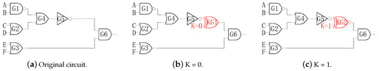
Figure 1.
Logic encryption through inserting the key-gate.
Except for the key-gates, the key-gates’ locations play a pivotal role in resisting the attacks against logic encryption. For the rare nodes of the circuit, they are considered as the nodes that have rare values, and it is difficult to flip to rare values. When the rare nodes in the circuit are kept at “1” or “0”, the changes of the inputs cannot cause the flipping of the rare nodes, which will undoubtedly increase the difficulty of the attackers to crack the keys. For the encrypted circuits, the circuit size is much larger than basic functional circuits, and the circuit structure is more complex. If the attackers want to crack the keys of logic encryption and obtain the internal information of the encrypted circuit, the key nodes should be firstly located in the circuit, such as the rare nodes in the circuit [16]. Rare node analysis can not only increase the complexity of analyzing circuit structure for the attackers, but also make the output entropy maximized when the wrong key is applied. In other words, the attackers cannot determine the secret key by analyzing the circuit structure to recover the original design. Moreover, when the wrong keys are applied, the 50% Hamming distance should be achieved as this value maximizes the entropy [17].
2.4. Path Sensitization Attack
Multiple attacks have been presented against existing logic encryption techniques including path sensitization attack, SAT based attack [6,14,18,19], logic cone analysis based attack [7], and hill-climbing attack [8]. Although SAT based attack is among the most exploited solutions, one-way random functions (ORF), such as advanced encryption standard (AES) with a fixed secret key, can resist SAT based attack through preventing the attackers from determining the inputs from its output values, as illustrated in Figure 2. K1 key-inputs are the fixed secret keys with AES, and the remaining K2 key-inputs are the keys of logic encryption. The primary output of the circuit is related to the ORF circuit; thus, the attackers cannot get the inputs through the output values of the circuit.
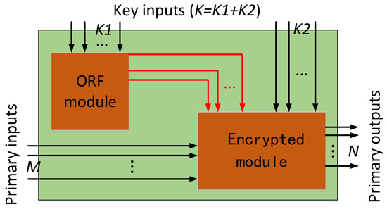
Figure 2.
One-way random functions (ORF) based countermeasure against SAT (satisfiability checking) based attacks. K1 out of K key-inputs in the encrypted netlist is connected to the ORF circuit.
Logic cone analysis based attack and hill-climbing attack evolved from path sensitization attack. Therefore, one design can withstand logic cone analysis based attack and hill-climbing attack with modifications on the basis of resisting path sensitization attack. Path sensitization attack can crack the keys of logic encryption through selecting the appropriate input vectors and the comparison and analysis of the circuit output with the normal function of IC. The keys of key-gates can be cracked by observing outputs of both circuits if the designer does not take protective measures against these keys of key-gates. Consider the circuit shown in Figure 3a. Assume the outputs of the gates G14, G15, and G10 have been selected as the inserted key-gates’ locations. Figure 3b shows the encryption circuit for inserting the key-gates into the determined locations. The keys of logic encryption, including K1, K2, and K3, can be cracked through path sensitization attack. The attackers utilize the input of the circuit to control n1 of G16 to crack the key K1 through observing the output O1 of G16. The inputs of the circuit can be set to 1001xxxxxxxxxxx, n1 set to one as the wire, and n1 is determined by I1, I2, I3, and I4, as shown in Figure 3c. Similarly, the output of G13 makes the key-gate KG2 sensitive through setting the wire n2 to one. The inputs of circuit can be set to xxxxxxxx00xxxxx and the wire n2 set to one as the wire n2 is determined by I9 and I10. Based on the above process, the attackers can crack the key-inputs. After cracking the key-input K2, the key-input K3 can also be cracked through setting the input of circuit xxxxxxxxxx0011x, as the wire n5 is determined by inputs I11, I12, I13, and I14.
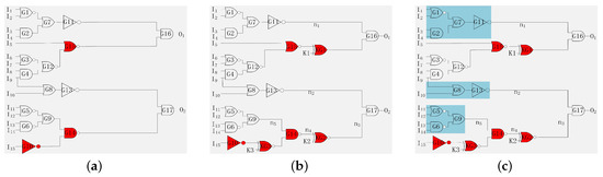
Figure 3.
Security threats against path sensitization attack. (a) An example circuit. (b) Circuit encrypted with three key-gates. (c) Path sensitization attack.
3. Framework of the Enhanced Logic Encryption Method
In this section, an enhanced logic encryption method is proposed. The encryption process is classified into three stages.
3.1. Fully Correlated Key Interdependency Block
In order to increase the correlation of the keys used in logic encryption, a fully correlated key interdependency block is added to the design to generate secondary keys. The block utilizes primary keys, which are connected to the outside inputs, to generate the new high-correlation secondary keys, which are connected to the inserted key-gates. The key interdependency block with 16 key-inputs is demonstrated in Figure 4.
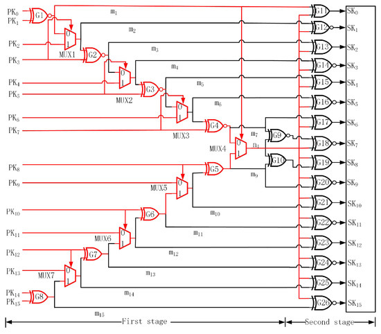
Figure 4.
Proposed key interdependency block with 16 key-inputs.
The whole block is composed of XOR, XNOR, and multiplexers that are connected to each other, which greatly increases the correlation of the block inputs. The block of proposed key interdependency can be divided into two parts that are adjacent to each other. The first part of the top is comprised of XNOR and multiplexers. The bottom is comprised of XOR and multiplexers. To increase high interference among the keys, the n1 wire will be generated. As shown in Figure 4, represents the primary key and represents the secondary key. For the n1 wire, it is associated with all primary keys. When any primary input changes, the value of n1 will change accordingly and affect the 16 key-gates, which is exhibited utilizing red wires in Figure 4. The second stage is comprised of XNOR and XOR gates. The reason for choosing XOR/XNOR in the second stage is that it is more difficult for the attackers to analyze the key-gates, because either XOR or XNOR is used as the key-gates of logic encryption, which increases the confusion of the attackers. From the functional perspective of XOR/XNOR, the output of XOR/XNOR depends on multiple inputs, which leads to a higher correlation between inputs and outputs.
3.2. Rare Node Analysis for Key-Gates’ Locations
In this phase, the rare node selection algorithm is utilized for key-gates’ location selection. Generally, the transition probability (Pt) is used to estimate the number of clock cycles required to generate a transition on a net as shown in Equation (3): P0 represents the probability of the node being zero; P1 represents the probability of the node being one; T0 represents the time of the node being zero; T1 represents the time of the node being one; and T represents the test time.
The switching probability (Ps) represents a node that turns from zero to one or one to zero, as defined in Equation (4). represents the number of node switching, and the number of test vectors applied in combinational logic circuits or the number of clock cycles applied in sequential circuits. The rare nodes refer to the nodes with lower switching probability and lower transition probability than the probability threshold (Pth) [20], namely Pt < Pth and Ps < Pth.
In order to set a reasonable Pth, there are several parameters that should be considered. These parameters are divided into two categories: authentication and circuit. Authentication parameters consist of two sub-parameters: (1) detection time for each integrated circuit and (2) clock cycle of testing . Circuit parameters consist of three sub-parameters: (1) the number of required transitions in circuit , (2) the average number of clock cycles per transition, which can be modeled using a geometric distribution (GD) [21], and (3) circuit activity . Equation (5) shows how the authentication and circuit parameters are related. The equation is based on the time at which a certain number of transitions occurs within a gate.
Algorithm 1 is proposed to find the rare nodes of the netlist circuit. The gate level netlist is required in the process, and the list of random patterns together with the time of simulation patterns are also required as the inputs of the algorithm. Then, every rare node is traversed, and Pth is calculated, then Ts and are utilized as the intermediate values to calculate Ps. Considering the range of Pth, the rare nodes are selected.
| Algorithm 1 Key-gate location strategy based on rare nodes. | |
| Require: | |
| 1: G | ▹ Gate level netlist. |
| 2: P | ▹ List of random patterns. |
| 3: t | ▹ Stimulation patterns of time. |
| Ensure: R | ▹ List of rare nodes. |
| 4: , P, G; | |
| 5: ; | |
| 6: for Each element p in P do | |
| 7: , P, t; | |
| 8: ; | |
| 9: end for | |
| 10: Set Pth; | |
| 11: R ← Pth, Pt, Ps; | |
3.3. Enhanced Logic Encryption Methodology
To resist attacks based on path sensitization attack, an optimized pairwise key-gates insertion methodology is proposed. Consider the circuit shown in Figure 3c. The key-inputs KG1, KG2, and KG3 can be cracked through path sensitization attack. The key-input K1 is propagated to the output O1 of the gate G16. The key to resist attacks based on path sensitization attack is to analyze whether the input cone dependency (ICOD) of gate G16 contains key-gates. Assuming that no key-gate exists, as shown in Figure 5a, a key-gate (KG4) is inserted to prevent attackers from finding sensitive paths for the keys of logic encryption. The key-inputs K1 and K4 cannot be cracked because the two key-inputs are restricted. Similarly, the key-input K2 is propagated to the output of the gate G17, so the ICOD of the other input n2 does not contain key-gates, and the key-gate (KG5) is inserted as shown in Figure 5b. Next, as the key-input K3 is propagated to the output of the gate G14, the ICOD of the other input n5 does not contain key-gates, and the key-gate (KG6) is inserted. Figure 5c shows the final encrypted circuit, where the keys of pairwise key-gates cannot be cracked as the key-inputs are restricted.
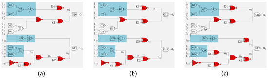
Figure 5.
Preventing path sensitization attack. (a) Modified (K1) circuit. (b) Modified (K2) circuit. (c) Modified (K3) circuit.
For the sake of realizing the key-gates’ insertion, a logic encryption algorithm is proposed that considers the locations of the inserted key-gates. Whether from the attackers’ or the defenders’ point of view, the Hamming distance between the correct and wrong outputs represents the validity of logical encryption. For attackers, they expect the Hamming distance to be as far as possible away from 50%, which is very helpful to crack the secret keys. For defenders, however, they expect the Hamming distance to be as close as possible to 50%, which makes it more difficult for attackers to crack secret keys. The Hamming distance between the correct and wrong outputs is related to the locations of key-gates and the correlation of key-inputs. Algorithm 2 is proposed to determine the locations of the key-gates based on rare node analysis and to resist attacks based on path sensitization attack. It utilizes the original gate level netlist with the key interdependency block and the list of rare nodes to produce an encrypted design netlist. First, the locations for key-gates are identified through the rare node analysis. Second, the key-gates are inserted into the selected locations by selecting the key values. A key-gate is then checked to withstand sensitization of the inserted key-gates, and this procedure keeps on iterating until all the key-gates are checked. Finally, the netlist is updated to the encrypted version after checking all the ICOD of the other inputs of the key-gates.
| Algorithm 2 Proposed logic encryption algorithm. | |
| Require: | |
| 1: ODN | ▹ Original design netlist. |
| 2: LOI | ▹ Locations of insertion. |
| 3: NOR | ▹ Number of rare nodes. |
| 4: RN | ▹ List of rare nodes. |
| Ensure: EDN | ▹ Encrypted design netlist. |
| 5: ; | ▹ Search for key-gate’s locations utilizing the rare nodes analysis method. |
| 6: for ( to ) do | |
| 7: if then | |
| 8: ; | ▹ A key-gate is inserted into the rare node. |
| 9: ; | ▹ Mark the gate whose input is directly connected to the key-gate. |
| 10: ; | ▹ Determine the ICODbased on the marked gate(s). |
| 11: ; | ▹ Search for the nodes without key-gates. |
| 12: ; | ▹ Update the EDNby inserting key-gates. |
| 13: end if | |
| 14: end for | |
4. Experimentation
4.1. Experimental Setup
In this section, the methodology proposed in this paper is validated through the experiments on both basic functional circuits and one representative encryption circuit, which are the ISCAS’85 benchmarks [22] and advanced encryption standard (AES) circuit. These circuits are synthesized through Synopsys Design Compiler utilizing the SMIC180 nm technology library to generate the gate level netlist. To collect the required information for the experiments, first, the insertion location of key-gates in logic encryption is extracted through rare node analysis. Second, the 16 bit, 64 bit, and 128 bit keys’ interdependency blocks are integrated with circuits and synthesized using Synopsys Design Compiler. After that, the circuits are encrypted utilizing the method described in Section 3.3. Finally, the encrypted circuits are re-synthesized, and the area overhead is calculated. To assess the efficiency of the key interdependency blocks in generating peculiar secondary keys, the 16 bit, 64 bit, and 128 bit keys were applied to the interdependency block, and the secondary keys were observed. A total of 10 K random patterns were applied to the circuits, and based on the simulation results, for the 16 bit keys, the 3% conditions of the dependency block generated the same output for two or more different input combinations. For the 64 bit keys, the 1% conditions of the key interdependency block generated the same output for two or more different input combinations, and the 128 bit was 0.4%.
4.2. Rare Node Analysis
As the first step, the rare nodes of the circuits were analyzed utilizing the transition and switching probabilities. Table 1 exhibits the distribution of Pt and Ps based on the inputs. According to Equation (5), Pth for the transition probability was set to 0.1 and Pth for the switching probability was set to 0.2 [23,24,25]. The rare nodes were those whose Pt and Ps were smaller than Pth, but not those whose Pt and Ps were 0. If the Pt and Ps were 0, this indicated the nodes in the circuit that were always connected to GND or VDD. The number of rare nodes in each circuit based on Pt and Ps is shown in Table 1. For circuits with simpler internal connections like c432, c2670, c5315, and c6288, the number of rare nodes in these circuits was less than 8%. However, for more complex circuits like c1908, c3540, and AES, the number of rare nodes were around 17.4%, 20%, and 13.8%, respectively. After analyzing the nodes found above, rare nodes of the circuits were identified. Then, the locations of the key-gates based on rare nodes were determined to encrypt the netlist.

Table 1.
Table of the number of nodes based on and .
4.3. Output Corruption Analysis
After the rare nodes were identified, the key interdependency block was merged and connected with the netlist, and the key-gates were inserted utilizing the enhanced method. The secondary keys, which were generated through the key interdependency block, were directly connected to the key-gates. A set of 1000 wrong keys were randomly provided to the encrypted netlist, and output corruption between the observed outputs and the correct outputs was analysis. Figure 6 exhibits the Hamming distances when the wrong keys were applied to the netlist. The Hamming distance for the circuits (except c432) were within 46% to 50%, when encrypted with 128 bit keys. For those smaller circuits, like c432 with only 120 gates, their input and output numbers were very small (only 43), and the number of rare nodes was also very small (only 9). Therefore, whether the key size was 16 bit, 64 bit, or 128 bit, when the key changed, the Hamming distance of the c432 circuit would hardly change (approximately 34%). The 64 bit keys could produce up to 44% to 46%, while the corruption was approximately 42% to 45% for 16 bit keys. In [15], the output corruption with 128 bit keys reached 45% to 50%. The output corruption with 64 bit keys reached 38% to 44%, while the output corruption with 96 bit keys was approximately 42% to 47%. Compared to [15], the output corruption through our method improved the percentage of the output corruption by 5% for 64 bit keys.
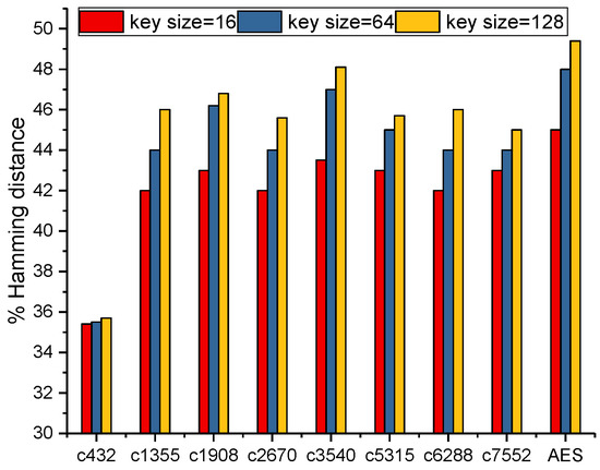
Figure 6.
Hamming distance for wrong keys.
As mentioned previously, hill-climbing attack and logic cone analysis attack were evolved from path sensitization attack. The essence of the above three attack methods is the same for cracking the keys of logic encryption. To estimate the resistance of the enhanced logic encryption against the above attacks, the Hamming distance between the observed and the correct output was calculated to evaluate the validity of resisting the above attacks. Whether these three attacks could successfully crack the keys of logic encryption was closely related to the number of wrong keys. The number of wrong keys was gradually decreased, and the difference was analyzed based on Hamming distance with rare node analysis without the key interdependency block and rare node analysis with the key interdependency block. Figure 7 shows the output corruption percentage between the rare node analysis method without and with the key interdependency block with 128 bit primary keys for the wrong key bit percentage for ISCAS’85 benchmarks [22] and the AES circuit. The percentage of the output corruption characterized the Hamming distance between the observed and the correct output. When the percentage of wrong primary key bits decreased, the consequent percentage of the output corruption also decreased without the key interdependency block. The percentage of the output corruption and the percentage of wrong key bits formed an approximate linear dependence, which could help the attackers crack the keys of logic encryption. However, as the percentage of wrong primary key bits in the key interdependency block decreased, the percentage of corrupted output did not decrease dramatically. The output corruption for 2% wrong primary key bits was 15% to 25%, while for the same number of wrong primary key bits, the logic encryption without key interdependency block produced 2% to 5% of output corruption. Furthermore, the output corruption reached 40% for wrong primary key bits with the key interdependency block, while 45% for wrong primary key bits without the key interdependency block. This was because the key interdependency block interfered with the keys greatly. Thus, attackers did not converge to correct keys. In the key interdependency block, the wrong bit of primary key pushed all secondary keys, which made it more difficult for attackers to crack the keys of logic encryption. The proposed logic encryption with the key interdependency block, which produced high output corruption, limited the cracking of the keys of logic encryption utilizing attacks based on the path sensitization attack.
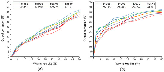
Figure 7.
Comparison of the Hamming distance between the logic encryption without and with the key interdependency block for the wrong key bits. (a) Hamming distance for % wrong key bits without the key interdependency block. (b) Hamming distance for the wrong key bits with the key interdependency block.
4.4. Area Overhead Analysis
In our experiment, the 16 bit, 64 bit, and 128 bit key interdependency blocks were integrated with the circuits, and the area overhead of the enhanced logic encryption was evaluated. Figure 8 shows the area overhead for different key sizes with and without key interdependency blocks in ISCAS’85 benchmarks, respectively. In Figure 8, the tags with “key = 16 with KD”, “key = 64 with KD”, and “key = 128 with KD” represent the area overhead of the enhanced logic encryption for 16 bit, 64 bit, and 128 bit key interdependency blocks, respectively. In order to show the proportion of the area overhead of key interdependency blocks in the circuit, the logic encryption method without the key interdependency block was designed [1,5,26]. The tags “key = 16 W/O KD”, “key = 64 W/O KD”, and “key = 128 W/O KD” in Figure 8 represent the area overhead of the logic encryption method without the key interdependency block for 16 bit, 64 bit, and 128 bit key interdependency blocks, respectively. The area overhead of the key interdependency blocks for different key bits in the same circuit was different, and the area overhead of the key interdependency blocks for the same key bits in various scale circuits also varied. For small sized circuits, like c432, c1355, c1908, and c2670 with less than 1k gates, the area overhead increased approximately 15% for 128 bit keys, while 10% for 64 bit keys and 3% for 16 bit keys. Still, for larger sized circuits, like c3540, c5315, c6288, and c7552 with more than 1k gates but less than 3k gates, the area overhead of 128 bit keys was 10%, while 5% for 64 bit keys and scarcely increasing for 16 bit keys. Furthermore, for the AES circuit, which had around 50k gates, the area overhead of 128 bit keys was 4%, while hardly increasing for 64 bit keys and 16 bit keys. Thus, the enhanced logic encryption method could protect these circuits at the expense of reasonable area overhead through selecting different key-sizes. Circuits (c432, c1355, c1908, and c2670) should utilize 16 bit keys to guarantee that the percentage of area overhead is under 3%. Circuits (c3540, c5315, c6288, and c7552) should utilize 64 bit keys to guarantee that the percentage is under 5%. The AES circuit should utilize 128 bit keys to guarantee the percentage under 10%.
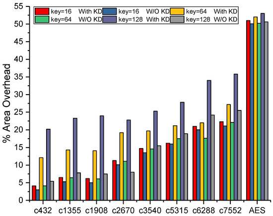
Figure 8.
Area overhead for different key-sizes with and without the key interdependency block.
A comparison analysis was performed with the results in [15], and Figure 9 shows a comparison of the area overhead of the proposed method and [15] when the key-size was 64 bit and 128 bit, respectively. The area overhead of the proposed key interdependency block for small sized circuits, like c432, c1355, c1908, c2670, c2670, c3540, c5315, c6288, and c7552 with less than 3k gates, was approximately 3% less than that of [15] when the key-size was 64 bit, while approximately 5% less for the 128 bit keys. However, for larger sized circuits, like the AES circuit with around 50k gates, the area overheads of the proposed method and [15] were almost the same. Therefore, the area overhead was acceptable for the different circuits through selecting different key-sizes.
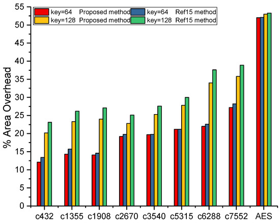
Figure 9.
Area overhead for the proposed method and Reference [15] method.
4.5. An Illustrative Minimum Working Example
An illustrative minimum working example (MWE) is demonstrated with details in the process of carrying out experiment on benchmark c432. Overall, the whole flow of our framework first synthesized the circuit into the gate level netlist, then the information was extracted from the files utilizing automatic scripts, and the results were calculated based on the data. The benchmarks utilized in this paper were developed in register-transfer level (RTL) code, and the Design Compiler (DC, Version 2010.03-SP5-2) was utilized to synthesis the RTL code into the gate level netlist. After the gate level netlist was available, Verilog Compiler Simulator (VCS, Version 2010-06) was utilized to carry out gate level simulation with random stimuli. The Switching Activity Interchange Format (*.saif) file was utilized to log the node switching probabilities, then a shell script (saif_data.sh) was used to rand the probabilities from low to high. With the pre-set threshold (refer to Section 3.2), the rare nodes with low switching probabilities were sorted out, and the nodes together with their corresponding switching probabilities were saved in *.txt format files. Note that the nodes with no switching probabilities were removed because these nodes were usually connected directly to VDD or GND in the circuit. The above mentioned intermediate files are illustrated as fragments in Figure 10. With the consideration that the whole process was handled utilizing automatic scripts, our method should have good scalability ability, but the processing time may be long. For future work, we will validate our framework on big ICs with millions of gates.
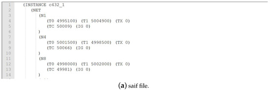
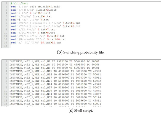
Figure 10.
Fragments of the files and scripts utilized in the minimum working example (MWE).
5. Conclusions
In this paper, an enhanced logic encryption method was proposed with a fully correlated key interdependency block to withstand security vulnerabilities. The Hamming distance and high correlation between primary keys and secondary keys were taken as the assessment criteria. The proposed method satisfied the characteristics of the interdependency between the keys and output corruption to resist attacks based on path sensitization attack. The insertion locations of the XOR/XNOR gates were determined through rare node analysis. The Hamming distance of the result was close to 50%, which made it possible to improve the security of logic encryption circuit by utilizing the proposed method. To resist attacks including hill-climbing attack, logic cone analysis attack, and path sensitization attack, the correlation between primary keys and secondary keys reached 98%. Furthermore, for the 16 bit keys, 3% of the cases of the dependency block generated the same output for two or more different input combinations. For the 64 bit keys, 1% of the cases of the key interdependency block generated the same output for two or more different input combinations, and the 128 bit key was 0.4%. Although the enhanced logic encryption demanded additional hardware, the area overhead, which restricted the area overhead to under 10%, was acceptable for the circuits by selecting different key-sizes.
6. Discussion
The enhanced logic encryption method can encrypt the netlist through selecting different key sizes to increase the difficulty for attackers to crack the keys of logic encryption based on path sensitization attack. For the SAT based attack, however, it has gradually attracted the attention of researchers because of the feasibility and complexity of SAT based attack. The insight of SAT based attack is to determine a set of distinguishing I/O patterns through iteratively settling a sequence of SAT formulas, which can gradually crack the correct keys through eliminating wrong key combinations till none exist. Meanwhile, the complexities of the SAT problems and the number of executed SAT settling calls determines the efficiency of the SAT based attack. Still, in our work, the combination of the original netlist and the key interdependency block added additional circuit complexity, and a circuit encrypted with sufficiently large keys could be implemented in one-way random function circuits. Attackers can crack the secret keys of most logic encryption through SAT based attack in the case of increasing the time overhead even for an appropriately large key size. The ORF circuits in this work were proposed to increase the difficulty of executing an SAT based attack; however, the ORF circuit included an encryption circuit like the AES circuit, and the area overhead of the ORF circuit was relatively large. Although the protection was effective, the modified SAT based attacks such as AppSAT [27] and Double DIP [28] can threaten the level of security of the ORF circuits. Based on this fact, novel structures and methodologies should be explored, which can increase the number of iterations of the SAT based attack and increase the difficulty for attackers to crack secret keys of logic encryption. The focus of our future work, therefore, is to enhance the resiliency of in-cone logic encryption against the SAT based attack and explore new structures and methodologies guaranteeing reasonable overhead.
Author Contributions
Conceptualization, J.H., K.S., and Y.Z.; methodology, J.H. and H.M.; software, J.H.; validation, H.M.; data curation, K.S.; resources, Y.Z.; writing, review and editing, J.H.; project administration, Y.Z.
Funding
This research was partially funded by the National Natural Science Foundation of China (61832018) and the China Postdoctoral Science Foundation (2019TQ0167).
Conflicts of Interest
The authors declare no conflict of interest.
References
- Yasin, M.; Rajendran, J.J.; Sinanoglu, O.; Karri, R. On Improving the Security of Logic Locking. IEEE Trans. Comput.-Aided Des. Integr. Circuits Syst. 2016, 35, 1411–1424. [Google Scholar] [CrossRef]
- Shen, Y.; Rezaei, A.; Zhou, H. SAT based bit-flipping attack on logic encryptions. In Proceedings of the 2018 Design, Automation Test in Europe Conference Exhibition (DATE), Dresden, Germany, 19–23 March 2018; pp. 629–632. [Google Scholar] [CrossRef]
- Guin, U.; Zhou, Z.; Singh, A. Robust Design-for-Security Architecture for Enabling Trust in IC Manufacturing and Test. IEEE Trans. Very Large Scale Integr. Syst. 2018. [Google Scholar] [CrossRef]
- Aitken, R. Panel: Is design-for-security the new DFT? In Proceedings of the Vlsi Test Symposium, Napa, CA, USA, 27–29 April 2015. [Google Scholar]
- Rajendran, J.; Zhang, H.; Zhang, C.; Rose, G.S.; Pino, Y.; Sinanoglu, O.; Karri, R. Fault Analysis-Based Logic Encryption. IEEE Trans. Comput. 2015, 64, 410–424. [Google Scholar] [CrossRef]
- Taatizadeh, P.; Nicolici, N. An automated SAT based method for the design of on-chip bit-flip detectors. In Proceedings of the IEEE/ACM International Conference on Computer-Aided Design, Irvine, CA, USA, 13–16 November 2017. [Google Scholar]
- Yu, W.L.; Touba, N.A. Improving logic obfuscation via logic cone analysis. In Proceedings of the 2015 16th Latin-American Test Symposium (LATS), Puerto Vallarta, Mexico, 25–27 March 2015; pp. 1–6. [Google Scholar]
- Plaza, S.M.; Markov, I.L. Solving the Third-Shift Problem in IC Piracy With Test-Aware Logic Locking. IEEE Trans. Comput.-Aided Des. Integr. Circuits Syst. 2015, 34, 961–971. [Google Scholar] [CrossRef]
- Karmakar, R.; Chattopadhyay, S.; Kapur, R. Enhancing security of logic encryption using embedded key generation unit. In Proceedings of the 2017 International Test Conference in Asia (ITC-Asia), Taipei, Taiwan, 13–15 September 2017; pp. 131–136. [Google Scholar] [CrossRef]
- Karmakar, R.; Kumar, H.; Chattopadhyay, S. On Finding Suitable Key-Gate Locations In Logic Encryption. In Proceedings of the 2018 IEEE International Symposium on Circuits and Systems (ISCAS), Florence, Italy, 27–30 May 2018; pp. 1–5. [Google Scholar] [CrossRef]
- Chakraborty, R.S.; Bhunia, S. HARPOON: An Obfuscation-Based SoC Design Methodology for Hardware Protection. IEEE Trans. Comput.-Aided Des. Integr. Circuits Syst. 2009. [Google Scholar] [CrossRef]
- Roy, J.A.; Koushanfar, F.; Markov, I.L. Ending Piracy of Integrated Circuits. Computer 2010, 43, 30–38. [Google Scholar] [CrossRef]
- Yasin, M.; Mazumdar, B.; Rajendran, J.J.V.; Sinanoglu, O. SARLock: SAT attack resistant logic locking. In Proceedings of the 2016 IEEE International Symposium on Hardware Oriented Security and Trust (HOST), McLean, VA, USA, 3–5 May 2016; pp. 236–241. [Google Scholar] [CrossRef]
- Xie, Y.; Srivastava, A. Anti-SAT: Mitigating SAT Attack on Logic Locking. IEEE Trans. Comput.-Aided Des. Integr. Circuits Syst. 2019, 38, 199–207. [Google Scholar] [CrossRef]
- Karmakar, R.; Prasad, N.; Chattopadhyay, S.; Kapur, R.; Sengupta, I. A New Logic Encryption Strategy Ensuring Key Interdependency. In Proceedings of the International Conference on Vlsi Design & International Conference on Embedded Systems, Hyderabad, India, 7–11 January 2017. [Google Scholar]
- Dupuis, S.; Ba, P.; Di Natale, G.; Flottes, M.; Rouzeyre, B. A novel hardware logic encryption technique for thwarting illegal overproduction and Hardware Trojans. In Proceedings of the 2014 IEEE 20th International On-Line Testing Symposium (IOLTS), Girona, Spain, 7–9 July 2014; pp. 49–54. [Google Scholar] [CrossRef]
- Rajendran, J.; Garg, S. Logic Encryption. In Hardware Protection through Obfuscation; Forte, D., Bhunia, S., Tehranipoor, M., Eds.; Springer: Cham, Switzerland, 2017. [Google Scholar]
- Hai, Z.; Jiang, R.; Kong, S. CycSAT: SAT based attack on cyclic logic encryptions. In Proceedings of the 2017 IEEE/ACM International Conference on Computer-Aided Design (ICCAD), Irvine, CA, USA, 13–17 November 2017. [Google Scholar]
- Zaikin, O.; Kochemazov, S. An Improved SAT-Based Guess-and-Determine Attack on the Alternating Step Generator. In Proceedings of the Information Security: 20th International Conference, ISC 2017, Ho Chi Minh City, Vietnam, 22–24 November 2017. [Google Scholar]
- Salmani, H.; Tehranipoor, M.; Plusquellic, J. A Novel Technique for Improving Hardware Trojan Detection and Reducing Trojan Activation Time. IEEE Trans. Very Large Scale Integr. Syst. 2011, 20, 112–125. [Google Scholar] [CrossRef]
- Wackerly, D.; Mendenhall, W.; Scheaffer, R.L. Mathematical Statistics with Applications; Thomson Brooks/Cole: Belmont, CA, USA, 2008. [Google Scholar]
- Hansen, M.C.; Yalcin, H.; Hayes, J.P. Unveiling the ISCAS-85 benchmarks: A case study in reverse engineering. IEEE Des. Test Comput. 1999, 16, 72–80. [Google Scholar] [CrossRef]
- Saha, S.; Chakraborty, R.S.; Nuthakki, S.S.; Anshul; Mukhopadhyay, D. Improved Test Pattern Generation for Hardware Trojan Detection Using Genetic Algorithm and Boolean Satisfiability. In Proceedings of the CHES 2015: 17th InternationalWorkshop, Cryptographic Hardware and Embedded Systems, Saint-Malo, France, 13–16 September 2015. [Google Scholar]
- Huang, Y.; Bhunia, S.; Mishra, P. MERS: Statistical Test Generation for Side-Channel Analysis based Trojan Detection. In Proceedings of the ACM Sigsac Conference on Computer and Communications Security, Vienna, Austria, 24–28 October 2016; pp. 130–141. [Google Scholar]
- Chakraborty, R.S.; Wolff, F.; Paul, S.; Papachristou, C.; Bhunia, S. MERO: A Statistical Approach for Hardware Trojan Detection. In International Workshop on Cryptographic Hardware and Embedded Systems; Springer: Berlin/Heidelberg, Germany, 2009; pp. 396–410. [Google Scholar]
- Roy, J.A.; Koushanfar, F.; Markov, I.L. Ending Piracy of Integrated Circuits. In Proceedings of the 2018 Design, Automation & Test in Europe, Munich, Germany, 10–14 March 2008; pp. 30–38. [Google Scholar]
- Shamsi, K.; Li, M.; Meade, T.; Zhao, Z.; Pan, D.Z.; Jin, Y. AppSAT: Approximately deobfuscating integrated circuits. In Proceedings of the 2017 IEEE International Symposium on Hardware Oriented Security and Trust (HOST), Mclean, VA, USA, 1–5 May 2017; pp. 95–100. [Google Scholar] [CrossRef]
- Shen, Y.; Zhou, H. Double DIP: Re-Evaluating Security of Logic Encryption Algorithms. In Proceedings of the on Great Lakes Symposium on VLSI 2017, Banff, AB, Canada, 10–12 May 2017. [Google Scholar]
© 2019 by the authors. Licensee MDPI, Basel, Switzerland. This article is an open access article distributed under the terms and conditions of the Creative Commons Attribution (CC BY) license (http://creativecommons.org/licenses/by/4.0/).