Article

A Hybrid Asymptotic-FVTD Method for the Estimation of the Radar Cross Section of 3D Structures

Department of Electrical, Electronic, Telecommunications Engineering and Naval Architecture (DITEN), University of Genoa, 16145 Genoa, Italy
*
Author to whom correspondence should be addressed.
Electronics 2019, 8(12), 1388; https://doi.org/10.3390/electronics8121388
Submission received: 19 October 2019 / Revised: 30 October 2019 / Accepted: 17 November 2019 / Published: 21 November 2019

Abstract

:
The Finite Volume Time-Domain (FVTD) method is an effective full-wave technique which allows an accurate computation of the electromagnetic field. In order to analyze the scattering effects due to electrically large structures, it can be combined with methods based on high-frequency approximations. This paper proposes a hybrid technique, which combines the FVTD method with an asymptotic solver based on the physical optics (PO) and the equivalent current method (ECM), allowing the solution of electromagnetic problems in the presence of electrically large structures with small details. Preliminary numerical simulations, aimed at computing the radar cross section of perfect electric conducting (PEC) composite objects, are reported in order to evaluate the effectiveness of the proposed method.

1. Introduction

Several electromagnetic problems require solvers able to characterize complex and multi-scale structures [1,2,3,4]. To this end, two main classes of approaches can be identified. The first one is composed by full-wave approaches, which aim to solve Maxwell’s equations (or equivalent equations derived from them) without approximations different from the ones introduced by the numerical discretization of the problem. Common solvers belonging to such a class are the method of moments (MoM) [5], the finite-difference time-domain (FDTD) [6] and finite-difference frequency-domain (FDFD) [7] methods, the finite integration technique (FIT) [8], the finite-element method (FEM) [9], and the method of lines (MOL) [10]. Although being very effective in several practical applications, these approaches have the drawback that the computational requirements usually increase significantly when very large (in terms of wavelengths) radiating or scattering structures are considered. In such cases, high-frequency techniques based on asymptotic approximations are frequently adopted. Common methods belonging to this second class are based on the physical optics (PO) approximation and on the geometrical/physical theory of diffraction [9,11].
When targets composed by large and small scatterers are concerned, hybrid methods, in which full-wave and high-frequency techniques are combined together, can also be adopted. In this framework, different hybrid formulations have been proposed in the literature in the past years. For example, the method of moments has been combined with different high-frequency solvers, both for characterizing the radiation of antennas in the presence of large structures [12,13,14,15], and for computing the field scattered by large or multi-scale objects [16,17,18]. Iterative techniques have also been proposed for increasing the accuracy and reducing the computational time [19,20]. Time-domain approaches, such as the FDTD and FIT methods, have been adopted in combination with asymptotic algorithms, too [21,22,23,24,25]. It is worth remarking that, in several cases, one of the main difficulties in developing hybrid methods is represented by the design of a correct interface between the full-wave and asymptotic solver. To partially overcome such a problem, the use of Green’s functions, including the scattering contributions from the large scatterers present in the simulated scenario, has also been proposed [26,27,28].
In this paper, a hybrid approach based on the Finite Volume Time-Domain (FVTD) method [3,29,30,31], which is a full-wave technique based on a finite-volume discretization of Maxwell’s equations, is proposed. The FVTD method has been successfully used in several applications [32,33,34,35] concerning both perfect electric conducting (PEC) and dielectric targets, and even in combination with other approaches. For example, full-wave FVTD/FDTD techniques have been proposed in [36,37], whereas in [38], a hybrid FVTD/PO method has been developed and applied to two-dimensional (2D) structures. In the present paper, the FVTD method is combined with an asymptotic technique in order to analyze the radar cross section (RCS) of three-dimensional (3D) structures. In particular, the FVTD solver is used for computing the scattering contributions due to one or more small dielectric or metallic objects, whereas the asymptotic solver is adopted for including the effects of large metallic structures located nearby them. The initial idea concerning such a hybridization has been firstly reported in [39], where it has been used for characterizing antennas near large metallic structures. In that case, however, only sources internal to the FVTD region were handled and only the PO contributions due to the nearby metallic structures were included. In the present work, the proposed hybrid technique is extended for the first time in order to include more scattering contributions from the asymptotic region. To this end, the PO approximation is adopted for computing the scattered fields from smooth surfaces, whereas the Equivalent Current Method (ECM) [11] is used for including the effects of the edges. As far as we know, this is the first time that such a hybrid approach is developed and numerically validated for 3D configurations.
The paper is organized as follows. The formulation of the hybrid method is reported in Section 2. Numerical results aimed at validating the proposed computational technique are provided in Section 3. Finally, conclusions are drawn in Section 4.

2. Formulation of the Hybrid Method

With reference to Figure 1, the computational domain is split into two parts, namely the FVTD region and the asymptotic region. In the first region, which contains an electrically small-size object, the FVTD solver is applied. In the second region, which is used for the electrically large structures, electromagnetic fields are calculated by using the asymptotic technique. In particular, the PO method is applied to compute the scattered field by the surfaces in which the asymptotic region is discretized, whereas edges are taken into account by using ECM.
The computational domain is illuminated by a plane wave, E I N C ( r ) = E I N C 0 e j k 0 d ^ t r , where d ^ t is the propagation direction, E I N C 0 describes the electric field amplitude and polarization, and k 0 is the vacuum wavenumber. The overall scattered electric field in the far-field region, indicated as E S C A T F F ( r ) , is approximately given by the following contributions:
E S C A T F F ( r ) E F V T D F F ( r ) + E P O F F ( r ) + E E C M F F ( r ) + E F V T D P O F F ( r ) + E F V T D E C M F F ( r )
The first term, E F V T D F F ( r ) , represents the electric field scattered by the object inside the FVTD region, whereas E P O F F ( r ) and E E C M F F ( r ) denote the primary electric fields scattered by the plane surfaces in which the asymptotic region is discretized and by their edges, respectively. However, these three terms do not take into account the interactions between the two regions. The most significant of these interactions are included in secondary scattered fields, denoted as E F V T D P O F F ( r ) and E F V T D E C M F F ( r ) . These two terms concern the field scattered by the objects located in the asymptotic region when illuminated by the field produced by the FVTD region.
The contribution produced by the field scattered by the asymptotic region and radiated onto the FVTD region is neglected, assuming that the latter region is significantly larger than the former one. Under this assumption, it is possible to simulate the FVTD region alone, and subsequently combine the result with the contributions due to the asymptotic region. The scattering problem is solved by adopting a proper discretization of both regions, as described in the following sections.

2.1. Scattered Field from the FVTD Region

The primary scattering contribution from the FVTD region is computed using the full-wave FVTD method. We adopt a discretization with tetragonal elementary volumes V n ( n = 1 , , N ) , whose faces are denoted as S n , k ( k = 1 , , 4 ) and characterized by outward unit vectors n ^ n , k . By defining the vector field U ( r , t ) = ( E x , E y , E z , H x , H y , H z ) t and using the second-order Lax–Wendroff temporal scheme [40], from Maxwell’s equations we obtain the following explicit update equations for each n th elementary volume [3],
U n ( i + 1 2 ) = U n ( i ) + Δ t 2 [ 1 V n k = 1 4 Λ n , k ( i ) S n , k A n 1 C n U n ( i ) ]
U n ( i + 1 ) = U n ( i ) + Δ t [ 1 V n k = 1 4 Λ n , k ( i + 1 2 ) S n , k A n 1 C n U n ( i + 1 2 ) ]
where the superscript i represents the time-step index and Δ t is its time-width, which is chosen to satisfy the stability criterion [3]. The term U n is the field vector computed at the center of the n th tetrahedron, whereas Λ n , k represents the field flux through the surface S n , k , which is related to the tangential component of electromagnetic field [1]. By applying the Monotonic Upwind Scheme for Conservative Laws (MUSCL) [1], it is possible to compute the value of the electromagnetic field at the center of each face, which is a quantity required for evaluating Λ n , k . The term A n 1 C n U n ( i ) takes into account the presence of media with finite electric conductivities. This term is computed by means of the Additive Induced Source Technique (AIST) [34]. In particular, A n is a matrix containing the values of the dielectric permittivity ϵ and magnetic permeability μ inside the n th subdomain, whereas C n is a matrix containing the values of the electric conductivity in the same volume element. Detailed definitions of these matrices can be found in [1]. At the boundaries of the simulation domain, Silver–Müller absorbing boundary conditions [1] are applied in order to remove the inward components of the flux at the boundary faces. Near-field to far-field (NFFF) transformations in the time-domain [6] are then used to compute the scattered electric and magnetic fields E F V T D F F and H F V T D F F outside the FVTD region, i.e., in test points and in both faces and edges of the asymptotic region. In order to compute the NFFF transformation, a proper Huygens surface is considered inside the FVTD region. Since the subsequent steps of the hybrid procedure are evaluated in the frequency-domain, the Fast Fourier Transform (FFT) is applied to FVTD results in order to compute the scattered field term E F V T D F F ( r ) at the considered frequency.

2.2. Scattered Field from the Asymptotic Region

The primary scattered field due to the asymptotic region, which is assumed to be composed of a PEC material, is computed by considering two different contributions. The first one is related to the scattering from surfaces and it is computed by using the PO method [11,41] in the frequency-domain. The scattered field is approximated with the field generated by the current density vector J P O , given by [42]
J P O ( r ) = { 2 n ^ ( r ) × H I N C ( r ) if   r   ϵ   S i l l 0 otherwise
where n ^ is the outward unit vector perpendicular to the illuminated part of the surface S i l l and H I N C ( r ) = d ^ t × η 0 1 E I N C ( r ) is the incident magnetic field vector at a point r on S i l l . Assuming that the illuminated surface S i l l is discretized into I triangular faces, S i , i = 1 , ,   I , the resulting scattered electric field can be expressed as [42]
E P O F F ( r ) = P O ( H I N C ) ( r ) = η 0 e j k 0 r j 2 λ 0 r i { N P O i ( r ^ ) [ N P O i ( r ^ ) r ^ ] r ^ }
where λ 0 is the wavelength, η 0 is the intrinsic impedance of the vacuum, and N P O i is the radiation vector related to the i th face, which is given by N P O i ( r ^ ) = S i J P O ( r ) e j k 0 r r ^ d r .
The second contribution is related to the edges. As previously mentioned, the ECM is used [11,41], which assumes that the scattered field due to the edges can be computed in terms of equivalent electric and magnetic line currents. With reference to the above discretization in triangular elements, this part of the scattered field is obtained by summing the contributions of each l th elementary edge [42] between adjacent triangles, i.e.,
E E C M F F ( r ) = E C M ( E I N C ,   H I N C ) ( r ) = η 0 e j k 0 r j 2 λ 0 r l { N E C M l ( r ^ ) [ N E C M l ( r ^ ) r ^ ] r ^ 1 η 0 r ^ × L E C M l ( r ^ ) }
where N E C M l and L E C M l are the electric and magnetic radiation vectors related to the l th edge, given by N E C M l ( r ^ ) = t ^ l C l I e ( r ) e j k 0 r r ^ d r and L E C M l ( r ^ ) = t ^ l C l I m ( r ) e j k 0 r r ^ d r , respectively, t ^ l being the unit vector defining the direction of the l th edge C l . The equivalent electric and magnetic currents I e and I m depend upon E I N C and H I N C , respectively, and are defined as in [41,43].

2.3. Scattered Fields Due to the Coupling between Regions

The secondary scattered fields E F V T D P O F F ( r ) and E F V T D E C M F F ( r ) are due to the coupling between the FVTD and the asymptotic regions. Such contributions are again computed by using the PO approximation and the ECM. However, in this case, the incident field is represented by the primary field scattered by the FVTD region in the points belonging to the asymptotic region. In this paper, we assume that the distance between the asymptotic and the FVTD regions is sufficiently large to allow the use of the far-field approximation for the computation of the fields E F V T D F F ( r ) and H F V T D F F ( r ) , r S i l l , that illuminate the asymptotic region. Consequently, the coupling terms can be compactly expressed as
E F V T D P O F F ( r ) = P O ( H F V T D F F ) ( r )
E F V T D E C M F F ( r ) = E C M ( E F V T D F F ,   H F V T D F F ) ( r )

3. Numerical Results

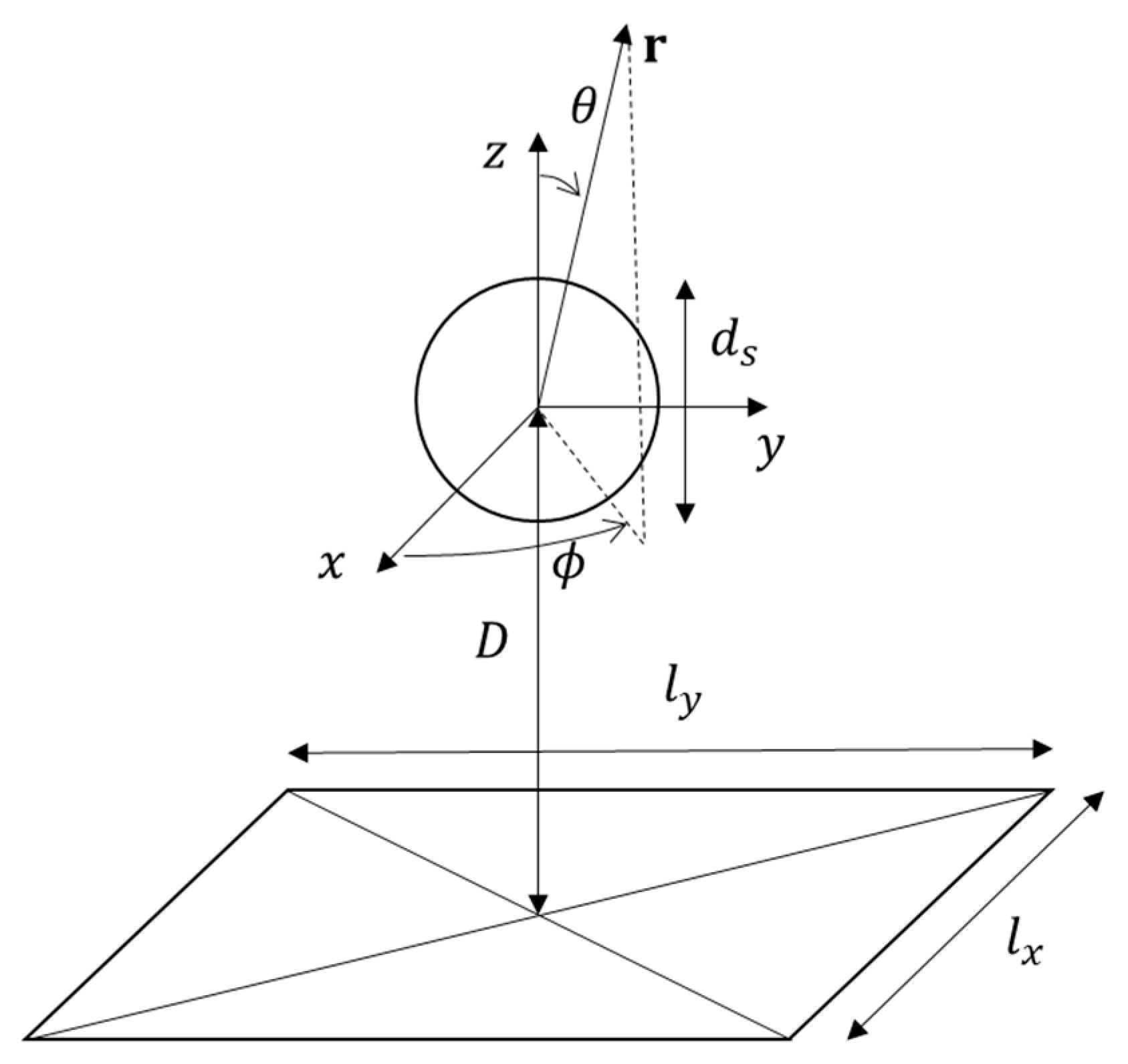
In this Section, some preliminary numerical results obtained by using the above hybrid method are reported. The first considered configuration is shown in Figure 2. A PEC sphere of diameter d S = 0.318   m is located over a PEC plate of sides l x = l y = 1   m . The distance between the center of the sphere and the plate is denoted as D . A standard spherical coordinate system centered on the sphere is assumed (in the following, as usual, θ and ϕ denote the elevation and azimuth angles, as shown in Figure 2). The incident field is a plane wave propagating in the directions ϕ = 0 ° , θ [ 0 ° ,   90 ° ] and polarized along the elevation direction θ ^ . In the FVTD solver, a Gaussian pulse with unit amplitude and time-width at half-maximum of 1 ns has been used. The simulation time has been set equal to 29 ns and the time step is Δ t = 3.4 ps. In this case, the FVTD region is a spherical volume of diameter d F V T D = 1   m , which has been discretized into N F V T D = 90,375 tetrahedra. The Huygens surface S H used for computing the NFFF transformations is a sphere of diameter d H = 0.6   m discretized with N H = 3572 triangles. Both the FVTD region and the Huygens surface are centered at the origin of the reference system. The asymptotic region is represented by the plate, which has been discretized with a mesh composed of N A S = 28 triangles.
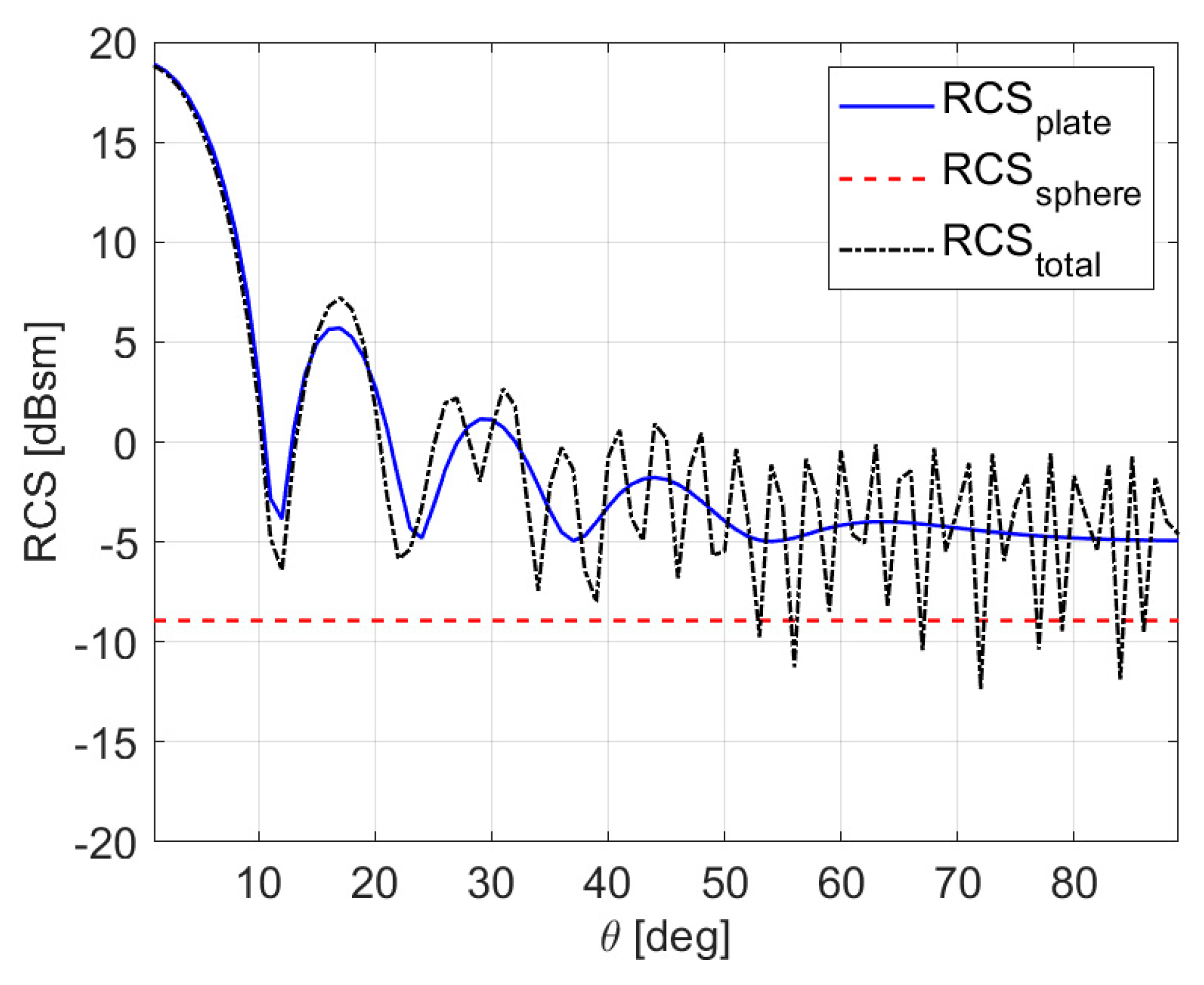
Figure 3 shows the monostatic RCS computed at 750 MHz for 0° θ 90°, and ϕ = 0 ° . In this case, D = 5   m . In particular, the figure reports the values of the RCS for the two targets (sphere and plate) computed independently (i.e., without mutual interactions) and by exploiting the proposed hybrid approach. In this case, the effects of the mutual interactions between the sphere and the plate, correctly estimated with the hybrid method, are more visible for high elevation angles. It is worth remarking that, even in such a simple configuration, the proposed hybrid technique allows a considerable saving in the computational requirements. Indeed, if the FVTD method were used to simulate the whole scenario, a simulation region containing both the sphere and the plate (with some additional space between targets and boundaries) would be required. For example, assuming a spherical region of side 7 m discretized with a uniform mesh with elements of side length equal to λ / 10 (referred to the maximum frequency of the excitation signal), more than 100 million tetrahedra would be needed, resulting in unfeasible memory requirements on a standard personal computer. Instead, in the considered hybrid technique, only 1.66 GB and 529 MB of RAM are needed for the FVTD and PO/ECM solvers, respectively.
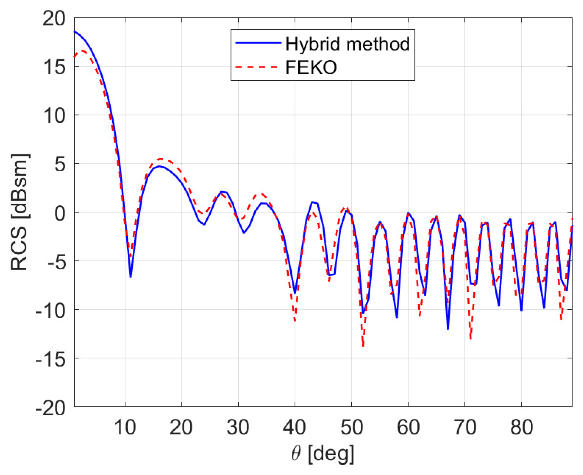
Moreover, in order to validate the use of the NFFF transformations for computing the secondary scattering contributions, the distance between the sphere (i.e., the FVTD region) and the plate (i.e., the asymptotic region) has been varied in the range D [ 1 ,   5 ]   m . The obtained results have been compared with those provided by the FEKO software (Altair Engineering Inc.) [44]. In particular, the hybrid solver based on the MoM and uniform theory of diffraction (UTD) has been applied considering a mesh of 708 triangular elements. The normalized root mean square error (NRMSE) between the RCS simulated by the proposed hybrid method and by the FEKO solver, for different values of the distance between plate and sphere, are reported in Table 1. Moreover, an example of the behavior of the RCS versus the elevation angle for the case D = 3   m is also shown in Figure 4. As can be seen, there is a good agreement between the proposed procedure and the results provided by FEKO. As expected, when the distance between FVTD region and asymptotic region is small, higher errors are present, since the far-field assumptions of the NFFF transformations are no longer satisfied.
As a further test, the sides of the plate have been varied between 0.5 and 2 m, with D = 4   m . In this case, the plate is discretized with N A S = 76 triangles. The errors on the computed RCS with respect to the results provided by FEKO are reported in Table 2. As expected, the error is lower when the plate is larger, mainly because the PO method is less effective in simulating the scattered field by small electrical objects.
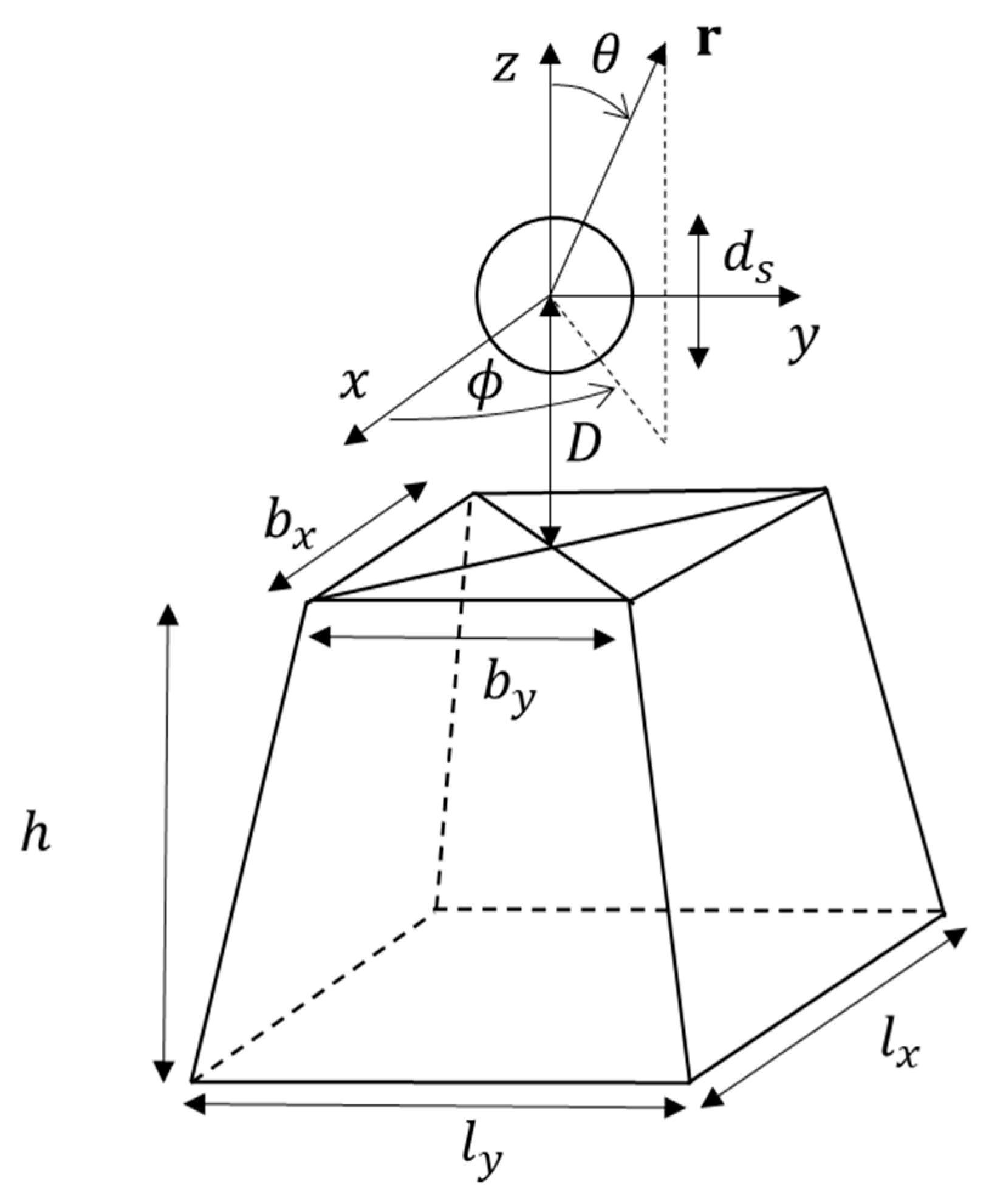
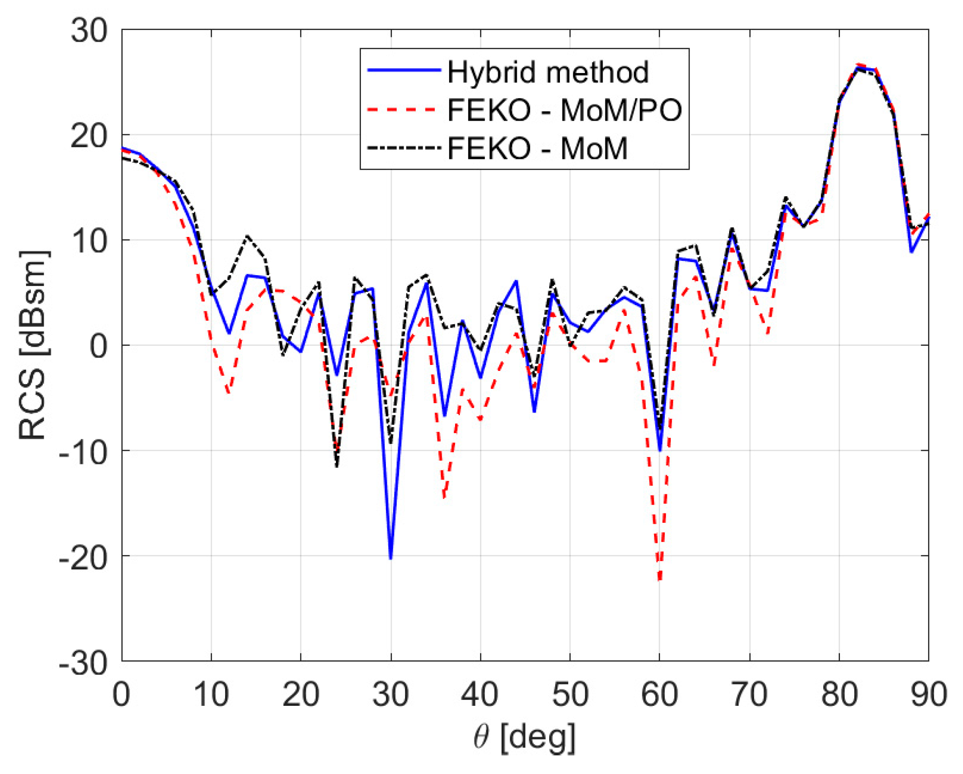
In the second considered test case, a PEC sphere of diameter d S = 0.318   m is located over a square frustum of height h = 2   m (Figure 5). The upper base has size b x = b y = 1   m , and the lower base has side lengths l x = l y = 1.5   m . The distance between the center of the sphere and the upper base of the frustum is equal to D = 3   m . The FVTD region is equal to the one considered in the previous case. The asymptotic region corresponds to the outer surface of the frustum, and it has been discretized with N A S = 158 triangles. Figure 6 shows the computed RCS at 750 MHz. The results given by the FEKO full MoM solver (with a mesh composed of 1360 triangular elements) are provided for comparison purposes, as well as FEKO results with hybrid MoM/PO solver with full ray tracing. As can be seen, the agreement between the proposed hybrid method and the full MoM solution, which has been taken as a reference, is quite good (the NRMSE is equal to 0.080), although for some directions the RCS is slightly underestimated. Such differences may be ascribed to the contributions of the field scattered by the asymptotic region and radiated onto the FVTD, which are currently neglected in the developed approach. It is also worth noting that, at least in this case, the obtained results are better than the ones of the FEKO MoM/PO approach, for which the NRMSE with respect to the full MoM is equal to 0.136.

4. Conclusions

In this paper, a hybrid approach based on the FVTD method and PO/ECM asymptotic techniques has been presented, with the aim of computing the scattered electromagnetic field by multi-scale objects. The computational domain is split into two parts: An FVTD region and an asymptotic region, which contain small-size and large structures, respectively. The mutual interactions between regions, which produce secondary scattered field contributions, are approximated by considering the most significant terms and far-field interactions. Preliminary numerical simulations, in which the proposed technique is compared with independent electromagnetic simulators for estimating the RCS of simple composite PEC targets, show the effectiveness of the approach. Future developments will be aimed at modeling near-field interactions between the two regions and at validating the technique in the presence of more complex structures and dielectric targets, for which the FVTD method is proven to be particularly effective. The combination of FVTD and asymptotic methods in the time-domain will be considered, too. Such an extension would allow simulations to take into account the contributions due to the field scattered by the asymptotic region and radiated back onto the FVTD region. Moreover, further work will also be devoted to the introduction of multiple reflections through the integration of geometrical optics techniques in order to increase the accuracy of the solution. Finally, the possibility of exploiting proper Green’s functions into the FVTD method for including the contributions of large structures, as well as the use of iterative schemes, will be explored.

Author Contributions

Conceptualization, A.F., M.P., and A.R.; methodology, A.F., M.P., and A.R.; formal analysis, A.F., M.P., and A.R.; investigation, A.F., M.P., and A.R.; validation, A.F., M.P., and A.R.

Funding

This research received no external funding.

Acknowledgments

The Authors are grateful to Riccardo Ferri for his support in the preparation of the numerical simulations reported in this paper.

Conflicts of Interest

The authors declare no conflict of interest.

References

  1. Rao, S.M. Time Domain Electromagnetics; Academic Press: San Diego, CA, USA, 1999; ISBN 978-0-08-051924-1. [Google Scholar]
  2. Davidson, D.B. Computational Electromagnetics for Rf and Microwave Engineering, 2nd ed.; Cambridge University Press: Cambridge, UK, 2010; ISBN 978-0-511-91890-2. [Google Scholar]
  3. Fumeaux, C.; Baumann, D.; Leuchtmann, P.; Vahldieck, R. A generalized local time-step scheme for efficient FVTD simulations in strongly inhomogeneous meshes. IEEE Trans. Microw. Theory Tech. 2004, 52, 1067–1076. [Google Scholar] [CrossRef]
  4. Frezza, F.; Pajewski, L.; Ponti, C.; Schettini, G. Through-wall electromagnetic scattering by N conducting cylinders. J. Opt. Soc. Am. A Opt. Image Sci. Vis. 2013, 30, 1632–1639. [Google Scholar] [CrossRef] [PubMed]
  5. Harrington, R.F. Field Computation by Moment Methods; IEEE: Piscataway, NJ, USA, 1993; ISBN 978-0-7803-1014-8. [Google Scholar]
  6. Taflove, A.; Hagness, S.C. Computational Electrodynamics: The Finite-Difference Time-Domain Method, 3rd ed.; Artech House: Boston, MA, USA, 2005; ISBN 1-58053-832-0. [Google Scholar]
  7. Ramahi, O.M.; Subramanian, V.; Archambeault, B. A simple finite-difference frequency-domain (FDFD) algorithm for analysis of switching noise in printed circuit boards and packages. IEEE Trans. Adv. Packag. 2003, 26, 191–198. [Google Scholar] [CrossRef]
  8. Clemens, M.; Weiland, T. Discrete electromagnetism with the finite integration technique. Prog. Electromagn. Res. 2001, 32, 65–87. [Google Scholar] [CrossRef]
  9. Paknys, R. Applied Frequency-Domain Electromagnetics; John Wiley & Sons: Hoboken, NJ, USA, 2016; ISBN 978-1-118-94054-9. [Google Scholar]
  10. Pregla, R.; Helfert, S. Analysis of Electromagnetic Fields and Waves: The Method of Lines; John Wiley & Sons: Hoboken, NJ, USA, 2008; ISBN 978-0-470-05850-3. [Google Scholar]
  11. Knott, E.F.; Shaeffer, J.; Tuley, M. Radar Cross Section, 2nd ed.; SciTech Publishing: Raleigh, NC, USA, 2004; ISBN 978-1-891121-25-8. [Google Scholar]
  12. Liu, Z.L.; Wang, X.; Wang, C.F. Installed performance modeling of complex antenna array mounted on extremely large-scale platform using fast MoM-PO hybrid framework. IEEE Trans. Antennas Propag. 2014, 62, 3852–3858. [Google Scholar] [CrossRef]
  13. Moneum, M.A.A.; Shen, Z.; Volakis, J.L.; Graham, O. Hybrid PO-MoM analysis of large axi-symmetric radomes. IEEE Trans. Antennas Propag. 2001, 49, 1657–1666. [Google Scholar] [CrossRef]
  14. Obelleiro, F.; Taboada, J.M.; Rodríguez, J.L.; Rubiños, J.O.; Arias, A.M. Hybrid moment-method physical-optics formulation for modeling the electromagnetic behavior of on-board antennas. Microw. Opt. Technol. Lett. 2000, 27, 88–93. [Google Scholar] [CrossRef]
  15. Çivi, Ö.A.; Pathak, P.H.; Chou, H.T.; Nepa, P. Hybrid uniform geometrical theory of diffraction—Moment method for efficient analysis of electromagnetic radiation/scattering from large finite planar arrays. Radio Sci. 2000, 35, 607–620. [Google Scholar] [CrossRef]
  16. Braaten, B.D.; Nelson, R.M.; Mohammed, M.A. Electric field integral equations for electromagnetic scattering problems with electrically small and electrically large regions. IEEE Trans. Antennas Propag. 2008, 56, 142–150. [Google Scholar] [CrossRef]
  17. Vipiana, F.; Francavilla, M.A.; Vecchi, G. EFIE modeling of high-definition multiscale structures. IEEE Trans. Antennas Propag. 2010, 58, 2362–2374. [Google Scholar] [CrossRef]
  18. Mei, X.; Zhang, Y.; Lin, H. A new efficient hybrid SBR/MoM technique for scattering analysis of complex large structures. In Proceedings of the 2015 IEEE International Conference on Computational Electromagnetics, Hong Kong, China, 2–5 February 2015; pp. 306–308. [Google Scholar]
  19. Chen, M.; Zhao, X.W.; Zhang, Y.; Liang, C.H. Analysis of antenna around nurbs surface with iterative MoM-PO technique. J. Electromagn. Waves Appl. 2006, 20, 1667–1680. [Google Scholar] [CrossRef]
  20. Liu, Z.L.; Wang, C.F. Efficient iterative method of moments-physical optics hybrid technique for electrically large objects. IEEE Trans. Antennas Propag. 2012, 60, 3520–3525. [Google Scholar] [CrossRef]
  21. Yang, L.X.; Ge, D.B.; Wei, B. FDTD/TDPO hybrid approach for analysis of the EM scattering of combinative objects. Prog. Electromagn. Res. 2007, 76, 275–284. [Google Scholar] [CrossRef]
  22. Faghihi, F.; Heydari, H. Time domain physical optics for the higher-order FDTD modeling in electromagnetic scattering from 3-D complex and combined multiple materials objects. Prog. Electromagn. Res. 2009, 95, 87–102. [Google Scholar] [CrossRef]
  23. Chia, T.T.; Burkholder, R.J.; Lee, R. The application of FDTD in hybrid methods for cavity scattering analysis. IEEE Trans. Antennas Propag. 1995, 43, 1082–1090. [Google Scholar] [CrossRef]
  24. Lepvrier, B.L.; Loison, R.; Gillard, R.; Pouliguen, P.; Potier, P.; Patier, L. A new hybrid method for the analysis of surrounded antennas mounted on large platforms. IEEE Trans. Antennas Propag. 2014, 62, 2388–2397. [Google Scholar]
  25. Chou, H.T.; Hsu, H.T. Hybridization of simulation codes based on numerical high and low frequency techniques for the efficient antenna design in the presence of electrically large and complex structures. Prog. Electromagn. Res. 2008, 78, 173–187. [Google Scholar] [CrossRef]
  26. Burkholder, R.J.; Kim, Y.; Pathak, P.H.; Lee, J.F. Green’s function approach for interfacing UTD with FEM for a conformal array antenna on a large platform. In Proceedings of the Fourth European Conference on Antennas and Propagation, Barcelona, Spain, 12–16 April 2010; pp. 1–4. [Google Scholar]
  27. Burkholder, R.J.; Pathak, P.H.; Sertel, K.; Marhefka, R.J.; Volakis, J.L.; Kindt, R.W. A hybrid framework for antenna/platform analysis. ACES J. 2006, 21, 177–195. [Google Scholar]
  28. Tzoulis, A.; Eibert, T.F. A hybrid FEBI-MLFMM-UTD method for numerical solutions of electromagnetic problems including arbitrarily shaped and electrically large objects. IEEE Trans. Antennas Propag. 2005, 53, 3358–3366. [Google Scholar] [CrossRef]
  29. Yee, K.S.; Chen, J.S. The finite-difference time-domain (FDTD) and the finite-volume time-domain (FVTD) methods in solving Maxwell’s equations. IEEE Trans. Antennas Propag. 1997, 45, 354–363. [Google Scholar] [CrossRef]
  30. Bonnet, P.; Ferrieres, X.; Issac, F.; Paladian, F.; Grando, J.; Alliot, J.C.; Fontaine, J. Numerical Modeling of Scattering Problems Using a Time Domain Finite Volume Method. J. Electromagn. Waves Appl. 1997, 11, 1165–1189. [Google Scholar] [CrossRef]
  31. Baumann, D.; Fumeaux, C.; Vahldieck, R. Field-based scattering-matrix extraction scheme for the FVTD method exploiting a flux-splitting algorithm. IEEE Trans. Microw. Theory Tech. 2005, 53, 3595–3605. [Google Scholar] [CrossRef]
  32. Fumeaux, C.; Baumann, D.; Vahldieck, R. Finite-volume time-domain analysis of a cavity-backed Archimedean spiral antenna. IEEE Trans. Antennas Propag. 2006, 54, 844–851. [Google Scholar] [CrossRef]
  33. Baumann, D.; Fumeaux, C.; Hafner, C.; Li, E.P. A modular implementation of dispersive materials for time-domain simulations with application to gold nanospheres at optical frequencies. Opt. Express 2009, 17, 15186–15200. [Google Scholar] [CrossRef] [PubMed]
  34. Bozza, G.; Caviglia, D.D.; Ghelardoni, L.; Pastorino, M. Cell-centered finite-volume time-domain method for conducting media. IEEE Microw. Wirel. Compon. Lett. 2010, 20, 477–479. [Google Scholar] [CrossRef]
  35. Almpanis, G.; Fumeaux, C.; Vahldieck, R. The trapezoidal dielectric resonator antenna. IEEE Trans. Antennas Propag. 2008, 56, 2810–2816. [Google Scholar] [CrossRef]
  36. Yee, K.S.; Chen, J.S. Conformal hybrid finite difference time domain and finite volume time domain. IEEE Trans. Antennas Propag. 1994, 42, 1450–1455. [Google Scholar] [CrossRef]
  37. Ferrieres, X.; Parmantier, J.P.; Bertuol, S.; Ruddle, A.R. Application of a hybrid finite difference/finite volume method to solve an automotive EMC problem. IEEE Trans. Electromagn. Compat. 2004, 46, 624–634. [Google Scholar] [CrossRef]
  38. Chatterjee, A.; Myong, R.S. Efficient implementation of higher-order finite volume time-domain method for electrically large scatterers. Prog. Electromagn. Res. 2009, 17, 233–254. [Google Scholar] [CrossRef]
  39. Cerruti, M.; Pastorino, M.; Randazzo, A. A hybrid FVTD-PO approach for the characterization of antennas on large platforms in naval applications. In Proceedings of the 2015 MTS IEEE OCEANS, Genoa, Italy, 8–21 May 2015; pp. 1–5. [Google Scholar]
  40. Lax, P.; Wendroff, B. Systems of conservation laws. Commun. Pure Appl. Math. 1960, 13, 217–237. [Google Scholar] [CrossRef]
  41. Domingo, M.; Torres, R.P.; Catedra, M.F. Calculation of the RCS from the interaction of edges and facets. IEEE Trans. Antennas Propag. 1994, 42, 885–888. [Google Scholar] [CrossRef]
  42. Balanis, C.A. Advanced Engineering Electromagnetics, 2nd ed.; John Wiley & Sons: Hoboken, NJ, USA, 2012; ISBN 978-0-470-58948-9. [Google Scholar]
  43. Ufimtsev, P.Y. Fundamentals of the Physical Theory of Diffraction; IEEE: Hoboken, NJ, USA, 2007; ISBN 978-0-470-09771-7. [Google Scholar]
  44. Electromagnetic Simulation Software|Altair FEKO. Available online: https://altairhyperworks.com/product/FEKO (accessed on 17 November 2019).
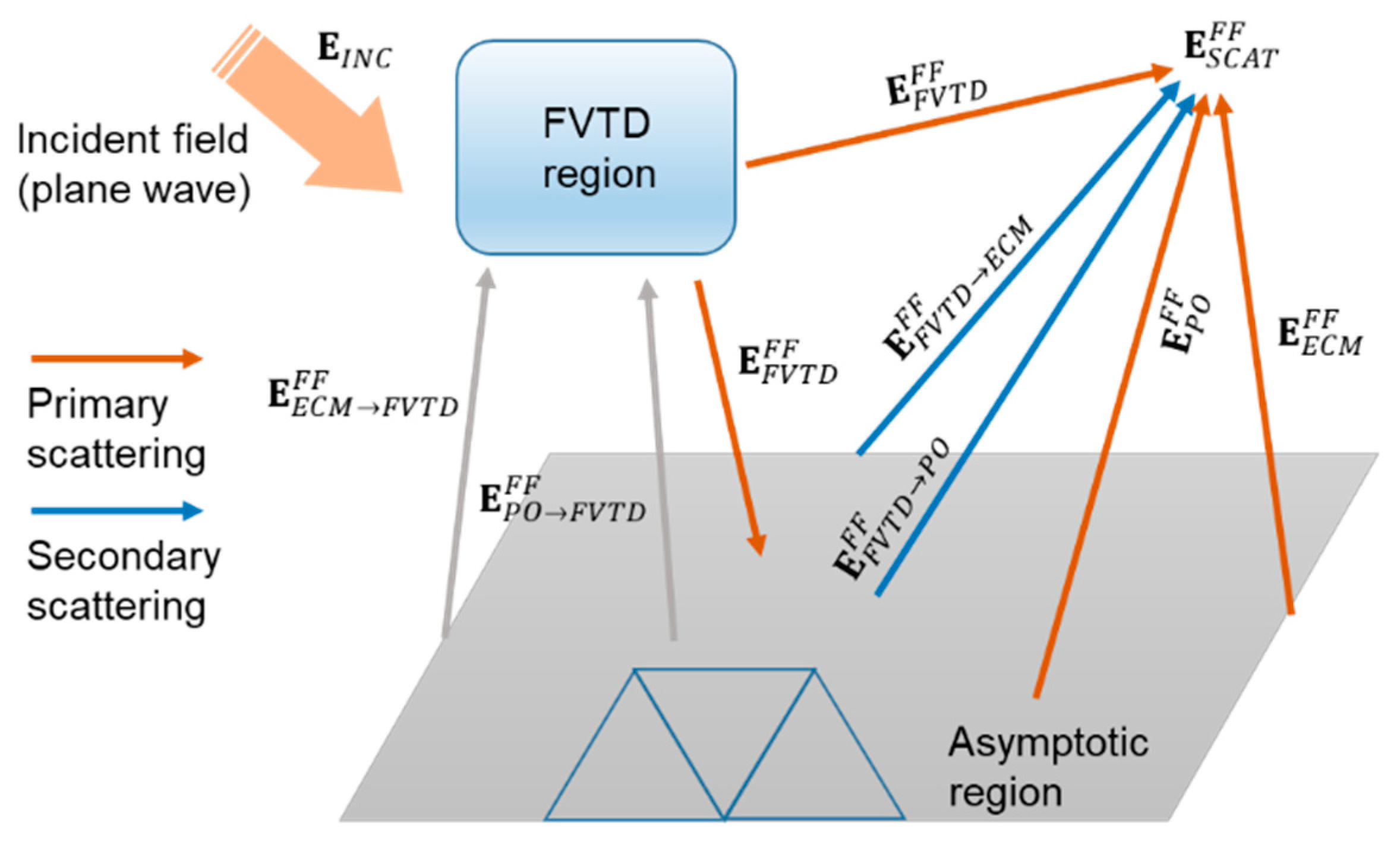
Figure 1. Combined contributions of the two regions.
Electronics 08 01388 g001
Figure 2. Schematic representation of the first configuration. Sphere over a perfect electric conducting (PEC) plate.
Electronics 08 01388 g002
Figure 3. Radar cross section (RCS) of the sphere over plate target. Plate of sides l x = l y = 1   m located at D = 5   m from the sphere. Comparison with the RCS of the sphere and plate alone.
Electronics 08 01388 g003
Figure 4. RCS of the sphere over plate target. Plate of sides l x = l y = 1   m located at D = 3   m from the sphere. Comparison with the results provided by the FEKO software.
Electronics 08 01388 g004
Figure 5. Schematic representation of the second configuration. Sphere over a PEC square frustum.
Electronics 08 01388 g005
Figure 6. RCS of the sphere over frustum target. Comparison with the results provided by the FEKO software (full method of moments (MoM) and MoM/physical optics (PO) approaches).
Electronics 08 01388 g006
Table 1. Normalized root mean square error (NRMSE) versus the distance between asymptotic and Finite Volume Time-Domain (FVTD) regions.
Distance [m]12345
NRMSE0.1180.0720.0550.0560.056
Table 2. Normalized root mean square error (NRMSE) versus the size of the plate.
Plate side [m]0.512
NRMSE0.1420.0560.048