Article

Focusing Arc-Array Bistatic Synthetic Aperture Radar Data Based on Keystone Transform

1
College of Information Engineering, Inner Mongolia University of Technology, Hohhot 010051, China
2
Inner Mongolia Key Laboratory of Radar Technology and Application, Hohhot 010051, China
3
National Lab of Radar Signal Processing, Xi’an 710000, China
*
Authors to whom correspondence should be addressed.
Electronics 2019, 8(12), 1389; https://doi.org/10.3390/electronics8121389
Submission received: 13 October 2019 / Revised: 10 November 2019 / Accepted: 19 November 2019 / Published: 21 November 2019
(This article belongs to the Section Microwave and Wireless Communications)

Abstract

:
Arc-array synthetic aperture radar (AA-SAR) has become a novel imaging scheme for full azimuth observation. However, the exiting arc-array monostatic SAR system is placed on a single platform and is easy to detect. Arc-array bistatic SAR (AA-BiSAR) with a stationary transmitter is proposed in this paper, which can obtain high data acquisition efficiency and reduce vulnerability of arc-array monostatic SAR. Furthermore, since the azimuth resolution with full azimuth observation is not related to the location of the stationary transmitter, the transmitter can be placed far away from the receiver. Compared with imaging algorithms for other modes, the key points of AA-BiSAR imaging algorithms are a square root in the bistatic slant range equation and an arc synthetic array in azimuth. According to the imaging geometry of AA-BiSAR, a novel imaging approach for AA-BiSAR based on keystone transform (KT) is proposed, and the KT implements range-cell migration correction (RCMC) in conditions of trigonometric function under square root in the range history and arc synthetic array in azimuth via reformatting the AA-BiSAR raw data. Besides presenting the proposed imaging approach, a complete resolution analysis of AA-BiSAR is given. Results of numerical simulation experiments on point targets validate the proposed imaging approach.

1. Introduction

A synthetic aperture radar (SAR) has all-weather, all-day, high-resolution and multi-dimensional imaging capabilities [1,2,3,4,5,6,7]. The traditional linear array SAR (LA-SAR) [8,9,10,11] can only observe the front area of the antenna array unit from a single angle of view. Compared with LA-SAR, arc-array SAR (AA-SAR) [12,13,14,15,16,17,18,19,20,21] is a novel array microwave imaging mode with full azimuth observation, which breaks through the limitation of the single observation angle of conventional LA-SAR. Furthermore, AA-SAR can realize quickly high-resolution imaging in area around the imaging platform. Therefore, rapid perception and dynamic monitoring of the surrounding environment can be easily achieved in AA-SAR. However, the receiver and the transmitter of conventional arc-array monostatic SAR are placed on the same platform, which is easy to detect, and this will affect abilities of target detection and recognition especially for military applications.
Bistatic SAR (BiSAR) attracted widespread interest, and it has become an important means of target detection and surface surveillance in recent years [22,23,24,25,26,27,28]. BiSAR inherits the advantages of SAR, and the transmitter and the receiver are separated, which is seen as an effective means of countering the vulnerability of conventional monostatic SAR. On this basis, an arc-array bistatic SAR (AA-BiSAR) with a stationary transmitter is proposed in this paper. AA-BiSAR has advantages of both BiSAR and AA-SAR, which could obtain highly efficient data acquisition and reduce the vulnerability of arc-array monostatic SAR. In AA-BiSAR, high-range resolution can be achieved by the high-power wide-bandwidth linear frequency modulation (LFM) signal transmitted by the stationary transmitter far away from the passive receiver, while in the azimuth direction, multiple antenna array elements are arranged along a cylinder to form an arc-synthetic aperture, the switched array antenna channels scan quickly over circular aperture. Therefore, high resolution, high-speed and wide view angle data acquisition is realized. Since the transmitter is mounted on a stationary platform or a low-speed platform in the AA-BiSAR system, a moving passive receiver platform is the only factor to be considered when solving problems for instance motion compensation and parameter estimation [29,30,31,32,33]. Furthermore, as the variation of the transmitting slant range does not or hardly impacts on the azimuth resolution, AA-BiSAR can be used in the fields of emergency landing, self-landing, air-drop supplies, terminal guidance, moving target indication etc. Moreover, due to the receiver and the transmitter being fixed on different platforms, this imaging scheme can avoid physical attack to the imaging platform and reduce the vulnerability for military applications.
For SAR imaging, range-cell migration (RCM) [34] is an inherent and key problem for all kinds of SAR systems with a high-resolution, and SAR imaging ability is greatly affected by the performance of RCM correction (RCMC). In this paper, a novel imaging approach for AA-BiSAR based on keystone transform (KT) is proposed. KT is a kind of data scale remapping method, which is usually applied to a target’s range migration correction [35,36,37,38,39]. In the LA-SAR system, it can correct the walk of the target cross range unit by eliminating the coupling term of the elements of range direction and azimuth direction. Nonetheless, since there are both of the angle element of the azimuth and the trigonometric function in the slant range equation in AA-BiSAR, the transform is a non-linear transform, rather than a simply linear reformatting. In AA-BiSAR, the KT implements RCMC under conditions of trigonometric function under square root in the slant range history and arc synthetic array in azimuth via reformatting the AA-BiSAR raw data.
This paper is arranged as follows. In Section 2, the basic principle and imaging geometry of AA-BiSAR imaging is introduced, while the echo signal model based on the imaging geometry is established. In Section 3, the proposed processing method of AA-BiSAR imaging based on KT is presented. In Section 4, the spatial resolution of AA-BiSAR is analyzed. In Section 5, numerical simulation experiments on point targets are carried out, and imaging results of point targets validate the proposed imaging approach. Finally, conclusions are reported in Section 6.

2. Arc-Array Bistatic Synthetic Aperture Radar (SAR) System

As shown in Figure 1a, the passive arc-array receiving antenna system contains three major parts: the arc antenna array, the microwave switch network, and the data-receiving model. The high-speed microwave switch network is used to select the different independent elements of the passive arc-array antenna and control the reception. The data receiving center is used to receive the electromagnetic signal at the same time to complete the process of data acquisition. A passive arc-array antenna is an important part of AA-BiSAR, and it relates to whether the whole imaging system can achieve full azimuth imaging quickly. The structure of the passive arc-receiving antenna array is shown in Figure 1b, where “AB” represents the passive receiving antenna elements. As we can see from Figure 1b, multiple antenna array elements are arranged along the part of cylinder, the angle interval between adjacent antenna elements is set to Δ θ Interval , and the radius of the arc-array antenna is R r . θ s stands for the synthetic aperture angle of the arc antenna array, θ a represents the azimuth beam width of the antenna array element along the arc antenna array direction, while the effective azimuth direction observation area of the system is determined by the size of θ s and θ a . N r is the number of antenna array elements used to form an arc synthetic aperture angle. By contrast with the mechanical movement of traditional LA-SAR systems, the electronic scanning mode of the passive arc-array antenna in AA-BiSAR has significant advantages such as instantaneous data acquisition, large-angle view imaging, and azimuth direction stable sampling positions etc. Furthermore, it is worth to noting that the arc configuration adopts rigid baseline structure, on the one hand it avoids the influence of helicopter fuselage shaking on the antenna, on the other, it is conducive to the realization of the system [12,13,14].
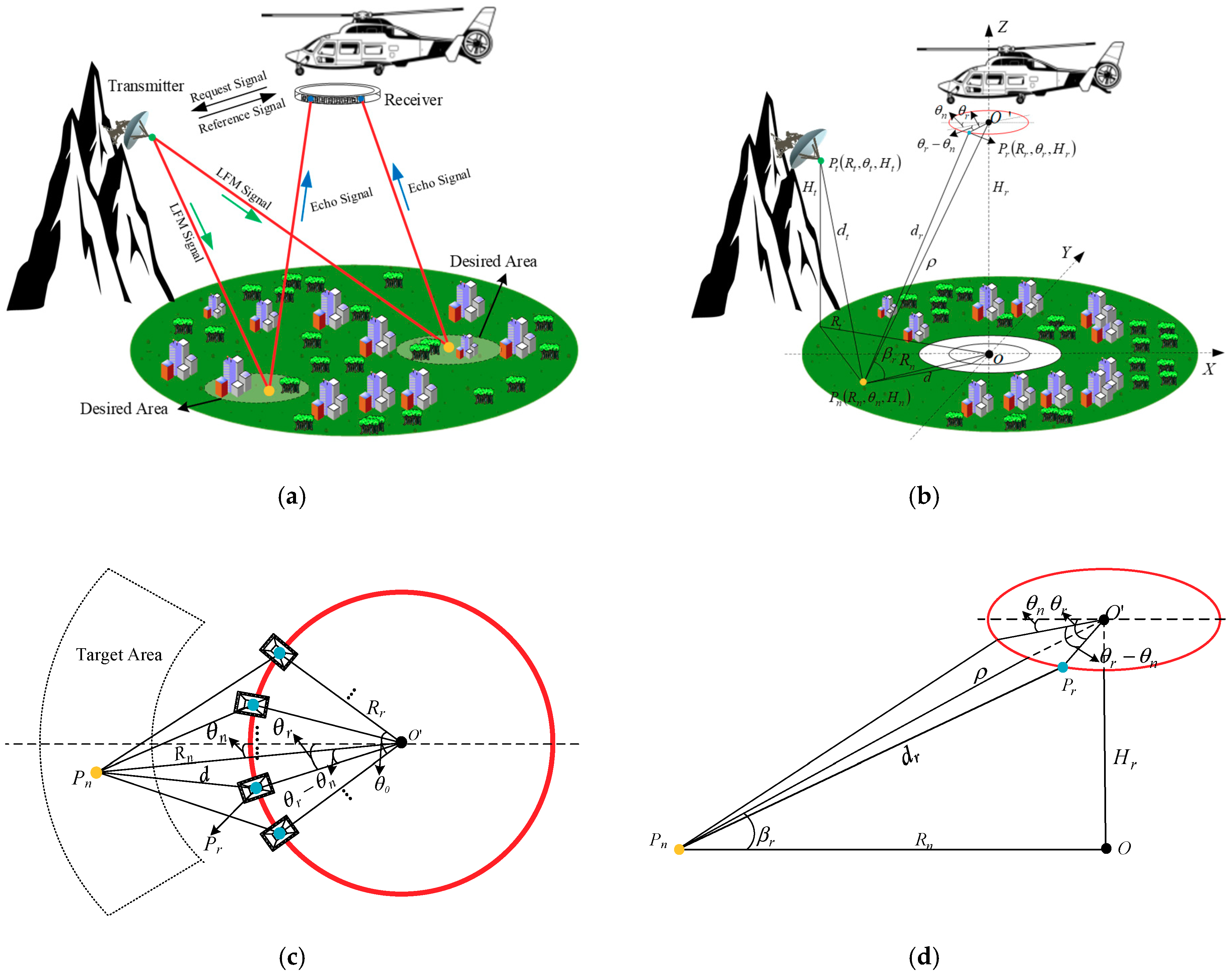
The imaging principle of AA-BiSAR is simplified as shown in Figure 2a. The helicopter platform receiver sends a request signal to the transmitting platform, then the transmitter emits high-power LFM signal to the desired area, and next, the passive receiving arc antenna array uses high-speed microwave switch network control the reception of echo signal. The echo signal from one target can be received by multiple antenna elements. Due to the special circular structure of the arc-array antenna, for those targets that are at the same distance, the number of the reception antenna elements is the same. The transmitter can be fixed on the mountain far from the desired scene, which reduced its vulnerability to physical attack. The receiver is mounted on the belly of the helicopter platform, which can be completely passive so it does not advertise its position by radio frequency emissions. Meanwhile, the bistatic synchronization is achieved by using the continuous transfer of time and frequency standards between two platforms.
The imaging geometry of the AA-BiSAR is shown in Figure 2b, the top view and the side view of the imaging geometry are shown in Figure 2c,d, respectively O . As we can see from the figure of the imaging geometry, O is the center of the passive arc-array antenna, is the origin of coordinate. The instantaneous slant range distance between P r and P n is given as d r , d t is referred to the instantaneous slant range distance from the transmitter antenna to the target. d denotes the projection of d r at X O Y plane, ρ is the distance between P n and arc-array antenna center O , β r represents the angle between the arc-array antenna plane and O P n , which can be calculated by cos β r = ρ 2 H t 2 / ρ . P r ( R r , θ r , H r ) stands for the polar coordinate of equivalent sampling point P r at arc-array antenna, P n ( R n , θ n , H n ) stands for the position of the point target P n , and the transmitter’s position is located at P t ( R t , θ t , H t ) .
For the position of equivalent sampling point P r ( R r , θ r , H r ) , R r stands for the radius of the arc-array antenna, θ r denotes the azimuth direction angle of P r , H r stands for the height of the arc-array antenna.
For the position of point target P n ( R n , θ n , H n ) , R n is referred to the distance from P n to the origin of coordinate O , θ n represents the azimuth direction angle of P n , H n stands for the height of P n .
For the position of transmitter P t ( R t , θ t , H t ) , θ n represents the angle of P t in polar coordinates. R t is referred to the ground distance from P t to O , H t is the height of P t

3. Imaging Algorithm Based on Keystone Transform

3.1. Signal Model

The transmitted chirp signal is as follows:
p ( τ ) = rect ( τ T r ) exp ( j 2 π f c τ + j π k τ 2 )
where rect ( τ / T r ) represents the rectangular envelope with the duration T r , k is referred to as the frequency modulation rate, the carrier frequency is shown as f c , and τ is the range time.
After demodulation to baseband, the signal reflected from the target P n to the equivalent sampling point P r can be calculated in terms of the range time τ and the azimuth angel θ r as:
s ( τ , θ r ; R n , θ n ) = σ n ( R n , θ n , H n ) rect [ θ r θ n θ a ] rect [ τ R ( θ r ; R n , θ n ) / c T r ] exp { j 2 π f c c R ( θ r ; R n , θ n ) } exp { j π k [ τ R ( θ r ; R n , θ n ) c ] 2 }
where σ n ( R n , θ n , H n ) stands for the reflectivity of the point target P n , θ a is the beam width in azimuth, rect [ ( θ r θ n ) / θ a ] represents the envelope with θ a , and c is the speed of light. According to the imaging geometry shown in Figure 2b, the bistatic slant range R ( θ r ; R n , θ n ) can be written as:
{ R ( θ r ; R n , θ n ) = d t ( R n , θ n ) + d r ( θ r ; R n , θ n ) d t ( R n , θ n ) = ( R t cos θ t R n cos θ n ) 2 + ( R t sin θ t R n sin θ n ) 2 + ( H t H n ) 2 d r ( θ r ; R n , θ n ) = ( R r cos θ r R n cos θ n ) 2 + ( R r sin θ r R n sin θ n ) 2 + ( H r H n ) 2 θ r = Δ θ interval × m , m = 1 , 2 , 3 , , N r
Echoes of the whole observation scene can be generally written as:
s ( τ , θ r ; R n , θ n ) = { σ n ( R n , θ n , H n ) rect [ θ r θ n θ a ] rect [ τ R ( θ r ; R n , θ n ) / c T r ] exp { j 2 π f 0 c R ( θ r ; R n , θ n ) } exp { j π k [ τ R ( θ r ; R n , θ n ) c ] 2 } }

3.2. Range Process and Keystone Transform

The signal in Equation (2) is transformed into the range frequency domain via the principle of stationary phase (POSP), and the result can be computed as follows:
S r f ( f τ , θ r ; R n , θ n ) = FFT [ s ( τ , θ r ; R n , θ n ) ] = s ( τ , θ r ; R n , θ n ) exp ( j 2 π f τ ) d τ = σ n ( R n , θ n , H n ) rect ( θ r θ n θ a ) rect ( f τ k T r ) exp [ j 2 π ( f c + f τ ) c R ( θ r ; R n , θ n ) ] exp ( j π f τ 2 k )
where FFT [ ] represents fast Fourier transform operation. After range compression, Equation (5) can be expressed as:
S s f _ c ( f τ , θ r ; R n , θ n ) = S s f ( f τ ) H r ( f τ ) = σ n ( R n , θ n , H n ) rect ( θ r θ n θ a ) rect ( f τ k T r ) exp [ j 2 π ( f c + f τ ) c R ( θ r ; R n , θ n ) ]
where H r ( f τ ) stands for the range matched filtering function, and can be described as:
H r ( f τ ) = rect ( f τ k T r ) exp ( j π f τ 2 k )
If Equation (6) is applied with range-inverse fast Fourier transform:
s s f _ c ( τ , θ r ; R n , θ n ) = IFFT [ S s f _ c ( f τ ) ] = S s f _ c ( f τ ) exp ( j 2 π f τ τ ) d f τ = σ n ( R n , θ n , H n ) rect ( θ r θ n θ a ) p r ( τ R ( θ r ; R n , θ n ) c ) exp ( j 2 π f c c R ( θ r ; R n , θ n ) )
where IFFT [ ] represents the inverse fast Fourier transform operation, p r { t [ R ( θ r ; R n , θ n ) / c ] } is the inverse Fourier transform of rect ( f τ / k T r ) , be represented as a sinc-type envelope, which contains the target range migration R ( θ r ; R n , θ n ) / c . From Equation (8), we can see that R ( θ r ; R n , θ n ) related to the azimuth direction element cause the envelope of the range to vary.
Afterwards, the Equation (3) can be written as:
R ( θ r ; R n , θ n ) = d t ( R n , θ n ) + d r ( θ r ; R n , θ n ) = d t ( R n , θ n ) + ρ 2 + R r 2 2 ρ R r cos β r cos ( θ r θ n )
Since the arc-array radius is R r < < ρ , and R ( θ r ; R n , θ n ) can be approximated as:
R ( θ r ; R n , θ n ) d t ( R n , θ n ) + ρ R r cos β r cos ( θ r θ n )
Substituting Equation (10) into Equation (6):
S r f _ c ( f τ , θ r ; R n , θ n ) = σ n ( R n , θ n , H n ) rect ( θ r θ n θ a ) rect ( f τ k T r ) exp { j 2 π ( f c + f τ ) c [ d t ( R n , θ n ) + ρ R r cos β r cos ( θ r θ n ) ] }
For facilitate the analysis, Equation (11) is reorganized as:
S r f _ c ( f τ , θ r ; R n , θ n ) = σ n ( R n , θ n , H n ) rect ( θ r θ n θ a ) rect ( f τ k T r ) exp [ j 2 π ( f c + f τ ) c [ d t ( R n , θ n ) + ρ ] ] exp [ j 2 π f c c R r cos β r cos ( θ r θ n ) ] exp [ j 2 π c R r f τ cos β r cos ( θ r θ n ) ]
With reference to Equation (12), it can be observed that the range frequency variable f τ couples with the azimuth variable element θ r in the third index term, which is the main cause of the range envelope movement. The couple eliminating must be carried before the azimuth focusing step.
The keystone transform decouples f τ and θ r by reformatting the axis as Equation (13), and the angle φ is a redefined virtual azimuth direction sampling:
cos ( φ θ n ) = f c + f τ f c cos ( θ r θ n )
Since this transform contains trigonometric functions, its uniqueness must be ensured. As is shown in Figure 2c, multiple antenna array elements are arranged along the part of circular to form an arc synthetic aperture in the AA-BiSAR system. The aperture angle of array synthesis θ s mainly affected by the geometric relationship between the target and the array, then θ s can be about less or equal to the azimuth beam width θ a , that is, θ s θ a . In general, θ s is about equal to θ a to obtain better azimuth direction resolution [14]. Due to the electronic scanning mode, the high-speed microwave switch network can select and control on/off of the antenna array elements according to the target’s position. Consequently, the variation range of ( θ r θ n ) is less than or equal to the half array beam width θ a / 2 , and θ a / 2 is generally less than 90°. As cos ( θ r θ n ) is a monotonous function with the angle range of 0°~90°, the uniqueness of this transform can be ensured. Substituting Equation (13) into Equation (11):
S r f _ c k ( f τ , φ ; R n , θ n ) = σ n ( R n , θ n , H n ) rect ( φ θ n θ a ) rect ( f τ k T r ) exp { j 2 π f c c [ d t ( R n , θ n ) + ρ R r cos β r cos ( φ θ n ) ] } exp { j 2 π f τ c [ d t ( R n , θ n ) + ρ ] }
and when range inverse Fourier transform is applied, we then obtain:
s r _ k ( τ , φ ; R n , θ n ) = IFFT [ S r f _ c k ( f τ ) ] = S r f _ c k ( f τ ) exp ( j 2 π f τ τ ) d f τ = σ n ( R n , θ n , H n ) rect ( φ θ n θ a ) p r [ τ d t ( R n , θ n ) + ρ c ] exp { j 2 π f c c [ d t ( R n , θ n ) + ρ ] } exp [ j 2 π f c c R r cos β r cos ( φ θ n ) ]
The echo signal after the range movement correction is presented in Equation (15). It can be seen that the coupling term is eliminated via keystone transform. The range envelope does not vary with the azimuth element any more, and echoes of different range units are corrected to the same range unit.

3.3. Azimuth Process

The azimuth-matched filtering process need to be carried out in the range frequency domain, so an azimuth Fourier transform is applied on Equation (15). In the imaging approach proposed, the azimuth-matched filter can be achieved by the fast convolution which contains conjugate operation and FFT operation. The kernel function for the convolution is calculated as:
h a ( φ ) = exp [ j 2 π f c c R r cos β r cos ( φ θ n ) ]
The azimuth-matched filtering function is calculated as:
H a ( f φ ) = { FFT [ h a ( φ ) ] } *
where [ ] * is referred to the complex conjugate operation. After the azimuth matched filtering and azimuth inverse fast Fourier transform operation, the signal is compressed as:
s r _ k a ( τ ; R n , θ n ) = σ n ( R n , θ n , H n ) p a ( φ θ n ) p r [ τ d t ( R n , θ n ) c ] exp [ j 2 π f c c [ d t ( R n , θ n ) + ρ ] ]
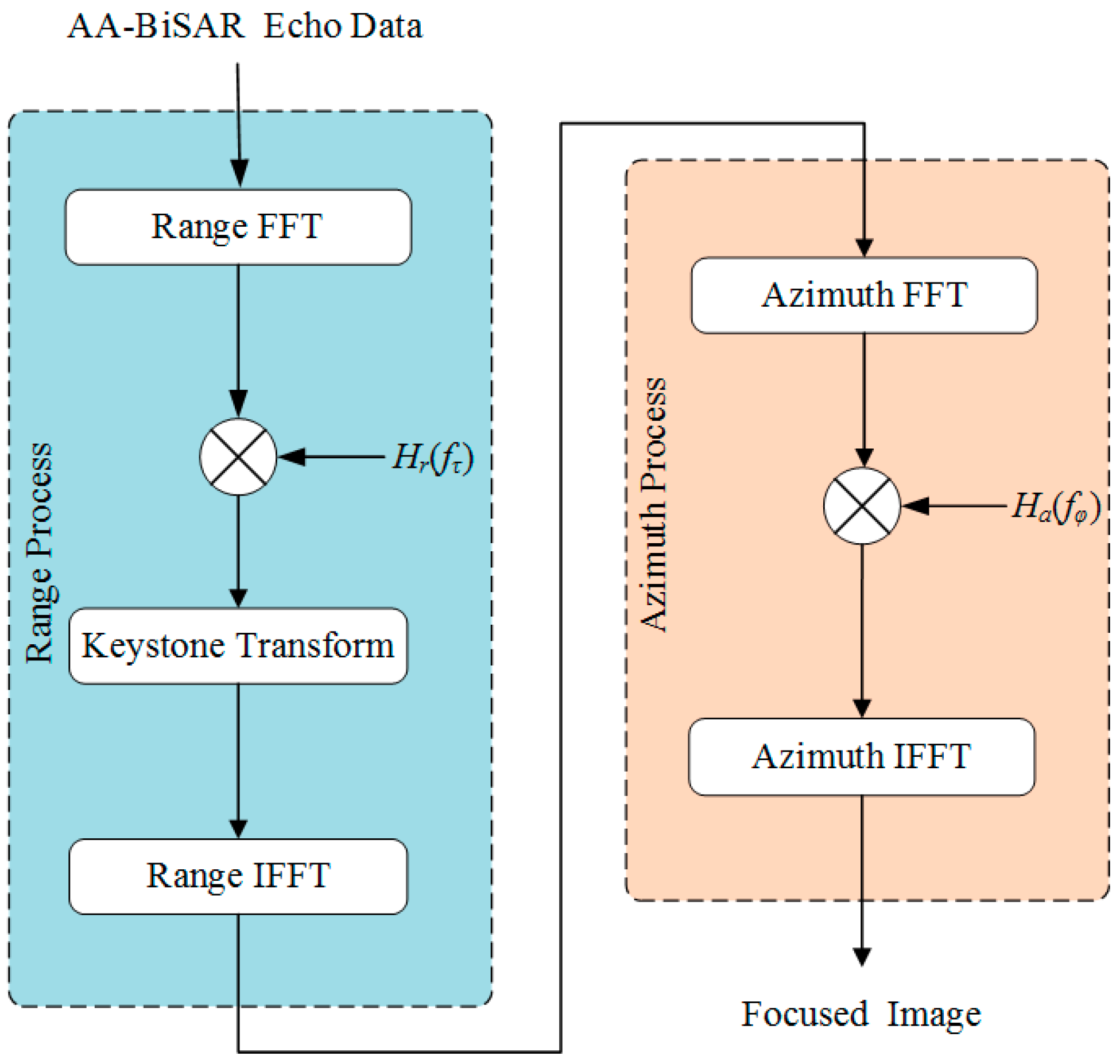
where p a ( φ θ n ) is the envelope in the azimuth direction. The proposed imaging approach can be summarized as shown in Figure 3. Since the acquired echo data is stored in a polar coordinate system, it can be converted into Cartesian coordinate through following formula:
{ x t = R t sin θ t , y t = R t cos θ t , z t = H t x r = R r sin θ r , y r = R r cos θ r , z r = H r x n = R n sin θ n , y n = R n cos θ n , z n = H n
where ( x n , y n , z n ) is the position of target in the Cartesian coordinate system, ( x t , y t , z t ) is the position of the transmitter in the Cartesian coordinate system, ( x r , y r , z r ) is the position of the receiver in the Cartesian coordinate system.

4. Resolution Analysis

4.1. Azimuth Angular Resolution

Different from other SAR modes, the azimuth resolution along arc antenna array direction in AA-BiSAR, also called azimuth angular resolution or array angular resolution (unit is degree) [14,15,16,17,18,19,20,21], is achieved by an arc synthetic aperture formed with several antenna elements and echo signal coherent integration. As shown in Figure 1b, due to the structure of the receive arc-array antenna of AA-BiSAR, the instantaneous azimuth frequency f θ is always perpendicular to the radius of the arc-array antenna. That is, the direction of f θ changes with the sampling position. Therefore, according to Equations (8) and (10), the instantaneous azimuth frequency f θ is:
f θ = θ r { arg [ S s f _ c ( τ , θ r ; R n , θ n ) ] } = 2 π R r cos β r sin ( θ r θ n ) λ
where arg [ ] represents the argument operation. As we have discussed in Section 3.2, the variation range of ( θ r θ n ) is less than or equal to the half azimuth beam width θ a / 2 , and θ a / 2 is generally less than 90°. In general, f θ is a monotonous function with the angle range of 0°~90°. As a result, the azimuth angular resolution of the AA-BiSAR can be approximate calculated as:
ρ θ = 2 π max { f θ } min { f θ } λ 2 R r sin ( θ a / 2 ) cos β r
As it can be seen from Figure 2b,d, β r represents the angle between the arc-array antenna plane and O P n , and can be calculated by cos β r = ρ 2 H t 2 / ρ . Then Equation (21) can be expressed as:
ρ θ = λ 2 R r sin ( θ s / 2 ) ρ ρ 2 H r 2 = λ 2 R r sin ( θ s / 2 ) ρ R n
where λ is wavelength of the signal, θ s is the aperture angle of array synthesis, θ s θ a . With reference to Equation (22), the azimuth angular resolution of AA-BiSAR is related to radius of the arc-array antenna, the synthesis aperture angle of array and the height of platform. Furthermore, it not varies with bistatic slant range distance, but related to the ground distance from target to the arc-array antenna. The azimuth angular resolution of different point targets is shown in Figure 4a, it can be seen that, the azimuth angular resolution of AA-BiSAR is independent of the azimuth angle of each target and whether it is at the beam edge, and for those targets that are at the same distance, the azimuth angular resolution stays the same.

4.2. Ground-Range Resolution

In AA-BiSAR, as the receiving platform and transmitting platform are fixed at two separate places, the instantaneous bistatic slant range contains distances in two different directions, and the projection of the slant range at the ground range will not derived by simple linear transformation [40,41,42,43]. Therefore, since the physical meaning of “range direction” in AA-BiSAR cannot clearly be defined, the resolution ability of AA-BiSAR on the ground cannot be simply described with bistatic-range resolution. Thus, the slant range resolution of AA-BiSAR is more complex and difficult than that of traditional monostatic SAR. Thus, the ground-range resolution of AA-BiSAR is considered directly in this paper.
The geometry of AA-BiSAR is shown in Figure 2b, the transmitter and receiver are located at ( R t , θ t , H t ) and ( R r , θ r , H r ) , respectively, while the target point’s position is ( R n , θ n , H n ) . According to Equations (3) and (19), for an arbitrary point ( x n , y n ) at ground plane, the instantaneous bistatic slant range R can be calculated as:
R = ( x n x t ) 2 + ( y n y t ) 2 + z t 2 + ( x n x r ) 2 + ( y n y r ) 2 + z r 2
The gradient of the instantaneous bistatic slant range in AA-BiSAR can be expressed as:
R = ( sin ξ t cos ϕ t + sin ξ r cos ϕ r ) i x + ( sin ϕ t + sin ϕ r ) i y
Then, the magnitude of R can be present as:
| R | = ( sin ξ t cos ϕ t + sin ξ r cos ϕ r ) 2 + ( sin ϕ t + sin ϕ r ) 2
where ξ t , ξ r , ϕ t and ϕ r are, respectively, expressed as:
ξ t = arcsin [ x n x t ( x n x t ) 2 + z t 2 ]
ξ r = arcsin [ x n x r ( x n x r ) 2 + z r 2 ]
ϕ t = arcsin ( y n y t ( x n x t ) 2 + ( y n y t ) 2 + z t 2 )
ϕ r = arcsin ( y n y r ( x n x r ) 2 + ( y n y r ) 2 + z r 2 )
As the resolution magnitude of the AA-BiSAR bistatic slant range is c / B r , the ground range resolution of AA-BiSAR at ( x n , y n ) can be derived as:
ρ r = c / B r | R | = c / B r ( sin ξ t cos ϕ t + sin ξ r cos ϕ r ) 2 + ( sin ϕ t + sin ϕ r ) 2
where B r is the bandwidth of signal. Substituting Equations (26) and (27) into Equation (30), the final result can be presented as:
ρ r = c / B r ( [ x n x t ( x n x t ) 2 + z t 2 ] cos ϕ t + s [ x n x r ( x n x r ) 2 + z r 2 ] cos ϕ r ) 2 + ( sin ϕ t + sin ϕ r ) 2
In the following, suppose that the stationary transmitting platform is located at (200 m, 3000 m, 600 m), the height of the receiving platform is 650 m. Simulation result of bistatic SAR ground-range resolution with different target position is shown in Figure 4b. It can be seen that the ground range resolution under this simulation condition is worse when the receiving platform is close to the transmitter platform. Hence, generally, in order to maintain the consistency of the range ground resolution in the imaging scenario, it is preferable to set the receiving and transmitting platforms at a position away from the imaging scenario.

5. Numerical Simulation Experiments

In order to validate the proposed imaging approach based on keystone transform for AA-BiSAR in this paper, numerical simulation experiments on point targets are carried out. The transmitting platform position is located at (200 m, 3000 m, 600 m), which is stationary, and the height of the receiving platform is 650 m. The main simulation experiment parameters are shown in Table 1.
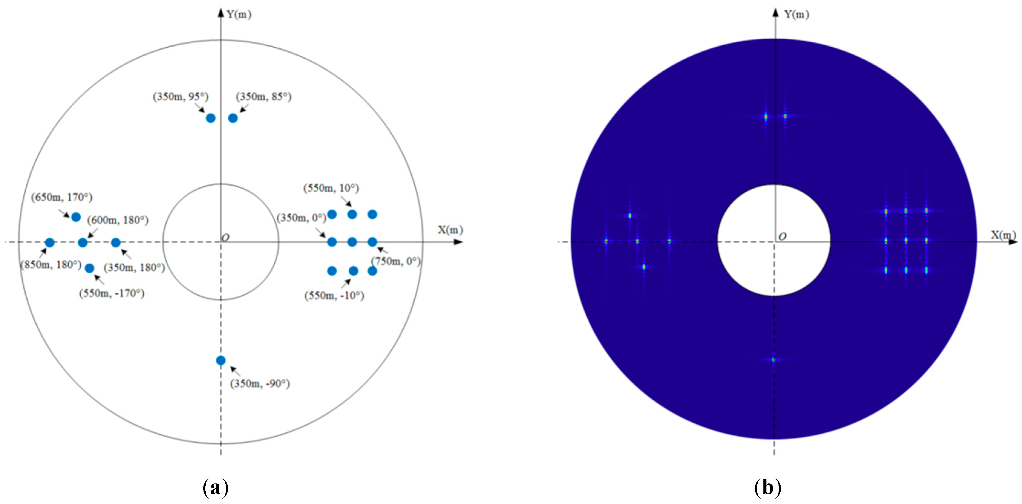
An imaged scene with a total of 17 targets located around the passive receiving platform is designed and shown as in Figure 5a. The imaging result of the designed scene is shown in Figure 5b.
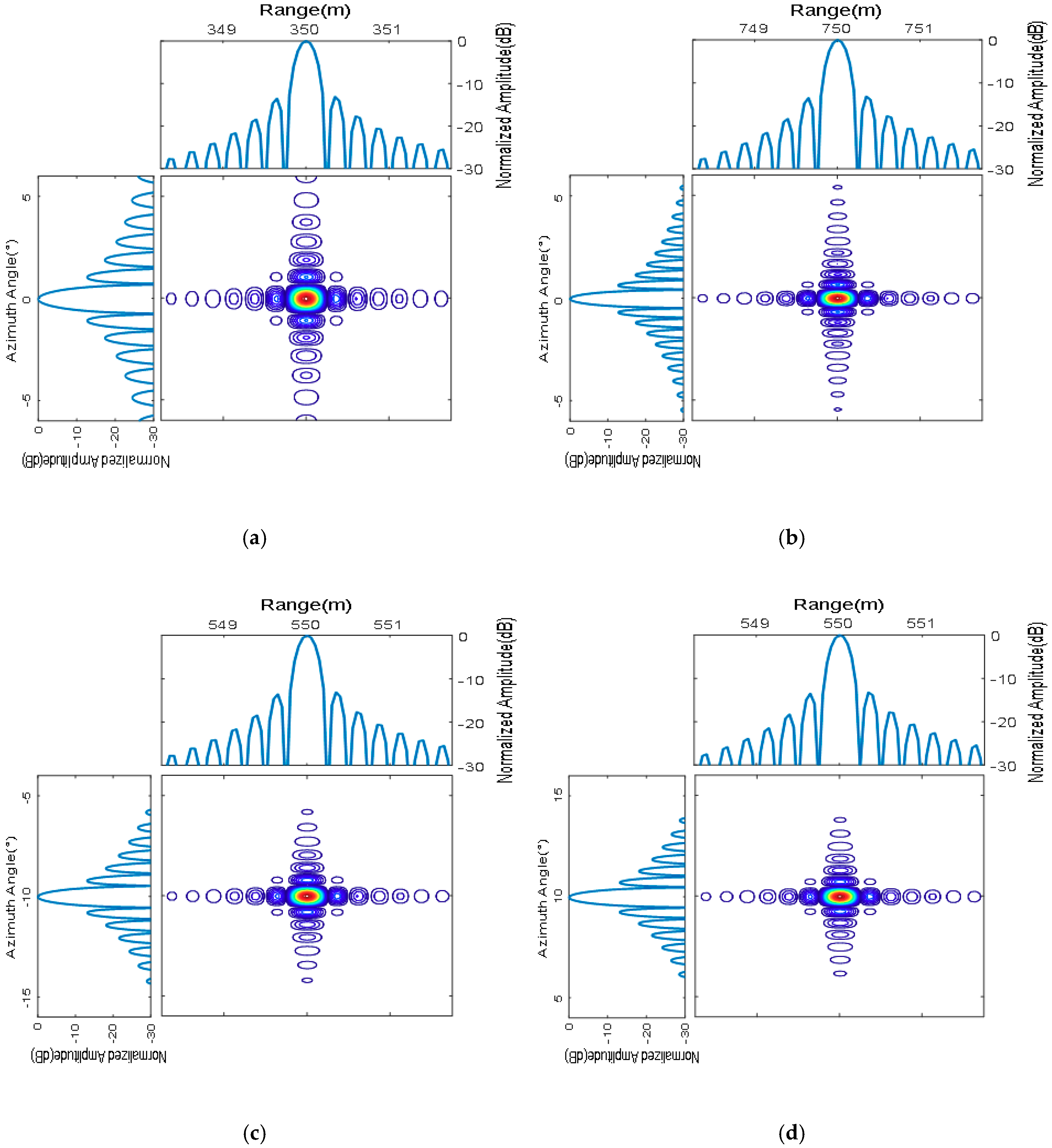
In order to further validate the proposed imaging approach, point targets P1, P2, P3 and P4, where position is located at (350 m, 0°), (750 m, 0°), (550 m, −10°), (550 m, 10°), respectively, are chosen to be measured and analyzed. The contours and the range direction and azimuth response function of the four targets P1, P2, P3 and P4 are shown in Figure 6, and all four imaged targets have good focusing behavior. Figure 6a,d show the focus results of the targets with the same angle but with different target distance, while Figure 6b,c show the focus results of the targets with the same target distance but different angles. As shown in Figure 6a,b, the ground range resolution has a poor performance when the target is close to the transmitter. With reference to Figure 6c,d, the azimuth angular resolution consists of the same radius distance. The specific imaging performance of targets P1, P2, P3 and P4 is computed and summarized in Table 2, where PSLR represents peak sidelobe ratio and ISLR refers to the integrated sidelobe ratio. In Table 2, the results of the actual measured ground-range resolutions and azimuth angular resolutions of the four selected targets are listed, and compared with the theoretically resolutions. Measured performance of imaging results listed in Table 2 is consistent with the theoretical analysis result, and also validates the proposed method.

6. Conclusions

In order to obtain full azimuth imaging quickly and counter the vulnerability of the conventional monostatic SAR, a novel BiSAR with a passive arc antenna and a stationary transmitter named as AA-BiSAR was proposed in this paper. The imaging geometry of AA-BiSAR was presented, and the echo signal model was developed. To implement the special RCMC under conditions of the BiSAR range history and the azimuth direction arc synthetic array, a novel imaging algorithm based on keystone transform was proposed according to the imaging geometry. In the proposed imaging approach, the movement of the target cross range unit was corrected through the keystone transform. Furthermore, both azimuth angular and ground-range resolution of AA-BiSAR were analyzed, and the azimuth angular resolution was independent on the location of the stationary transmitter. As a result, the transmitter could be located far away from the passive arc-array receiver, and this phenomenon makes AA-BiSAR attractive especially for military reconnaissance. The results of numerical simulation experiments on point targets validated the proposed imaging approach.

Author Contributions

All the authors made a contribution to this work. W.X. and K.L. proposed the idea and wrote the paper; P.H. conceived and designed the experiments; W.T. performed the experiments; Z.G. and Y.L. revised the manuscript.

Funding

This research was funded by National Equipment Pre-Research Foundation of China, grant number JZX7Y20190253040501 and JZX7Y20190253040901, Inner Mongolia Autonomous Region Foundation for Distinguished Young Scientists, grant number 2017JQ10, Inner Mongolia Science and Technology Innovation Guidance Project, grant number KCBJ2017 and KCBJ2018014 and National Natural Science Foundation Youth Fund of China, grant number 61701264.

Conflicts of Interest

The authors declare no conflict of interest.

References

  1. Cumming, I.G.; Wong, F.H. Digital Signal Processing of Synthetic Aperture Radar Data; Artech House: Norwood, MA, USA, 2005. [Google Scholar]
  2. An, D.; Huang, X.; Tian, J.; Zhou, Z. Extended nonlinear chirp scaling algorithm for high-resolution Highly squint SAR data focusing. IEEE Trans. Geosci. Remote Sens. 2012, 50, 3595–3609. [Google Scholar] [CrossRef]
  3. Lombardini, F.; Viviani, F. 4D characterization of short- and long-term height-varying decorrelated forest SAR backscattering. In Proceedings of the 2015 IEEE International Geoscience and Remote Sensing Symposium (IGARSS), Milan, Italy, 26–31 July 2015; pp. 1547–1550. [Google Scholar]
  4. Lombardini, F.; Viviani, F. Multidimensional SAR tomography: Advances for urban and prospects for forest/ice applications. In Proceedings of the 2014 11th European Radar Conference, Rome, Italy, 8–10 October 2014; pp. 225–228. [Google Scholar]
  5. Pieraccini, M.; Miccinesi, L. An Interferometric MIMO Radar for bridge monitoring. IEEE Geosci. Remote Sens. Lett. 2019, 16, 1–5. [Google Scholar] [CrossRef]
  6. Pieraccini, M.; Miccinesi, L. Bistatic ArcSAR. In Proceedings of the 2018 2nd URSI Atlantic Radio Science Meeting (AT-RASC), Gran Canaria, Spain, 28 May–1 June 2018; pp. 1–4. [Google Scholar]
  7. Arii, M.; Yamada, H.; Kojima, S.; Ohki, M. Review of the Comprehensive SAR Approach to Identify Scattering Mechanisms of Radar Backscatter from Vegetated Terrain. Electronics 2019, 8, 1098. [Google Scholar] [CrossRef]
  8. Huang, P.P.; Deng, Y.K.; Xu, W. Research on multiple-input and multiple-output SAR imaging based on CS algorithm. J. Univ. Electron. Sci. Technol. China 2012, 41, 222–226. [Google Scholar]
  9. Huang, P.P.; Li, H.C.; Feng, F.; Huang, M. The waveform analysis and signal processing for space-borne MIMO-SAR. In Proceedings of the European Conference on Synthetic Aperture Radar, Nuremberg, Germany, 23–26 April 2012. [Google Scholar]
  10. Hu, R.; Peng, Z.; Ma, J. A vehicle target recognition algorithm for wide-angle SAR based on joint feature set matching. Electronics 2019, 8, 1252. [Google Scholar] [CrossRef]
  11. Wang, X.; Qiao, L. Refocusing of Multiple Moving Targets Based on the Joint Sparse Processing of One Channel Synthetic Aperture Radar Imagery Patches. Electronics 2019, 8, 1215. [Google Scholar] [CrossRef]
  12. Huang, P.; Tan, W.; Su, Y. MIMO-SAR imaging technology for helicopter-borne based on ARC antenna array. In Proceedings of the Geoscience & Remote Sensing Symposium, Milan, Italy, 26–31 July 2015. [Google Scholar]
  13. Huang, P.P. Research on imaging algorithm with MIMO-SAR based on arc antenna array. In Proceedings of the High Resolution Earth Observation Confernence, Beijing, China, 1 December 2014. [Google Scholar]
  14. Huang, P.P.; Tan, W.X.; Ying, S.; Chi, W. Research on helicopter-borne MIMO microwave imaging technology based on arc antenna array. J. Radars 2015, 4, 11–19. [Google Scholar]
  15. Michelini, A.; Viviani, F.; Mayer, L. Introduction to IBIS-ArcSAR a circular scanning GB-SAR system for deformation monitoring. In Proceedings of the 4th Joint International Symposium on Deformation Monitoring (JISDM), Athens, Greece, 15–17 May 2019. [Google Scholar]
  16. Viviani, F.; Michelini, A.; Mayer, L.; Coppi, F. IBIS-ArcSAR: An innovative ground-based SAR system for slope monitoring. In Proceedings of the IGARSS 2018—2018 IEEE International Geoscience and Remote Sensing Symposium, Valencia, Spain, 22–27 July 2018. [Google Scholar]
  17. Huang, Z.; Sun, J.; Tan, W.; Huang, P.; Han, K. Investigation of wavenumber domain imaging algorithm for ground-based arc array SAR. Sensors 2017, 17, 2950. [Google Scholar] [CrossRef]
  18. Pieraccini, M.; Miccinesi, L. ArcSAR: theory, simulations, and experimental verification. IEEE Trans. Microw. Theory Tech. 2017, 65, 1–9. [Google Scholar] [CrossRef]
  19. Miccinesi, L.; Pieraccini, M. ArcSAR for detecting target elevation. Electron. Lett. 2016, 52, 1559–1561. [Google Scholar]
  20. Luo, Y.; Song, H.; Wang, R.; Deng, Y.; Zhao, F.; Zheng, X. Arc FMCW SAR and applications in ground monitoring. IEEE Trans. Geosci. Remote Sens. 2014, 52, 5989–5998. [Google Scholar] [CrossRef]
  21. Lee, H.; Lee, J.H.; Kim, K.E.; Sung, N.H.; Cho, S.J. Development of a truck-mounted arc-Scanning synthetic aperture radar. IEEE Trans. Geosci. Remote Sens. 2014, 52, 2773–2779. [Google Scholar] [CrossRef]
  22. Chen, P.; Cao, Z.; Chen, Z.; Yu, C. Sparse DOD/DOA estimation in a bistatic MIMO radar with mutual coupling effect. Electronics 2018, 7, 341. [Google Scholar] [CrossRef]
  23. An, H.; Wu, J.; Sun, Z.; Yang, J. A two-step nonlinear chirp scaling method for multichannel GEO spaceborne-airborne bistatic SAR spectrum reconstructing and focusing. IEEE Trans. Geosci. Remote Sens. 2019, 57, 3713–3728. [Google Scholar] [CrossRef]
  24. Comblet, F.; Khenchaf, A.; Baussard, A.; Pellen, F. Bistatic Synthetic Aperture Radar Imaging: Theory, Simulations, and Validations. IEEE Trans. Antennas Propag. 2006, 54, 3529–3540. [Google Scholar] [CrossRef]
  25. Wu, J.; Sun, Z.; An, H.; Qu, J.; Yang, J. Azimuth signal multichannel reconstruction and channel configuration design for geosynchronous spaceborne-airborne bistatic SAR. IEEE Trans. Geosci. Remote Sens. 2019, 57, 1861–1872. [Google Scholar] [CrossRef]
  26. Zhang, Q.; Wu, J.; Li, Z.; Miao, Y.; Huang, Y.; Yang, J. PFA for bistatic forward-looking SAR mounted on high-speed maneuvering platforms. IEEE Trans. Geosci. Remote Sens. 2019, 57, 6018–6036. [Google Scholar] [CrossRef]
  27. Walterscheid, I.; Ender, J.H.G.; Brenner, A.R.; Loffeld, O. Bistatic SAR processing and experiments. IEEE Trans. Geosci. Remote Sens. 2006, 44, 2710–2717. [Google Scholar] [CrossRef]
  28. Yates, G.; Home, A.M.; Blake, A.P.; Middleton, R. Bistatic SAR image formation. IEE Proc. Radar Sonar Navig. 2006, 153, 208–213. [Google Scholar] [CrossRef]
  29. Wang, R.; Loffeld, O.; Neo, Y.L.; Nies, H.; Walterscheid, I.; Espeter, T.; Klare, J.; Ender, J. Focusing Bistatic SAR Data in Airborne/Stationary Configuration. IEEE Trans. Geosci. Remote Sens. 2009, 48, 452–465. [Google Scholar] [CrossRef]
  30. Xie, H.; Shi, S.; An, D.; Wang, G.; Wang, G.; Hui, X.; Huang, X.; Zhou, Z.; Chao, X.; Feng, W. Fast factorized backprojection algorithm for one-stationary bistatic spotlight circular SAR Image formation. IEEE J. Sel. Top. Appl. Earth Obs. Remote Sens. 2017, 10, 1494–1510. [Google Scholar] [CrossRef]
  31. Li, Z.; Wu, J.; Huang, Y.; Sun, Z.; Yang, J. One-stationary bistatic forward-looking SAR for moving target detection and imaging with a linear antenna array. In Proceedings of the Geoscience & Remote Sensing Symposium, Quebec City, QC, Canada, 13–18 July 2014. [Google Scholar]
  32. Xie, H.; An, D.; Huang, X.; Zhou, Z. Research on spatial resolution of one-stationary bistatic ultrahigh frequency ultrawidebeam–ultrawideband SAR based on scattering target wavenumber domain support. IEEE J. Sel. Top. Appl. Earth Obs. Remote Sens. 2015, 8, 1782–1798. [Google Scholar] [CrossRef]
  33. Wu, J.; Li, Z.; Huang, Y.; Yang, J.; Liu, Q.H. Omega-K imaging algorithm for one-stationary bistatic SAR. IEEE Trans. Aerosp. Electron. Syst. 2014, 50, 33–52. [Google Scholar] [CrossRef]
  34. Dai, C.; Zhang, X.; Shi, J. Range cell migration correction for bistatic SAR image formation. IEEE Geosci. Remote Sens. Lett. 2011, 9, 124–128. [Google Scholar] [CrossRef]
  35. Perry, R.P.; Dipietro, R.C.; Fante, R.L. SAR imaging of moving targets. IEEE Trans. Aerosp. Electron. Syst. 1999, 35, 188–200. [Google Scholar] [CrossRef]
  36. Kai, H.; Liu, Y.; Hu, J.; Jiang, W.; Xiang, L. A novel imaging method for fast rotating targets based on the segmental pseudo keystone transform. IEEE Trans. Geosci. Remote Sens. 2011, 49, 1464–1472. [Google Scholar]
  37. Li, G.; Xia, X.G.; Peng, Y.N. Doppler Keystone Transform: An Approach Suitable for Parallel Implementation of SAR Moving Target Imaging. IEEE Geosci. Remote Sens. Lett. 2008, 5, 573–577. [Google Scholar] [CrossRef]
  38. Li, W.; Yang, J.; Huang, Y. Keystone transform-based space-variant range migration correction for airborne forward-looking scanning radar. Electron. Lett. 2012, 48, 121–122. [Google Scholar] [CrossRef]
  39. Zhu, D.; Yong, L.; Zhu, Z. A Keystone Transform Without Interpolation for SAR Ground Moving-Target Imaging. IEEE Geosci. Remote Sens. Lett. 2007, 4, 18–22. [Google Scholar] [CrossRef]
  40. Rodriguez-Cassola, M.; Baumgartner, S.V.; Krieger, G.; Moreira, A. Bistatic TerraSAR-X/F-SAR spaceborne-airborne SAR experiment: Description, data processing, and results. IEEE Trans. Geosci. Remote Sens. 2010, 48, 781–794. [Google Scholar] [CrossRef] [Green Version]
  41. Krieger, G.; Fiedler, H.; Hounam, D.; Moreira, A. Analysis of System Concepts for Bi-and Multistatic SAR Missions. In Proceedings of the IEEE International Geoscience & Remote Sensing Symposium, Toulouse, France, 21–25 July 2003. [Google Scholar]
  42. Cardillo, G.P. On the use of the gradient to determine bistatic SAR resolution. In Proceedings of the Antennas & Propagation Society International Symposium, Dallas, TX, USA, 7–11 May 1990. [Google Scholar]
  43. Qiu, X.; Ding, C.; Hu, D. Bistatic SAR Data Processing Algorithms; John Wiley & Sons: New York, NY, USA, 2012. [Google Scholar]
Figure 1. The receiving system of an arc-array bistatic synthetic aperture radar (AA-BiSAR). (a) The configuration of the receiving system; (b) the structure of the passive arc antenna array.
Electronics 08 01389 g001
Figure 2. The imaging principle and geometry of the AA-BiSAR system. (a) The work mode; (b) the imaging geometry; (c) the top view of the imaging geometry; (d) the side view of the imaging geometry.
Electronics 08 01389 g002
Figure 3. Procedure of AA-BiSAR imaging approach based on keystone transform.
Electronics 08 01389 g003
Figure 4. The resolution of targets with different locations. (a) The azimuth angular resolution; (b) the ground-range resolution.
Electronics 08 01389 g004
Figure 5. The position and the imaging result of targets. (a) The positions of targets; (b) the imaging results of targets.
Electronics 08 01389 g005
Figure 6. Imaging results of targets with different distances and different azimuth angles. (a) Point P1 at (350 m, 0°); (b) Point P4 at (750 m, 0°); (c) Point P3 at (550 m, −10°); (d) Point P4 at (550 m, 10°).
Electronics 08 01389 g006
Table 1. Numerical simulation experiment parameters.
SymbolDefinitionValue
f 0 Carrier Frequency40.5 GHz
B r Signal Bandwidth650 MHz
T r Sweep Time0.15 ms
R r Arc-Array Radius0.6 m
θ a Array Beam width (−3 dB)56°
H r Height of Receiving Platform650 m
( X t , Y t , H t ) Position of Transmitting Platform(200 m, 3000 m, 600 m)
Table 2. Measured parameters of the selected targets.
TargetRangeAzimuth
Ground-Range Resolutions (m)PSLR (dB)ISLR (dB)Azimuth Angular Resolutions (°)PSLR (dB)ISLR (dB)
Theoretical ValuesActual ResultsTheoretical ValuesActual Results
P10.4780.481−13.206−9.4980.9510.955−12.702−8.879
P20.4930.495−13.213−9.4990.6330.634−12.683−8.851
P30.4620.464−13.402−9.5360.7220.726−12.697−8.985
P40.5510.557−13.193−9.2120.7220.729−12.636−8.803