Technical and Economic Assessment of VSC-HVDC Transmission Model: A Case Study of South-Western Region in Pakistan

 ,
, 
 ,
,  and
and
Abstract
1. Introduction
2. Overview of HVDC Systems
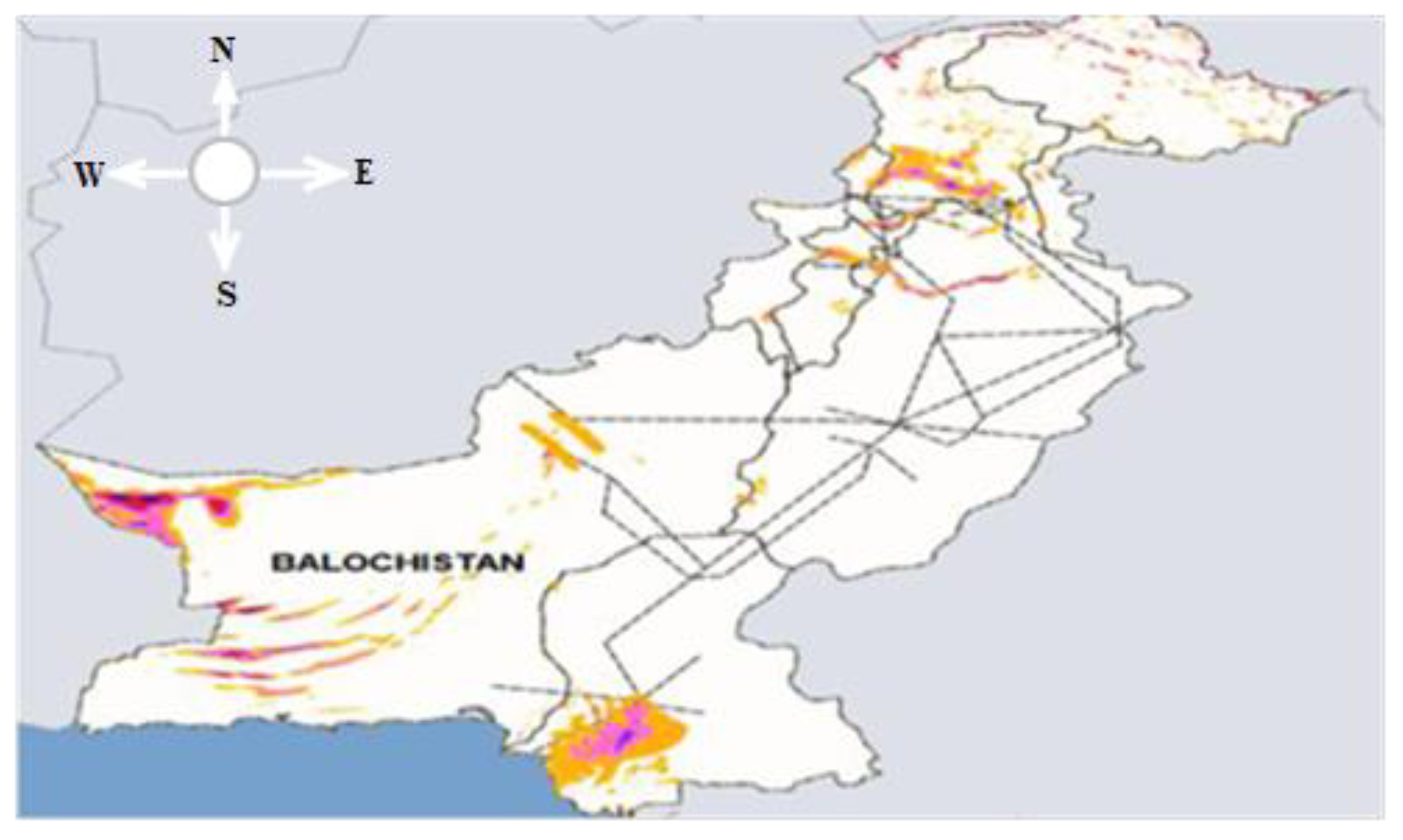
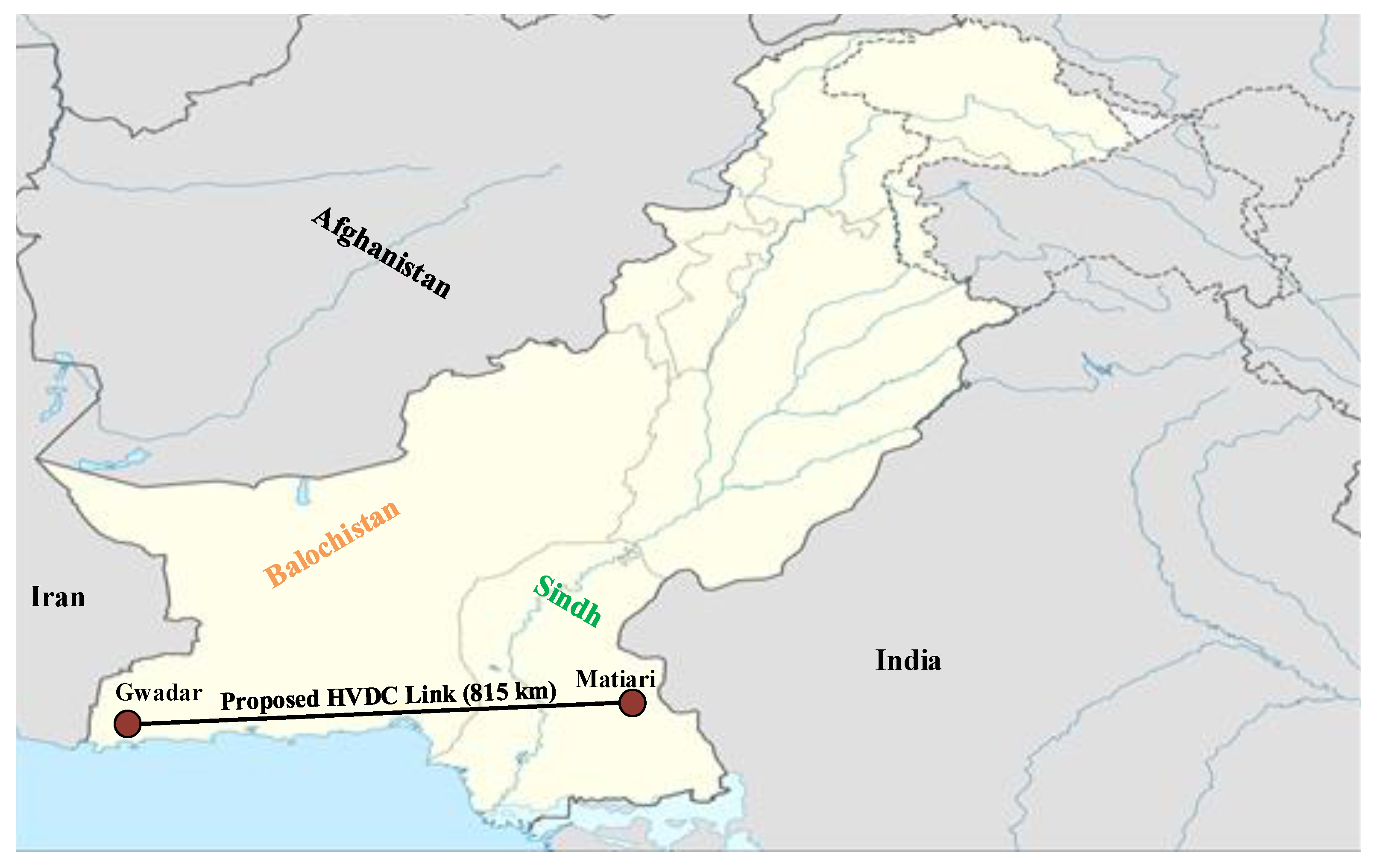
3. Deployment of Proposed Transmission Line
4. VSC-HVDC System Theory and Simulation
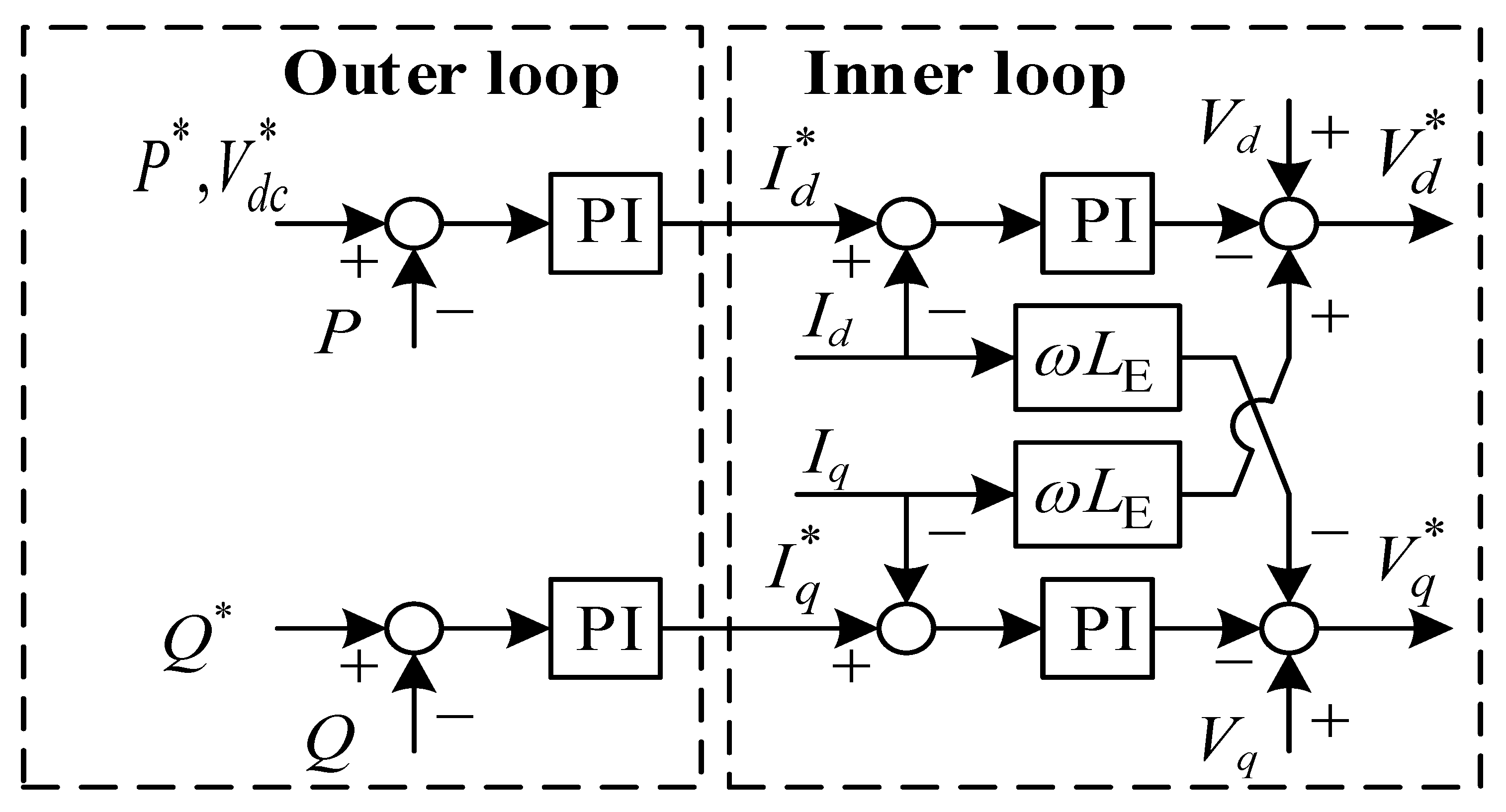
4.1. Converter Control
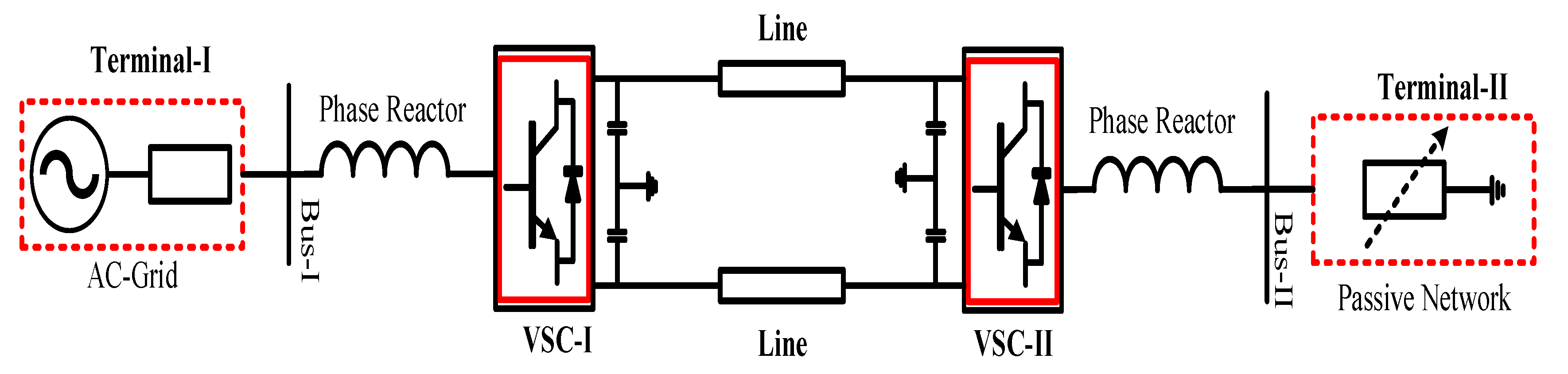
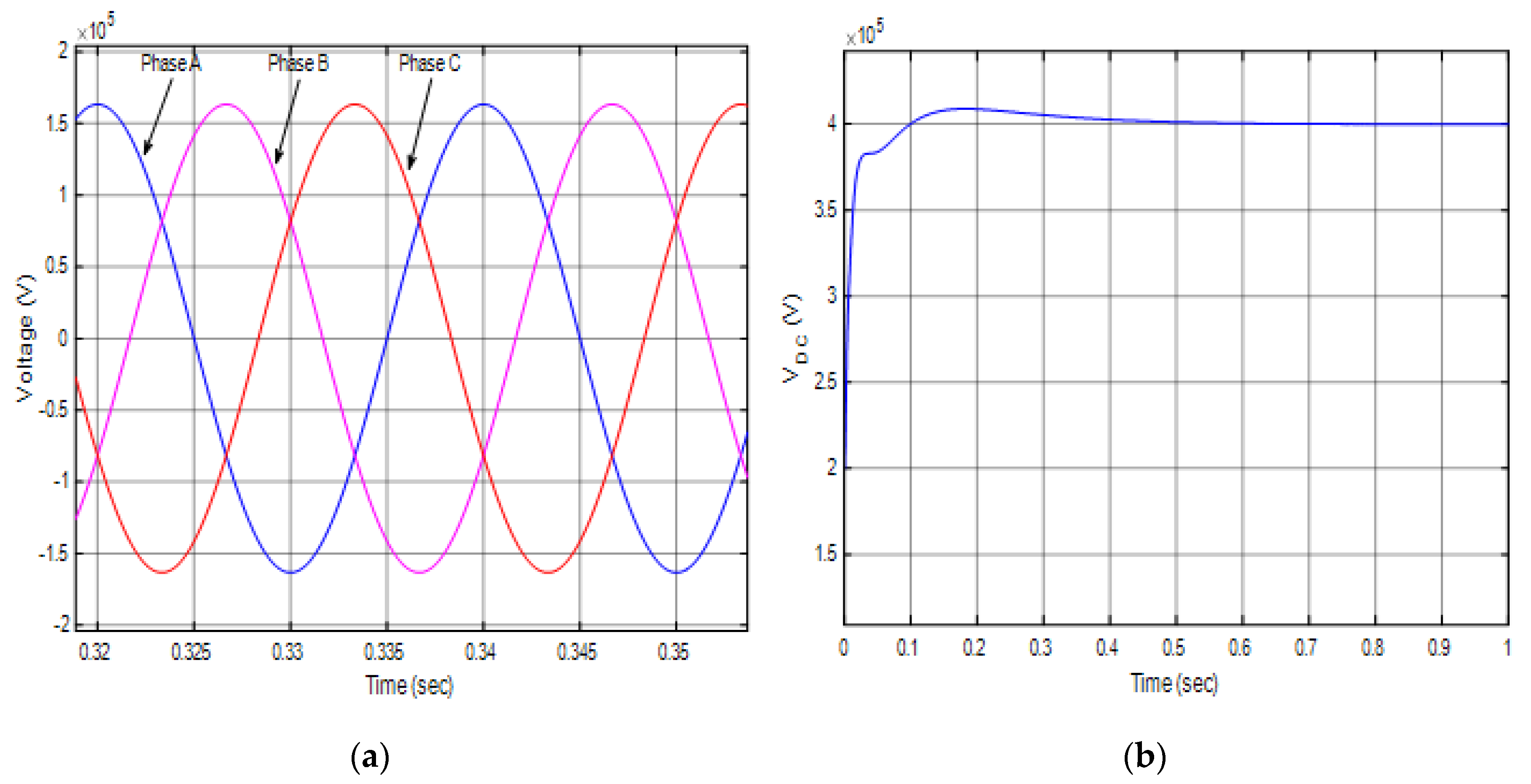
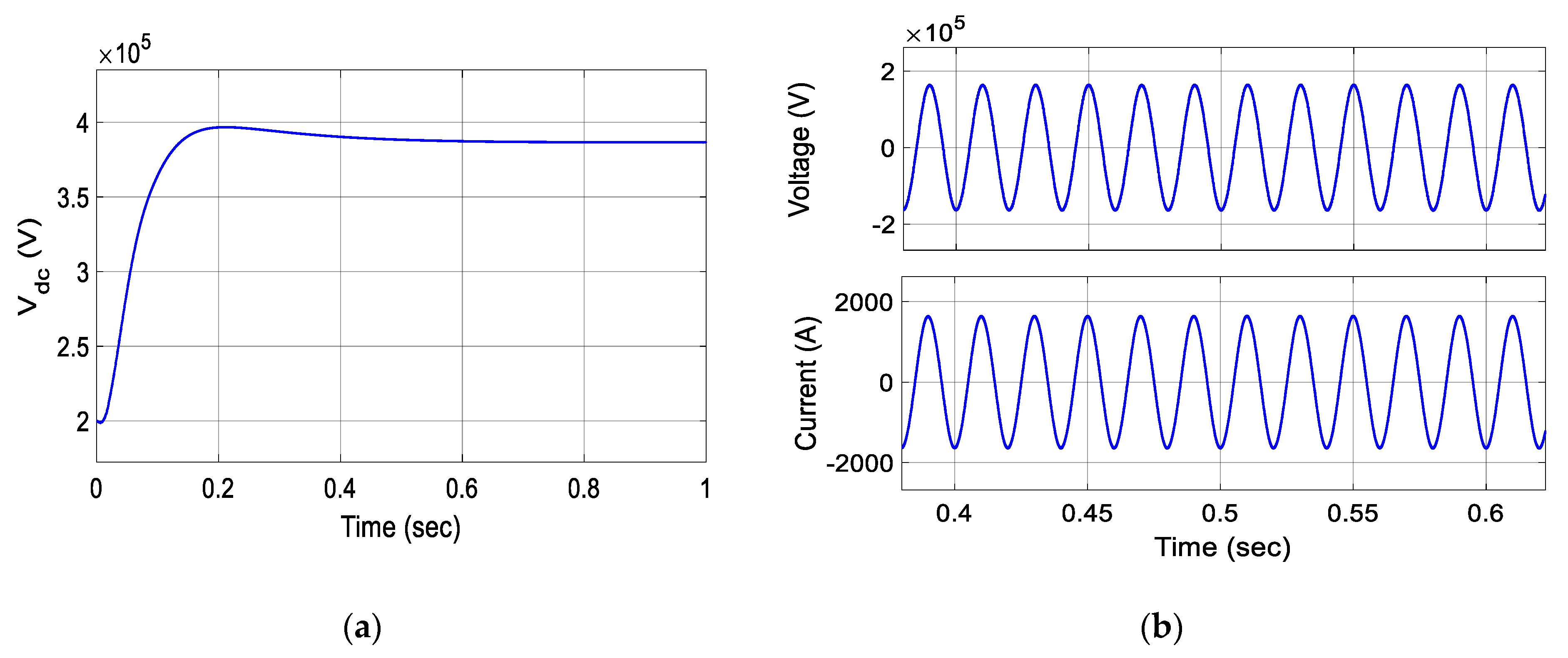
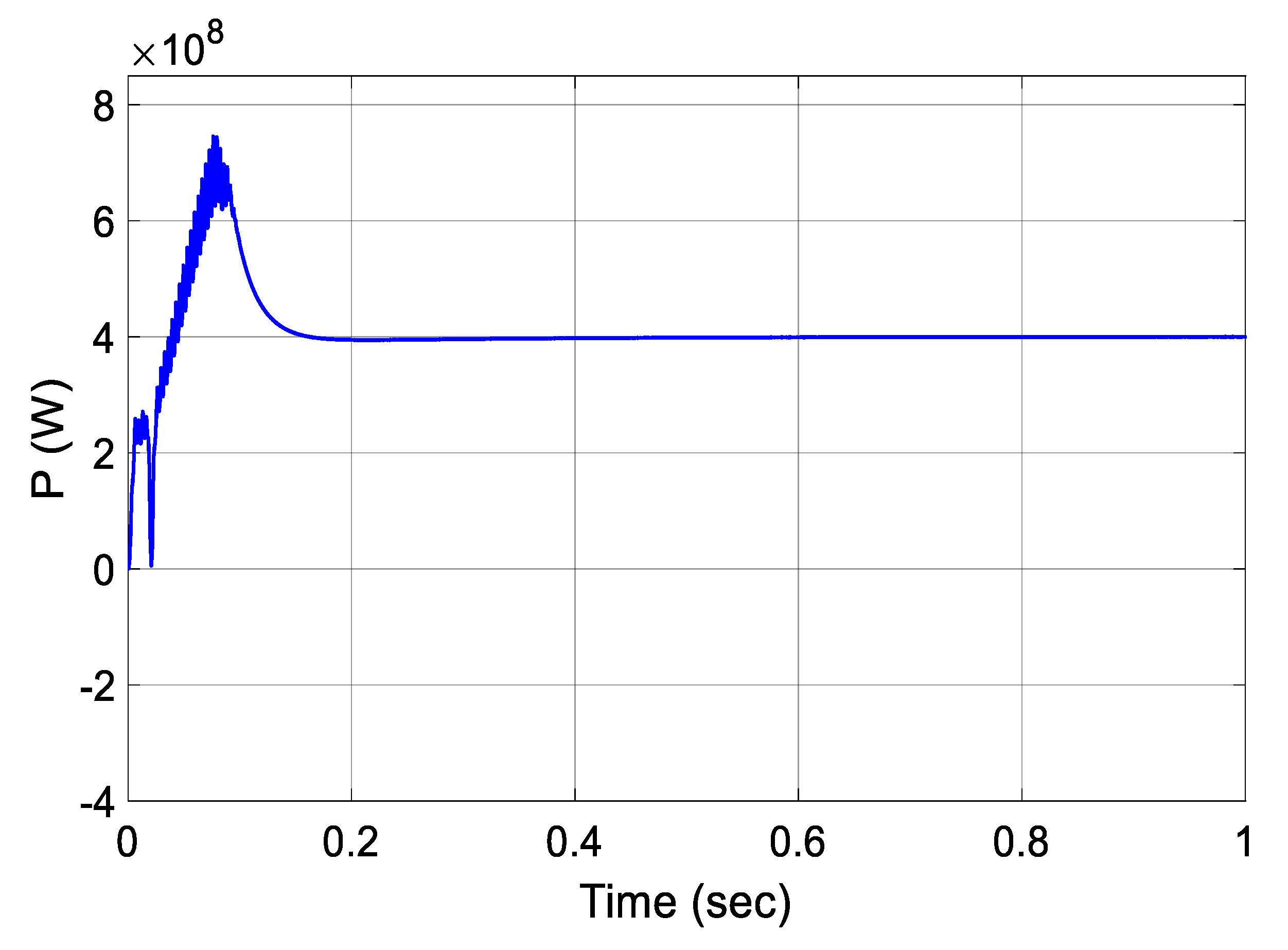
4.2. Two-Terminal Model Simulation
5. Cost Assessment
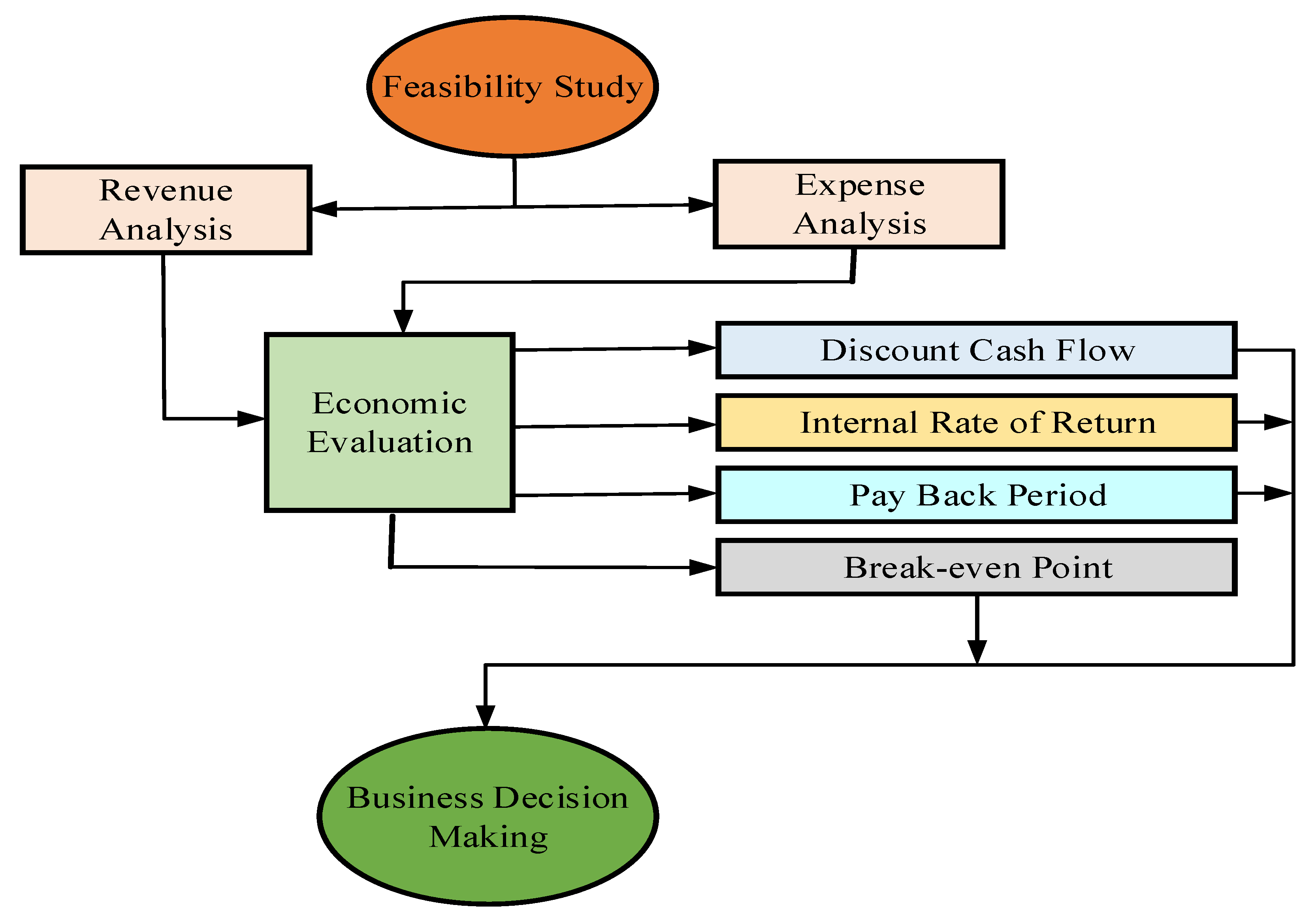
5.1. Methodology
5.2. Investment Cost Analysis
5.3. Annual Cost
5.4. Discounted Cash Flow (DCF) Analysis
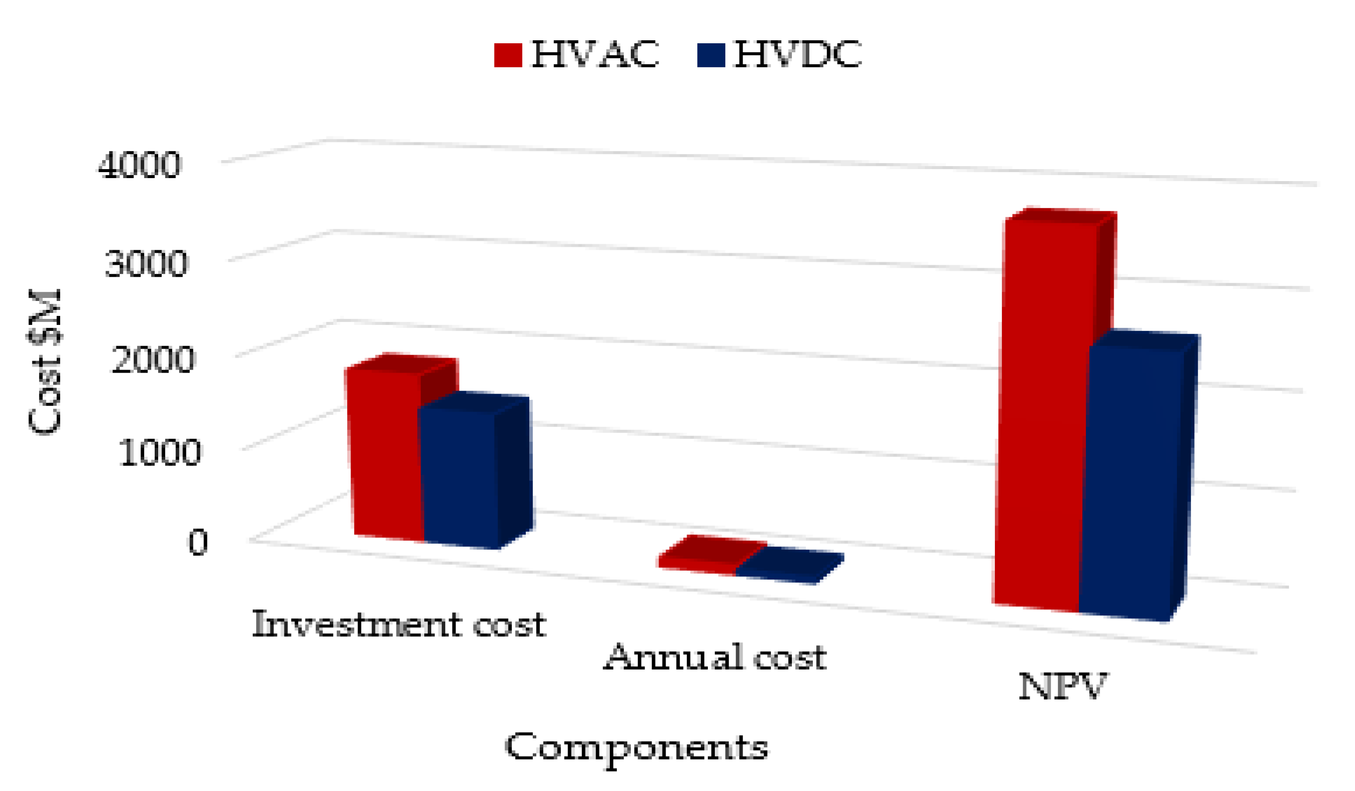
5.5. HVDC Systems’ Economics Comparison
6. Conclusions
Author Contributions
Funding
Conflicts of Interest
Nomenclature
| Active power | |
| Reactive power | |
| Annual cost | |
| Annuity factor | |
| Discount factor | |
| Taxation rate | |
| Depreciation value |
Abbreviations
| CPEC | China Pakistan Economic Corridor |
| VSC | Voltage source converter |
| MMC | Modular multilevel converter |
| HVDC | High voltage direct current |
| HVAC | High voltage alternate current |
| LCC | Line commutated converter |
| DCF | Discounted cash flow method |
| NPV | Net present value |
| Cda | Discounted annual cost |
| Ci | Initial investment cost |
| Cost of substation | |
| Cost of land | |
| Cost of overhead transmission line | |
| Cost of reactive power compensations |
Appendix A

| System Capacity | 400 MVA |
| Line Current | 1 kA |
| Line Voltage | 400 kV |
| Active Power | 400 MW |
| Distance | 800 Km |
| RL | 0.0256 Ω/Km |
| LL | 468 µH/Km |
| CL | 0.0124 µF/Km |
References
- Rehman, A.; Deyuan, Z. Pakistan’s energy scenario: A forecast of commercial energy consumption and supply from different sources through 2030. Energ. Sustain. Soc. 2018, 8, 26. [Google Scholar] [CrossRef]
- Gul, M.; Tai, N.; Huang, W.; Nadeem, M.H.; Yu, M. Assessment of Wind Power Potential and Economic Analysis at Hyderabad in Pakistan: Powering to Local Communities Using Wind Power. Sustainability 2019, 11, 1391. [Google Scholar] [CrossRef]
- Kamran, M. Current status and future success of renewable energy in Pakistan. Renew. Sustain. Energy Rev. 2018, 82, 609–617. [Google Scholar] [CrossRef]
- Adnan, S.; Khan, A.H.; Haider, S.; Mahmood, R. Solar energy potential in Pakistan. J. Renew. Sustain. Energy 2012, 4, 032701. [Google Scholar] [CrossRef]
- National Renewable Energy Laboratory (NREL), International Data. Available online: https://www.nrel.gov/gis/data-international.html (accessed on 24 October 2019).
- Province Wise Provisional Results of Census—2017. Available online: http://www.pbs.gov.pk/sites/default/files/PAKISTAN%20TEHSIL%20WISE%20FOR%20WEB%20CENSUS_2017 (accessed on 20 May 2019).
- Pakistan Transmission Lines. Available online: https://maps.nrel.gov/rede-pakistan/ (accessed on 24 October 2019).
- Hur, D. Economic considerations underlying the adoption of HVDC and HVAC for the connection of an offshore wind farm in Korea. J. Electr. Eng. Technol. 2012, 7, 157–162. [Google Scholar] [CrossRef]
- Meah, K.; Sadrul, U. Comparative evaluation of HVDC and HVAC transmission systems. In Proceedings of the 2007 IEEE Power Engineering Society General Meeting, Tampa, FL, USA, 24–28 June 2007. [Google Scholar]
- Rudervall, R.; Charpentier, J.P.; Sharma, R. High voltage direct current (HVDC) transmission systems technology review paper. Energy Week 2000, 2000, 1–19. [Google Scholar]
- Candelaria, J.; Park, J.D. VSC-HVDC system protection: A review of current methods. In Proceedings of the 2011 IEEE/PES Power Systems Conference and Exposition, Phoenix, AZ, USA, 20–23 March 2011; pp. 1–7. [Google Scholar]
- Ahmad, M.; Wang, Z. A Hybrid DC Circuit Breaker with Fault-Current-Limiting Capability for VSC-HVDC Transmission System. Energies 2019, 12, 2388. [Google Scholar] [CrossRef]
- Yang, Q.; Blond, S.-L.; Aggarwal, R.; Wang, Y.; Li, J. New ANN method for multi-terminal HVDC protection relaying. Electr. Power Syst. Res. 2017, 148, 192–201. [Google Scholar] [CrossRef]
- Li, J.; Yang, Q.; Mu, H.; Blond, S.-L.; He, H. A new fault detection and fault location method for multi-terminal high voltage direct current of offshore wind farm. Appl. Energy 2018, 220, 13–20. [Google Scholar] [CrossRef]
- Nadeem, M.; Zheng, X.; Tai, N.; Gul, M. Identification and Isolation of Faults in Multi-terminal High Voltage DC Networks with Hybrid Circuit Breakers. Energies 2018, 5, 1086. [Google Scholar] [CrossRef]
- Nadeem, M.; Zheng, X.; Tai, N.; Gul, M.; Tahir, S. Analysis of propagation delay for multi-terminal high voltage direct current networks interconnecting the large-scale off-shore renewable energy. Energies 2018, 8, 2115. [Google Scholar] [CrossRef]
- Zhang, X.; Tai, N.; Wu, P.; Fan, C.; Zheng, X.; Huang, W. A New Theory for Locating Line Fault in Power System: Theoretical Part. IEEE Access 2019, 7, 37–46. [Google Scholar] [CrossRef]
- Bahrman, M.-P.; Johnson, B.-K. The ABCs of HVDC transmission technologies. IEEE Power Energy Mag. 2007, 5, 32–44. [Google Scholar] [CrossRef]
- Povh, D. Use of HVDC and FACTS. IEEE 2000, 88, 235–245. [Google Scholar] [CrossRef]
- Agelidis, V.G.; Demetriades, G.D.; Flourentzou, N. Recent advances in high-voltage direct-current power transmission systems. In Proceedings of the 2006 IEEE International Conference on Industrial Technology (ICIT), Mumbai, India, 15–17 December 2006; pp. 206–213. [Google Scholar]
- Committee IT and D. HVDC Project Listing 2006. Available online: http://www.ece.uidaho.edu/hvdcfacts/Projects/HVDCProjectsListingDec2006.pdf (accessed on 12 May 2019).
- List of HVDC Projects. Available online: https://ipfs.io/ipfs/QmXoypizjW3WknFiJnKLwHCnL72vedxjQkDDP1mXWo6uco/wiki/List_of_HVDC_projects.html (accessed on 24 October 2019).
- Rashid, M. Power Electronics Hand Book, 3rd ed.; Butterworth Heinemann, Elsevier: Waltham, MA, USA, 2011. [Google Scholar]
- ABB. High-Voltage Direct Current Transmission. Available online: https://new.abb.com/systems/hvdc (accessed on 24 October 2019).
- Flourentzou, N.; Agelidis, V.-G.; Demetriades, G.-D. VSC-based HVDC power transmission systems: An overview. IEEE Trans. Power Electron. 2009, 24, 592–602. [Google Scholar] [CrossRef]
- Raza, A.; Xu, D.-G.; Su, X.-W.; Li, W.-X. Invasion of high voltage direct current till 2014. In Proceedings of the 2014 IEEE International Conference on Control Science and Systems Engineering, Yantai, China, 29–30 December 2014. [Google Scholar]
- CPEC-Projects. Available online: http://cpec.gov.pk/progress-update (accessed on 20 May 2019).
- Shaikh, F.; Ji, Q.; Ying, F. Prospects of Pakistan–China energy and economic corridor. Renew. Sustain. Energy Rev. 2016, 59, 253–263. [Google Scholar] [CrossRef]
- Pakistan, Saudi Arabia Oil Project. Available online: https://tribune.com.pk/story/1913551/1-pakistan-saudi-arabia-agree-form-jwg-oil-projects/ (accessed on 23 May 2019).
- Qatar Investment in CPEC Gwadar. Available online: https://tribune.com.pk/story/1889424/1-qatar-expresses-interest-cpec-investment-gwadar/ (accessed on 23 May 2019).
- Chaudhuri, N.; Chaudhuri, B.; Majumder, R.; Yazdani, A. Multi-Terminal Direct-Current Grids: Modeling, Analysis, and Control; Wiley-IEEE Press: Hoboken, NJ, USA, 2014. [Google Scholar]
- Le Blond, S.; Bertho, R.; Coury, D.V.; Vieira, J.C.M. Design of protection schemes for multi-terminal HVDC systems. Renew. Sustain. Energy Rev. 2016, 56, 965–974. [Google Scholar] [CrossRef]
- Akagi, H.; Edson, H.-W.; Mauricio, A. Instantaneous Power Theory and Applications to Power Conditioning; John Wiley & Sons: Hoboken, NJ, USA, 2017. [Google Scholar]
- Jiang, B.-K.; Wang, Z.-X. The key technologies of VSC-MTDC and its application in China. Renew. Sustain. Energy Rev. 2016, 62, 297–304. [Google Scholar]
- Simkovic, M. The Evolution of Valuation in Bankruptcy. Am. Bankruptcy Law J. 2017, 91, 299. [Google Scholar] [CrossRef]
- Pakistan Sales Tax Rate. Available online: https://tradingeconomics.com/pakistan/sales-tax-rate (accessed on 15 July 2019).
- State Bank of Pakistan, Economic Data. Available online: http://www.sbp.org.pk/ecodata/index2.asp (accessed on 18 July 2019).
- Pletka, R.; Khangura, J.; Rawlins, A.; Waldren, E.; Wilson, D. Capital Costs for Transmission and Substations: Updated Recommendations for WECC Transmission Expansion Planning. Black and Veatch PROJECT 181374 (2014). Available online: https://www.academia.edu/14330724/CAPITAL_COSTS_FOR_TRANSMISSION_AND_SUBSTATIONS_Updated_Recommendations_for_WECC_Transmission_Expansion_Planning_Western_Electricity_Coordinating_Council (accessed on 18 July 2019).
- Construction of Chongqing-Hubei Back to Back DC Grid Interconnection Project. Available online: http://www.sgcc.com.cn/ywlm/mediacenter/corporatenews/05/340829.shtml (accessed on 27 October 2019).
- Cai, D.; Zhou, K.; Wang, W.; Liu, H.-G.; Cao, K.; Wang, Y. Influence of back-to-back VSC-HVDC project on the operation characteristics of Hubei power grid. J. Eng. 2017, 13, 801–805. [Google Scholar] [CrossRef]
- Sa Energy Transformation Rit-T Cost Estimate Report. Available online: https://www.electranet.com.au/wp-content/uploads/projects/2016/11/Cost-Estimate-Report.pdf (accessed on 27 October 2019).
- China Building Super Highway for Clean Power. Available online: https://gigaom.com/2012/05/14/china-building-super-highway-for-clean-power (accessed on 27 October 2019).
- A New Energy Network: HVDC Development in China. Available online: http://cleanandsecuregrid.org/2017/01/02/a-new-energy-network-hvdc-development-in-china (accessed on 27 October 2019).
- CPEC Projects. Available online: http://cpec.gov.pk/energyaccesed (accessed on 26 October 2019).


| Project Name | Year | Voltage (kV) | Power (MW) | Distance (km) | Type | Supplier |
|---|---|---|---|---|---|---|
| Three Gorges–Shanghai (China) | 2006 | 500 | 3000 | 1060 | Thy | ABB |
| Estlink (Estonia–Finland) | 2006 | 150 | 350 | 105 | IGB | ABB |
| NorNed (Netherland–Norway) | 2008 | 450 | 700 | 580 | Thy | ABB |
| Yunnan–Guangdong (China) | 2010 | 800 | 5000 | 1418 | Thy | Siemens |
| SAPEI (Italy) | 2011 | 500 | 1000 | 435 | Thy | ABB |
| BorWin1 (Germany) | 2012 | 150 | 400 | 200 | IGB | ABB |
| Mundra–Haryana (India) | 2012 | 500 | 2500 | 960 | Thy | Siemens |
| Zhoushan (China) | 2014 | 200 | 400 | 134 | IGB | NA |
| AL-link (Aland–Finland) | 2015 | 80 | 10 | 158 | IGB | ABB |
| Western Alberta Transmission Line (Canada) | 2015 | 500 | 1000 | 350 | Thy | NA |
| NordBalt (Sweden–Lithuania) | 2015 | 300 | 700 | 450 | IGB | ABB |
| Skagerrak 4 (Denmark Norway) | 2015 | 500 | 700 | 244 | IGB | Nexans, ABB |
| Jinsha River II–East China (China) | 2016 | 800 | 6400 | NA | Thy | NA |
| DolWin2 (Germany) | 2016 | 320 | 900 | 135 | IGB | ABB |
| SydVastlanken (Sweden) | 2016 | 300 | 720 | 260 | IGB | Alstom |
| Western HVDC Link (UK) | 2017 | 600 | 2200 | 422 | Thy | Prysmain Group, Siemens |
| Xinjiang–Anhui (China) | 2017 | 1100 | 10,000 | 3333 | Thy | NA |
| Operation/Function | VSC-HVDC | LCC-HVDC |
|---|---|---|
| Direction reversal | No external mechanical switches needed, current direction change is possible in the converter | Cannot change the current direction, need external switches |
| AC influences | Offer fault ride-through capability, No AC disturbances, a less loss of active power transfer | Possibly commutation failure; short circuit of the HVDC grid |
| AC Voltage Control | Allows active and reactive power control | Consumes 50 percent of reactive power (VAR), needed AC filters for VAR compensation |
| AC connections | Electrically can be connected to weak or black AC circuits | Connection limited to medium and high capacity circuits. |
| Multi-Terminals Options | No limitations | Limited to 3-terminals |
| Delivery period | 2 years | 3 years |
© 2019 by the authors. Licensee MDPI, Basel, Switzerland. This article is an open access article distributed under the terms and conditions of the Creative Commons Attribution (CC BY) license (http://creativecommons.org/licenses/by/4.0/).
Share and Cite
Gul, M.; Tai, N.; Huang, W.; Nadeem, M.H.; Ahmad, M.; Yu, M. Technical and Economic Assessment of VSC-HVDC Transmission Model: A Case Study of South-Western Region in Pakistan. Electronics 2019, 8, 1305. https://doi.org/10.3390/electronics8111305
Gul M, Tai N, Huang W, Nadeem MH, Ahmad M, Yu M. Technical and Economic Assessment of VSC-HVDC Transmission Model: A Case Study of South-Western Region in Pakistan. Electronics. 2019; 8(11):1305. https://doi.org/10.3390/electronics8111305
Chicago/Turabian StyleGul, Mehr, Nengling Tai, Wentao Huang, Muhammad Haroon Nadeem, Muhammad Ahmad, and Moduo Yu. 2019. "Technical and Economic Assessment of VSC-HVDC Transmission Model: A Case Study of South-Western Region in Pakistan" Electronics 8, no. 11: 1305. https://doi.org/10.3390/electronics8111305
APA StyleGul, M., Tai, N., Huang, W., Nadeem, M. H., Ahmad, M., & Yu, M. (2019). Technical and Economic Assessment of VSC-HVDC Transmission Model: A Case Study of South-Western Region in Pakistan. Electronics, 8(11), 1305. https://doi.org/10.3390/electronics8111305