Review

Insight on Electronic Travel Aids for Visually Impaired People: A Review on the Electromagnetic Technology

Department of Engineering, University of Messina, Messina 98166, Italy
*
Author to whom correspondence should be addressed.
Electronics 2019, 8(11), 1281; https://doi.org/10.3390/electronics8111281
Submission received: 15 October 2019 / Revised: 25 October 2019 / Accepted: 28 October 2019 / Published: 4 November 2019
(This article belongs to the Special Issue Design and Application of Biomedical Circuits and Systems)

Abstract

:
This review deals with a comprehensive description of the available electromagnetic travel aids for visually impaired and blind people. This challenging task is considered as an outstanding research area due to the rapid growth in the number of people with visual impairments. For decades, different technologies have been employed for solving the crucial challenge of improving the mobility of visually impaired people, but a suitable solution has not yet been developed. Focusing this contribution on the electromagnetic technology, the state-of-the-art of available solutions is demonstrated. Electronic travel aids based on electromagnetic technology have been identified as an emerging technology due to their high level of achievable performance in terms of accuracy, flexibility, lightness, and cost-effectiveness.

1. Introduction

It is estimated that 188.5 million people worldwide have mild vision impairment, 217 million have moderate-to-severe vision impairment, and 36 million people are blind [1].
This is a continuously growing number that has fueled the interest of many in in the pursuit of improving the quality of life of those affected by blindness [2,3,4,5,6].
Usually, the mobility of visually impaired people is addressed by the use of travel supports, with the traditional white-cane being the most renowned and still the most popular. However, there are many electronic travel aids (ETAs) available to make mobility safer and more familiar for both inside and outside use.
The National Research Council published a list of the most important requirements of an ETA [7,8]:
1)
Detection of obstacles from ground level to height of the head;
2)
Information about the travel surface;
3)
Detection of objects bordering the travel path for shore-lining and projection;
4)
Distant object and cardinal direction information for the projection of a straight line;
5)
Location of landmarks and identification information;
6)
Information for enhancing self-familiarization and for creating a mental map of the environment.
These six points represent the landmark for designing an effective ETA. The first three requirements provide indications about the obstacles that an ETA should be able to detect. Points four to six suggest additional information is needed for easier and safer movement in a complex environment.
Since eighty years ago, when the first ETAs were introduced, the work of researchers has concentrated on the design of better aids, but as yet these have not materialized. [9]. To date, none of the available aids has fulfilled all the requirements to fully satisfy users’ expectations.
The ETAs are usually divided into two categories: primary and secondary aids. Primary aids allow autonomous movement without other aids since they provide all the required information independently. Secondary aids only enhance the mobility and must be used in conjunction with other aids (e.g., primary aids). Moreover, ETAs can be classified as mobility and navigation aids, where the former help the user in detecting and avoiding obstacles in their path and the latter allow to the user to find the path itself from the starting point to the destination [10].
Different technologies have been used with the aim of creating better devices, the most significant being based on ultrasonic sensors and optical/vision systems [11,12,13,14,15,16,17].
Although technological advancement has reached an elevated level of maturity and a variety of devices are available on the market, ultrasonic systems have limitations [10]. To specify, the maximum detectable range is limited when smooth surfaces need to be detected, even worse if the angle of incidence of the ultrasonic beam is small. Furthermore, due to the relatively large radiation beam, it is difficult for small apertures to be accurately detected (e.g., the presence of doors). Nevertheless, this kind of aid is widely used due to the easy-to-access technology and the availability of low-cost ultrasonic sensors.
ETAs based on optical technologies are very robust in terms of object detection capabilities under normal operating conditions. They typically employ cameras, and the target recognition is provided by means of complex algorithms [18]. The main drawbacks are due to the high sensitivity to ambient light, which can seriously limit the system performance, especially in outdoor environments [10]. Additional issues are the strong dependence on the optical properties of obstacles and the bulky dimensions of the devices.
Due to the lack of a competitive and robust technology, ETA devices based on the electromagnetic technology have only been developed in the past decade; These devices usually achieve target detection by sending electromagnetic waves into the space and analyzing the reflected signal.
Most aids are radar-based systems, where the frequency-modulated continuous wave (FMCW) is the typical mode of operation [19,20,21,22,23,24,25]. In a FMCW radar, the information about the target is contained in the frequency of the received signal. The transmitted signal is modulated (e.g., using a linear frequency modulation or phase modulation), reflected back by the target, and conditioned by a homodyne receiver. Thereafter, it is possible to extract the range information from the intermediate frequency (IF) signal. For example, by considering a saw-tooth modulation, the range (R) of the target can be computed by using (1):
R = c f I F τ 2 B ,
where B and τ are the modulation bandwidth and the duration of the signal, respectively, c is the speed of light, and f I F is the frequency of the IF signals whose amplitudes overcome a certain threshold [26,27].
The advantages of this technology compared to ultrasonic and optical systems can be summarized as follows:
  • Since higher frequency corresponds to a smaller wavelength, at frequencies typical of microwave and millimeter waves, the circuits become very compact and lightweight [28,29].
  • The larger the modulation bandwidth of the transmitted signal, the better the resolution [28,29]. This feature allows, for example, for two near objects to be distinguished from each other.
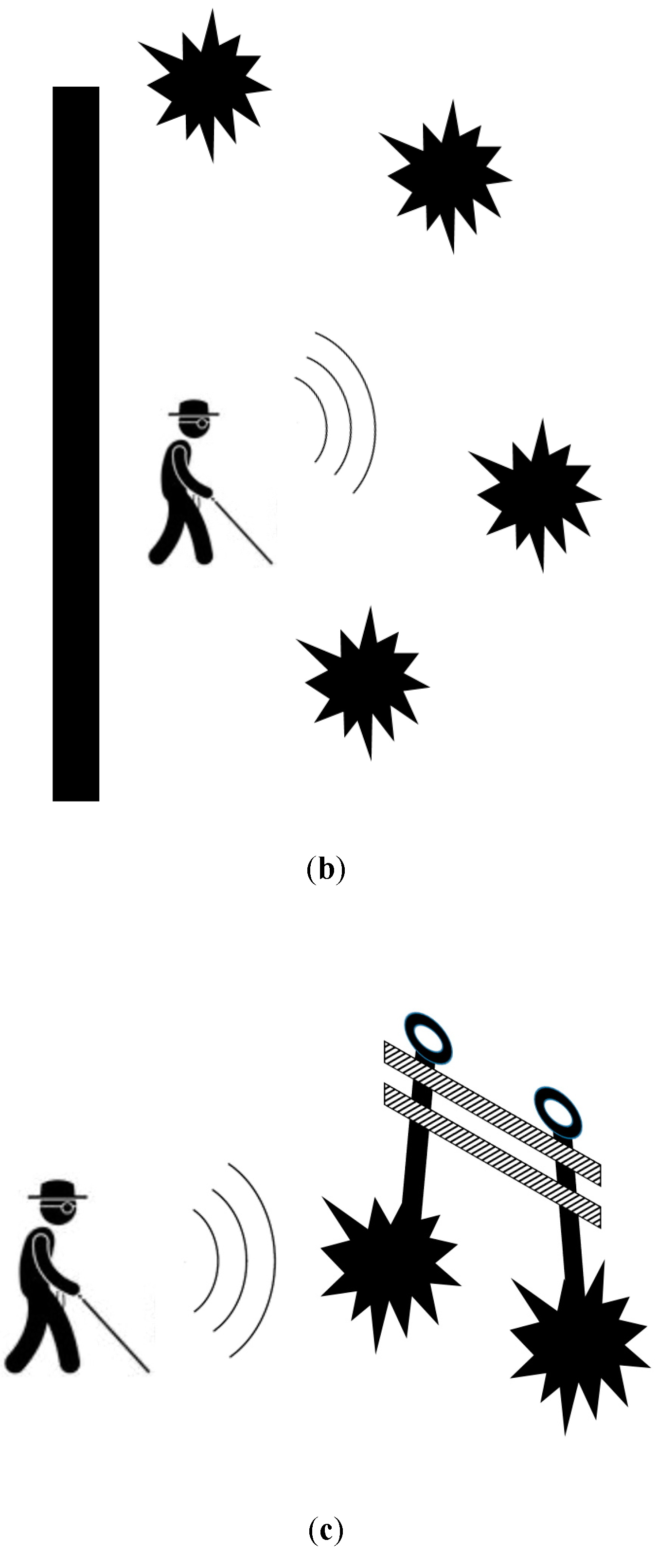
  • The radiation pattern can be tailored by modifying the design of the antennas, thus accurately detecting small apertures or suspended obstacles.
To the best knowledge of the authors, this is the first review article concerning ETAs based on electromagnetic technology. This review is necessary due to the previous lack of a paper that collects and illustrates the main results in this field.
In Section 2, the pertinent studies and prototypes based on the electromagnetic technology are reported. Particular attention is given to the illustration of both practical and technological aspects by clearly explaining the basic modes of operation of the considered aids.
In Section 3, the particular differences between the devices are analyzed providing, in the authors’ opinion, the possible future developments of this technology. Finally, the conclusions are outlined in Section 4.

2. Electromagnetic Aids for Visually Impaired and Blind People

The idea of employing an electromagnetic system as an aid for visually impaired people is quite recent. In [30], a vector network analyzer and a double-ridge horn antenna were used for transmitting and receiving a sequence of pulses from 1 to 6 GHz. Then, an inverse Fourier transform was applied to the frequency-domain measurements in order to recreate a very short time-domain pulse. The measured delay of the received pulse corresponds to the round-trip time-of-flight (TOF) of the electromagnetic wave from the transmitting antenna to the obstacle. Thereafter, the range of the object could be easily computed [31]. The diagram of the system and the echo pulse reflected by a 25 × 25 cm2 metal plate at a distance of 2 m are shown in Figure 1.
The proposed approach was compared with an ultrasonic system, making the two experimental set-ups as equivalent as possible. The proposed system showed better precision and the ability to detect obstacles that are not detectable by ultrasonic systems (e.g., a partially open door). Although the system is very bulky and expensive, its future miniaturization has been claimed.
An enhanced version of the system proposed in [30] has been reported in [32]. A portable vector network analyzer was employed for testing the effectiveness of the methodology in both indoor and outdoor scenarios. The maximum range was fixed to 3 m, whereas the operating frequencies from 4 to 6 GHz achieved a spatial resolution of 12 cm. The tests were carried out by a blind volunteer during different test conditions (i.e., obstacles located in different arrangements). The test set-up was arranged in order to have the obstacles aligned, shaped as a cage, and with an obstacle at chest level—as depicted in Figure 2. The system could correctly detect the presence of one or more obstacles even at the level of the head or chest (e.g., an open window or a tree branch).
A peculiar application of an electromagnetic aid for visually impaired people is reported in [33], where a system capable of guiding a blind athlete during running and physical activities was designed, realized, and tested. This arose from the need to enhance the runners’ freedom during competitions or training. As a matter of fact, athletes currently need to be guided by a non-extendible cable carried by another runner, thus limiting the possibility of free movement [34].
The proposed system is composed of: (a) a mobile unit preceding the runner that generates two “electromagnetic walls” (i.e., two electromagnetic waves radiated on the left and right sides of the athlete) and (b) a receiving unit worn by the runner equipped with vibro-tactile devices.
A representation of the guiding system is shown in Figure 3.
The mobile unit generates a vibro-tactile warning when the athlete is leaving the area delineated by the electromagnetic walls, to guide them towards the center of the path.
In this circumstance, the use of electromagnetic waves ensures confinement of the wall to a narrow and well-defined area. The operating bandwidth of the system is inside the X-band, thus reducing the dimension and weight of the antenna in the receiving unit worn by the blind runner. To achieve this, the antenna was designed with lightweight and compact microstrip technology. The system was tested by a blind athlete using four different paths as reported in Figure 4, demonstrating the proper operation of the prototype. A video of the tests can also be watched online [34].
In [19], the challenge of avoiding collision with obstacles for visually impaired users was achieved by creating a radar-based navigation device. The system employs a frequency-modulated continuous-wave signal. Although the authors plan to have a main sensor working at the center frequency of 80 GHz with a bandwidth of 24 GHz, a bandwidth of 4 GHz—from 80 GHz to 84 GHz—was adopted for the tests. With this frequency bandwidth, a spatial resolution equal to 6 cm can be obtained. The radar sensor was attached on the head of the blind person, whose position was continuously tracked by an inertial sensor. This sensor scanned the surrounding environment and detected the position of obstacles up to 5 m. The intention of the authors is to scan the scenario using a beam-steering antenna. Its design is shown in [19], but since it is still under development, the rotation was mechanically achieved by a stepper motor. Due to the size of the setup, the radar was placed on a large mounting. A virtual map of the environment was created and mapped into a 3D audio signal. The authors assert that a long training process is not required.
A superior system performance compared to camera-based systems is claimed in terms of independence from light conditions, ability to detect transparent obstacles such as glass doors, and better visual range in rain or fog [35,36].
The challenge of tailoring a suitable electromagnetic aid is shown in [20], highlighting the effectiveness of the authors’ solution. A clinical investigation was performed with 25 visually impaired people wearing a radar-based assistive device.
The working frequency of the system was 24 GHz, selected to facilitate a lightweight wearable device, because at this frequency the signal can penetrate textiles, making it possible to wear the device under clothing. The system automatically compensates small tilt errors or notifies the person if the incline is excessive. It is able to detect obstacles up to 3.5 m, within a horizontal sector of 25° and a vertical sector of 70°.
The maximum usage time of the prototype was measured as between 4 and 5 h, but this can be improved in a future designs. The warning about the presence of obstacles is fed back to the user by means of acoustic or haptic feedback. In Figure 5, the operating principle of the system and a picture of the device is shown.
The clinical investigation was implemented during an observation period of two weeks, using the electromagnetic aid during everyday activities.
The results of an interview after usage of the device are shown in Figure 6a in response to the question “Does the assistive device help you to perceive your environment better?”, whereas in Figure 6b the question was “Does the assistive device increase your confidence in independent walking?”.
For both graphs in Figure 6, the answers recorded on the X-axes are: (1) not at all, (2) not much, (3) to some extent, (4) significantly, (5) very significantly.
In the results, 92% of the participants stated that the perception of the surrounding environment was enhanced by the electromagnetic aid, whereas 80% noticed an increased confidence in independent mobility.
Solutions employing 24 GHz radars based on FMCW modulation are presented in [21,22,23], but different choices were made concerning the way the users employ the devices.
Despite the extensive range of available ETAs, the most widespread aid is still the traditional white-cane, due to its ease of use and cost effectiveness [37,38].
Therefore, the authors decided to create a device so small and lightweight that it can be integrated into a white-cane—a kind of “microwave cane”. The authors based their design on feedback from users during interviews and the remarks of visually impaired and blind users, considering the positive reaction to a new device as the main task. Volunteers testing ETAs usually suggest the simultaneous use the white cane.
Since the self-confidence that the traditional white cane is reported to give users is absent in ETAs, the authors chose to go down this route.
Of course, this new device must overcome the limitations of the traditional cane (i.e., it does not provide any protection against obstacles at head or chest height and the range is confined to the length of the cane). At the same time, the system has to be cost effective and easy to use without extensive training.
In [21], great attention is paid to the design of a customized antenna. It was designed by employing microstrip technology in order to have a compact system that can be attached to the cane. They highlight the advantages of the system compared to ones based on ultrasonic or optical technology, overcoming the limitations of limited range and poor performance operating within a low incidence angle on smooth surfaces. The system was tested up to 5 m, with a spatial resolution of 60 cm (24.0–24.25 GHz).
In [22], a feasibility study was undertaken with the aim of accurately identifying the technical specification of the microwave cane. The behavior of the entire system was simulated using computer-aided design (CAD), with preliminary results obtained from newly designed transmitting and receiving antennas. The first experimental activity using the microwave cane is outlined in [23].
The authors obtained system spatial resolution close to 14 cm, reduced energy consumption, a maximum range of 5 m, and horizontal and vertical antenna patterns close to 12° and 40°, respectively.
A picture of the prototype is shown in Figure 7.
The radar system was tested with different obstacles commonly used for daily tasks, that is, a wooden chair, a chest of drawers, and a human subject. The targets, characterized by different materials, dimensions, and shapes, were located at the range of 1.5 m and successfully detected, as shown in Figure 8.
An interesting solution is illustrated in [24,25], where the radar technology was employed in conjunction with an RGB-D sensor. The radar operated from 77 to 81 GHz, implementing an FMCW signal. This 4 GHz bandwidth gives a spatial resolution of 6 cm. The purpose of the exercise was to enhance the features of object detection and localization. Whereas mm-wave radar is capable of providing speed information and a relatively high spatial resolution in the radial direction, the RGB-D sensor accomplishes the task of distinguishing two targets at the same distance. A block diagram of the system is shown in Figure 9.
Obstacles at the same distance are recognized using color information and the application of a single deep neural network or object instance segmentation [39,40].
In Figure 10, results relating to tests performed in an indoor environment are shown. In Figure 10(a1,a2) the mask R-CNN (Region convolutional neural network) was used for detecting and recognizing the targets, whereas in (b1,b2) the SSD (Single Shot MultiBox Detector ) network was used. In (c1,c2) the image results are shown with, detection results enclosed in a red box, whereas in (d1,d2) the data detected by the radar are illustrated. Finally, in (e1,e2), the data are fused using a particle filter.
The potential of this technology is also highlighted by the Integrated Smart Spatial Exploration System (INSPEX H2020 project), where the main goal is to take advantage of the automotive techniques concerning spatial exploration and obstacle detection in the design of portable sensors [41]. Potential applications employing radar-based sensors range from safer human navigation in reduced visibility to navigation for visually impaired people. The authors intend to integrate the INSPEX system into a smart white cane.

3. Discussion

In Section 2, the main contributions in the field were reported, showing properties of the proposed systems such as working principle, maximum range, cost, size, spatial resolution, operating frequency, and the existence of a final prototype. These aspects are organized in Table 1.
By analyzing the properties shown in Table 1, we can conclude that different devices could be market ready very quickly, which would provide useful products that could offer a good compromise between the capability of scanning the environment, cost-effectiveness, and size.
Therefore, it is legitimate to ask why there is still no valid electromagnetic aid available on the market. We believe that it can be explained by the fact that there is insufficient collaboration between research groups and industry, which would provide a more effective transition from laboratory prototypes to the final engineered product. Indeed, since the core technology is based on radar, the necessary components, used by the relevant advancement in the automotive field, are readily available for use Moreover, the miniaturization of the operating frequencies in a typical of microwave and millimeter waves could be utilized to minimize size and weight, affording easy integration in everyday activities.
Although the electromagnetic aids exhibit better performance than ultrasonic or camera-based solutions, recent years have seen these technologies more broadly diffused due to their wider availability in the market. Moreover, in published papers only limited attention has been given to finding the best solution for providing feedback to the user. A greater effort in this direction could be very beneficial for enhancing the usability of this category of travel aid.

4. Conclusions

In this review, the most recent developments relating to electromagnetic travel aids for visually impaired and blind people are presented. The main contributions in the field were analyzed, highlighting the working principle, the impact on the end user’s life, and the main properties. The presented solutions mostly employ radar-based devices, with only one system exploiting a (vector network analyzer) VNA-based technology. Overall, the trend is towards employing ever-higher operation frequencies in order to realize compact systems and to increase the resolution capabilities. The electromagnetic technology shows better performance than other types of electronic travel aid, as they have a more reliable signal processing technique, smaller dimensions, higher precision and resolution, and better immunity to noise. Although the “perfect” aid has not yet been realized, this contribution highlights that the technology is mature and different solutions can be adopted for fulfilling this challenging task.

Author Contributions

E.C. collected the required bibliography and wrote the review article. A.C. supervised the research activities and revised the paper.

Funding

This research received no external funding.

Conflicts of Interest

The authors declare no conflict of interest.

References

  1. Bourne, R.R.A.; Flaxman, S.R.; Braithwaite, T.; Cicinelli, M.V.; Das, A.; Jonas, J.B.; Keeffe, J.; Kempen, J.H.; Leasher, J.; Limburg, H.; et al. Magnitude, temporal trends, and projections of the global prevalence of blindness and distance and near vision impairment: A systematic review and meta–analysis. Lancet Glob. Health 2017, 5, 888–897. [Google Scholar] [CrossRef]
  2. Corcoran, C.; Douglas, G.; Pavey, S.; Fielding, A.; McCall, S.; McLinden, M. Network 1000: The changing needs and circumstances of visually impaired people: A project overview. Br. J. Vis. Impair. 2004, 22, 93–100. [Google Scholar] [CrossRef]
  3. Velazquez, R. Wearable assistive devices for the blind. In Wearable and Autonomous Biomedical Devices and Systems for Smart Environment; Lecture Notes in Electrical Engineering; Springer International Publishing: New York, NY, USA, 2010; Volume 75, pp. 331–349. [Google Scholar]
  4. Paiva, S. Technological Trends in Improved Mobility of the Visually Impaired, 1st ed.; Springer International Publishing: New York, NY, USA, 2020. [Google Scholar]
  5. Islam, M.M.; Sadi, M.S.; Zamli, K.Z.; Ahmed, M.M. Developing walking assistants for visually impaired people: A review. IEEE Sens. J. 2019, 19, 2814–2828. [Google Scholar] [CrossRef]
  6. Bai, J.; Liu, Z.; Lin, Y.; Li, Y.; Lian, S.; Liu, D. Wearable travel aid for environment perception and navigation of visually impaired people. Electronics 2019, 8, 697. [Google Scholar] [CrossRef]
  7. Blasch, B.B.; Wiener, W.R.; Welsh, R.L. Foundations of Orientation and Mobility, 3nd ed.; AFB Press: New York, NY, USA, 2010. [Google Scholar]
  8. National Research Council. Electronic Travel Aids: New Directions for Research; Nat. Acad. Press: Washington, DC, USA, 1986. [Google Scholar]
  9. Roentgen, U.R.; Gelderblom, G.J.; Soede, M.; De Witte, L. Inventory of electronic mobility aids for visually impaired persons—A literature review. J. Vis. Impair. Blind. 2008, 102, 702–724. [Google Scholar] [CrossRef]
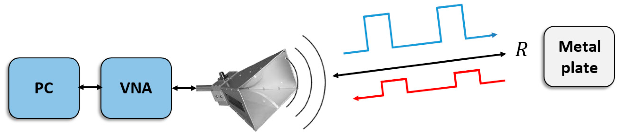
  10. Di Mattia, V.; Scalise, L.; Petrini, V.; Russo, P.; De Leo, A.; Pallotta, E.; Mancini, A.; Zingaretti, P.; Cerri, G. Electromagnetic technology for a new class of electronic travel aids supporting the autonomous mobility of visually impaired people. Sensors 2017, 17, 364. [Google Scholar]
  11. Patil, K.; Jawadwala, Q.; Shu, F.C. Design and construction of electronic aid for visually impaired people. IEEE Trans. Hum. Mach. Syst. 2018, 48, 172–182. [Google Scholar] [CrossRef]
  12. Zhou, D.; Yang, Y.; Yan, H. A smart ‘virtual eye’ mobile system for the visually impaired. IEEE Potentials 2016, 35, 13–20. [Google Scholar] [CrossRef]
  13. Sohl–Dickstein, J.; Teng, S.; Gaub, B.M.; Rodgers, C.C.; Li, C.; DeWeese, M.R.; Harper, N.S. A device for human ultrasonic echolocation. IEEE Trans. Biomed. Eng. 2015, 62, 1526–1534. [Google Scholar] [CrossRef]
  14. Bhatlawande, S.; Mahadevappa, M.; Mukherjee, J.; Biswas, M.; Das, D.; Gupta, S. Design, development, and clinical evaluation of the electronic mobility cane for vision rehabilitation. IEEE Trans. Neural Syst. Rehabil. Eng. 2014, 22, 1148–1159. [Google Scholar] [CrossRef]
  15. Bai, J.; Lian, S.; Liu, Z.; Wang, K.; Liu, D. Virtual–blind–road following–based wearable navigation device for blind people. IEEE Trans. Consum. Electron. 2018, 64, 136–143. [Google Scholar] [CrossRef]
  16. Kang, M.-C.; Chae, S.-H.; Sun, J.-Y.; Lee, S.-H.; Ko, S.-J. An enhanced obstacle avoidance method for the visually impaired using deformable grid. IEEE Trans. Consum. Electron. 2017, 63, 169–177. [Google Scholar] [CrossRef]
  17. Yang, K.; Wang, K.; Hu, W.; Bai, J. Expanding the detection of traversable area with realsense for the visually impaired. Sensors 2016, 10, 1954. [Google Scholar] [CrossRef] [PubMed]
  18. Cardillo, E.; Caddemi, A. Feasibility study to preserve the health of an Industry 4.0 worker: A Radar System for Monitoring the Sitting-Time. In Proceedings of the IEEE International Workshop on Metrology for Industry 4.0 and IoT, Naples, Italy, 4–6 June 2019. [Google Scholar]
  19. Kwiatkowski, P.; Jaeschke, T.; Starke, D.; Piotrowsky, L.; Deis, H.; Pohl, N. A Concept Study for a Radar-Based Navigation Device with Sector Scan Antenna for Visually Impaired People. In Proceedings of the IEEE MTT–S International Microwave Bio Conference (IMBIOC), Gothenburg, Sweden, 15–17 May 2017. [Google Scholar]
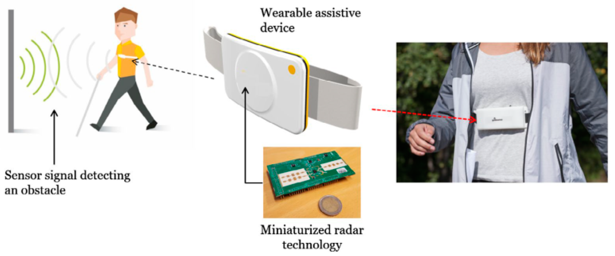
  20. Kiuru, T.; Metso, M.; Utriainen, M.; Metsavainio, K.; Jauhonen, H.M.; Rajala, R.; Savenius, R.; Strom, M.; Jylha, T.N.; Juntunen, R.; et al. Assistive device for orientation and mobility of the visually impaired based on millimeter wave radar technology—Clinical investigation results. Cogent Eng. 2018, 5, 1–12. [Google Scholar] [CrossRef]
  21. Pisa, S.; Pittella, E.; Piuzzi, E. Serial patch array antenna for an FMCW radar housed in a white cane. Int. J. Antennas Propag. 2016, 2016, 9458609. [Google Scholar] [CrossRef]
  22. Di Mattia, V.; Manfredi, G.; De Leo, A.; Russo, P.; Scalise, L.; Cerri, G.; Caddemi, A.; Cardillo, E. A Feasibility Study of a Compact Radar System for Autonomous Walking of Blind People. In Proceedings of the International Forum on Research and Technologies for Society and Industry Leveraging a Better Tomorrow (RTSI), Bologna, Italy, 7–9 September 2016. [Google Scholar]
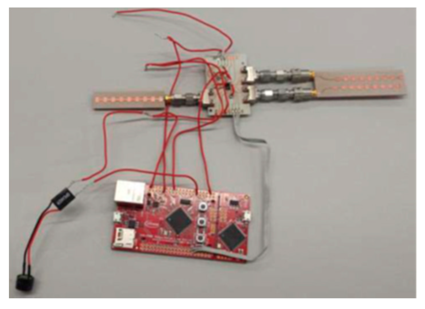
  23. Cardillo, E.; Di Mattia, V.; Manfredi, G.; Russo, P.; De Leo, A.; Caddemi, A.; Cerri, G. An electromagnetic sensor prototype to assist visually impaired and blind people in autonomous walking. IEEE Sens. J. 2018, 18, 2568–2576. [Google Scholar] [CrossRef]
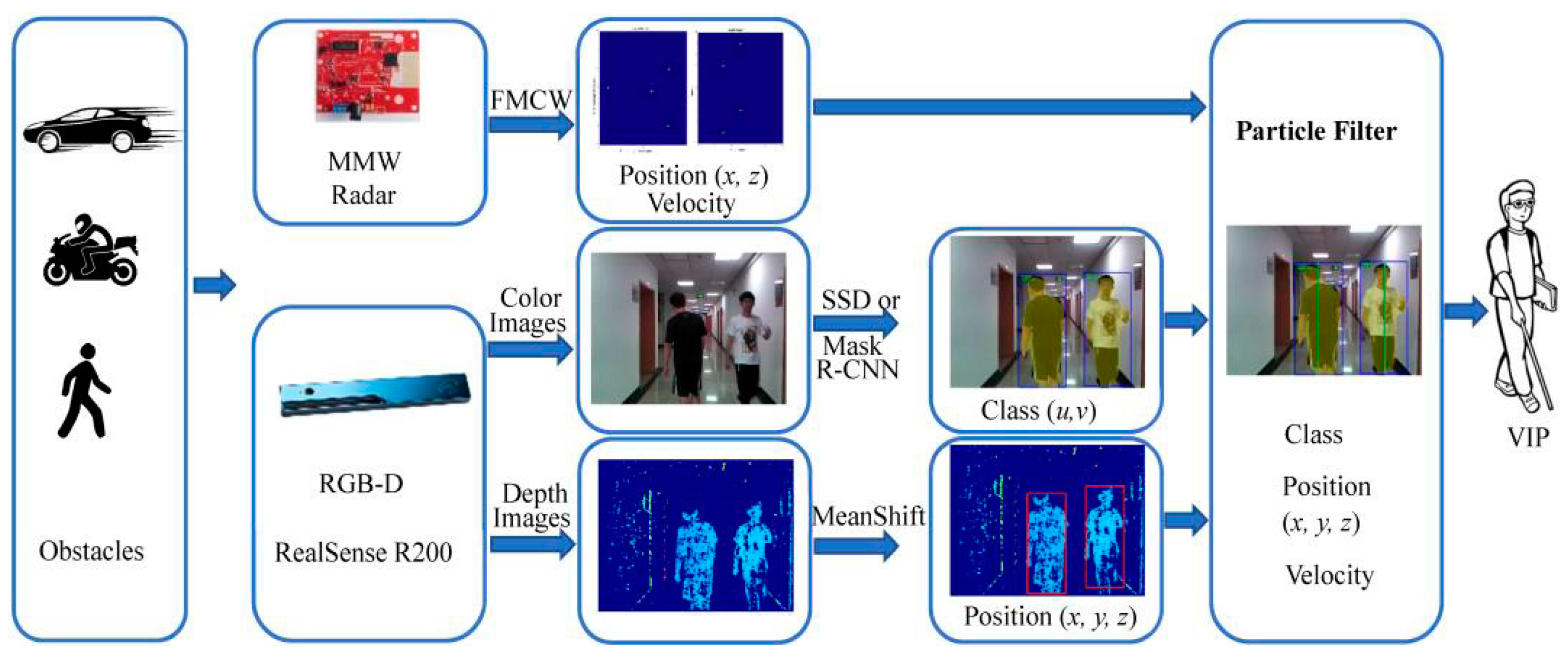
  24. Long, N.; Wang, K.; Cheng, R.; Hu, W.; Yang, K. Unifying obstacle detection, recognition, and fusion based on millimeter wave radar and RGB–depth sensors for the visually impaired. Rev. Sci. Instrum. 2019, 90, 1–12. [Google Scholar] [CrossRef]
  25. Long, N.; Wang, K.; Cheng, R.; Yang, K.; Hu, W.; Bai, J. Assisting the visually impaired: Multitarget warning through millimeter wave radar and RGB–depth sensors. J. Electron. Imag. 2019, 28, 1–15. [Google Scholar] [CrossRef]
  26. Cardillo, E.; Caddemi, A. A novel approach for crosstalk minimization in FMCW radars. Electron. Lett. 2017, 53, 1379–1381. [Google Scholar] [CrossRef]
  27. Caddemi, A.; Cardillo, E. A Study on Dynamic Threshold for the Crosstalk Reduction in Frequency-Modulated Radars. In Proceedings of the Computing and Electromagnetics International Workshop (CEM), Barcelona, Spain, 21–24 June 2017. [Google Scholar]
  28. Pozar, D.M. Microwave Engineering, 4th ed.; John Wiley & Sons, Inc.: Hoboken, NJ, USA, 2011. [Google Scholar]
  29. Caddemi, A.; Cardillo, E. A low-cost smart microwave radar for short range measurements. In International Conference on Applications in Electronics Pervading Industry, Environment and Society; Springer International Publishing: New York, NY, USA, 2018; Volume 512, pp. 41–47. [Google Scholar]
  30. Scalise, L.; Mariani Primiani, V.; Russo, P.; Shahu, D.; Di Mattia, V.; De Leo, A.; Cerri, G. Experimental investigation of electromagnetic obstacle detection for visually impaired users: A comparison with ultrasonic sensing. IEEE Trans. Instrum. Meas. 2012, 61, 3047–3057. [Google Scholar] [CrossRef]
  31. Richards, M.A.; Scheer, J.A.; Holm, W.A. Principles of Modern Radar: Basic Principle; SciTech Publishing: Atlanta, GA, USA, 2010. [Google Scholar]
  32. Di Mattia, V.; Russo, P.; De Leo, A.; Mariani Primiani, V.; Petrini, V.; Cerri, G.; Scalise, L. An electromagnetic device for autonomous mobility of visually impaired people. In Proceedings of the European Microwave Conference, Rome, Italy, 6–9 October 2014. [Google Scholar]
  33. Pieralisi, M.; Petrini, V.; Di Mattia, V.; Manfredi, G.; De Leo, A.; Scalise, L.; Russo, P.; Cerri, G. Design and realization of an electromagnetic guiding system for blind running athletes. Sensors 2015, 15, 16466–16483. [Google Scholar] [CrossRef] [PubMed]
  34. EM System to Guide Visually Impaired Running Athletes. Available online: https://www.youtube.com/watch?v=GIyQDu0nOww (accessed on 30 September 2019).
  35. Hicks, S.L.; Wilson, I.; Van Rheede, J.J. Improved mobility with depth–based residual vision glasses. Invest. Ophthalmol. Vis. Sci. 2014, 55, 2153. [Google Scholar]
  36. Grant, P.; Spencer, L.; Arnoldussen, A. The Functional Performance of the BrainPort V100 Device in Persons Who Are Profoundly Blind. J. Vis. Impair. Blind. 2016, 110, 77–88. [Google Scholar] [CrossRef]
  37. Hersh, M.; Johnson, M.A. Assistive Technology for Visually Impaired and Blind People; Springer: London, UK, 2008. [Google Scholar]
  38. Dakopoulos, D.; Bourbakis, N.G. Wearable Obstacle Avoidance Electronic Travel Aids for Blind: A Survey. IEEE Trans. Syst. Man Cybern. Part C Appl. Rev. 2009, 40, 25–35. [Google Scholar] [CrossRef]
  39. Liu, W.; Anguelov, D.; Erhan, D.; Szegedy, C.; Reed, S.; Fu, C.Y.; Berg, A.C. SSD: Single Shot MultiBox Detector. In ECCV 2016: Computer Vision—ECCV 2016; Lecture Notes in Computer Science; Springer International Publishing: New York, NY, USA, 2016; Volume 9905, pp. 21–37. [Google Scholar]
  40. He, K.; Gkioxari, G.; Dollar, P.; Girshick, R. Mask R-CNN. In Proceedings of the IEEE International Conference on Computer Vision, Venice, Italy, 22–29 October 2017. [Google Scholar]
  41. Lesecq, S.; Foucault, J.; Birot, F.; De Chaumont, H.; Jackson, C.; Correvon, M.; Heck, P.; Banach, R.; Di Matteo, A.; Di Palma, V.; et al. INSPEX: Design and integration of a portable/wearable smart spatial exploration system. In Proceedings of the 2017 Design, Automation & Test in Europe Conference & Exhibition, Lausanne, Switzerland, 27–31 March 2017. [Google Scholar]
Figure 1. Diagram of the system.
Electronics 08 01281 g001
Figure 2. Test set-up with (a) aligned obstacles, (b) obstacles shaped as a cage, and (c) obstacles at chest level.
Electronics 08 01281 g002aElectronics 08 01281 g002b
Figure 3. Representation of the guiding system [33].
Electronics 08 01281 g003
Figure 4. Paths traveled by the athlete in a rectangular room (20 × 17 m2): (a) square, (b) spiral, and (c,d) complex paths [33].
Electronics 08 01281 g004
Figure 5. Operating principle of the system and picture of the device [20].
Electronics 08 01281 g005
Figure 6. Results of the interview questions: (a) “Does the assistive device help you to perceive your environment better?” and (b) “Does the assistive device increase your confidence in independent walking?” The answers reported on the X-axes are: (1) not at all, (2) not much, (3) to some extent, (4) significantly, (5) very significantly [20].
Electronics 08 01281 g006
Figure 7. Picture of the radar prototype [23].
Electronics 08 01281 g007
Figure 8. Intermediate frequency (IF) signals obtained from obstacles at the range of 1.5 m. From the top to bottom, results are shown for a wooden chair, a chest of drawers, and a human target [23].
Electronics 08 01281 g008
Figure 9. Schematic diagram of the system in [24]. FMCW: frequency-modulated continuous wave.
Electronics 08 01281 g009
Figure 10. Tests performed in an indoor environment and related results [24]. (a1,a2) Detection performed by R-CNN, (b1,b2) detection performed by SSD network, (c1,c2) image results, (d1,d2) data detected by the radar, (e1,e2), data fused using a particle filter.
Electronics 08 01281 g010
Table 1. Properties of the main electromagnetic aids for visually impaired people.
Ref.Working PrincipleMaximum Range (m)CostSizeSpatial Resolution (cm)Operating Frequency (GHz)Final Prototype
[32]VNA-based3HighBulky124.0–6.0No
[19]Radar5MediumBulky680.0–84.0No
[20]Radar3.5LowSmallND24.0No
[21]Radar5LowSmall6024.0–24.25No
[23]Radar5LowSmall1424.0–25.1No
[24]Radar + RGB12LowMedium677.0–81.0No

