Measurement of the PMSM Shaft Position with An Absolute Encoder


Abstract
:1. Introduction
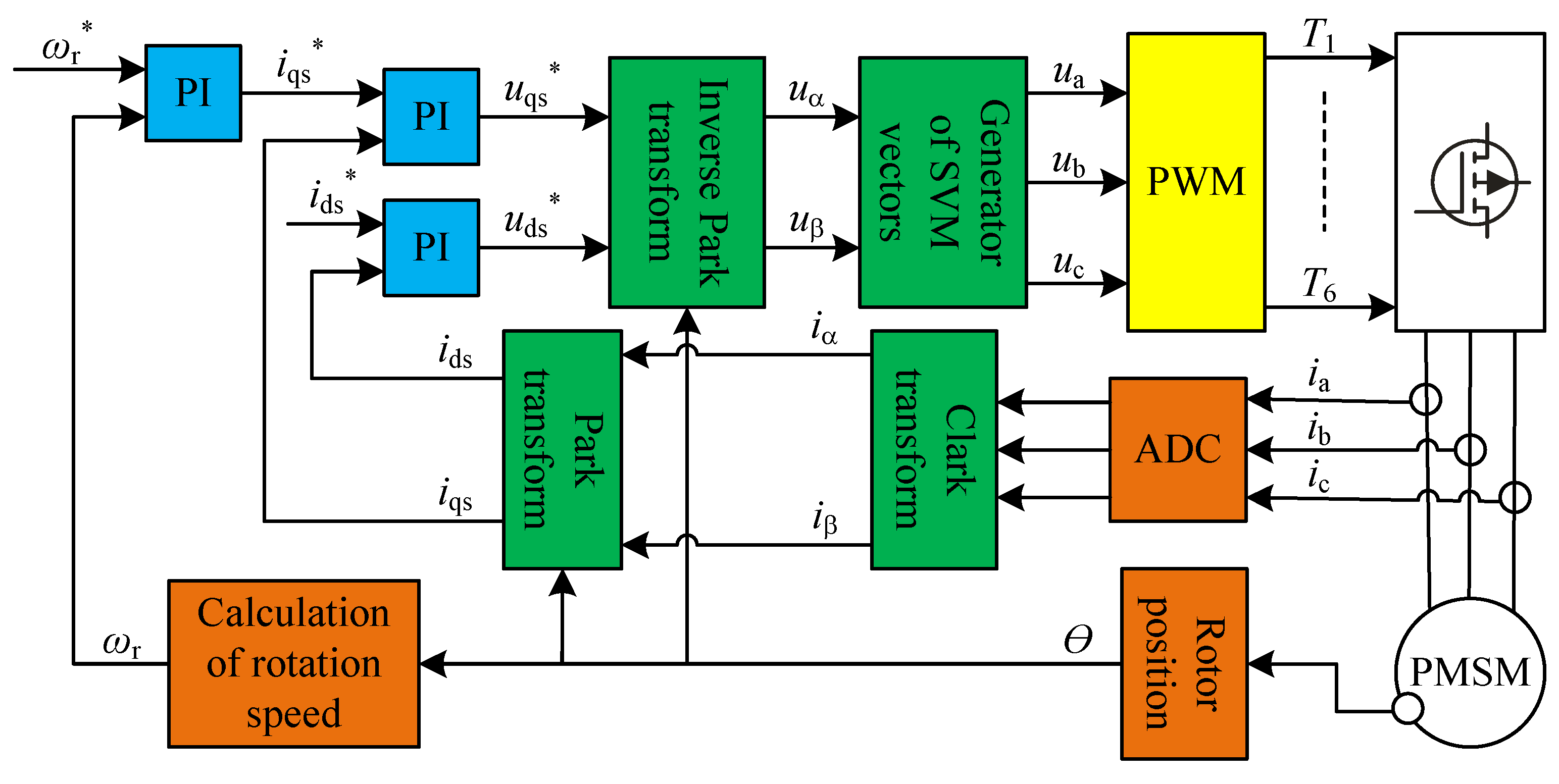
2. Control Unit for PMSM
- Performing complex mathematical calculations;
- high computing performance;
- appropriate hardware resources, e.g., input/output (I/O) ports, counters, PWM modulator, ADC, serial bus;
- dedication to control three-phase motors.
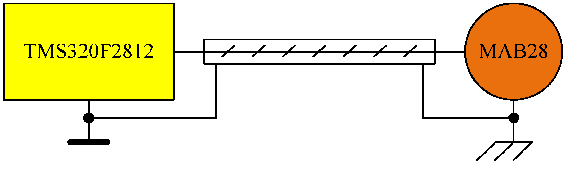
- Small dimensions;
- 12-bit resolution;
- +5 V supply voltage;
- electrically erasable programmable read-only memory (EEPROM);
- serial bus.
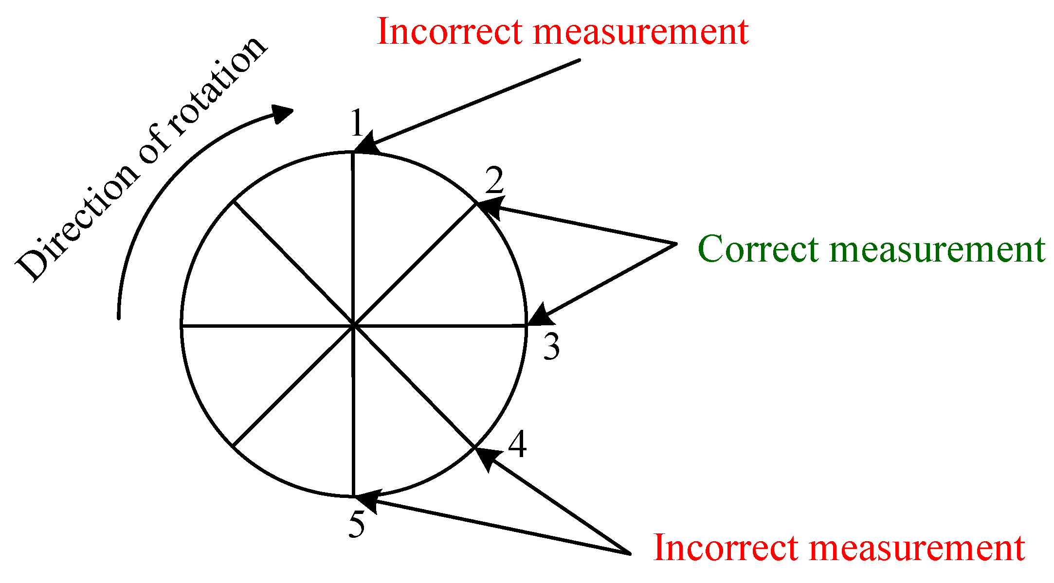
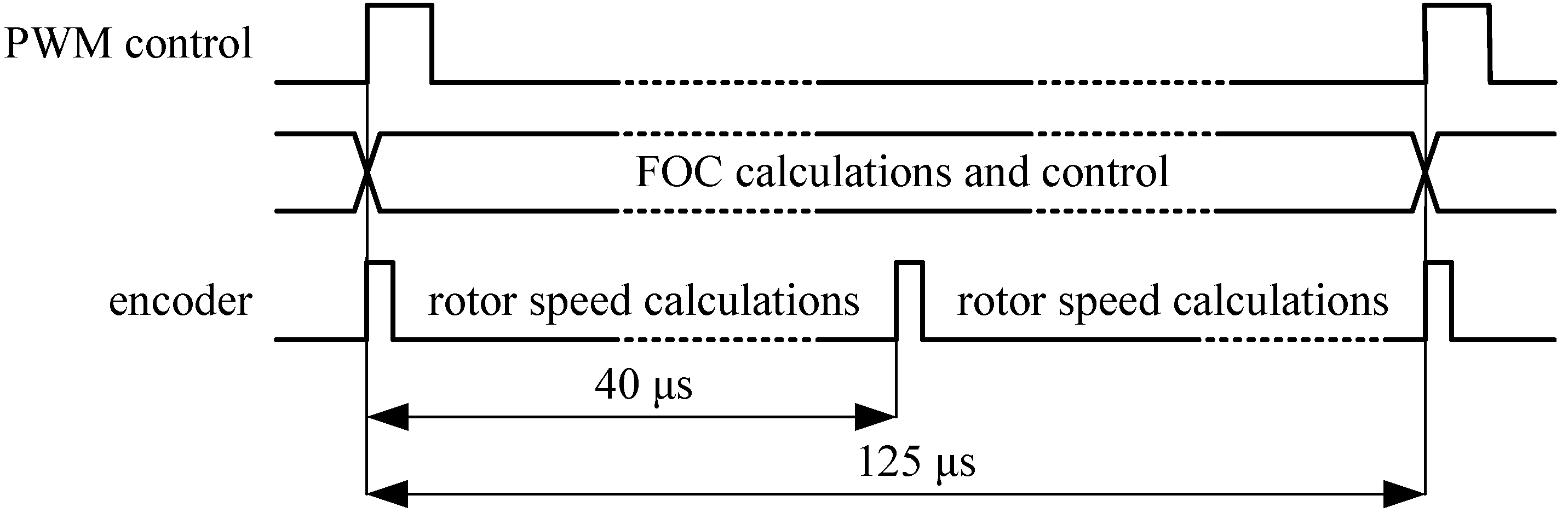
- Reading in the fixed time interval trpm of two motor shaft positions (position1, position2);
- calculation of the obtained geometric angle increment in time unit per rotational speed.
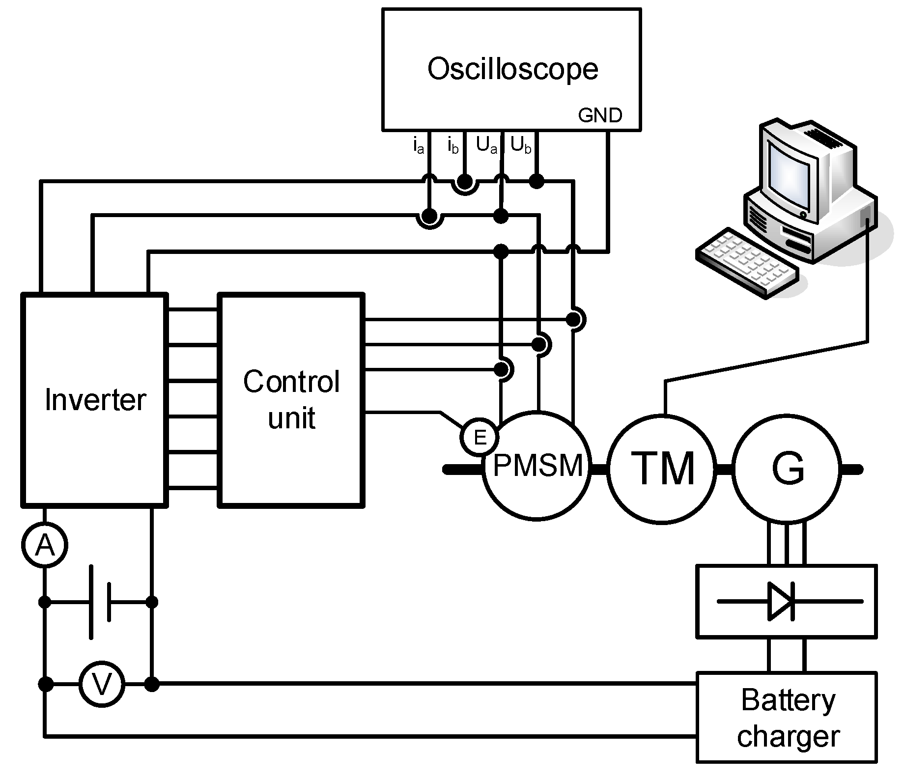
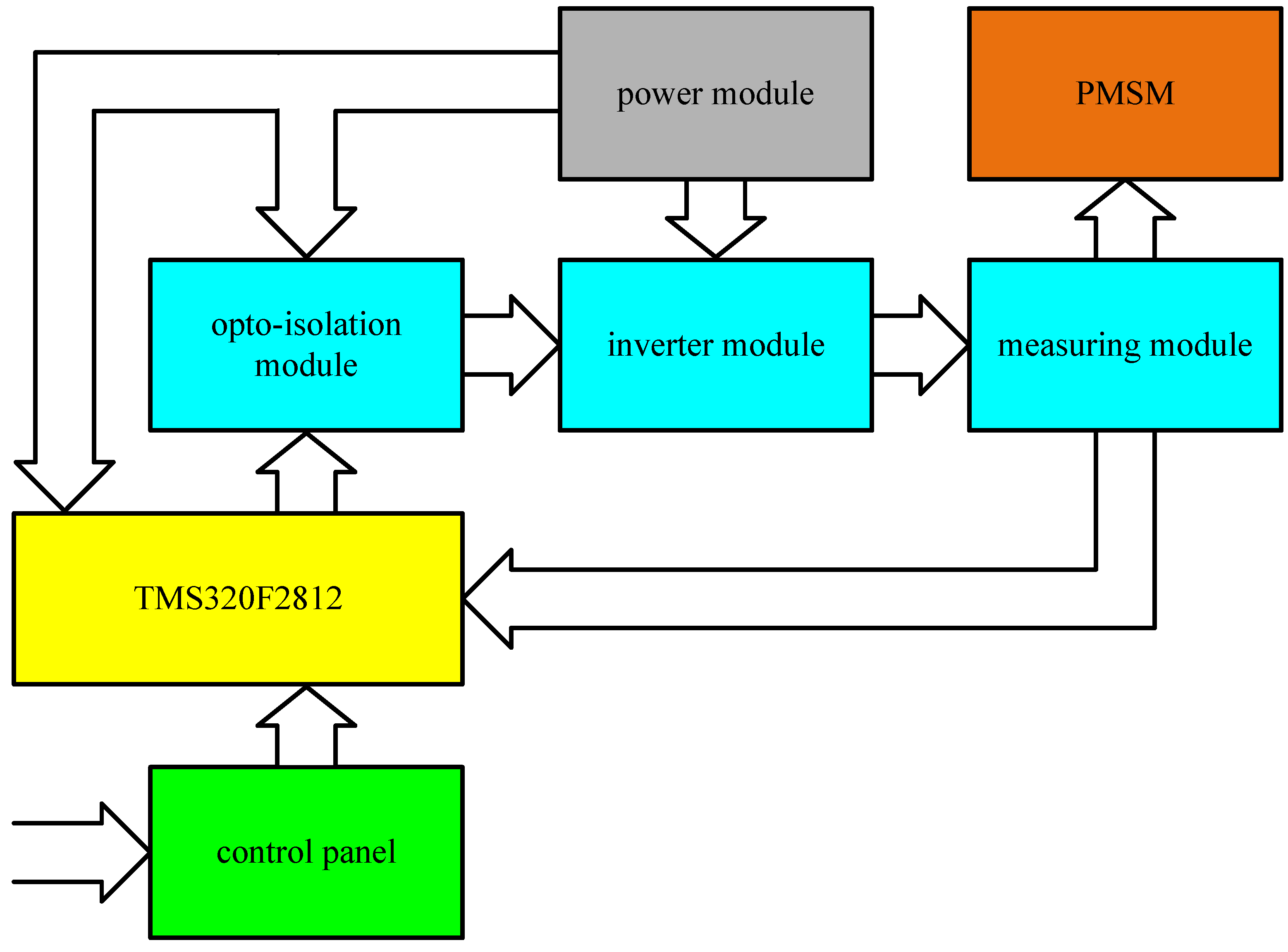
3. Materials and Methods
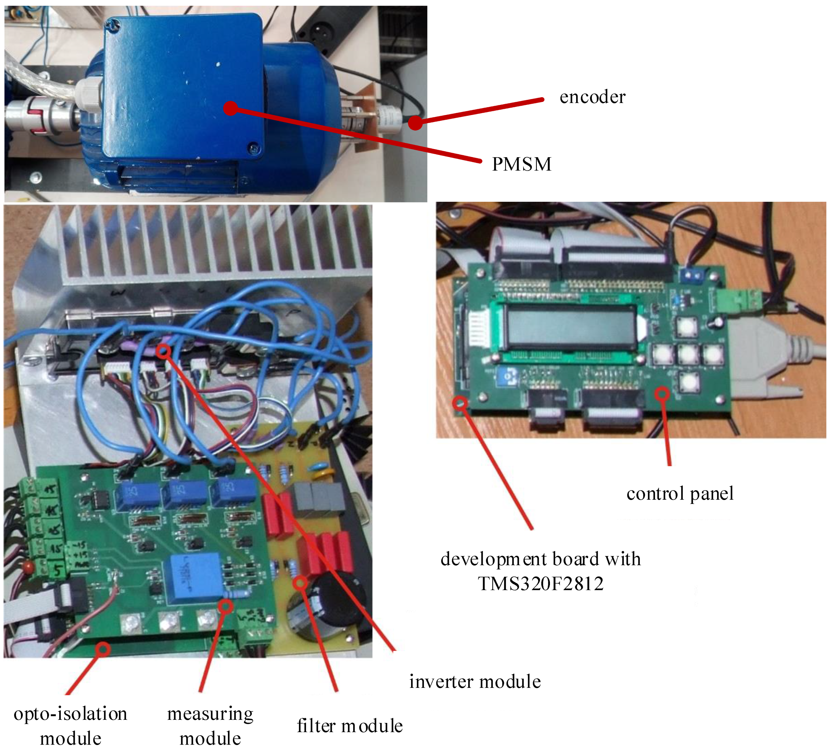
- Control panel;
- development board with TMS320F2812;
- opto-isolation module;
- inverter module;
- measuring module;
- power module.
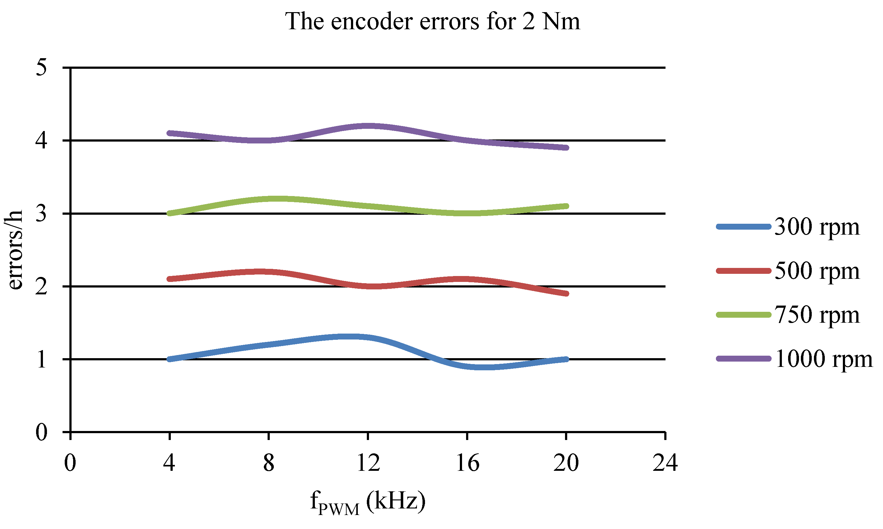
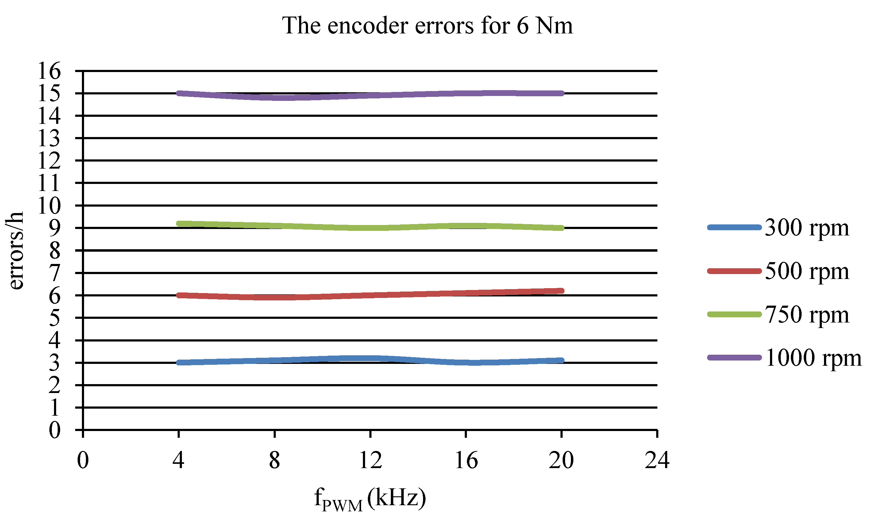
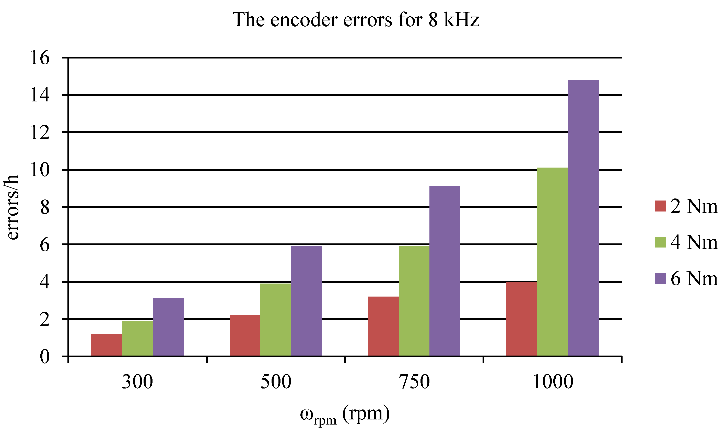
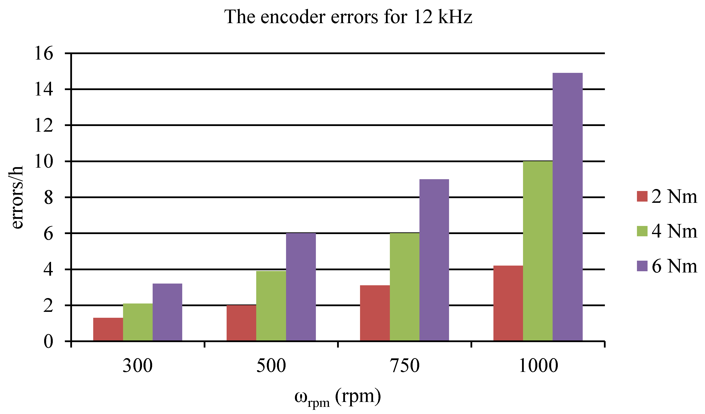
4. Results
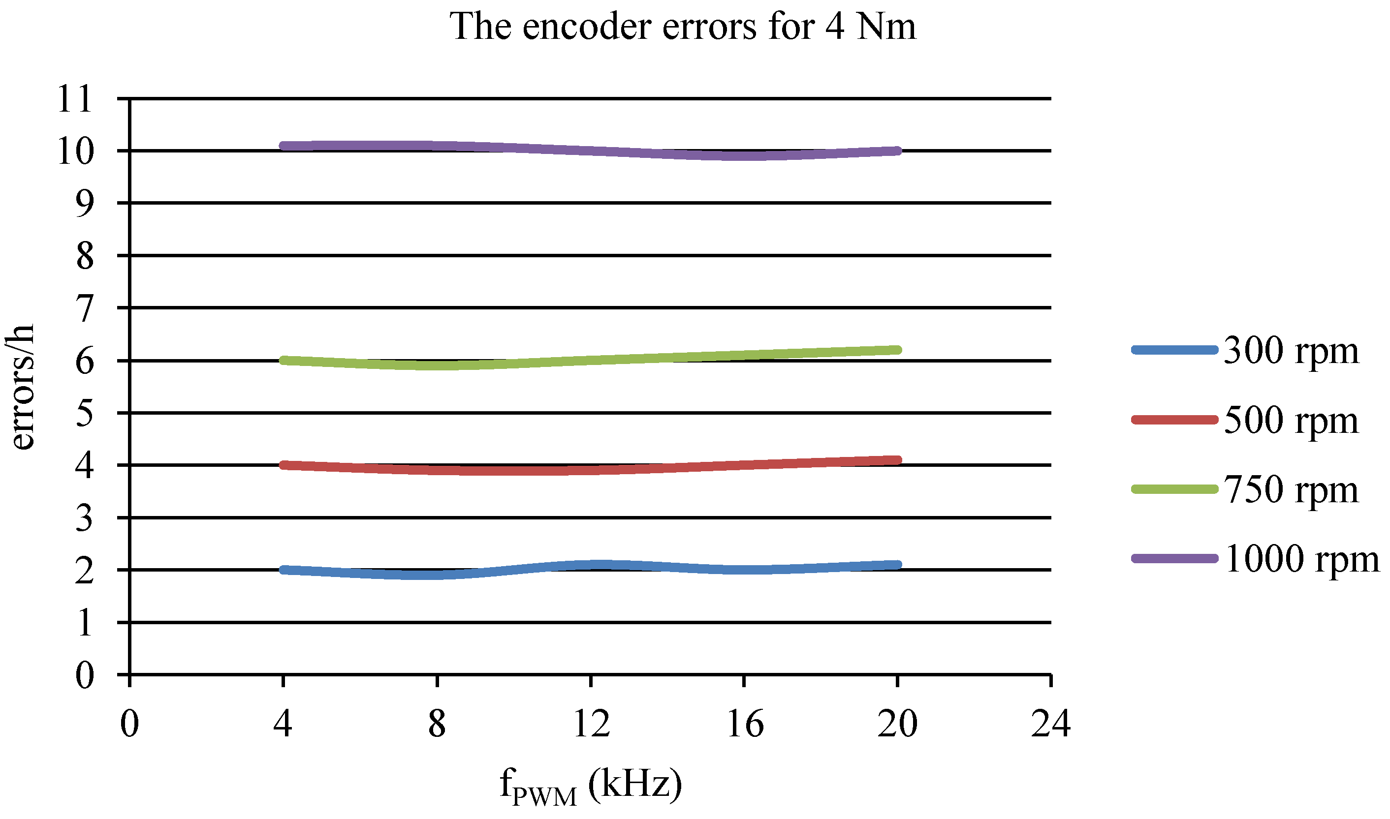
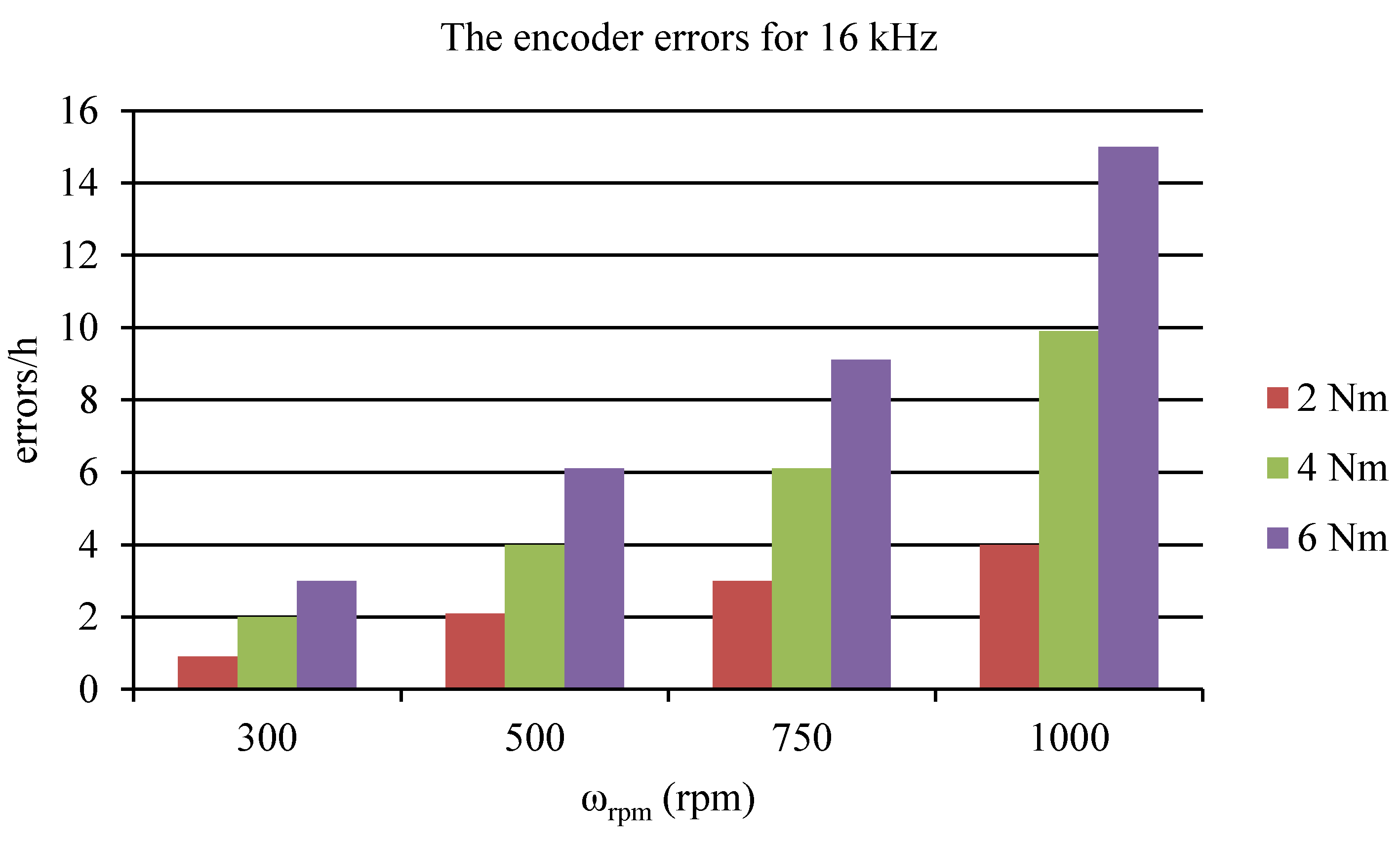
- The PWM control frequency for the motor in the range of 4–20 kHz with increments of 4 kHz;
- the rotation speed for the motor at 300, 500, 750, and 1000 rpm;
- the load torque for the motor at 2, 4, and 6 Nm.
5. Discussion
6. Conclusions
Author Contributions
Funding
Conflicts of Interest
References
- Pillay, P.; Krishnan, R. Modeling, simulation, and analysis of permanent-magnet motor-drives. I. The permanent-magnet synchronous motor drive. IEEE Trans. Ind. Appl. 1989, 25, 265–273. [Google Scholar] [CrossRef]
- Czerwinski, R.; Rudnicki, T. Examination of electromagnetic noises and practical operations of a PMSM motor driven by a DSP and controlled by means of field oriented control. Elektron. ir Elektrotechnika 2014, 20, 46–50. [Google Scholar] [CrossRef]
- Rudnicki, T.; Sikora, A.; Czerwinski, R.; Glinka, T. Impact of PWM control frequency on efficiency of drive with 1 kW permanent magnet synchronous motor. COMPEL Int. J. Comput. Math. Electr. Electron. Eng. 2018, 37, 307–318. [Google Scholar] [CrossRef]
- Bourogaoui, M.; Jlassi, I.; Khojet El Khil, S.; Ben Attia Sethom, H. An effective encoder fault detection in PMSM drives at different speed ranges. In Proceedings of the IEEE 10th International Symposium on Diagnostics for Electrical Machines, Guarda, Portugal, 1–4 September 2015. [Google Scholar]
- Kumar, P.; Kaushik, N.; Dahiya, S. Simulation of sensor less speed control of PMSM based on FOC method with MRAS adaptive speed estimator. In Proceedings of the 2013 Annual IEEE India Conference, Mumbai, India, 13–15 December 2013. [Google Scholar]
- Kamel, T.; Abdelkader, D.; Said, B.; Padmanaban, S.; Iqbal, A. Extended Kalman Filter Based Sliding Mode Control of Parallel-Connected Two Five-Phase PMSM Drive System. Electronics 2018, 7, 14. [Google Scholar] [CrossRef]
- Chen, G.; Yang, S.; Hsu, Y.; Li, K. Position and Speed Estimation of Permanent Magnet Machine Sensorless Drive at High Speed Using an Improved Phase-Locked Loop. Energies 2017, 10, 1571. [Google Scholar] [CrossRef]
- Wuri Harini, B.; Subiantoro, A.; Yusivar, F. Study of speed sensorless permanent magnet synchronous motor (PMSM) control problem due to braking during steady state condition. In Proceedings of the 2017 International Symposium on Electrical and Computer Engineering, Nusa Dua, Indonesia, 24–27 July 2017. [Google Scholar]
- Sun, P.; Ge, Q.; Zhang, B.; Wang, X. Sensorless Control Technique of PMSM Based on RLS On-Line Parameter Identification. In Proceedings of the 2018 International Conference on Electrical Machines and Systems, Jeju, Korea, 7–10 October 2018. [Google Scholar]
- Hind, D.; Li, C.; Sumner, M.; Gerada, C. Realising robust low speed sensorless PMSM control using current derivatives obtained from standard current sensors. In Proceedings of the 2017 IEEE International Electric Machines and Drives Conference, Miami, FL, USA, 21–24 May 2017. [Google Scholar]
- Kim, H.; Son, J.; Lee, J. A High-Speed Sliding-Mode Observer for the Sensorless Speed Control of a PMSM. IEEE Trans. Ind. Electron. 2011, 58, 4069–4077. [Google Scholar]
- Verrelli, C.; Bifaretti, S.; Carfagna, E.; Lidozzi, A.; Solero, L.; Crescimbini, F.; Di Benedetto, M. Speed Sensor Fault Tolerant PMSM Machines: From Position-Sensorless to Sensorless Control. IEEE Trans. Ind. Appl. 2019, 55, 3946–3954. [Google Scholar] [CrossRef]
- Singh, S.; Tiwari, A.N.; Singh, S.N. Performance of Sensorless Method for PMSM Drive. In Proceedings of the 2018 IEEE India International Conference on Power Electronics, Jaipur, India, 13–15 December 2018. [Google Scholar]
- Zhou, H.; Kuang, M.; Wu, J. A rotor position and speed estimation method for sensorless control of permanent magnetic synchronous motor. In Proceedings of the 2012 IEEE International Symposium on Power Electronics for Distributed Generation Systems, Aalborg, Denmark, 25–28 June 2012. [Google Scholar]
- Sensored Field Oriented Control of 3-Phase Permanent Magnet Synchronous Motors Using TMS320F2837x. Available online: http://www.ti.com/lit/an/sprabz0/sprabz0.pdf (accessed on 20 June 2016).
- Rudnicki, T.; Sikora, A.; Czerwinski, R.; Polok, D. Impact of PWM Control Frequency onto Efficiency of a 1 kW Permanent Magnet Synchronous Motor. Elektron. ir Elektrotechnika 2016, 22, 10–16. [Google Scholar] [CrossRef]
- Berriri, H.; Naouar, M.W.; Slama-Belkhodja, I. Easy and Fast Sensor Fault Detection and Isolation Algorithm for Electrical Drives. IEEE Trans. Power Electron. 2012, 27, 490–499. [Google Scholar] [CrossRef]
- Ramakrishnan, R.; Gebregergis, A.; Islam, M. Effect of Position Sensor Error on the Performance of PMSM Drives for Low Torque Ripple Applications. In Proceedings of the IEEE International Electric Machines and Drives Conference, Chicago, IL, USA, 12–15 May 2013; pp. 1166–1173. [Google Scholar]
- Wu, S.T.; Chen, J.Y.; Wu, S.H. A Rotary Encoder With an Eccentrically Mounted Ring Magnet. IEEE Trans. Instrum. Meas. 2014, 63, 1907–1915. [Google Scholar] [CrossRef]
- Zhang, H.F.; Liu, G. Rotor position estimation method of permanent magnet synchronous motor with absolute position calculation and simple deviation compensation strategies. Electron. Lett. 2017, 53, 1636–1637. [Google Scholar] [CrossRef]
- TMS320F281x Digital Signal Processors. Available online: http://www.ti.com/lit/ds/symlink/tms320f2812.pdf (accessed on 20 July 2019).
- Datenblatt für Winkelsensoren. Available online: https://www.megatron.de/kategorie/hall-effekt-singleturn-drehgeber/download/93.html (accessed on 7 August 2017).
- DATAFLEX. Available online: https://www.ktr.com/fileadmin/ktr/media/Manuals/49011en000000.pdf (accessed on 4 December 2017).


| Parameter | Value |
|---|---|
| Number of pole pairs | 3 |
| Rated voltage | 48 V |
| Rated current | 25 A |
| Rated speed | 1000 rpm |
| Maximal current | 35 A |
| Torque | 6 Nm |
| Rated power | 1 kW |
| Speed | Frequency fPWM | ||||
|---|---|---|---|---|---|
| ωrpm | 4 kHz | 8 kHz | 12 kHz | 16 kHz | 20 kHz |
| 300 | 1 | 1.2 | 1.3 | 0.9 | 1 |
| 500 | 2.1 | 2.2 | 2 | 2.1 | 1.9 |
| 750 | 3 | 3.2 | 3.1 | 3 | 3.1 |
| 1000 | 4.1 | 4 | 4.2 | 4 | 3.9 |
| Speed | Frequency fPWM | ||||
|---|---|---|---|---|---|
| ωrpm | 4 kHz | 8 kHz | 12 kHz | 16 kHz | 20 kHz |
| 300 | 2 | 1.9 | 2.1 | 2 | 2.1 |
| 500 | 4 | 3.9 | 3.9 | 4 | 4.1 |
| 750 | 6 | 5.9 | 6 | 6.1 | 6.2 |
| 1000 | 10.1 | 10.1 | 10 | 9.9 | 10 |
| Speed | Frequency fPWM | ||||
|---|---|---|---|---|---|
| ωrpm | 4 kHz | 8 kHz | 12 kHz | 16 kHz | 20 kHz |
| 300 | 3 | 3.1 | 3.2 | 3 | 3.1 |
| 500 | 6 | 5.9 | 6 | 6.1 | 6.2 |
| 750 | 9.2 | 9.1 | 9 | 9.1 | 9 |
| 1000 | 15 | 14.8 | 14.9 | 15 | 15 |
© 2019 by the author. Licensee MDPI, Basel, Switzerland. This article is an open access article distributed under the terms and conditions of the Creative Commons Attribution (CC BY) license (http://creativecommons.org/licenses/by/4.0/).
Share and Cite
Rudnicki, T. Measurement of the PMSM Shaft Position with An Absolute Encoder. Electronics 2019, 8, 1229. https://doi.org/10.3390/electronics8111229
Rudnicki T. Measurement of the PMSM Shaft Position with An Absolute Encoder. Electronics. 2019; 8(11):1229. https://doi.org/10.3390/electronics8111229
Chicago/Turabian StyleRudnicki, Tomasz. 2019. "Measurement of the PMSM Shaft Position with An Absolute Encoder" Electronics 8, no. 11: 1229. https://doi.org/10.3390/electronics8111229
APA StyleRudnicki, T. (2019). Measurement of the PMSM Shaft Position with An Absolute Encoder. Electronics, 8(11), 1229. https://doi.org/10.3390/electronics8111229