Abstract
Spin-stabilized projectiles with course correction fuzes actuated by fixed canards have the problem of great coupling in both the normal and lateral directions due to intensive gyroscopic effects, which leads to inconsistent maneuverability in different directions. Due to the limited correction ability, which results from the miniaturization of the fuze and fixed canards, a target-aiming method is proposed here to make full use of the correction ability of the canards. From analysis on how the canards work and building an angular motion model, the correction characteristics of a spinning projectile with fixed canards have been studied, and the inconsistent maneuverability in different directions of the projectile has been explained and used to help establish the proposed target aiming method. Hardware-in-the-loop simulation based on a 155 mm howitzer shows that when the correction ability of fixed canards is unchanged, the proposed method can improve the striking accuracy by more than 20% when compared to the traditional method.
1. Introduction
With the development of modern warfare, improving the precision of conventional gun-launched projectiles has been a popular research area in recent years. Especially, compared to high-cost missiles and low-precision unguided shells, projectile trajectory correction based on two-dimensional course correction fuze (2-D CCF) technology has the advantages of being low-cost, with high-precision, and no need to make shape modifications to the original unguided artillery shell.
There are two kinds of projectiles with which 2-D CCF technology has been applied. One is the fin-stabilized projectile, which rotates with a low speed or does not spin in flight, and it is statically stable for the mass center, which is in front of the center of pressure. The other projectile is the spin-stabilized projectile, which has a high spin rate in flight to keep it stable with a great gyroscopic effect, also requiring a much more complicated control system [1,2]. Some 2-D CCFs have been successfully developed [3,4,5].
In the application of spin-stabilized projectiles, course correction fuzes (CCF) with fixed canards have been more widely applied than other actuators, such as pulse engines [6,7], movable canards [8,9,10], and inertial loads [11,12,13], as they are able to simplify the control system, reduce the space occupancy, and provide the required stable forces. Here, only the roll angle of fixed canards is required to be adjusted, such that control over the pitch and yaw motions of a projectile can be realized.
However, the high spinning rate of the projectile results in great coupling between the correction forces on the normal and lateral directions, as well as an inconsistent correction ability in different directions of the projectile, particularly when the roll angle of the fixed canards varies from 0 to 360 degrees. To deal with these problems, Costello has employed linearization theory to establish a dynamic model of a projectile, and the coupling effects have been analyzed [14,15]. Luis Cadarso has analyzed the coupling of high dynamic rotating artillery rockets [16]. Xu Nuo has established a non-homogeneous model of angular motion according to the seven degrees of freedom dynamic model and has analyzed the dynamic equilibrium angle produced by fixed canards [17]. Ahmed Elsaadany has found that canard-based correction fuzes have a higher effect on projectile drift because of their roll rate [18]. Yi Wang and Wei-dong Song [19] have found via simulation that the control angles of fixed canards in the vertical and horizontal planes can make projectiles move to opposite directions. In the research of Wernert [20], wind tunnel experiments and open-loop trajectory simulations were carried out for 155 mm gun-launched projectiles with fixed canards, and the correction ability of the canards was discussed.
In recent years, many decoupling methods in flight control have been proposed. A novel linear parameter-varying (LPV) system to resolve nonlinear dynamic equations has been proposed by Theodoulis et al. [21,22] for high-spin rate projectiles with movable canards. Florian [23] has applied robust and gain-scheduling control methods to realize control in the yaw and pitch directions. The mathematical model of a missile has been divided into kinematic and dynamic parts by Mcfarlang [24], and the corresponding decoupling rule was designed by using the dynamic inverse design method. Liangyu Zhao [25] designed an acceleration autopilot via adaptive output feedback, thus building a multi-input/multi-output system, thus achieving decoupling.
However, the methods mentioned above to resolve coupling are better applied to the control systems of missiles rather than low-cost spin-stabilized projectiles with fixed canards, where the decoupling methods of spin-stabilized projectiles should be simpler. Zhong [26] proposed a method to obtain the prefix angle between the real velocity and ideal velocity by building the angular motion equations to achieve decoupling, however, the method lacks the study of the correction characteristics of the projectile.
There are very few references about the aiming methods of the spin-stabilized projectile that have been published. Thus, the angular motions of high-spin rate projectiles with fixed canards and the decoupling of the transverse and longitudinal directions is also discussed in this paper. A novel aiming method to make full use of the limited correction ability of fixed canards is proposed.
In the following sections, firstly, based on the 155 gun-launched projectiles with fixed canards, a correction model is designed by analyzing the forces of the projectile. Then, the angular motion equations are established, and the correction characteristics are analyzed. The relationship between the maximum correction range and the distribution of the impact points is obtained as well. Moreover, a novel aiming method based on a virtual target is proposed. At last, experiments were carried out, and the simulation results show that the proposed aiming method can significantly improve the precision of guided projectiles.
2. Model of External Ballistics Based on Fixed Canards
A dynamic model of spin-stabilized projectiles with fixed canards is studied in this section. The model is based on the analysis of the transformation of different coordinate systems and how the fixed canards work.
2.1. Description of Different Coordinate Systems
As shown in Figure 1a, the origin (denoted by ) of the launch reference coordinate system is located at the mass center of the projectile. points to the intersection of the ballistic plane and the horizontal plane, is orthogonal to and points upward, and is orthogonal to and , with the usual right-hand rule. By moving the launch coordinate system to the center of mass of the projectile, the launch-fixed reference coordinate system is obtained.
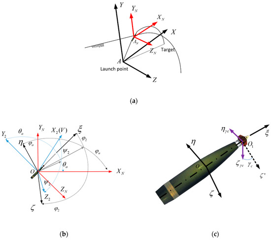
Figure 1.
Reference frame of the projectile. (a) Description of the launch-fixed reference coordinate system, with launch reference coordinates. (b) Description of the launch-fixed reference coordinate system, velocity coordinate system, and projectile axis coordinate system. (c) Description of the projectile axis coordinate system and fixed canard coordinate system.
In Figure 1b, points toward the velocity of the projectile, is orthogonal to and points upward, and is orthogonal to and , with the usual right-hand rule.
In Figure 1c, points to the head of the projectile and is parallel to the axis of projectile, is orthogonal to and points upward, and is orthogonal to and , with the usual right-hand rule.
The difference between and is , which is the roll angle of the fixed canards.
The transformations of the different coordinate systems are expressed as follows:
The relationship between the velocity coordinate system and the launch-fixed reference coordinate system can be expressed as:
The relationship between the projectile axis coordinate system and the launch-fixed reference coordinate system can be expressed by:
The relationship between the fixed canard coordinate system and the projectile axis coordinate system can be expressed as:
2.2. Model of Fixed Canards
The front view of the projectile is shown in Figure 2a. As shown in Figure 2b, there are two pairs of canards with fixed deflection angles. One pair of them produces the required rotational forces to halt the spinning of the projectile. Another pair of them provides the steering forces to control the attitude of the pitch and yaw angles of the projectile. The roll angle of the fixed canards is defined as 0° (from 0° to 360°) when the canards provide upward steering forces from the view of the top of the fixed canards, and the roll angle increases as canards rotate counterclockwise, as shown in Figure 2b.
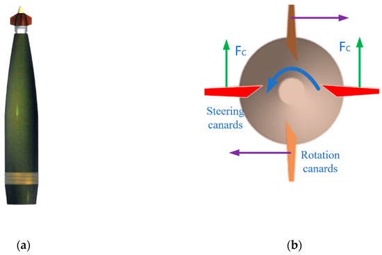
Figure 2.
Diagram of the projectile. (a) Front view of projectile. (b) Diagram of the canards (top view).
Without the steering control, the average steering forces are nil while the fixed canards rotate freely. When the relative spin rate between the fixed canards and the projectile is the same to the self-spin rate of projectile, the fixed canards are stationary to the ground and can give sustained steering forces to correct the trajectory course.
The velocity of the projectile, , in the fixed canard coordinate system can be expressed as:
where
This is the transformation matrix between the velocity coordinate system and the projectile axis coordinate system.
The projection of on the canards does not produce steering forces. The projection of on the orthogonal direction of canards, which can be expressed by , enables the fixed canards to correct the course of the projectile. The steering force, , and the drag force, , in the fixed canard coordinate system can be expressed as:
The produced force, , in the velocity coordinate system can be expressed as:
The steering moment, , in the projectile axis coordinate system can be expressed as:
2.3. Control Model Based on Fixed Canards
A seven degrees of freedom (7-DOF) control model was established based on the uncontrolled rigid body trajectory model. The kinematic and dynamic equations in the velocity coordinate system and projectile axis coordinate system are given respectively as follows:
Kinematic equations:
Dynamic equations:
The resultant force in the velocity coordinate system and the resultant moment in the projectile axis coordinate system can be expressed as follows, respectively:
These equations of forces and moments can be inferred by [27].
3. Correction Characteristics of Fixed Canards on Trajectory
In this section, the angular motion of fixed canards is analyzed and the coupling of forces on the normal and lateral directions are analyzed and resolved. Then, the trajectory correction range is elucidated based on the analysis of the correction abilities of the canards.
3.1. Control Model Based on Fixed Canards
To further study the angular motion of the fixed canards as well as the correction ability, the control model established in Section 2 is simplified.
Referring to the methods in [27], it is defined that:
Additionally,
The pitch angles of the projectile axis and velocity, which are relative to the ideal trajectory, can be expressed as:
, as mentioned above, are considered small variables.
Here, we define the complex wing angle as and the complex deflection angle as .
Thus, the angle of attack, , in complex, can be presented by:
Additionally,
In the ideal trajectory, , the second and third equation in Equation (10) can be combined and simplified as:
where this is the equation of the complex deflection angle.
According to small-perturbation theory, , and the third and fourth equation in Equation (12) can be combined and simplified as:
where this is the equation of complex wing angle.
Combine Equations (21) and (22), then
When the independent variable is defined as , the length of arc, and according to ,
Thus, the equation of angle of attack can be expressed as:
where
According to the frozen coefficient method, are regarded as constants in every small part of the trajectory, such that Equation (27) can be resolved with the nonhomogeneous differential equation with a constant coefficient, and the general solution of the equation, , can be described as:
where is the general solution in Equation (27), is dynamic equilibrium angle caused by gravity, and is the dynamic equilibrium angle caused by the fixed canards.
can be expressed as:
where coefficient and depend on the initial condition and are the eigenvalues of the homogeneous equation.
For , can be expressed as:
When the angular motion caused by the fixed canards is the only variable considered, the equation can be expressed as:
In Equation (30), when is a constant, the special solution can be expressed as:
Additionally, according to Equation (31), this can be simplified as:
where .
3.2. Correction Characteristics of Fixed Canards on Trajectory
After figuring out the angular motion of the fixed canards, the correction characteristics of the fixed canards on the trajectory of the projectile were studied as follows, including the analysis of the decoupling of the correction directions, as well as the correction ability of the fixed canards.
3.2.1. Decoupling of the Correction Directions
The dynamic equilibrium angle, , produced by the fixed canards, is a complex angle of attack, where the argument of which can be represented using Equation (32):
According to Equation (33),
hardly changes in flight. This is because in a small part of the trajectory, can be regarded as constant. There is a constant difference between the argument of produced by the fixed canards and the roll angle of the fixed canards. The orientation of the angle of attack generated by the fixed canards is exactly the direction of the projectile that needs to be corrected to. Therefore, the control equation, Equation (34), of the projectile is obtained according to the relationship between the roll angle of the fixed canards and the correction direction, such that the projectile can be easily controlled by the fixed canards to correct its trajectory to the target.
Figure 3 shows changes, along with roll angle of the fixed canards, , when the angle of fire is 51°. The correction process is carried out at the vertex of the trajectory. in Figure 3 hardly changes when changes, indicating a corresponding linear relationship between and , such that their directions are opposite (the difference of the argument of them is approximately 180°).
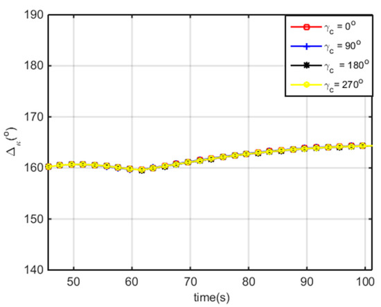
Figure 3.
Analysis of with different when angle of fire is 51°.
Similarly, this conclusion can be drawn from the analysis of the forces. Because and in the flight, the moment of momentum of the projectile is parallel to the axial direction. As shown in Figure 4, when , fixed canards produce an upward steering force, generating the pitch moment pointing to the right (defined in Figure 4). According to the theorem of the momentum moment, under the action of this moment, the projectile produces a downward swing angular velocity, , inducing the correct angle of attack. On the other hand, the right lift force, , induced by the right angle of attack, produces the downward moment , which could form a downward swing in the angular velocity, , thus producing a downward angle of attack. In conclusion, under the action of the upward steering force, the projectile would produce the angle of attack in downward and right directions. The final lift force, , is shown in Figure 4.
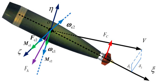
Figure 4.
Diagram of the forces of projectile.
As analyzed above, the direction of is not the same as the roll angle of the fixed canards but is instead almost opposite. Referring to Equation (34), the decoupling of the correction directions is achieved.
3.2.2. Features of Correction Ability
As shown in Figure 5, without the consideration of caused by gravity, is parallel to the axis of the projectile, and the deflection angle of the fixed canards is . In Figure 5a, for the coupling effects analyzed in last section, when the projectile corrects to the right, the fixed canards provide a steering force pointing to the left (). Then, for the influence of the steering force, the axis of the projectile swings to the right and . Similarly, in Figure 5b, when the projectile corrects to the left, the fixed canards provide a steering force pointing to the right (). Then, for the influence of the steering force, the axis of the projectile swings to the left and .
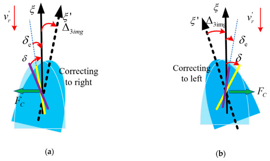
Figure 5.
Force analysis when correcting to different orientations. (a) Correcting to right. (b) Correcting to left.
From the analysis above on the change of , without the consideration of , it is difficult for spinning-stabilized projectiles to achieve correction to any direction with fixed canards, for they have a great coupling effect.
The intensive gyroscopic effect of spinning-stabilized projectiles would lead to a relatively bigger , the dynamic equilibrium angle caused by gravity, especially in the right direction. A simulation of is shown in Figure 6. It indicates that is much greater than , and that their time evolution maps are almost the same for different angles of fire. The greater the angle of fire is, the greater they are, and they reach a maximal value at the vertex of the trajectory.
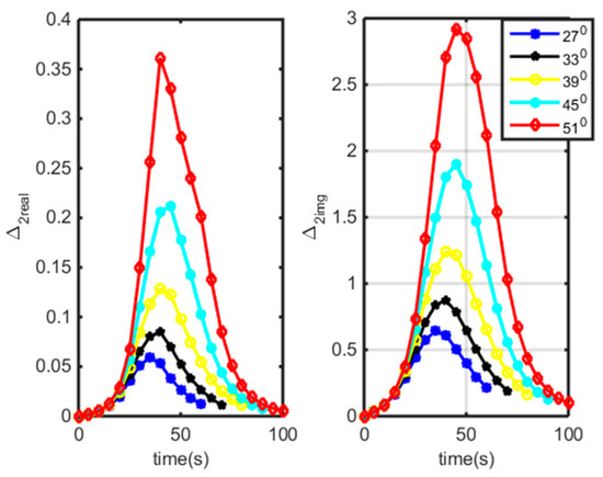
Figure 6.
Time evolution of and at angles of fire of 27°, 33°, 39°, 45°, and 51°.
As shown in Figure 7a, with the consideration of caused by gravity, , the fixed canards produce a force pointing to the left, while the projectile swings to the right and . Similarly, in Figure 7b, when the fixed canards produce a force pointing to right, . With the steering force, the projectile swings to the left, and .
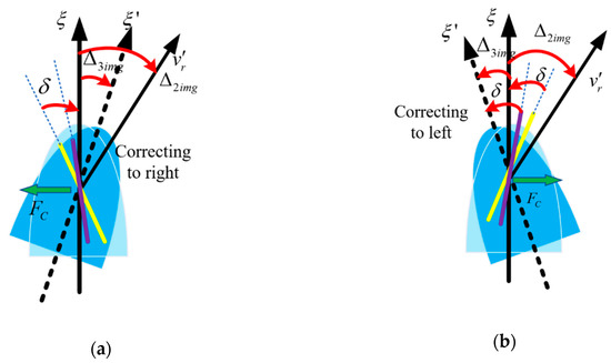
Figure 7.
Force analysis when correcting to different directions with the consideration of . (a) Correcting right. (b) Correcting left.
From the analysis above, decreases when correcting to right and increases when correcting to left, which indicates that it is more difficult for a spinning projectile with fixed canards to correct to the right in the correction process, while correcting to the left is relatively easier.
3.2.3. Analysis of the Correction Range
The dispersion of impact points corrected by fixed canards is like an ellipse when the roll angle of the canards varies from 0° to 360°. The correction ability with different roll angles of the fixed canards will be discussed as follows.
As for the 155 mm gun-launched guided projectile with fixed canards, the simulation of the distribution of impact points at different roll angles of fixed canards is carried out henceforth. The parameters of the simulation are listed in Table 1.

Table 1.
Parameters of the simulation.
In the simulation, the correction process begins after the projectile reaches the vertex of the trajectory. In Figure 8, the ellipses in red, blue, black, and green present different groups of simulations, where the correction start times of which are 45, 55, 65, 75, and 85 seconds after the projectile reaches the vertex point, respectively. The roll angles of the fixed canards of each group vary from 0° to 360°, with a pace of 15°.
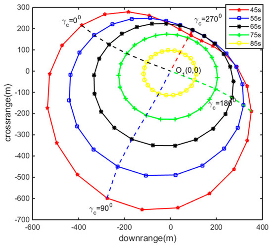
Figure 8.
The corrected impact points at different start times and roll angles for fixed canards.
Figure 8 indicates that with the increase of the start time of the trajectory correction, the distance of correction decreases and the correction distance on the left is larger than the right. The distribution of the corrected impact points can be regarded as an ellipse obtained by the ellipse fitting method, where the center of which does not overlap with the target point O1 (also called the aiming point under uncontrolled conditions). Here, the ellipse is the basis with which to analyze the aiming method.
When the canards are fixed with a certain deflection angle, and other factors, such as the muzzle velocity and spin rate are almost consistent, the correction results mainly depend on the angle of fire. The corrected impact points with different angles of fire are shown in Figure 9, where the start time of trajectory correction is the time when the projectile is at the vertex of the trajectory.
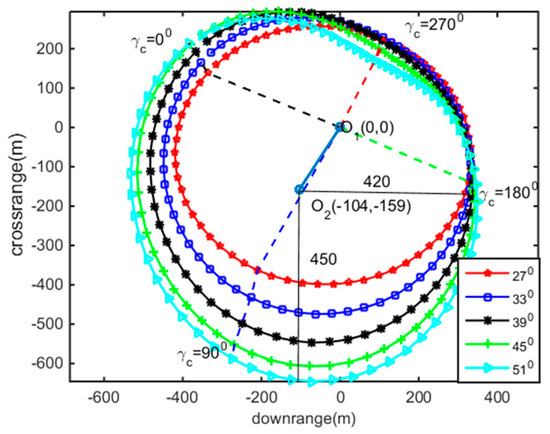
Figure 9.
The maximum correction ability under the different angles of fire.
In Figure 9, the distribution of the corrected impact points can be regarded as an ellipse obtained by the ellipse fitting method. Here, the center of correction of the ellipse is O2. The deviations between O2 and O1 in the range and lateral directions are −104 m and −159 m, respectively, which indicates correcting to the left is easier than correcting to the right for fixed canards. As for the dynamic equilibrium angle from gravity, , when > 0, correcting to nearer places is easier than correcting further. The length of the axis of the ellipse in the range direction is 420 m and length of the axis of the ellipse in lateral direction is 450 m, which indicates almost the same correction ability for fixed canards in both the range and lateral directions.
As analyzed above, the correction ability with different roll angles of fixed canards differs, and the correction ability of fixed canards cannot be taken full advantage of by aiming directly at the real target directly, for the fixed canards have a different correction ability in different directions. So, a novel aiming method is proposed based on the analysis of the characteristics of the ellipses generated by the corrected and uncontrolled impact point dispersions.
4. Virtual Target Aiming Method
The traditional aiming method is not the optimum choice for trajectory correction, and in order to make full use of the correction ability of fixed canards in all directions, a virtual target aiming method is proposed as follows. Based on the conclusion in Section 3, that correction ability varies with different roll angles of fixed canards, the determination of the virtual target position is discussed.
4.1. Comparison of Traditional and Virtual Target Aiming Method
As shown in Figure 10, the conventional aiming method takes the real target position, denoted by the purple dot, as the aiming point. The dispersion area of the uncontrolled impact points is represented by the ellipse in yellow. The ellipse in blue is the area called the correction area, where the uncontrolled impact points can be corrected to the target, which means as long as the projectile is delivered to any part of this area, its in-air trajectory can eventually be corrected to reach the real target.
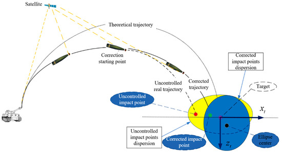
Figure 10.
The schematic diagram of the traditional aiming method and the impact point dispersion.
For instance, when the impact point of an uncontrolled projectile is located in the yellow area, but not covered by the blue area (correction area), the fixed canards are not able to correct the projectile to reach the real target position. Taking the impact points in Figure 10 as an example, when the location of the uncontrolled impact point denoted by the red dot is in the yellow area, the course correction projectile is unable to be corrected to the real target position denoted by the purple dot, where its actual impact point after trajectory correction is denoted by the green dot. The schematic diagram in Figure 10 shows us that the non-overlapped yellow area is part of the area that the trajectory correction projectile with fixed canards is not able to be corrected to the real target position.
Thus, in order to make the yellow and blue areas overlap as much as possible, a virtual target is proposed to make full use of the correction ability of the fixed canards. The virtual target aiming method takes the ellipse center of the blue area (correction area) as the actual aiming point, so that the impact points under uncontrolled conditions are mostly located in the blue area. Therefore, the new impact point area of the uncontrolled projectiles is of the same shape as the yellow area, but with the ellipse center at the virtual target point (the ellipse center of the blue area). In this way, the yellow and blue area overlap to the greatest extent, where most of the impacts point can be corrected to the real target point when they are controlled by the fixed canards.
4.2. Determination of the Virtual Target
The dispersion of the uncontrolled projectile fits a normal distribution, and are the variances in the range and lateral directions, respectively. As shown in Figure 11, according to the rule of thumb, the uncontrolled impact points are mostly located within the distribution curve , taking the real target position O1 as the origin, where the equation of which can be expressed by:
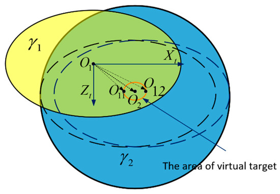
Figure 11.
Aiming point schematic diagram.
The biggest distribution ellipse of the corrected impact point is , where its ellipse center is O2, and its equation can be expressed by:
where is the coordinate of its ellipse center O2, is the length of the elliptical axis, and a,b > 0.
The projectile can eventually be corrected to the target, so as long as the predicted uncontrolled impact point of this projectile is located in . If the virtual target is set at a place where the uncontrolled impact point area and the area of correction ellipse mostly overlaps, then the uncontrolled impact points can be corrected to the target as much as possible. Here, we define the coordinate of the virtual target as . Because of the uncertainty of the correction ellipse and the uncontrolled impact point area, two different aspects are discussed.
• Aspect 1:
When , there are three possibilities: First, the area of the uncontrolled impact points is covered by the correction ellipse . Second, is not covered by . Third, is partly covered by . Although the location of and are not the same in these three cases, the relative size of and is definite. Therefore, the result of the three cases is the same. Taking the third case as an example, the virtual target can be set in any location of the ellipse with the red outline, as shown in Figure 11. The red outline of the ellipse is produced by the centers of the yellow ellipses when the yellow and blue ellipses are cut.
• Aspect 2:
When , or , the area of the uncontrolled impact points cannot be fully covered by the correction ellipse. To make the correction ellipse cover the uncontrolled impact points area as much as possible, the virtual target is set to the center O2 of the correction ellipse , as shown in Figure 12.
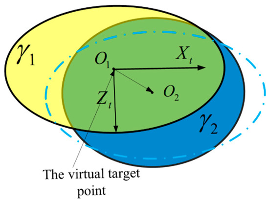
Figure 12.
Aiming point schematic diagram of Aspect 2.
Therefore, the range of the coordinates of the virtual target is given by:
In conclusion, the uncontrolled impact point area and the correction area can be obtained by experience, and the fitting of the correction range, respectively, and the area of the virtual target can be determined according to Equation (38).
5. Validation of Hardware-In-Loop Simulation
Hardware-in-the-loop simulation was conducted to verify the proposed aiming method, where Monte Carlo simulations were also carried out.
5.1. Description of Simulation
The block diagram of hardware-in-the-loop simulation is shown in Figure 13.
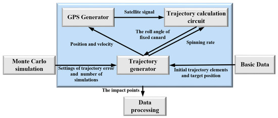
Figure 13.
Block diagram of the hardware-in-the-loop simulation.
As shown in Figure 13, The simulation environment consists of six parts: The trajectory generator, GPS generator, trajectory calculation circuit, basic data module, Monte Carlo simulation module, and data processing module. The trajectory generator simulates the real trajectory of projectile in real time. The GPS generator obtains the trajectory data from the trajectory generator, and updates the satellite signals with a frequency of 100 Hz to the trajectory calculation circuit. The trajectory calculation circuit sends the control signal of the fixed canards to the trajectory generator, where the trajectory generator generates the corrected trajectory after that. The PC is used to input the parameters of the trajectory to the trajectory generator, as well as deal with the processing of the data. The environment of the hardware-in-the-loop simulation experiment is shown in Figure 14.
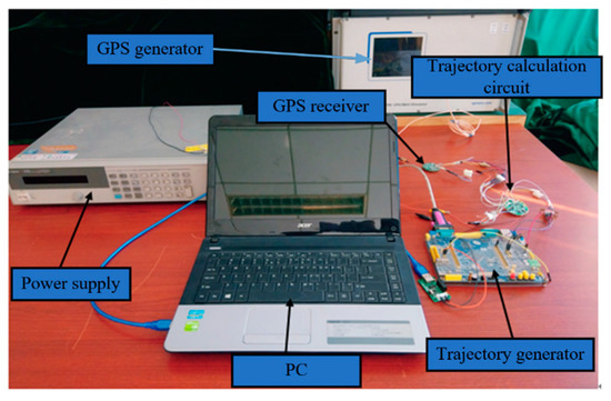
Figure 14.
Hardware-in-the-loop simulation environment.
The experimental procedure is given as follows. First of all, after the trajectory generator receives the respective parameters, including the initial trajectory elements, target position, and Monte Carlo simulation data, the simulation starts with the control of the PC. Then, the trajectory generator sends real-time information, including the position and velocity of the projectile, to the GPS generator, and sends the spin rate to the trajectory calculation circuit within a period of 0.1 s. The GPS receiver processes the satellite signals from GPS generator and sends the navigation data to the trajectory calculation circuit. The trajectory calculation circuit calculates the roll angle of the fixed canards with the inputs of the navigation data and spin rate, sends this angle to the trajectory generator. The trajectory generator uses the roll angle of the fixed canards to generate the corrected real-time trajectory. When the process above ends at a trajectory height of 0 m, the trajectory generator sends the data of the impact point to the PC, and the next simulation starts immediately. When all of the simulations were finished, the data were processed by the PC.
5.2. Set of Initial Parameters and Determination of Virtual Target
Taking the 155 mm gun-launched projectile as an example, the ideal uncontrolled impact point is (29886, 0, 1390.8) (m) in the launch reference coordinate system in a standard condition when the angle of fire is 51°. There are 9 kinds of error resources in the trajectory correction procedure, which are shown in Table 2.

Table 2.
Errors settings.
The Monte Carlo simulations were carried out 500 times, and the variances in the range and lateral directions, , in Equation (27) are given as m, m.
The parameters in Table 2 were applied in the Monte Carlo simulation and the angle of fire was set as 51°. Correction was conducted when the projectile was at the vertex of the trajectory.
Different deflection angles of the fixed canards were set to validate the claim that the proposed novel aiming method is able to improve the accuracy of spinning stabilized projectile with fixed canards. One of the deflection angles was 6°, the other was 3°. According to Equation (38), the parameters of these two kinds of correction ellipses and positions of virtual targets are given in Table 3.

Table 3.
The correction ellipses and virtual targets.
5.3. Results of the Simulations
The Monte Carlo simulations of the uncontrolled and corrected impact points were carried out to compare the striking accuracy of the traditional and virtual target aiming methods.
Figure 15a shows the impact points of uncontrolled and controlled projectiles around the target. The results in Figure 15a indicate that the correction area does not cover all of the uncontrolled impact points, though the correction ability of the fixed canards was greater than 3°. As show in Table 4, the CEP (circular error probable) of the virtual target aiming method was 31 m, while the CEP of the traditional aiming method was 46 m. As we can see, the virtual target aiming method improves the accuracy by 32%.
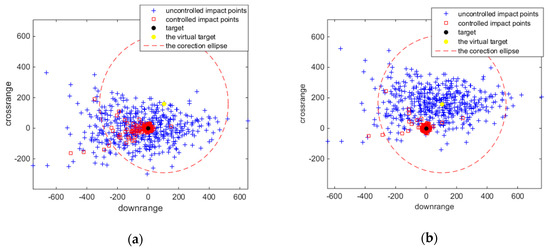
Figure 15.
Type 1 Monte Carlo simulation results. (a) Traditional aiming method. (b) Virtual target aiming method.

Table 4.
Simulation results of Type 1.
The simulation results of Type 2 are shown in Figure 16. Compared with the traditional aiming method, there were more uncontrolled impact points located within the correction range when using the virtual target aiming method, which indicates that there are more uncontrolled impact points that can be corrected to the real target with this method. As show in Table 5, the CEP of the virtual target aiming method was 69.3 m, while the CEP of traditional aiming method was 90.75 m. The virtual target method can improve the striking accuracy by more than 20%.
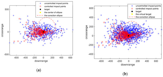
Figure 16.
Type 2 Monte Carlo simulation results. (a) Traditional aiming method. (b) Virtual target aiming method.

Table 5.
Simulation results of Type 2.
In conclusion, when the correction range is not large enough to cover all of the uncontrolled impact points, the application of virtual target point aiming method can improve the projectile’s CEP with limited fixed canard correction ability to a large degree.
6. Conclusions
Here, a novel aiming method for spin-stabilized projectiles with course correction fuze actuated by a fixed canard is proposed. The method has been verified based on the analysis of the decoupling and correction characteristics of spinning projectiles. Unlike the conventional aiming method, this study takes full advantage of the correction ability of fixed canards to improve the precision of trajectory correction. This method only needs to determine the virtual target by the analysis of the area of the uncontrolled impact points and the correction area.
From the analysis of the fixed canards’ mechanism, the fixed canard model was set up. Combining the uncontrolled rigid body trajectory model, the correction model of spinning projectiles was established. The angular motion of fixed canards was analyzed based on the linearized correction model by small disturbance theory and the frozen coefficient method. By analyzing the dynamic equilibrium angle produced by the fixed canards, the trajectory correction characteristics of fixed canards, including the correction direction and the correction features, were studied. There is a corresponding linear relationship between the direction of the dynamic equilibrium angle produced by the fixed canards and roll angle of fixed canards, and directions between them are opposite. When the projectile needs to be corrected to the left, fixed canards have the ability to provide a steering force pointing to the right and vice versa. Also, due to the existence of the dynamic equilibrium angle from gravity, it is more difficult for spinning projectiles with fixed canards to correct to the right when compared correcting to the left in the correction process. Based on the analysis of the area of uncontrolled impact points and the correction ellipse, the virtual target aiming method is proposed.
At last, hardware-in-the-loop simulation was carried out. Monte Carlo simulations, with different correction ability, have shown that the novel aiming method can improve the striking accuracy of the course-corrected projectile by more than 20% when compared with the traditional aiming method. Further research, such as the theoretical derivation of the correction ellipse and simulation in actual weather conditions, will be conducted.
Author Contributions
Conceptualization, Q.S.; Data curation, J.C.; Formal analysis, J.C.; Funding acquisition Q.S.; Investigation, Q.S. and J.C.; Methodology, Q.S. and J.C.; Project administration, Q.S.; Resources, Q.S.; Software, J.C.; Supervision, Q.S.; Validation, Z.D. (Zilong Deng); Visualization, Z.D. (Zhaowei Deng); Writing—original draft preparation, Z.D. (Zhaowei Deng) and Z.D. (Zilong Deng); Writing—review and editing, Q.S. and Z.D. (Zilong Deng).
Funding
This research received no external funding. The APC (Article Processing Charge) was funded by Qiang Shen.
Acknowledgments
We would like to thank the National Key Laboratory of Science and Technology for the electromechanical dynamic characteristics at the Beijing Institute of Technology for their support during the writing of this paper.
Conflicts of Interest
The authors declare no conflict of interest.
References
- Shi, Z.; Zhao, L. Adaptive Output Feedback Autopilot Design for Spinning Projectiles. In Proceedings of the 36th Chinese Control Conference 2017, Liaoning, China, 26–28 July 2017; pp. 26–28. [Google Scholar]
- Wang, Y.; Wang, X.; Yu, J. Influence of control strategy on stability of dual-spin projectiles with fixed-canards. Def. Technol. 2018, 14, 709–719. [Google Scholar] [CrossRef]
- Pettersson, T.; Buretta, R.; Cook, D. Aerodynamics and flight stability for a course corrected artillery round. In Proceedings of the 23rd International Symposium on Ballistics IBC, Tarragona, Spain, 16–20 April 2007; pp. 647–653. [Google Scholar]
- Bybee, T. Precision guidance kit. In Proceedings of the 45th Annual NDIA Gun and Missile Systems Conference, Dallas, TX, USA, 18 May 2010. [Google Scholar]
- Assaf, M.; Ziv, M. System and Method for Guiding A Cannon Shell in Flight. US Patent No.US20180245895A, 25 August 2010. [Google Scholar]
- Burchett, B.; Peterson, A.; Costello, M. Prediction of Swerving Motion of a Dual-Spin Projectile with Lateral Pulse Jets in Atmospheric Flight. Math. Comput. Model. 2002, 35, 821–834. [Google Scholar] [CrossRef]
- Hahn, P.; Frederick, R.; Slegers, N. Predictive Guidance of a Projectile for Hit-to-Kill Interception. IEEE Trans. Control Syst. Technol. 2009, 17, 745–755. [Google Scholar] [CrossRef]
- Creagh, M.A.; Meagh, D.J. Attitude Guidance for Spinning Vehicles with Independent Pitch and Yaw Control. J. Guid. Control Dyn. 2010, 33, 915–922. [Google Scholar] [CrossRef]
- Rogers, J.; Costello, M. Design of a Roll-Stabilized Mortar Projectile with Reciprocating Canards. J. Guid. Control Dyn. 2010, 33, 1026–1034. [Google Scholar] [CrossRef]
- Costello, M.F. Potential Field Artillery Projectile Improvement Using Movable Canards; Report ARL-TR-1344; US Army Research Laboratory: Aberdeen Proving Ground, MD, USA, 1997; p. 52. [Google Scholar]
- Frost, G.; Costello, M. Linear Theory of a Rotating Internal Part Projectile Configuration in Atmospheric Flight. J. Guid. Control Dyn. 2004, 27, 898–906. [Google Scholar] [CrossRef]
- Frost, G.; Costello, M. Control Authority of a Projectile Equipped with an Internal Unbalanced Part. J. Dyn. Syst. Meas. Control 2006, 128, 1005–1012. [Google Scholar] [CrossRef][Green Version]
- Li, J.; Gao, C.; Li, C. A survey on moving mass control technology. Aerosp. Sci. Technol. 2018, 82–83, 594–606. [Google Scholar] [CrossRef]
- Fresconi, F.; Celmins, I.; Silton, S.; Costello, M. High maneuverability projectile flight using low cost components. Aerosp. Sci. Technol. 2015, 41, 175–188. [Google Scholar] [CrossRef]
- Costello, M.; Allen, P. Linear theory of a dual-spin projectile in atmospheric flight. J. Guid. Control Dyn. 2000, 23, 789–797. [Google Scholar] [CrossRef]
- Raúl, C.; Cadarso, L.; Sánchez, J. Guidance and control for high dynamic rotating artillery rockets. Aerosp. Sci. Technol. 2017, 64, 204–212. [Google Scholar]
- Xu, N.; Yu, J.; Wang, Y.; Wang, L. Analysis of Dynamic Characteristics of Fixed-wing Dual-spin Projectiles. Acta Armamentarii 2015, 36, 602–609. [Google Scholar] [CrossRef]
- Ahmed, E.; Wang, Y. Accuracy Improvement Capability of Advanced Projectile Based on Course Correction Fuze Concept. Sci. World J. 2014, 2014, 273450. [Google Scholar] [CrossRef]
- Wang, Y.; Song, W. Correction Mechanism Analysis for a Class of Spin-stabilized Projectile with Fixed-canards. Eng. Lett. 2015, 23, 269–276. [Google Scholar]
- Philippe, W.; Friedrich, L.; Denis, B.; Joseph, J. Wind tunnel tests and open-loop trajectory simulations for a 155mm canards guided spin stabilized projectile. In Proceedings of the AIAA Atmospheric Flight Mechanics Conference and Exhibit, Honolulu, HI, USA, 18–21 August 2008. [Google Scholar] [CrossRef]
- Theodoulis, S.; Sève, F.; Wernert, P. Robust gain-scheduled autopilot design for spin-stabilized projectiles with a course-correction fuze. Aerosp. Sci. Technol. 2015, 42, 477–489. [Google Scholar] [CrossRef]
- Theodoulis, S.; Gassmann, V.; Wernert, P.; Dritsas, L.; Kitsios, I.; Tzes, A. Guidance and Control Design for a Class of Spin-Stabilized Fin-Controlled Projectiles. J. Guid. Control Dyn. 2013, 36, 517–531. [Google Scholar] [CrossRef]
- Florian, T.; Philippe, W. Pitch/Yaw Channels Control Design for a 155mm Projectile with Rotating Canards, using a H∞ Loop-Shaping Design Procedure. In Proceedings of the AIAA SciTech Forum, AIAA Guidance, Navigation, and Control Conference, National Harbor, MD, USA, 13–17 January 2014. [Google Scholar] [CrossRef]
- Mcfarlang, M.B.; Hoque, S.M. Robustness of Nonlinear Missile Autopilot Designed Using Dynamic Inversion. In Proceedings of the AIAA Guidance Navigation and Control Conference and Exhibit, Denver, CO, USA, 14–17 August 2000. [Google Scholar] [CrossRef]
- Zhao, L.; Shi, Z.; Zhu, Y. Acceleration autopilot for a guided spinning rocket via adaptive output feedback. Aerosp. Sci. Technol. 2018, 77, 573–584. [Google Scholar] [CrossRef]
- Wu, Y.; Zhong, Y. Study on Angular Motion Characteristics of Spin-stabilized 2D Trajectory Correction Projectile under the Effect of Fixed-canards. Acta Armamentarii 2017, 7, 18–27. [Google Scholar] [CrossRef]
- Hang, Z. Exterior Ballistics of Projectiles and Rockets; Beijing Institute of Technology Press: Beijing, China, 2008. [Google Scholar]
© 2019 by the authors. Licensee MDPI, Basel, Switzerland. This article is an open access article distributed under the terms and conditions of the Creative Commons Attribution (CC BY) license (http://creativecommons.org/licenses/by/4.0/).