1. Introduction
Traditional networks are distributed in nature where control, management, and data planes are tightly and vertically coupled in each forwarding device. In traditional computer networking, the forwarding of data packets is controlled by using a control plane (for example, routing protocols) or by installing Access Control List (ACL) policies on the interfaces of data plane (for example, routers and switches). The ACL policies are manually installed at forwarding devices by using low-level commands which are often device-specific. SDN is a centralized architecture that separates both control and management planes from the data plane of the forwarding devices (routers and switches) by shifting both control and management planes at a centralized logical entity, called controller. As ACL policies are specified at the controller, therefore, the controller computes the shortest path for a data packet based on both network topology and ACL policies. Moreover, the controller computes and installs flow rules in the flow table of switches along the shortest path. Network management is greatly simplified in SDN and efficiently implements ACL policies [
1,
2] due to this centralization. Based on the flow rules, subsequent data packets of the flow are forwarded to different hosts. There are two types of timeouts attached to a flow rule; soft timeout and hard timeout. The soft timeout is the amount of time after which a flow rule is erased from the switches, if not used for the defined amount of time period, while the hard timeout is the amount of time after which a flow rule is deleted from the flow table of switches [
3]. The default values of soft and hard timeouts differ in various controller platforms and can be set by the administrator as per the requirements and specifications of a certain application [
4]. In our research work, we used a POX SDN controller and assumed static timeout values in both soft and hard cases for each flow rule. The ACL policies in communication networks are often changed, either to restrict/allow communication between hosts or because of a change in the network topology. Moreover, these policies help in implementing access control which restrict/allow communication as per source/destination Internet Protocol (IP)/Media Access Control (MAC) addresses, port numbers, protocols, priority, etc. to the users/applications [
5]. The high-level languages, Pyretic [
6] and Frenetic [
7] help to implement ACL policies via parallel and sequential composition operators in an efficient manner. Multiple policies are allowed by these composition operators for the communication of a specific set of packets. Moreover, one policy is allowed to process packets after another policy. These languages also address the problem of policy implementation based on an abstraction of the topology and packet model. It becomes beneficial for programmers who can build large and refined network applications out of small and independent modules. In SDN, the ACL policies are implemented at controller and flow rules are computed and installed at switches on the basis of these policies. However, this change in policies results in packet violations due to the existing flow rules installed at the switches based on old policies as discussed in [
8].
Currently, SDN implementation is getting much popularity due to its ease of management and centralization, for example, Google and Facebook are already using SDN for Wide Area Network (WAN) interconnectivity. It also improves hyperscale data center connectivity [
9]. In such kinds of data center internetworking and campus area networking, ACL policies change rapidly to restrict/allow communication between hosts or due to change in the network topology. In addition, these policies can be changed as per the requirements of users and applications. In such kinds of networks, packet violations due to the already installed flow rules result in delivering important data to invalid hosts that may cause security issues along with the loss of precious data. Our proposed mechanism first detects policy change via graph matching and then deletes conflicting flow rules from the data plane in addition to the installation of new flow rules as per new policies to resolve the problem of packet violations. In this way, it helps to minimize packet violations. As packets do not pass to invalid interfaces, therefore, it increases network efficiency and throughput. The policy change detection can be implemented via matrices, however, matrix computations take longer execution time and increase the number of packets violating the policies, this is formally proved in
Section 4.6. Thus, the existing approach [
8] cannot be implemented in real networks where there are frequent changes in ACL policies [
10]. In this paper, we suggest to store ACL policies using multi-attributed graphs and detect the change in policies by using the graph matching algorithm. Moreover, we have used abstractions to represent ACL policies which help network operators to easily specify, debug and manage these policies. We also show that our proposed approach reduces the computation time through theoretical proof and simulation results as compared to the existing approach. The rest of this paper is organized as follows:
Section 2 explains the related work,
Section 3 includes the problem statement. In
Section 4, a proposed solution is discussed.
Section 5 describes the performance analysis on the basis of simulation results. Finally, in
Section 6, the conclusion and future work are presented.
2. Related Work
This section includes a detailed survey of existing approaches related to our research problem. These approaches, along with their limitations and relevance to our research problem, are described in detail.
A prototype Network Debugger (NDB) [
11] provides breakpoints and packet backtraces as two primitives to debug SDN for black holes, loops, and other network-wide invariants. Backtrace outlines a breakpoint that exhibits an order of events which leads towards the specific breakpoint as per specific flow. NDB is based on two major components that are proxy and collector. Proxy works at the data plane as follows: when the data plane (router/switch) takes an action for a data packet, the proxy creates a postcard message and sends the postcard message to the controller. The postcard message is the truncated copy of the packet’s header which contains matching flow rule, switch, and output port. After receiving the postcard message, the collector at the controller saves postcards and produces backtrace for the listed data packets. The collector keeps the postcards in a hash table data structure, from where these can be recovered effectively. Veriflow [
12] attempts to detect network-wide invariants (like loops and reachability issues) in real-time and notifies or blocks those invariants to occur. The flow rules generated by the controller are passed through Veriflow for checking the network-wide invariants. In case, if network-wide invariants exist, then either a notification is sent to the network operator and the flow rules are installed at the data plane, or flow rules are blocked. There are also similar other works to debug traditional as well as SDN environments as [
13,
14] and [
15] which can detect network anomalies, ensure consistency of data forwarding plane [
16,
17] and allow several applications to run parallel in a non-conflicting way [
18,
19]. Network-wide invariants like loops and black holes are detected in No bug In Controller Execution (NICE) [
20] via model checking and symbolic execution. It proactively tests the SDN applications under diverse kinds of events by automatically generating streams of packets. It checks network-wide invariant conditions like loops or black holes, etc. Therefore, the space of possible system behavior and network invariants are explored by NICE orderly. Another tool, named Header Space Analysis (HSA), [
21] is beneficial for system administrators, as they can statistically examine their networks for the invariants, for example, ACL violations, black holes, loops, traffic isolations, etc. Although these approaches have the ability to check network-wide invariants in different scenarios, yet, these cannot auto-detect the network-wide invariants due to policy change.
PyResonance [
22] implements state-based network policies by using Pyretic [
6]. Pyretic has several composition operators to build a complex network control program by combining several modular control programs. Moreover, it utilizes composition operators to express state-based policies to compose multiple tasks via finite state machine and corresponding network application which determines the forwarding behavior of the state. Another mechanism, named Policy Graph Abstraction (PGA) [
23], provides automatic and conflict-free policies, for example, ACLs, load balancing [
24], etc. Considering an example, there may be multiple policy implementors, like network admin, system engineer, network manager etc., in a big organization. In such a scenario, network policy change consumes a large amount of time, as it needs extra attention to implement network policy to avoid conflict of existing and new policies. The focus of PGA is to avoid conflicts at the controller that are caused by implementing various policies. The OpenFlow Rules Placement Problem (ORPP) [
25] describes how to define and place flow rules in SDN at an appropriate place while following all technical and non-technical requirements (like ACL policies). It proposes two rules placement frameworks; OFFICER and aOFFICER. OFFICER uses optimization techniques to place the flow rules for the requirements whose flow rules are known and stable in a specific time interval, for example, ACL policies. aOFFICER utilizes adaptive control mechanisms to place the flow rules for the requirements whose flow rules are unknown and vary over a specific time interval (like load balancing requirements). Both OFFICER and aOFFICER techniques help to place flow rules efficiently. However, these works lack the ability to detect policy change and have no capacity to delete previously installed affected flow rules. vCRIB: virtualized rule management in the cloud [
26] facilitates data center operators by offering an abstraction for specifying and managing various rules. It automatically partitions and places the flow rules on hypervisors and switches to achieve the best trade-off of performance and scalability. DevoFlow [
27] provides a mechanism to modify OpenFlow model by breaking the coupling between control and global visibility. It allows operators to target only those flows which are important with respect to the network management. In this way, it minimizes switch-internal communication between the control and data planes. Infinite CacheFlow [
28] resolves the problem of limited number flow rules at switches by proposing a hybrid switch design (hardware and software) that relies on flow rule caching to provide large flow rule tables at low cost. When more flow rules are stored at the data plane, the probability of packet violation becomes higher for the packets whose ACL policies change at the controller after the corresponding flow rules are installed at the data plane. SwitchReduce [
29] proposes an approach that reduces switch state and controller involvement in SDN. It assumes that the number of match flow rules at any switch should not be more than the set of unique processing actions. Moreover, flow counters for each unique flow may also be maintained at only one switch in the network. The proposed approach can reduce flow entries up to 49% on first-hop switches, and up to 99.9% on interior switches. In addition to that, flow counters are also reduced by 75% on average. A flow entry management scheme for reducing controller overhead [
30] proposes a cache algorithm strategy "Least Recently Used (LRU)" for flow rules stored at the data plane to minimize the communication overhead between controller and data plane. By using this strategy, a switch can keep the recently used flow entries in the table to avoid the cache-miss problem. This, in turn, increases the flow entry matching ratio. These approaches not only ignore the case of ACL policies change and flow rules deletion from the data plane but also the installation of flow rules as per changed policies.
The authors in [
31] propose a new flow rule multiplexing mechanism that jointly optimizes the flow rule allocation and traffic engineering (like Quality-of-Service parameters) in SDN. The proposed mechanism states that the same set of flow rules, which are installed at each switch, may be applied by using different paths to the whole flow of a session. The mechanism is tested by using ITALYNET topology and results show that the proposed scheme saves Ternary Content Addressable Memory (TCAM) resources and guarantees high QoS satisfaction. It guarantees performance within a specific range of bandwidth resources. DomainFlow [
32] proposes a solution of flow level control and granularity in ethernet switches via OpenFlow by splitting the network into different slices and exact matches are used to enable practical flow management via OpenFlow protocol for Ethernet switches. The proposed mechanism can only be implemented with commodity switches with a small number of flows, which is not practical with respect to current trends that require an extensive number of flows, especially in case of change of policies and deletion and installation of rules. Another mechanism, called source flow [
33], proposes a solution to handle a large number of flows without effecting flow granularity. This scheme helps to minimize the problem of expensive and power-consuming search engine devices from the core nodes, and in turn, it helps to expand networks in a scalable way. This scheme is time-consuming in a sense that hosts produce millions of flows simultaneously and these flows are controlled on a per-flow basis. In [
34] an innovative SDN-based network architecture is proposed which guarantees exclusive access of network resources to a certain flow with the help of token-based authorization for the intended users/apps. The proposed system automates the reservation process and creates a strong binding between the end users/apps who request the reservation and flows. This, in turn, resolves the reservation problem of dedicated bandwidth of certain resources in high-speed networks for the transfer of data in distributed science environments. The research work in [
35] addresses the problem of verifying networks that contain middleboxes, such as, caches and firewalls. This work explores the possibilities of verifying the reachability properties for networks based on the ACL policies. In order to do that, the complex networks are sliced into small networks as per the network-wide verifications for the correctness properties. The results show that the time required to verify a network invariant in a complex network is independent of its size due to slices. This work is quite good for verifying network invariants in an efficient way. However, all these approaches do not consider the case when access rights (ACL policies) are changed and flow rules that are already installed at data planes are deleted.
In [
36] a security problem of priority-based flow rules is highlighted and the solution of the identified problem is presented. The problem is that the low priorities malicious flow rules can manipulate the whole OpenFlow network by making the high priority flow rules to fail. The authors proposed a solution which is called switch-based rules verification (SRV) to solve the identified problem. It works by leveraging the SDN controller to obtain the overall network view of the whole topology and detects malicious flow rules. This solution helps to detect a large number of flow rules in an efficient way. In [
37], actor-based modeling framework is proposed to investigate the problem of network verification. In this architecture, actors are basic units of computation that hold their own memory and can communicate via asynchronous messages. The paper shows how network applications are modeled by using Actors and how existing model checking mechanisms verify various properties (loops, policy violations, flow table consistencies) in SDN, so that network behaviors can be predicted to increase network efficiency. In [
38], the SDN-based simulation environment is created in the mininet emulator by utilizing the floodlight controller platform. In this environment, the flow table is assumed to be of six tuples, as per the information retrieved from the controller. After that, the distributed DOS attack model is constructed by combining the Support Vector Machine (SVM) classification algorithms. The results show that the average accuracy rate of detecting Distributed DoS (DDoS) attack of the proposed approach is 95.24% with a limited number of flow rules which are extracted from the controller. Ample research, as discussed above, on the verification of correctness properties of communication networks exist. However, none of these touches our identified problem to avoid packet violations by detecting policy change and installation/deletion of rules as per the change of ACL policy. Similarly, other works like [
14,
15] are helpful in debugging networks and detecting network anomalies and [
39] is helpful to run several applications on the same network in parallel without interfering with each other while maintaining the performance of each application. The above-cited works lack in the detection of the change of network policy as well as packet violations analysis due to the already installed conflicting rules on the data plane.
In [
40], a flow-rule placement mechanism called FlowStat is proposed which provides per-flow statistics to the SDN controller in addition to improve the performance of the network. The results suggest that the proposed approach provides per-flow statistics and improves network performance as compared to existing approaches, like ReWiFlow [
41] and ExactMatch. In [
42], a novel flow rule placement algorithm called hybrid flow table architecture is proposed which exploits the benefits of both hardware and software flow table implementations. The decision of placement of flow rules in the flow tables (hardware (expensive) or software (cheap)) of switches is handled dynamically to increase software-based flow tables utilizations which are non-TCAM modules. This mechanism helps to save expensive TCAM memory of switches without degrading network performance in terms of packet delay and packet loss. In [
43], a packet classification mechanism is proposed on the basis of lossy compression to create packet classifiers whose representations are semantically equivalent. The aim of this research was to find a limited size classifier that can classify a high portion of traffic to implement at switches of optimal TCAM size. The proposed approach can be implemented in a wide range of classifiers within different modules. The results based on diverse performance metrics in campus-based traffic reflect that it provides a significant reduction in real classifier size. In [
44] the fundamental capacity region of TCAMs is discussed by presenting fundamental analytical tools based on independent sets and alternating paths. This helps to validate the optimality of previous coding schemes. In [
45] a novel compression mechanism is proposed based on random access for forwarding tables. The system evaluation of this mechanism in real-life scenarios from different vendors and country locations shows that it provides much better results as compared to the existing mechanisms with respect to compression of forwarding tables. In [
46] formal approach to specify and verify Service Function Chain policies is presented. The aim of this research is to identify the presence of anomalies in the network policies before deployment. These approaches help to utilize the TCAM resources of switches efficiently, however, these research works do not consider policy change mechanisms in addition to analyze packet violations. The authors in [
8] state that changing or modifying network policies at the controller can lead to policy violations by the data packets for the flows whose flow rules are already installed at the data plane. They solve this problem as follows. The copies of flow rules generated by the controller are also stored at the controller. When their proposed approach detects the change in network policies at the controller, it removes those flow rules installed at the SDN switches that conflict with the changed network polices. This approach takes a longer time to detect the change in policy and subsequently leads to more number of packets violating the network policy. The detail is presented in the following section.
3. Problem Statement
The ACL policies change with the passage of time due to changes in the application environment or network topology. It is always difficult for network administrators to detect and implement this network policy change in the network. It is normally implemented manually which takes time to translate and implement these policies in an efficient and effective manner to avoid policy conflicts. In SDN, these policies are configured at controller which computes flow rules and installs them at the data plane along the shortest path between source and destination. Whenever there is a change in policies, it is not reflected immediately for already installed flow rules at the data plane. This results in packet violations due to the already installed flow rules at the data plane. In this regard, there is a need to have a fast detection of policy change approach at controller which can detect policy change and delete the conflicting flow rules in addition to installing new flow rules as per new policies. The policy change detection approach should be efficient with respect to cost, time, space and complexity. In addition, it can be implemented in a real-time networking environment where frequent policy change occurs. Moreover, the network policies should be defined in abstract form, so that, it becomes easy for network administrators to configure, debug and manage these policies.
We assume that the policies are 6 tuple <Source, Destination, Protocol, Ports, Service Function Chain, Action>. Here, Source includes Faculty (FCL) and Staff (STF) which consists of multiple IP subnets. The Destination comprises of the Learning Management System (LMS) and Web Server (WBS) and these consist of IP subset of servers on which multiple applications are implemented to achieve desired functionalities. The Protocol includes Transmission Control Protocol (TCP) or User Datagram Protocol (UDP) or ANY. Here, ANY represents both TCP and UDP traffic. The Ports include destination port numbers of applications which are assumed to be a set of ports = {port, port, ..., port}, where ≥ 0 represents integer values or ANY. The service function chain (S) sequence field specifies that communication between source and destination should be via Firewall (FW) or Load Balancing (LB) or ANY. Here, ANY represents both FW and LB from where traffic should pass. In addition, the field consists of Permit or Deny. This means that communication between Source and Destination is permitted or denied due to destination port numbers along with the specified protocol and S sequences. Finally, the detection and implementation of network policy change need to be implemented in such a way so that it reduces packet violations and increases network efficiency.
4. Proposed Solution
In this research work, the ACL policies are represented in 6 tuple <Source, Destination, Protocol, Ports, Service Function Chain, Action>. These policies are traversed into the policy implementation file, which is then passed to the controller. The controller computes a multi-attributed graph, G = (V, E, , ). Here:
V is a finite set of vertices that consists of three types, that is, Source, Destination and S sequence.
An edge in G is represented by E, which consists of a communication link (v, v) between two vertices (v and v∈ V).
consists of two types of attributes of vertices, namely, the EndPoint group (E
) and S sequence. Here,
= E
∪ S, where E
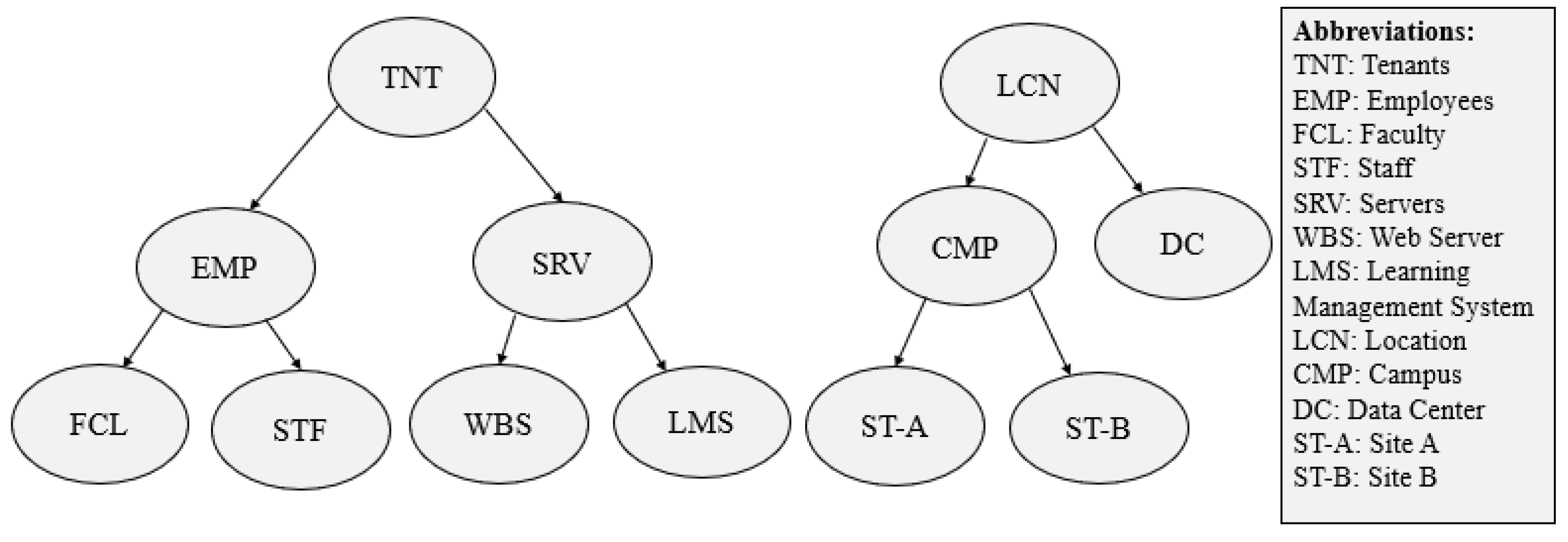
denotes an Endpoint Group (EPG) and S denotes service function chain sequence. An EPG comprises of collection of EndPoints (EPs). An EP is a minimum abstraction unit for which a policy is implemented, for example, server, subnet, network, or end-user. An EPG consists of all EPs which satisfies all conditions of membership predicate. Each membership predicate is assigned a label, for example, FCL, STF, LMS, WBS as shown in
Figure 1. The membership predicate is the boolean expression over all labels. In addition, there is S sequences for the network function boxes, for example, FW and LB to handle network communication. The composed graph shows which communication is allowed between network endpoints and what S sequence is required for the communication.
consists of two attributes of an edge, namely, and . The represents an attribute of an edge that comprises of values of TCP or UDP or its value can be ANY (which consists of both TCP and UDP traffic). The represents another type of edge attribute that comprises a set of destination port numbers of applications, that is, represents a set of integer values or ANY for a policy.
The system model of this research work is whitelisting, it means that by default no communication is allowed between the EPs. Moreover, in this work, reactive mode of flow installation mechanism is assumed in which controller computes flow rules in an on-demand fashion. More specifically, when a flow is generated, the controller computes the flow rules for that flow by using the network topology and ACL policies. It then installs flow rules at switches along the shortest computed path and caches a copy of flow rules in a Hash Table data structure. Suppose, later on, policy change is triggered, then controller computes the multi-attributed graph and policy change is detected via our proposed graph matching algorithm (that is, Algorithm 1). If there is no change, then no action is required, it means that the network is running as per the latest policies. Otherwise, the proposed approach finds out whether changed policies are conflicting with the flow rules cached at the controller or not. If matching is found then these are called conflicting flow rules. Contrarily, the flow rules are called non-conflicting. In this case, we can say that a new policy is added for the Source and Destination other than the existing ones. Thus, if there is no conflict, it means that a new policy is added for hosts other than the existing ones or else the proposed approach deletes all those flow rules from the flow tables of switches along the shortest path and from the controller cache that are conflicting with the changed policies. Finally, new flow rules and shortest paths are computed as per new policy and these newly computed flow rules are installed along the shortest path at switches and cached at the controller for further processing.
The proposed solution is discussed in four steps. In the first step, we list down the network policies as per our network scenario in a policy file, say at time t and pass the policy file to the controller. We represent these policies via a multi-attributed graph (say G), where, G = (V, E, , ). Here, V is finite set of vertices at time t which consists of Source, Destination and S sequence. An Edge in G is represented by E that consists of a communication link (v, v) between two vertices (v and v∈ V). consists of two types of attributes, namely, EndPoint group () and sequence. consists of two attributes of an edge, namely, and . The represents the attribute of an edge that comprises of values of TCP or UDP or ANY, where ANY represents both TCP and UDP traffic. Moreover, the represents another type of attribute of the edge that comprises a set of destination port numbers of applications. Here, consists of a set of integer values or ANY for a policy. In the second step, it installs flow rules in flow tables of the switches along the shortest computed path. In the third step, it caches a copy of flow rules in a hash table data structure at the controller. In fourth step, suppose, later say at time t, policy change triggers, then controller computes the multi-attributed graph (say G), where, G = (, E, , ). Here, V is finite set of vertices at time t which consists of Source, Destination and S sequence. An Edge in G is represented by E which consists of a communication link (v, v) between two vertices ( and ∈ V). consists of two types of vertex attributes, namely, EndPoint Group () and S sequence. consists of two attributes of an edge, namely, and . The represents the attribute of an edge that comprises of values of TCP or UDP or ANY, where ANY represents both TCP and UDP traffic. Moreover, the represents another type of an edge attribute that consists of a set of destination port numbers of applications. Here, consists of a set of integer values or ANY for a policy. In the fifth step, new flow rules and shortest paths are computed between Source and Destination as per new policies. Moreover, the newly computed flow rules are installed along the path in flow tables of switches and cached at the controller for further processing.
4.1. Policy Representation
In our proposed solution, we represent network policies in 6 tuple < Source, Destination, Protocol, Ports, Service Function Chain, Action > and construct the multi-attribute graph with the help of PGA for the composition of these policies. In traditional networking environment, the network policy implementation process is largely manual and network administrator translates high level policies into low level commands to implement these policies on network devices. Policy change takes large amount of time and suffers inefficiencies, like, policy overlapping, policy conflicts etc. due to the distributed and manual policy implementation process. These issues become worse in automated network environments, for example, SDN applications in Enterprise networking environments, Network Function Virtualization (NFV), cloud infrastructures etc.
Let us take an example of three ACL policies to understand the above mentioned policy composition issues. Suppose that we have three network policies to be defined at controller as follows:
Policy-1 (P):
Faculty has access to LMS server via TCP Port 20 through FW and LB Service Function Chain
Policy-2 (P):
Employees (Faculty and Staff) have access to the servers via TCP Ports 20, 25, 80 through FW
Service Function Chain
Policy-3 (P):
Faculty can communicate with Staff via TCP Ports 20, 25, 80, 587, 993 through FW
Service Function Chain
The above three ACL policies (P, P, P) are represented in 6 tuple as:
P = <Faculty, LMS, TCP, 20, (FW, LB), Permit>
P = <Employees, Servers, TCP, (20, 25, 80), FW, Permit>
P = <Faculty, Staff, TCP, (20, 25, 80, 587, 993), FW, Permit>
There is conflict between policies P and P, because, through P, only Faculty can access the LMS server while staff cannot access it. However, through P, Staff can access all servers including LMS. So, there is policy conflict between P and P, as access is denied through P and is permitted through P. Similarly, both policies P and P also overlap, because by using P, Faculty access is permitted to LMS via TCP port 20 and in P, Employees (including Faculty) access is permitted to LMS including all Servers via TCP ports 20, 25, 80. The third policy P is conflict-free and non-overlapping, as it has no conflict and overlapping with the other two policies. We need a human operator who manually composes these policies into a composite policy to implement these policies correctly via if-then-else. This is shown in an SDN program as follows:
If_match(SRC = Faculty, DEST = LMS, TCP, DEST_PORT=20)
FWLB Service Function Chain
Else If_match(DEST = LMS)
Deny
Else If_match (SRC = Employees, DEST = Servers, TCP, DEST_PORT=20,25,80)
FW Service Function Chain
Else If_match (SRC = Faculty, DEST = Staff, TCP, DEST_PORT=20,25,80,587,993)
FW Service Function Chain
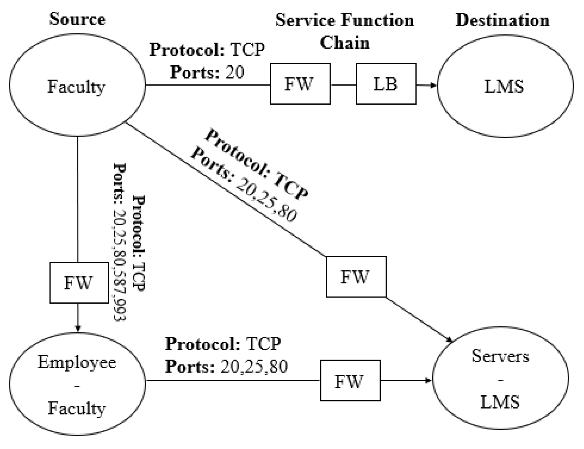
The above three policies are expressed correctly via graph composition as shown in
Figure 2. It shows that faculty can access LMS via two function boxes forming correct service chains required by both policies. As there is no relationship between staff and LMS, therefore, it aptly implements exclusive access to LMS which is required by P
. The other servers excluding LMS are denoted by set operator diff (‘-’), which allows communication with all employees along with faculty.
It implies that graph abstraction is very useful to express policies naturally and we can leverage graph structure to do automatic composition. PGA [
23,
47] has implemented this concept which enables users to easily specify and naturally draw some diagrams to capture network policies. In addition, it expresses policies via graph-based abstractions. Different stakeholders (users/tenants/admins) in addition to SDN applications produce network policies as graphs. These graph-based policies are further sent to the graph composer through a PGA User Interface (UI) which gets additional information from external sources for efficient policy formulation. After that, the graph composer provides a conflict-free graph after fixing all errors/conflicts. The conflict-free graph is composed of two steps. In the first step, input policy graphs are normalized by transforming their EPGs into an equivalent set of disjoint EPGs for the identification of policy overlappings. In the second step, the union of the normalized graphs is computed to obtain the final policy that can be implemented to the EPs. In the normalized form of graphs, EPGs in two different graphs are either disjoint or equal but do not partially overlap. This property helps multiple normalized graphs to be composed together using a simple union operation. Thus, the composed graph consists of the union of all the EPGs of individual graphs.
4.2. Flow Rule Caching
As we are using reactive mode for flow installation, therefore, the controller installs the flow rules at the data plane when a flow is generated in an on-demand fashion. The controller computes flow rules based on network topology, ACL policies, and other application requirements after receiving a request from the data plane to compute the flow rules for the flow. After this, as per our proposed approach, it caches one copy of the flow rules at the controller and installs the flow rules at the corresponding switches along the shortest path. We have used the hash table data structure [
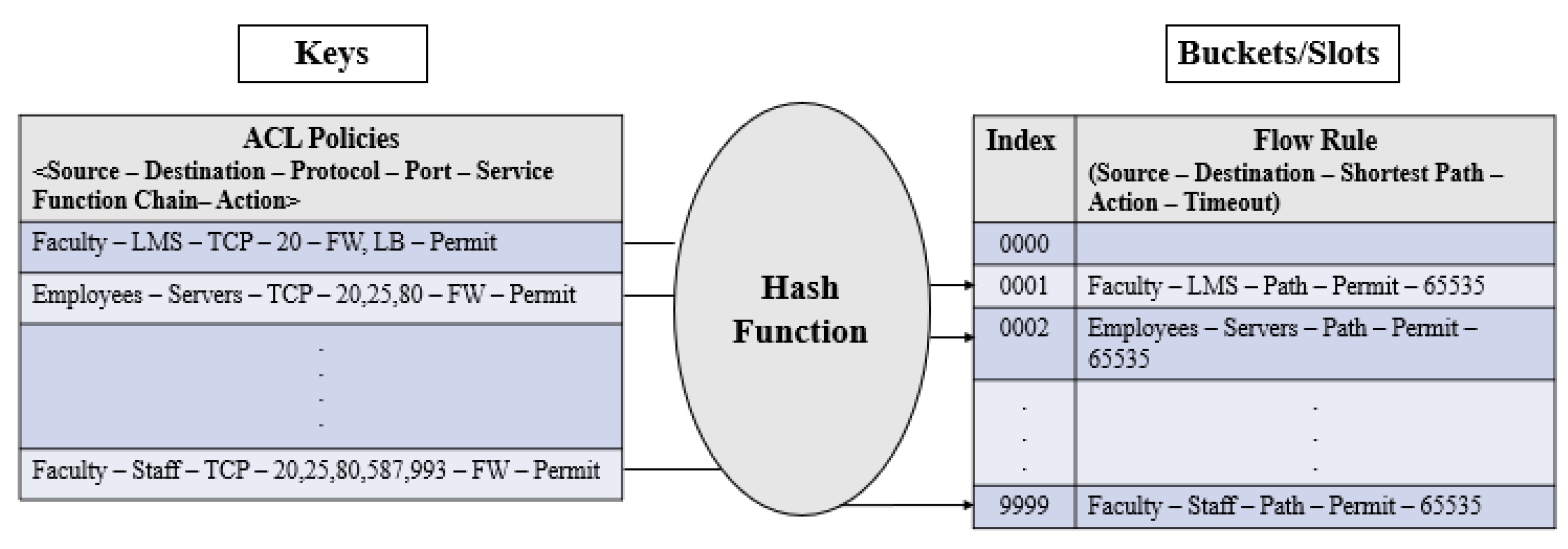
48] for caching flow rules at controller which maps keys to unique buckets/slots. It uses a hash function to compute an index into an array of buckets/slots which helps to retrieve the desired flow rule. In our proposed approach, we express keys and buckets/slots as tuples. The key tuple consists of ACL policies in 6 tuple <Source, Destination, Protocol, Ports, Service Function Chain, Action> while the bucket/slot tuple comprises of flow rules in 5 tuple, that is <Source, Destination, Shortest path between Source and Destination, Action, Timeout>. In our simulation, we have chosen the hash table length of 10,000 (0 to 9999) slots due to a limited number of nodes (hosts/switches). Moreover, we have used a consistent hash function [
49] as it produces the same output for a specific input, every time when the hash function is executed. It, in turn, helps to track specific flow rules against a defined network policy accurately. Whenever any change in policy is detected via Algorithm 1, then as per key tuple, the hash function is executed which points to a specific bucket/slot. Respective flow rule is deleted from the hash table of the controller on the basis of the hash function result. Moreover, as per the new policy, new flow rules are computed and installed along the shortest path in addition to caching these flow rules at the controller.
Figure 3 shows that the hash function is applied based on the key tuple, which points to a specific bucket/slot for caching flow rules at a specific index in the hash table.
4.3. Detecting Policy Change via Graph Matching
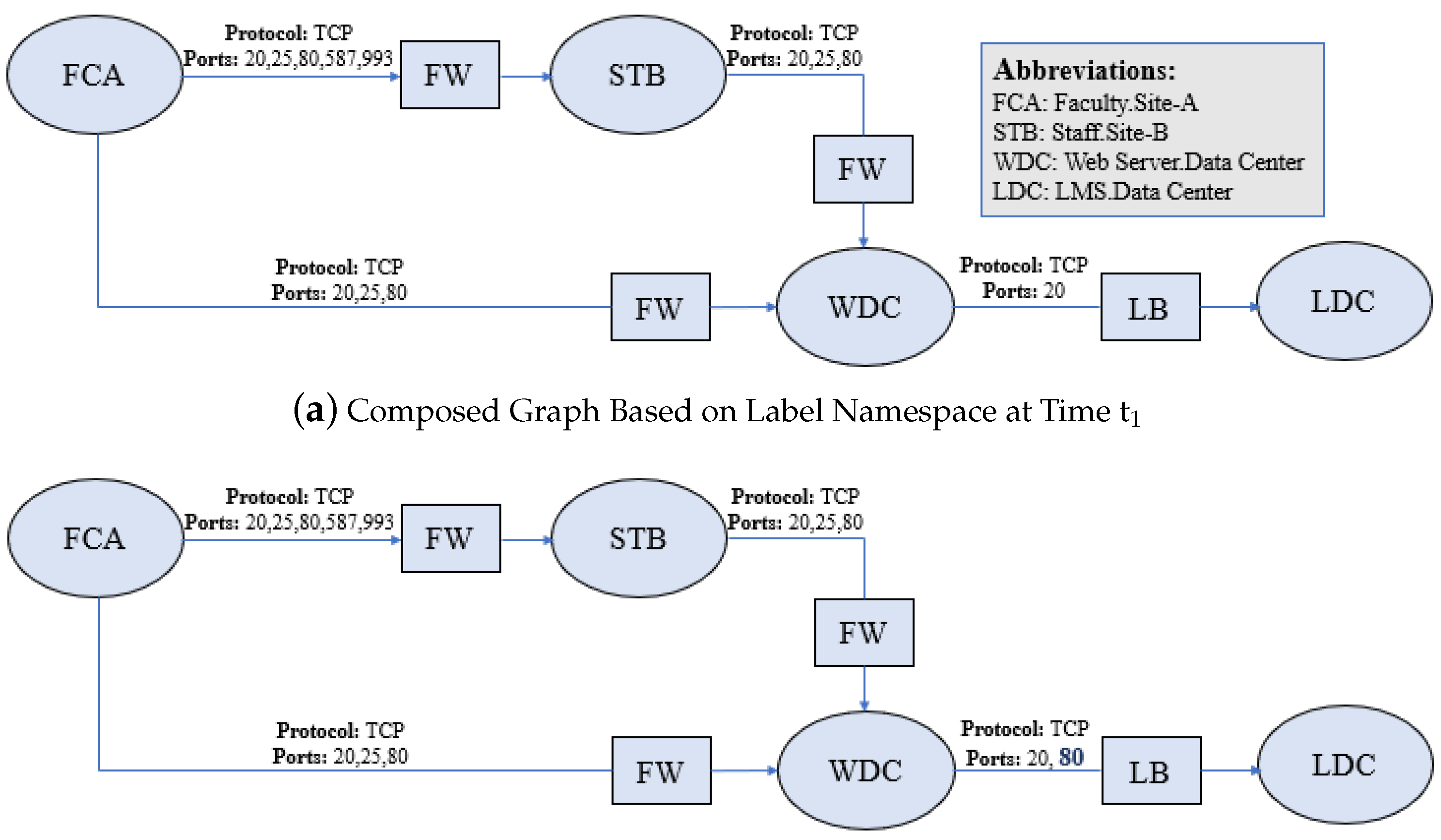
ACL policies change with the passage of time, as per requirements of different stakeholders, for example, network admins, system admins, application admins, etc. We computed the multi-attributed graphs for the policies at different instances of time (say t
and t
) with the help of PGA. The whole graph composition process is explained in
Section 4. The composed graphs at different time instances are compared based on Source, Destination, Protocol, Ports, Service Function Chain and Action. The Source, Destination and Service Function Chain are represented by vertices in the graphs and edges define relationship/connectivity between the vertices. The edges are attributed by protocol and a set of ports according to the implementations of network policies. The comparison is made for graphs by the exact graph matching algorithm to detect policy change. For the policy change detection, at first, the graph at time t
is computed which is shown in
Figure 4a. The graph is composed on the basis of three network policies (P
, P
, P
) which are described in
Section 4.1. Suppose, at time t
policy changes that state LMS is also accessible via port 80, then the composed graph is shown in
Figure 4b. After this, we compare these two graphs by using Graph Matching Algorithm, “Algorithm 1”, to detect that whether the policies are changed/modified or otherwise. By change, we mean whether the polices are modified or deleted or new policies are added. The matching is performed as follows.
Suppose, a directed multi-attributed graph G = (V, E, R
, R
). Here V is a finite set of vertices and E is a finite set of edges. These vertices and edges are associated with attributes that define their properties. In graph G, R
is a set of vertex attributes and R
is set of edge attributes. The vertex attributes in our network scenario are faculty, staff, LMS, and WBS. The edge attributes are protocol and ports as explained in
Section 4. Here:
V is a finite set of vertices
E ⊆ V x V is a set of directed edges
R⊆ V x A is a relation associating attributes to vertices, that is, R is the set of couples (v, A) such that vertex v is attributed by A
R⊆ V x V x A is a relation associating attributes to edges, that is, R is the set of triples (v, v, A) such that edge (v, v) is attributed by A.
The graph similarity is defined for two multi-attributed graphs G
= (V
, R
, R
) and G
= (V
, R
, R
) over the same sets of vertices A
and edge attributes A
, such that V
∩ V
= Ø and E
∩ E
= Ø. At first, vertices matching is checked to measure the graph similarity via matching each vertex with an empty set of vertices of the other graph. After that, a collection of common features of both graphs are identified to measure the similarities between both graphs [
50,
51]. The graph matching is applied on the features, like, Source, Destination, Protocol, Ports, Service Function Chain and Action in our network scenario. The following definitions are used in graph matching via graph isomorphism with the help of exact graph matching which is used in detection of change in network policies. In our scenario the graphs are generated based on ACL policies at time t
and at time t
. We intend to find instances of graph at time t
within graph at time
by allowing additional edges which is called graph monomorphism. Finding instances with no additional edges is called subgraph isomorphism and finding one-to-one mapping for all nodes and edges is called graph isomorphism. Our intention is to exploit concept of graph isomorphism for detection of policy change at different instances of time.
Definition 1. Suppose G = (V, E, α, β) which represents directed and multi-attributed graph for communication at time t where:
V is a finite set of vertices
E ⊆ V x V is set of edges and e(i,j) shows a directed edge which is communicating from vertex i to j.
α: v→A is a function which assigns unique attributes to each vertex in G such that α(i) ≠α(j)
β: E→A is a function which assigns unique attributes to each edge in G.
Definition 2. A subgraph of G with V⊆ V is represented by S(V) = (V, E ∩ V x V, α, β).
Definition 3. A function f: VV is a graph monomorphism from graphs G = (V, E, , ) to G = (V, E, , ), iff:
α(v) = α(f(v)), for all v ∈ V
β(e) = β(e), for all edges e = (v, v) ∈ E and e= (f(v), f(v)) ∈ E.
Definition 4. A function f: VV is a subgraph isomorphism from graphs G to G, if it satisfies Definition 3 and additionally it holds following conditions for every edge.
e = (v, v) ∈ E∩ f(V) x f(V) exists an edge
e = f(v) x f(v) ∈ E with v(e) = v(e).
Definition 5. A function f: VV is a graph isomorphism from graphs G to G, iff, f is bijective function and it satisfies Definition 4.
In our implementation, we adopt an exact subgraph isomorphism approach [
51] which is based on the divide-and-conquer principle. We have taken two graphs G
(input graph) and G
(model graph) that are generated on the basis of three policies, P
, P
and P
. These policies are explained in
Section 4.1. Moreover, the polices are implemented at times t
and t
respectively and represented with the help of graphs as shown in
Figure 4. The model graph is partitioned into disjoint subgraphs and subgraph isomorphism is checked for those disjoint subgraphs within the input graph. These graphs are merged to provide subgraph isomorphism of the full graph. Starting from full model graph G
, we divide set V into two disjoint sets such that V = V
∪ V
. The matching module is applied to both subsets S(V
) and S(V
). The outputs of partial matching modules are sent to the merge module for subgraph isomorphism, if possible. The V
and V
are further subdivided until we reach a single vertex. In this way, the hierarchy of partial matches is formed with respect to a binary tree.
The overall matching algorithm works on the basis of four categories of nodes as given in Algorithm 1. At the top, most of the hierarchy in nodes is the input-node, the second one is Attribute-Vertex-Monitor, the third one is Edge-Sgraph-Monitor and the fourth one is M-Model-Nodes. The input-node is the entry point of the matching algorithm. There are multiple edges from the Input-Node to the Attribute-Vertex-Monitor. At the time of execution, the input graph is forwarded to Attribute-Vertex-Monitor, that are quite simple matching mechanisms. Every Attribute-Vertex-Monitor characterizes a specific attribute of a vertex in the model graph which is attributed by an Attribute-Vertex-Monitor, if (v) = A. An Attribute-Vertex-Monitor takes vertices of input graph from the input-node. If the input vertex has attribute “A” then it is locally stored and forwarded to all descendant nodes. Every Attribute-Vertex-Monitor has single/multiple outgoing edges which leads to M-Model-Nodes or Edge-Sgraph-Monitors. The third type of nodes are Edge-Sgraph-Monitors which contain a minimum of two vertices and one edge. These nodes have two parents of either Attribute-Vertex-Monitor or Edge-Sgraph-Monitor. Each Edge-Sgraph-Monitor has two parent nodes which are either Attribute-Vertex-Monitor or Edge-Sgraph-Monitor types. The graph denoted by Edge-Sgraph-Monitor consists of two graphs of its parent nodes (n, n), which are represented by g (V, E, , ) and g (V, E, , ) graphs respectively. Moreover, graph denoted in Edge-Sgraph-Monitor n can be expressed as g (V, E, , ) with V = V∪ V; E = E∪ E∪ E. Here “E” denotes set of edges which are connected to n and any edge “e ∈ E” is the edge between g and g or between g and g. During the execution time, the Edge-Sgraph-Monitor “n” receives instances A of graphs (g and g). These instances are received from its parent node and merged in the graph “g” for instance “Arr”. The two instances are combined on the basis of two conditions. Firstly, these should be disjointed, and secondly, the edges should belong to both instances. Every new instance is saved in local memory and further forwarded to all successor nodes. Finally, last types of nodes are M-Model-Nodes, these are connected to a single parent node. Here, the graph representation is like model M. If any instance of the graph is detected in the parent node, it is forwarded to the M-Model-Node, where it is stored as an instance of model M. The exact graph matching is shown in Algorithm 1.
4.4. Checking the Flow Rules that Violate New Policies
In case of detection of policy change at time t
, the controller searches for those flow rules in its cache that are conflicting with modified policies. If there is no conflict, then no action is required because the network is running as per the changed ACL policies. Otherwise, the proposed approach deletes all those flow rules from both the flow tables at the switches and from the cache at the controller that is conflicting with the changed policies. More specifically, the controller keeps policies in hash table keys and forwarding rules along with the path in the respective bucket/slot. When bucket/slot is traversed to check flow rules installed by the conflicting policy, it returns all paths along with flow rules. If the source and destination of the path are matched with a flow rule in path’s switch flow table then respective flow rules are deleted both from the flow tables of the switches (as discussed in
Section 4.5) and from the cache of controller.
4.5. Deleting Flow Rules that Violate New Policies
As per the policy violation mechanism in
Section 4.4, the controller starts flow rules deletion from the flow tables of the switches as follows. We iterate over switches in the path and forward a flow deletion command via flow table modification message (OFPFC_DELETE) [
52] and append egress switch port number for flow rule deletion from the switch flow table.
4.6. Complexities of Existing and Proposed Approaches
We compare the complexities of both the Proposed and Existing approaches in order to show the improvement of our proposed approach theoretically. Suppose “n” represents the number of times a statement is executed. Then the execution frequency of existing approach [
8] is “n
+ 34n − 29” and the worst case complexity is O(n
). Similarly, the complexity of proposed approach is calculated which is “n
+ 6n + 27” and worst case complexity is O(n
) which shows improvement of complexity in our proposed approach.
| Algorithm 1 Detecting Policy Change via Graph Matching. |
- 1:
Procedure GraphMatch (G = (V, E, , )) - 2:
GE = E /*E are the edges of the Input-graph which are accessible globally*/ STEP-1 - 3:
for all Attribute-Vertices v in V do /*Input nodes of the graph*/ - 4:
for all Attribute-Vertex-Monitor do - 5:
Call Attribute-Vertex-Monitor (v) - 6:
end for - 7:
end for STEP-2 - 8:
Procedure Attribute-Vertex-Monitor (Vertex v) /*Checking vertices for matching*/ - 9:
if(v) = A then - 10:
A[0] = v - 11:
store A in the Local-Memory - 12:
for all Descendent Nodes n do - 13:
if n is an Edge-Sgraph then - 14:
Call Edge-Sgraph-Monitor - 15:
end if - 16:
if n is M-Model-Node then - 17:
Call M-Model-Node (A) - 18:
end if - 19:
end for - 20:
end if STEP-3 - 21:
Procedure Edge-Sgraph-Monitor (instance A) /* Checking Edge Subgraphs for matching*/ - 22:
if called by Left-Parent-Node then - 23:
for all instances A∈ local memory of Right-Parent do - 24:
if A and A are disjoint AND edge ‘e’ exists, such that e=(A[i], A[j] ∈GE AND v(e) = A AND there exists no additional edge, otherwise then - 25:
A = A + A /* The instance is concatenated*/ - 26:
Save Anew in Local-Memory - 27:
for all Descendant-Nodes n do - 28:
if n is Edge-Sgraph-Monitor then - 29:
Call Edge-Sgraph-Monitor (A) - 30:
end if - 31:
if n is M-Model-Node then - 32:
Call M-Model-Node (A) - 33:
end if - 34:
end for - 35:
end if - 36:
end for - 37:
end if - 38:
if called by Right-Parent-Node then - 39:
for all instances A∈ local memory of Left-Parent do - 40:
if A and A are disjoint AND edge ‘e’ exists, such that e=(A[i], A[j] ∈GE AND v(e) = A AND there exists no additional edge, otherwise then - 41:
A = A + A /*The instance is concatenated*/ - 42:
Save A in Local-Memory - 43:
for all Descendant-Nodes n do - 44:
if n is Edge-Sgraph-Monitor then - 45:
Call Edge-Sgraph-Monitor (A) - 46:
end if - 47:
if n is M-Model-Node then - 48:
Call M-Model-Node (A) - 49:
end if - 50:
end for - 51:
end if - 52:
end for - 53:
end if STEP-4 - 54:
Procedure M-Model-Node (instance A) /* Storing instance of Model Graph*/ - 55:
Save A in local-memory - 56:
Print the new instance A of the Model M
|

