Article

Parameter Extraction for Equivalent Circuit Model of RF Devices Based on a Hybrid Optimization Method

Key Lab of RF Circuits and Systems of Ministry of Education, School of Electronics and Information, Hangzhou Dianzi University, Hangzhou 310018, China
*
Authors to whom correspondence should be addressed.
Electronics 2019, 8(10), 1133; https://doi.org/10.3390/electronics8101133
Submission received: 6 September 2019 / Revised: 27 September 2019 / Accepted: 28 September 2019 / Published: 8 October 2019
(This article belongs to the Section Circuit and Signal Processing)

Abstract

:
One major difficulty of parameter extraction for an equivalent circuit lies in applying an optimization algorithm to efficiently approach the global minimum. Traditional genetic algorithm (GA) is able to find the global minimum but it has very low convergence rate. On the other hand, direct search method may be easily trapped in local minima. In this work, an improved parameter extraction method which is capable of effectively performing the global minimum search is proposed. This method combines GA and Powell’s method to efficiently determine circuit elements of an equivalent circuit model. A spiral inductor and an interdigital capacitor are used as design examples to illustrate the extraction procedure and validate the proposed hybrid method.

1. Introduction

Radio-frequency (RF) devices such as spiral inductors and microstrip interdigital capacitors have been widely used in low noise amplifiers, power amplifiers and voltage-controlled oscillators; and many other RF devices are used in silicon-based radio-frequency integrated circuits (RFICs) [1]. Accurate equivalent circuit models for these components are highly desirable for RFIC designs.
For a given device layout, an equivalent circuit can be constructed by a parasitic extraction tool. In general, the parasitic extraction tool is based on quasi-static analysis, which makes the equivalent circuit inaccurate at high frequencies. To improve the accuracy of the equivalent circuit model, it is a common practice to adjust the circuit elements of the equivalent circuit model by using accurate full-wave simulation results [2,3].
In practice, some RF devices can use simple T-, π- or ladder models as their equivalent circuits. For relatively complex RF designs, however, one may build better but more complex equivalent circuits based on their layouts with physical insights. For example, the equivalent circuits of the aperture-coupled resonator frequency-selective surface (FSS) [4], spiral inductors [5,6], and interdigital capacitors [7] have been constructed with physical insights. Once the equivalent circuit for a RF device is determined, the element parameters of the equivalent circuit can be extracted based on the full-wave results by optimization methods [8].
In order to build accurate equivalent circuit models, reliable and effective parameter extraction methods are required. In general, the values of circuit element parameters can be determined by genetic algorithm (GA) [9,10], which is an effective global and gradient-free optimization method. However, for the optimization problem of continuous function (e.g., the parameter extraction), the convergence rate of GA is slow, and particularly it is very ineffective for local optimization. More seriously, it is highly reliant on initial population [11]. If the initial population is not set appropriately, GA may be unable to find appropriate results. If a small population is used, the solution set will have small population diversity, and it may tend to cause the premature convergence problem [12]. As a result, the optimization solution may be inaccurate. Although some methods have been proposed to handle the premature convergence problem [13], the convergence rate of GA is hardly improved. In addition, if a large population is used, the optimization results may be more accurate, but the convergence rate becomes very slow. On the other hand, a conjugate gradient (CG) optimization algorithm, such as Powell’s method [14] combined with a one-dimensional search method (e.g., golden section search [15]), has strong local optimization ability and fast convergence rate [16], but the drawback of trapping in local minima restricts its applications.
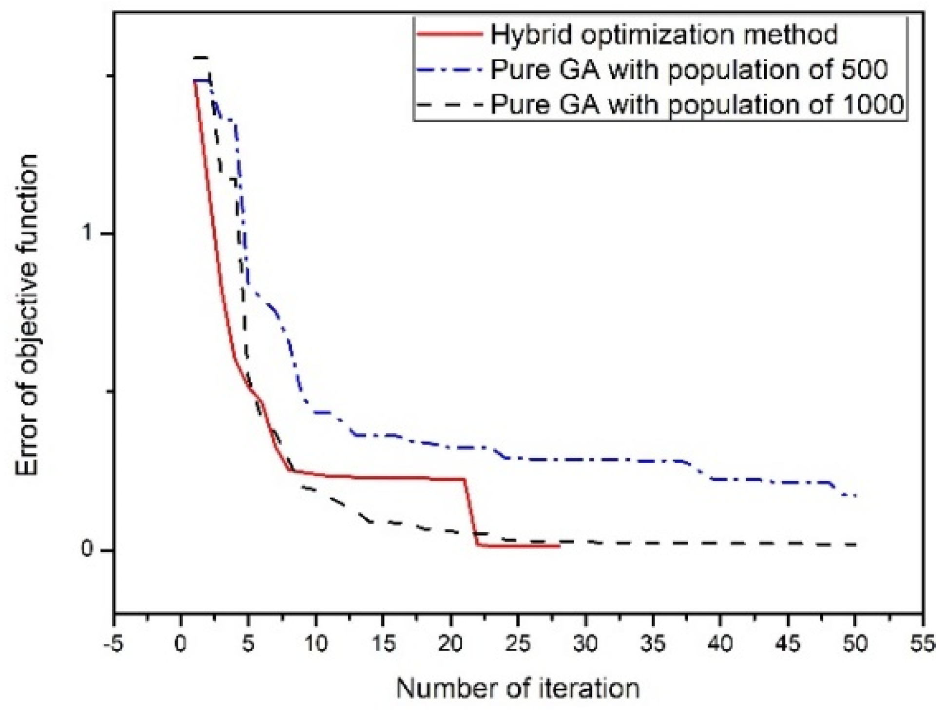
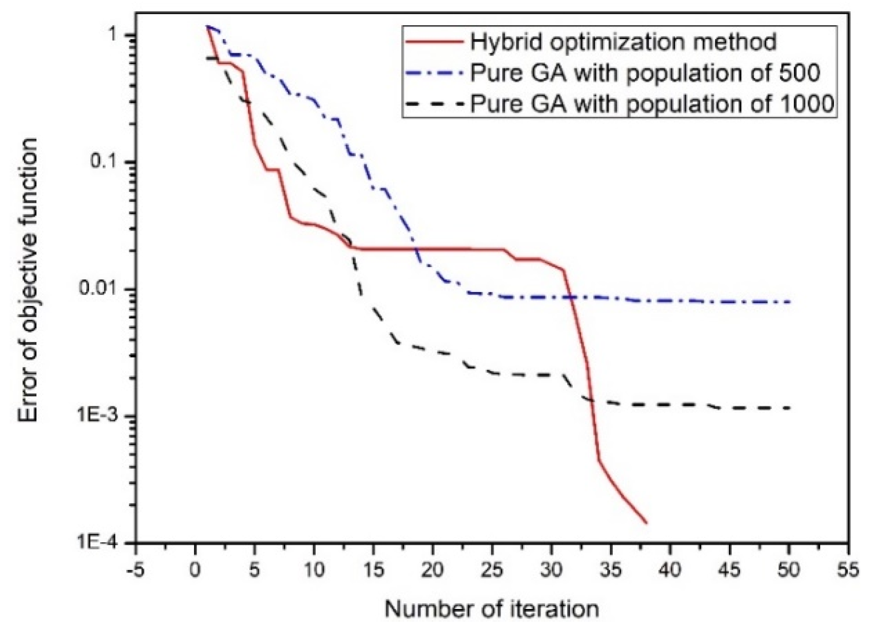
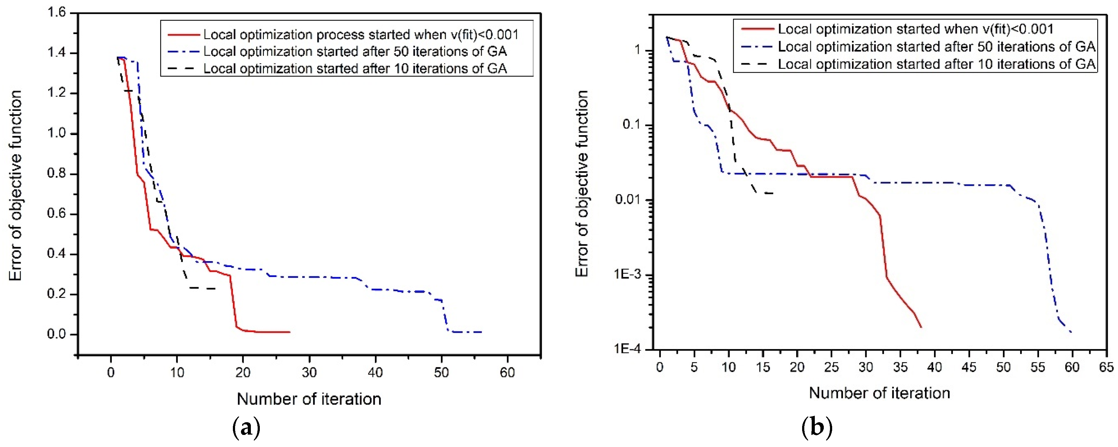
In this work, a parameter exaction method based on a hybrid GA–Powell’s method is proposed. The solution can be close to the global minimum after applying GA. Then, the best individual of GA is set as the start point of the local optimization process of Powell’s method. Determining when to start the local optimization process is important. If the local optimization process starts too early, the hybrid optimization method may easily trap at a local minimum. On the other hand, if it starts too late the hybrid optimization method may waste some unnecessary time on the global search process. To save the time on the global search process, the iteration number of the global search process is brutally reduced from 500 to 100 in a handbook [17]. However, it cannot be guaranteed that the result from 100 iterations of GA is an appropriate starting point of the local optimization process since the convergence rate differs from case to case. To effectively determine the appropriate starting point of the local optimization process, the variance of the fitness of population is used as a criterion. Using this hybrid optimization algorithm, an accurate solution of the global minimum is achievable. This method combines the merits of the global search ability of GA and the local search capability of Powell’s method with good accuracy and rapid convergence. Hence, this hybrid method is very effective in the parameter extraction of equivalent circuits.
To efficiently obtain the full-wave simulation results for a given device layout, a highly-efficient full-wave EM simulation tool, called UltraEM® [18], is employed to generate the Y-parameters of the device layout. These full-wave Y-parameters are set as the optimization objectives for the proposed hybrid GA–Powell’s method to adjust values of the circuit elements so that the difference between the full-wave Y-parameters and the Y-parameters of the equivalent circuit (which can be calculated by a circuit simulation tool [19]) is globally minimized.
The proposed method may have some limitations: Firstly, although this hybrid optimization method accelerates the parameter extraction of RF devices, it still cannot solve the problem of parameter extraction in a very wide frequency band, since RF devices may have different properties in different frequency bands [20]. That is, one specific equivalent circuit model may not be able to match the physical model of a certain RF device in its entire frequency band. Secondly, the efficiency of the hybrid optimization method is affected by its initial population of GA. If the initial population is inappropriately set, the proposed method may not be able to find the appropriate global minimum.
The rest of this paper is organized as follows. In Section 2, the hybrid optimization method based on GA and Powell’s method is introduced. The efficiency of this hybrid method is then tested and verified by modeling a planar spiral inductor and a microstrip interdigital capacitor in Section 3. A brief conclusion is given in Section 4.

2. Hybrid Optimization Method

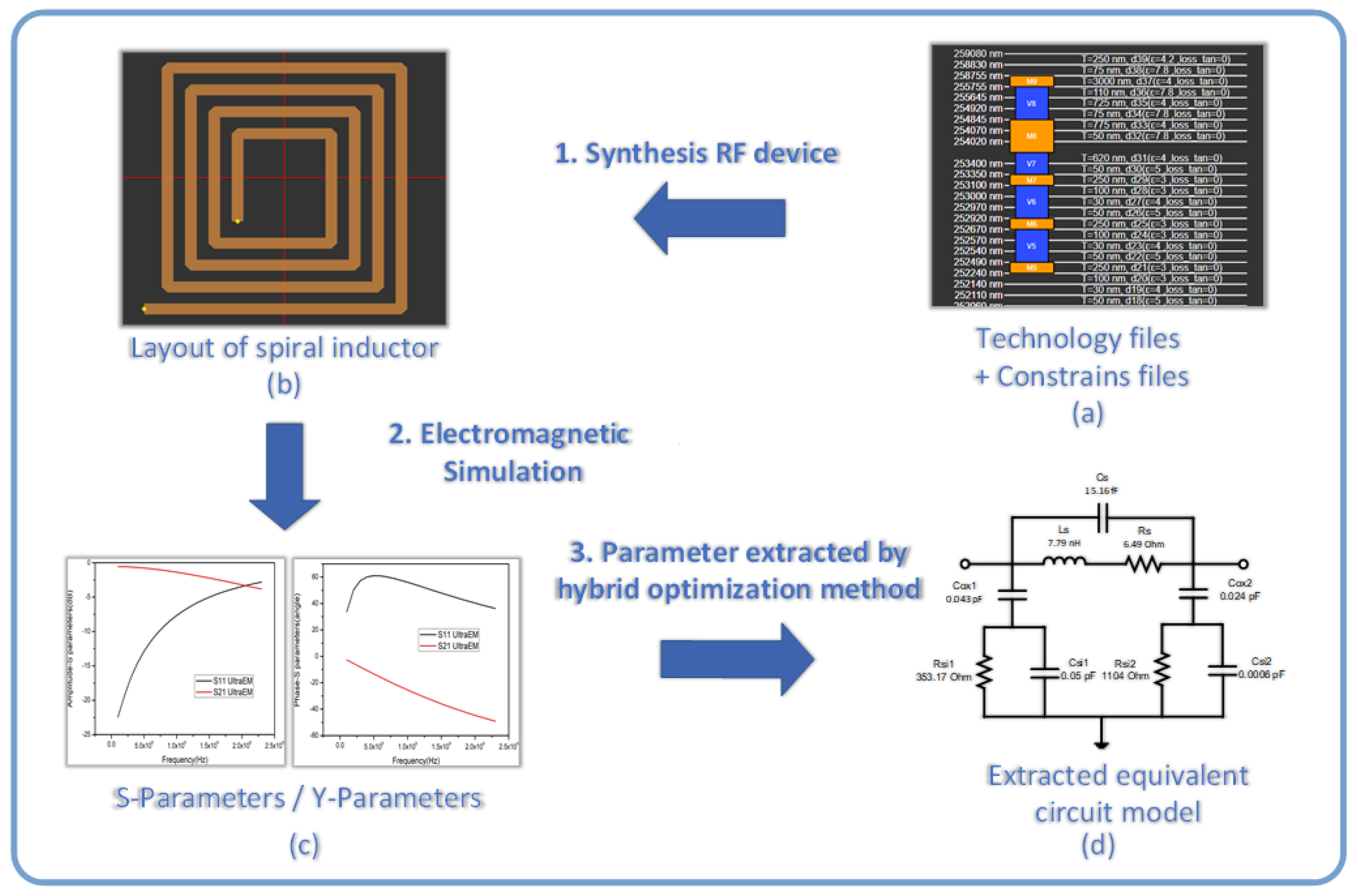
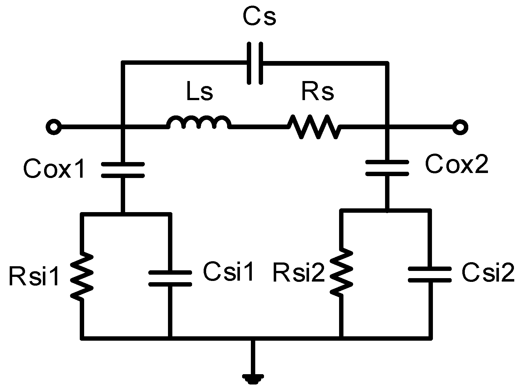
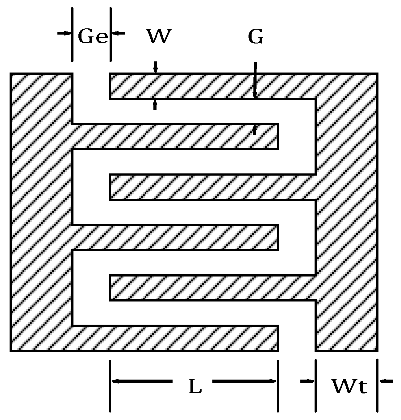
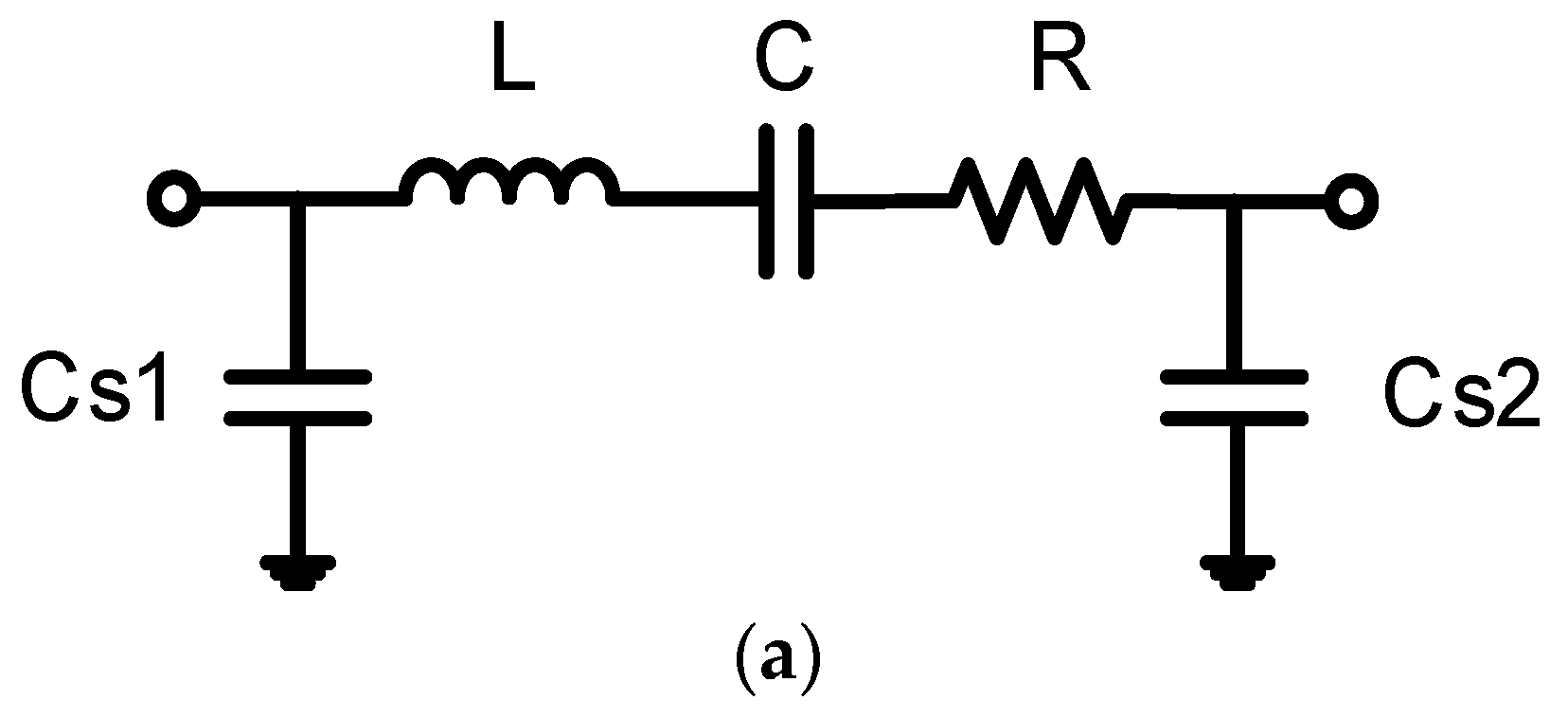
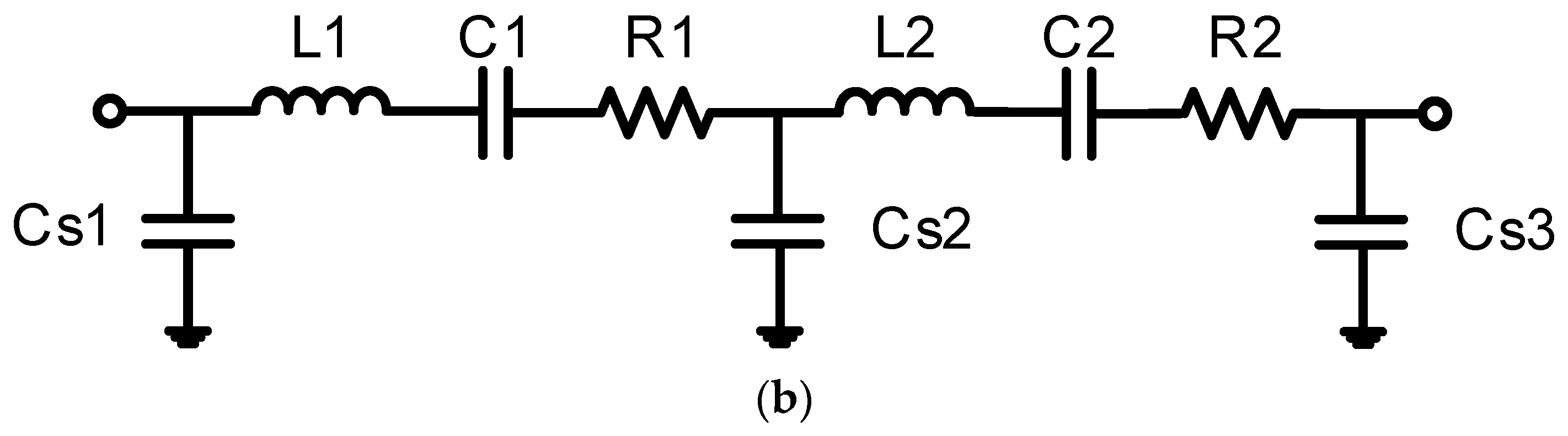
The proposed hybrid optimization method can be applied for modelling components of RFICs. For example, as shown in Figure 1, the layout of a planar spiral inductor is synthesized using technique files, constrains files and so on. The EM simulation results (Figure 1c) of the planar spiral inductor is used as the target of the equivalent circuit. The value of every equivalent circuit (Figure 1d) element is able to be extracted from the proposed method effectively, and the model of the equivalent circuit can be applied for circuit design.
The process of the proposed hybrid GA–Powell’s method can be divided into two parts: global search process and local optimization process.

2.1. Global Search Process

GA is able to search in multiple regions among a solution space simultaneously. Thus, it reduces the possibility of the algorithm falling into local minima, and makes the GA have better global search ability.
Roulette wheel selection [21] is herein used as the selection method of GA. Assuming the population size is N and the fitness of the individual x i is f( x i ), the probability of selection of individual x i is defined as:
P ( x i ) = f ( x i ) j = 1 N f ( x i ) ,
and the cumulative probability is calculated by:
q i = j = 1 i P ( x i ) .
Then, a random number r with a uniform distribution of 0–1 is generated. If q i 1 r q i , the individual x i is selected to enter a new group of the next generation. This process will be repeated until the number of individuals in the new group is equal to the size of the parent group.
The crossover process [22] is based on the following two formulas:
{ x A t + 1 = α x B t + ( 1 α ) x A t x B t + 1 = α x A t + ( 1 α ) x B t
where x A t + 1 and x B t + 1 are individuals after the crossover process, x A t and x B t are two individuals randomly selected, and α is a constant of the crossover with a value between 0 and 1 ( α is herein set as 0.8).
The mutation process [23] is based on:
x A t + 1 = { x A t + k ( x m a x x A t ) r , p i c k > 0.5 x A t k ( x A t x m i n ) r , p i c k 0.5
where x A t + 1 is the individual after the mutation, x A t is the individual before the mutation, k is a constant of the variation with a value between 0 and 1 (herein, k is set as 0.1 to maintain the diversity of population), x m a x is the upper limit of the individual, x m a x is the lower limit of the individual, and r is a random number. Note that pick is a random number with a uniform distribution in the range of 0 to 1. When pick > 0.5, choose the first formula; when pick 0.5, choose the second formula [24].
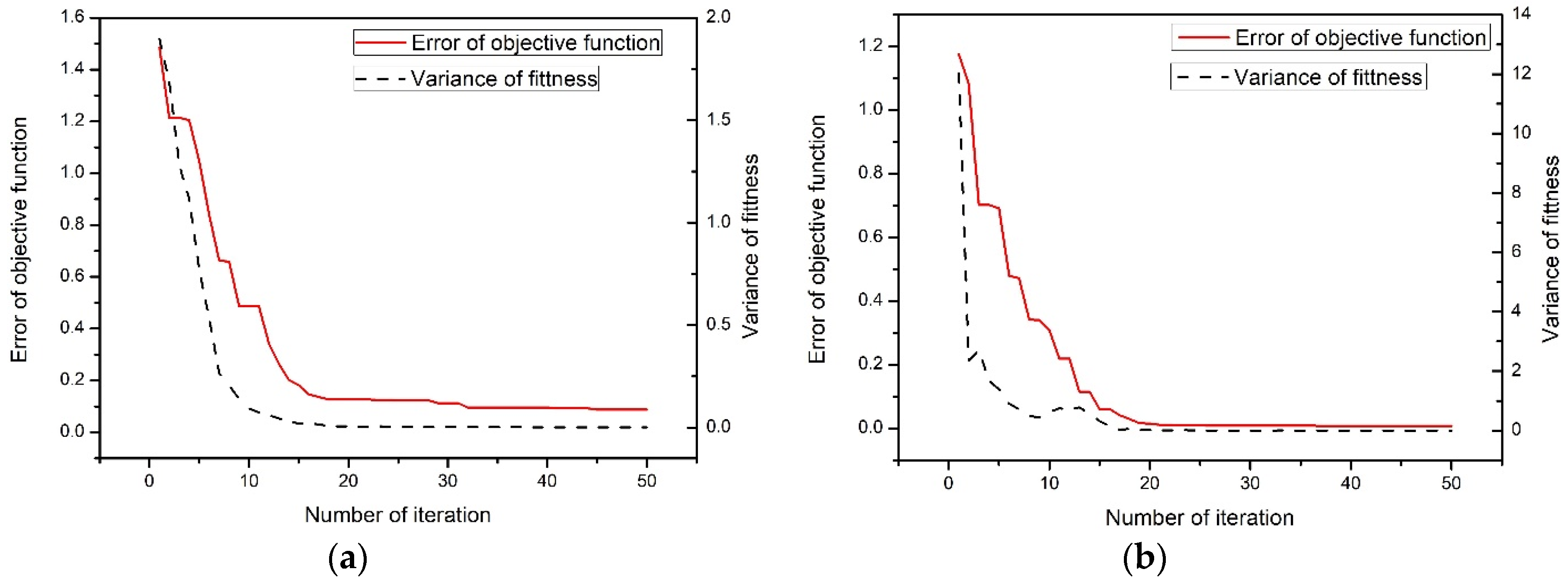
With the iterations of GA, the solution can gradually converge to the global minimum. To accelerate the convergence, a local optimization process is applied when the convergence rate of GA slows down. To determine when to start the local optimization process, the variance of the fitness of population is defined as:
v a r ( f i t ) = 1 n 1 i = 1 n ( f i t i f i t ¯ )
When the optimization converges to an optimum solution, the variance of the fitness for a population is small. Otherwise, the population is scattered in the solution space, and the variance of the fitness is large. When the variance of the fitness is small, the convergence rate consequently slows down, in which it may take many iterations for the mutation process of GA to generate a new individual that has a better fitness than the previous generations. Hence, the local optimization is applied, once the variance of the fitness defined by Equation (5) is small. The CG search method is the most effective way to solve a local optimization problem.

2.2. Local Optimization Process

After global search of GA, the individual with best fitness is chosen as starting point of Powell’s method, which is defined as X 0 ( 1 ) .
(1)
Set an optional initial point X ( 0 ) = X 0 ( 1 ) , and set the convergence thresholds as ε 1   and   ε 2 (herein, ε 1 and ε 2 are both set as 1 × 10⁻⁴). Use the initial basic direction group as the unit coordinate vector, which can be defined as:
S i ( k ) = e i   ( i = 1 ,   2 ,   ,   n )
where e i is the i-th unit coordinate vector, and S i represent the i-th search direction, and k denotes the k-th iteration round.
(2)
Implement one-dimensional search along S i ( k ) (i = 1, 2, …, n), and generate X i ( k ) (i = 1, 2, …, n) from X i 1 ( k ) (i = 1, 2, …, n) at each direction search. The final point X n ( k ) will make the function of f ( X n ( k ) ) have the minimum value. Construct a new search direction:
S ( k ) = X n ( k ) X 0 ( k ) .
Then, perform a one-dimensional search in direction S ( k ) to generate a minimum point X n + 1 ( k ) .
(3)
If
| X n + 1 ( k ) X 0 ( k ) | < ε 1 ,
or
| f ( X n + 1 ( k ) ) f ( X 0 ( k ) ) | < ε 2 | f ( X n + 1 ( k ) ) | ,
stop the iteration and export the optimal solution X n + 1 ( k ) and f( X n + 1 ( k ) ). Otherwise, go to step 4.
(4)
Calculate
f ( X i ( k ) )   ( i = 1 ,   2 ,   ,   n ) ,
Δ m ( k ) = max { f ( X i 1 ( k ) ) f ( X i ( k ) ) } , ( i = 1 ,   2 ,   , n ) ,
where m denotes the corresponding index at which f ( X m 1 ( k ) ) f ( X m ( k ) ) is the maximum one among { f ( X i 1 ( k ) ) f ( X i ( k ) ) }   ( i = 1 ,   2 ,   , n ) . Then, the direction that contributes the most in the k-th iteration round is:
S m ( k ) = X m ( k ) X m 1 ( k ) .
(5)
To ensure that the search direction group for each iteration is linearly independent, it is needed to determine whether the original search direction group can be directly used as the search direction group in the next iteration.
Firstly, determine mapping points:
X ( k ) = 2 X n ( k ) X 0 ( k ) ,
then calculate f ( X ( k ) ) and set:
f 1 = f ( X 0 ( k ) ) ,   f 2 = f ( X n ( k ) ) ,   f 3 = f ( X ( k ) ) .
If f 3 < f 1 and
( f 1 2 f 2 + f 3 ) ( f 1 f 2 Δ m ( k ) ) 2 < 0.5 Δ m ( k ) ( f 1 f 3 ) 2 ,
go to step 6, and replace the most contributing search direction from Equation (12) with the new search direction. Otherwise, go to step 7.
(6)
Set the starting point and the search direction group of the (k + 1)-th iteration as follows:
X 0 ( k + 1 ) = X n + 1 ( k ) ,
S i ( k + 1 ) ( i =   1 ,   2 ,   ,   n ) = { S 1 ( k ) ,   ,   S m 1 ( k ) ,   S ( k ) ,   S m + 1 ( k ) ,   ,   S n ( k ) } ,
and replace the most contributing search direction S m ( k ) with the new search direction S ( k ) . Then, set k = k + 1 and go to step 2.
(7)
Set the starting point and the search direction group of the (k + 1)-th iteration as follows:
If f 2 < f 3 ,
X 0 ( k + 1 ) = X n ( k ) .
Otherwise
X 0 ( k + 1 ) = X ( k ) ,
S i ( k + 1 ) = S i ( k )   ( i =   1 ,   2 ,   ,   n ) .
Set k = k + 1, and go to step 2 [14].
After the local optimization process, the solution is able to converge to an appropriate and accurate global minimum. This hybrid method combines the advantages of the global search ability of GA and the high accuracy and fast convergence of Powell’s method in the local search.

2.3. RF Device Modeling

The modeling process is shown in Figure 2. The full-wave simulation result of the layout of an RF component is obtained by UltraEM®, and the corresponding Y-parameters are labeled as Y E M . By using a Spice simulator, the Y-parameters of the equivalent circuit can be obtained from the calculated port voltage and current, viz:
I = Y V ,
where Y is an N × N matrix, and V and I are the port voltage vector and the port current vector, respectively. The entry of the Y-matrix is defined as:
Y n m = I n V m | V k = 0   f o r   k m .
If the voltage of the excited port is set as 1 volt, the Y-parameters are equal to the port currents, viz:
Y n m = I n .
Label the Y-parameters simulated from the equivalent circuit as Y s p i c e 
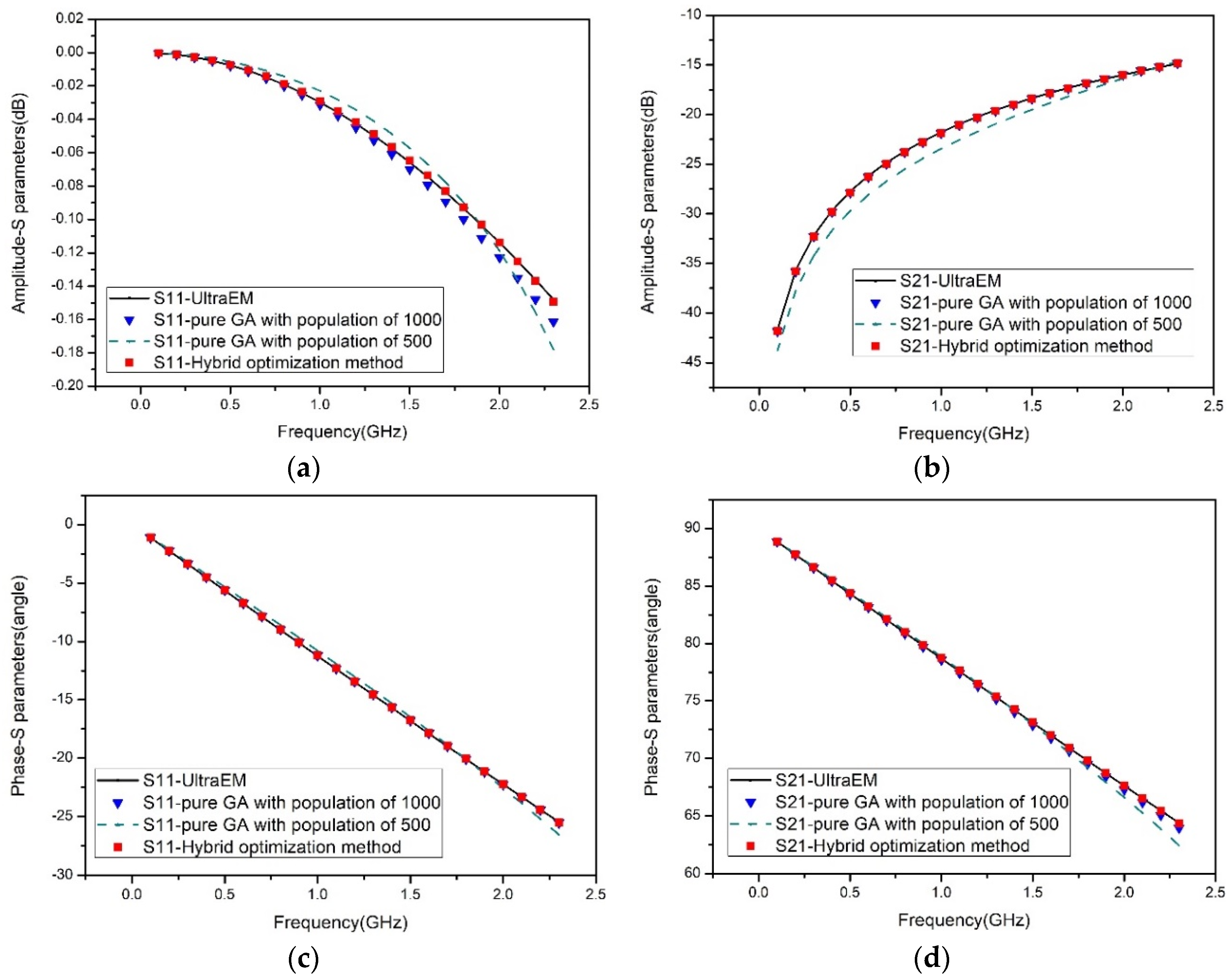
. In order to fit the result of the equivalent circuit with the accurate EM simulation, the objective function to be optimized can be defined as:
o b j ( Y s p i c e , Y E M ) = i = f s f e m = 1 N n = 1 N | ( Y E M m n ) i ( Y s p i c e m n ) i | ,
where N is the port number of the device; fs and 
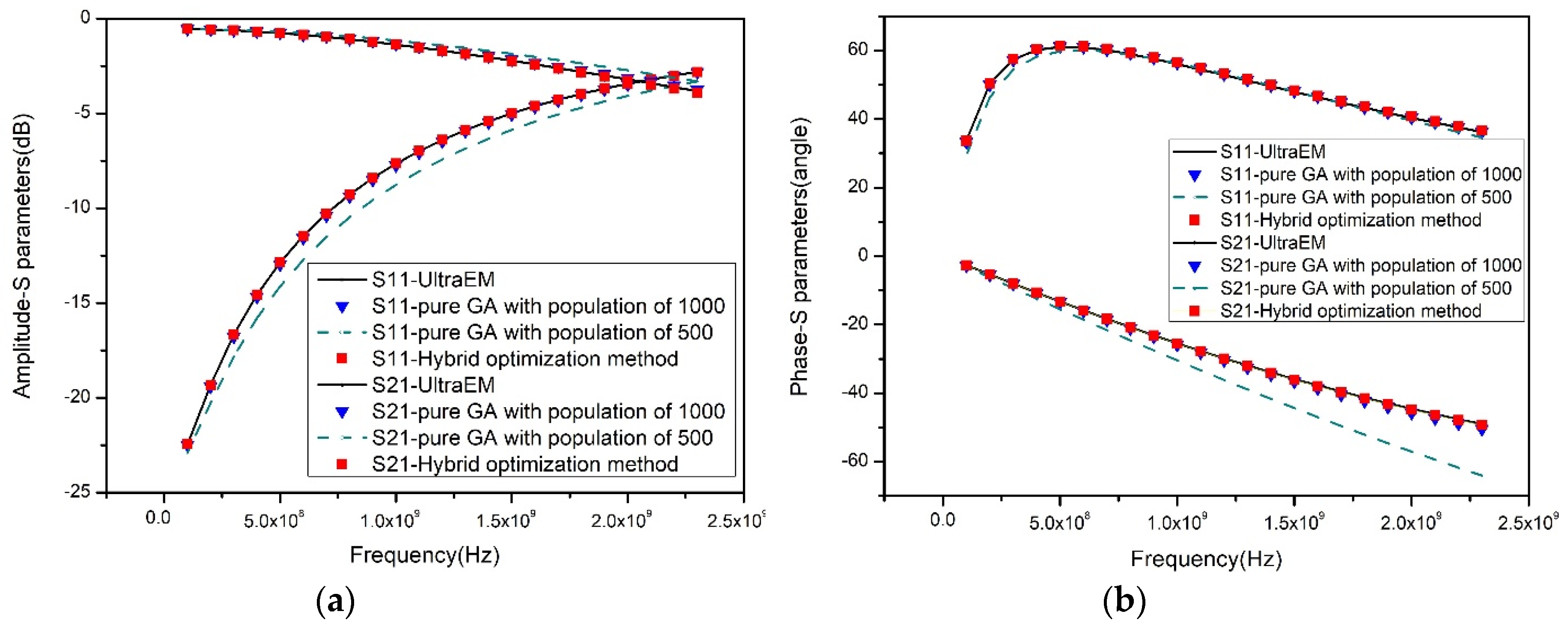
fe represent the start and the end frequencies of simulation, respectively. To verify the effect of the method proposed in Section 2, a planar spiral inductor and a microstrip interdigital capacitor were tested.

3. Results and Discussions

In order to illustrate the effectiveness of this hybrid method, a planar spiral inductor and a microstrip interdigital capacitor are used as examples. The interested frequency range is assumed to be from 0.1 GHz to 2.3 GHz. Both examples are modeled by (1) pure GA with 500 individuals; (2) pure GA with 1000 individuals; and (3) Hybrid GA–Powell’s method (including 500 individuals of GA). In order to ensure accuracy and efficiency of the global search process in the hybrid optimization method, the initial population of GA in the hybrid optimization is set as 500. In order to validate accuracy and efficiency of the hybrid optimization method, the initial population of the pure GA is set as 500 and 1000 for comparison. For all these three cases, the local optimization process is started after v a r ( f i t ) < v (0.001) herein.

3.1. Planar Spiral Inductor

The planar spiral inductor is fabricated on a substrate with dielectric constant of 11.9 and thickness of 750 microns. The thickness and conductivity of the metal are 2 microns and 2.8 × 10⁷ S/m respectively. The layout of the planar spiral inductor is shown in Figure 3, where the geometrical parameters are shown in Table 1.
The lumped equivalent circuit of the planar spiral inductor [6] to be modelled by hybrid GA–Powell’s method is shown in Figure 4.
With the three aforementioned settings, the errors of objective function for the planar spiral inductor are plotted in Figure 5, whereas the final errors and time costs are listed in Table 2. The initial population of the global search process in the hybrid GA–Powell’s method is the same as the pure GA method with 500 individuals. From Figure 5, one can see that the convergence rate of the pure GA optimization gradually slows down after 22 iterations. For the hybrid GA–Powell’s method, the local optimization is applied after the global search.
In Table 2, it can be observed that for the hybrid GA–Powell’s method with seven iterations of the local optimization process after the global search, the error finally drops to 1.4157 × 10⁻². In contrast, when using 50 iterations of pure GA with 500 and 1000 individuals, the errors are still 1.7347 × 10⁻¹ and 2.03798 × 10⁻², respectively. Moreover, the total times costed by the aforementioned process for the three settings are 574 s, 1197 s and 378 s, respectively.
To validate the accuracy of the proposed method, the S-parameters calculated by the full-wave simulation of the layout using UltraEM® and the circuit simulation of the equivalent circuit extracted by the three optimization methods are compared in Figure 6, while the extracted parameters are shown in Table 3. The circuit simulation results using setting 1 cannot match the full-wave results, but the results using setting 3 agree very well with the full-wave results.

3.2. Microstrip Interdigital Capcitor

The microstrip interdigital capacitor is fabricated on a substrate with dielectric constant of 12.9, loss tangent of 0.001, and thickness of 100 microns. The conductivity of the metal is 2.8 × 10 7 S/m. The layout of microstrip interdigital capacitor is shown in Figure 7, where the geometrical parameters of the parameters are shown in Table 4.
The lumped equivalent circuit of the microstrip interdigital capacitor [25] to be modelled by hybrid GA–Powell’s method is shown in Figure 8a,b. The equivalent circuit in Figure 8a is used for lower frequency applications, while the equivalent circuit in Figure 8b is used for higher frequency.
The interdigital capacitor is also modelled using the aforementioned three settings. The errors of objective function are shown in Figure 9. It is observed that after 31 iterations the convergence of the global search becomes slow, where the hybrid method starts the local optimization process and can rapidly converge to a small error.
The final errors and time costs are shown in Table 5. In the hybrid GA–Powell’s method, eight iterations of the local optimization process are implemented after 30 iterations of the global search process, and the error finally drops to 1.45255 × 10⁻⁴. Compared with the pure GA in which the errors using 50 iterations with 500 and 1000 individuals are 8.324 × 10⁻³ and 1.16 × 10⁻³, respectively, the results of the proposed method are much better. In regard to the total time cost, because the proposed method only spends 38 iterations to converge, it costs only 412 s. In contrast, the pure GA methods using 50 iterations with 500 and 1000 individuals spend 529 s and 1079 s, respectively, yet still have larger errors than the proposed method.
The extracted parameters using these three methods are listed in Table 6. The full-wave results and the circuit simulation results are both shown in Figure 10. The circuit simulation results using setting 1 cannot match the full-wave results. For the results of setting 2, the amplitude of S11 cannot match the full-wave results. In sharp contrast, the results using setting 3 agree very well with the full-wave results. The accuracy of the hybrid GA–Powell’s method is validated once again.

3.3. More Discussions

To determine the appropriate starting point of the local optimization process, the variance of the fitness of population is used. The error of objective function and the variance of the fitness of population in each generation are recorded. It is clearly shown in Figure 11, when the variance of the fitness of population becomes small, the convergence rate of GA slows down. After the variance of the fitness of the population drops to 0.001, the error reduction of the objective function becomes very slow. Hence, the variance of the fitness of the population can be employed to effectively determine the starting point of the local optimization process. As is shown in Figure 12, after a full 50 iterations of GA, the local optimization process successful finds the appropriate global minimum for both examples. However, if only 10 iterations of GA are used, the local optimization process is trapped at a local minimum. For the proposed method, the local optimization process starts when v a r ( f i t ) < v (0.001). By so doing, this proposed method can successfully achieve the global minimum (i.e., without being trapped in a local minimum) and yet save much time from unnecessary iterations of the global search process. The errors of the objective function by the three different hybrid optimization methods stated above are shown in Table 7.

4. Conclusions

In order to efficiently determine the circuit elements of the equivalent circuit model, a hybrid GA–Powell’s method has been proposed. This method combines the merits of the global search ability of GA and the local search capability of Powell’s method with good accuracy and rapid convergence. The variance of the fitness of population has been introduced as a key criterion to effectively determine the starting point of the local optimization process. This hybrid method is able to effectively search the global minimum of a parameter extraction problem. The planar spiral inductor and microstrip interdigital capacitor have been used as design examples to validate the accuracy and efficiency of this method. Some problems, such as very wide-band parameter extraction, may not be tackled by the proposed method. In our ongoing research, the equivalent circuit topology could be adjustable adaptively (e.g., increasing the order of ladder model) so as to maintain the modeling accuracy in a very wide frequency band, which will be reported sometime in the near future.

Author Contributions

Conceptualization, Z.G., P.Z. and G.W.; Data curation, Z.G.; Funding acquisition, G.W.; Investigation, Z.G., Q.L. and X.W.; Methodology, Z.G.; Project administration, G.W.; Supervision, G.W.; Writing—original draft, Z.G.; Writing review & editing, Z.G., P.Z. and G.W.

Funding

This work was supported in part by the Natural Science Foundation of China under Grant 61601163, in part by the Zhejiang Provincial Key Research & Development Project under Grant 2019C04003.

Conflicts of Interest

The authors declare no conflicts of interest.

References

  1. Burghartz, J.N.; Edelstein, D.C.; Soyuer, M.; Ainspan, H.A.; Jenkins, K.A. RF circuit design aspects of spiral inductors on silicon. IEEE J. Solid State Circuits 1998, 3, 2028–2034. [Google Scholar] [CrossRef]
  2. Karisan, Y.; Caglayan, C.; Trichopoulos, G.C.; Sertel, K. Lumped-element equivalent-circuit modeling of millimeter-wave HEMT parasitics through full-wave electromagnetic analysis. IEEE Trans. Microw. Theory Tech. 2016, 64, 1419–1430. [Google Scholar] [CrossRef]
  3. Issakov, V.; Kehl-Waas, S.; Breun, S. Analytical equivalent circuit extraction procedure for broadband scalable modeling of three-port center-trapped symmetric on-chip inductor. IEEE Trans. Circuits Syst. 2019, 66, 3557–3570. [Google Scholar] [CrossRef]
  4. Zhao, P.; Chan, C.H. Design and analysis of a high-selectivity frequency-selective surface at 60 GHz. IEEE Trans. Microw. Theory Tech. 2016, 64, 1694–1703. [Google Scholar]
  5. Cao, Y.; Wang, G. A wideband and scalable model of spiral inductor using space-mapping neural network. IEEE Trans. Microw. Theory Tech. 2007, 55, 2473–2480. [Google Scholar] [CrossRef]
  6. Cao, Y.; Groves, R.A.; Huang, X.; Zamdmer, N.D.; Plouchart, J.O.; Wachnik, R.A.; Hu, C. Frequency-independent equivalent circuit model for on-chip spiral inductors. IEEE J. Solid State Circuits 2003, 38, 419–426. [Google Scholar] [CrossRef]
  7. Alley, G.D. Interdigital capacitors and their application on lumped-element microwave integrated circuits. IEEE Trans. Microw. Theory Tech. 1970, 18, 1028–1033. [Google Scholar] [CrossRef]
  8. Ghayekhloo, A.; Afsahi, M.; Orouji, A.A. An optimized checkerboard structure for cross-section reduction: Producing a coating surface for bistatic radar using the equivalent electric circuit model. IEEE Antennas Propag. Mag. 2018, 60, 78–85. [Google Scholar] [CrossRef]
  9. Watts, J.; Bittner, C.; Heaberlin, D.; Hoffmann, J. Extraction of compact model parameters for ULSI MOSFET using a genetic algorithm. In Proceedings of the 2nd International Conference on Modeling and Simulation of Microsystems, Cambridge, MA, USA, 19 April 1999; pp. 176–179. [Google Scholar]
  10. Yun, I.; May, G.S. Passive circuit model parameter extraction using genetic algorithms. In Proceedings of the 49th Electronic Components and Technology Conference, San Diego, CA, USA, 1–4 June 1999. [Google Scholar]
  11. Michalewicz, Z.; Janikow, C.Z.; Krawczyk, J.B. A modified genetic algorithm for optimal control problems. Comput. Math. Appl. 1992, 23, 83–94. [Google Scholar] [CrossRef] [Green Version]
  12. Diaz-Gomez, P.A.; Hougen, D.F. Initial population for genetic algorithm: A Metric Approach. In Proceedings of the GEM 2007, Las Vegas, NV, USA, 25–28 June 2007. [Google Scholar]
  13. Srinivas, M.; Patnaik, L.M. Adaptive probabilities of crossover mutation in genetic algorithms. IEEE Trans. Syst. Man Cybern. 1994, 24, 656–667. [Google Scholar] [CrossRef]
  14. Powell, M.J.D. An efficient method for finding the minimum of a function of several variables without calculating derivatives. Comput. J. 1964, 7, 155–162. [Google Scholar] [CrossRef]
  15. Keifer, J. Sequential minimax search for a maximum. Proc. Am. Math. Soc. 1953, 4, 502–506. [Google Scholar] [CrossRef]
  16. Fletcher, R.; Powell, M.J.D. A rapidly convergent descent method for minimization. Comput. J. 1963, 2, 163–168. [Google Scholar] [CrossRef]
  17. Wang, J.; Kusiak, A. Computational Intelligence in Manufacturing Handbook; CRC Press: Boca Raton, FL, USA, 2000. [Google Scholar]
  18. Faraday Dynamics, Ltd. Available online: http://www.faradynamics.com (accessed on 30 September 2018).
  19. Hansen, M.C.; Yalcin, H.; Hayes, J.P. Unveiling the ISCAS-85 benchmarks: A case study in reverse engineering. IEEE Des. Test 1999, 16, 72–80. [Google Scholar] [CrossRef]
  20. Van Nechel, E.; Ferranti, F.; Rolain, Y.; Latatire, J. A wide-band equivalent circuit model for single slot defected ground structures. In Proceedings of the 2019 IEEE 23rd Workshop on Signal and Power Integrity (SPI), Chambéry, France, 18–21 June 2019. [Google Scholar]
  21. Holland, J. Adaptation in Natural and Artificial Systems; University of Michigan Press: Ann Arbor, MI, USA, 1975. [Google Scholar]
  22. Larranaga, P.; Kuijpers, C.M.; Murga, R.H.; Yurramendi, Y. Learning Bayesian Network Structures by searching for the best ordering with genetic algorithms. IEEE Trans. Syst. Man Cybern. 1994, 26, 487–493. [Google Scholar] [CrossRef]
  23. Patil, S.; Bhende, M. Comparison and Analysis of different mutation strategies to improve the performance of genetic algorithm. Int. J. Comput. Sci. Inf. Technol. 2014, 5, 4669–4673. [Google Scholar]
  24. Bodenhofer, U. Real-Coded Gas. In Genetic Algorithms: Theory and Application, Lecture Note Third Edition—Winter 2003/2004; Bodenhofer, U., Ed.; SCCH: Hagenberg, Austria, 2004; Chapter 5; pp. 59–61. [Google Scholar]
  25. Beeresha, R.S.; Khan, A.M.; Manjunath-Reddy, H.V. Design and optimization of interdigital capacitor. Int. J. Res. Eng. Technol. 2016, 5, 73–78. [Google Scholar]
Figure 1. Parameter extraction application of hybrid optimization method.
Electronics 08 01133 g001
Figure 2. Flow chart model of the hybrid GA–Powell’s method.
Electronics 08 01133 g002
Figure 3. Geometrical layout of the planar spiral inductor.
Electronics 08 01133 g003
Figure 4. Equivalent circuit of the planar spiral inductor.
Electronics 08 01133 g004
Figure 5. Error of objective function of the planar spiral inductor. Solid line represents the error of Hybrid GA–Powell’s method. Dash-dot line represents error of pure GA with population of 500. Dash line represents error of pure GA with population of 1000.
Electronics 08 01133 g005
Figure 6. Comparison of S-parameters of the planar spiral inductor between UltraEM® simulation and equivalent circuit simulation modeled by pure GA with population of 500, pure GA with population of 1000 and hybrid GA–Powell’s method. (a) Amplitude comparison of S-parameters. (b) Phase comparison of S-parameters.
Electronics 08 01133 g006
Figure 7. Geometry layout of the microstrip interdigital capacitor.
Electronics 08 01133 g007
Figure 8. Lumped equivalent circuits for the microstrip interdigital capacitor. (a) Lower frequency; (b) higher frequency.
Electronics 08 01133 g008aElectronics 08 01133 g008b
Figure 9. Error of objective function of the microstrip interdigital capacitor. The logarithmic coordinates are used. Solid line represents the error of Hybrid GA–Powell’s method. Dash-dot line represents error of pure GA with population of 500. Dash line represents error of pure GA with population of 1000.
Electronics 08 01133 g009
Figure 10. Comparison of S-parameters of the microstrip interdigital capacitor between UltraEM® simulation and equivalent circuit simulation modeled by pure GA with population of 500, pure GA with population of 500 and hybrid GA–Powell’s method. (a) Amplitude comparison of S-parameters S11; (b) amplitude comparison of S-parameters S21; (c) phase comparison of S-parameters S11; (d) phase comparison of S-parameters S21.
Electronics 08 01133 g010
Figure 11. Error versus variance of fitness: (a) planar spiral inductor and (b) microstrip interdigital capacitor modeled by pure GA with population of 500.
Electronics 08 01133 g011
Figure 12. Error versus variance of fitness: (a) planar spiral inductor and (b) microstrip interdigital capacitor modeled by hybrid optimization method with three different starting points of local optimization process.
Electronics 08 01133 g012
Table 1. Parameters of planar spiral inductor.
NameValuesUnits
WConductor width13um
SConductor spacing7um
NNumber of turns3integer
L1Length of second outermost segment300um
L2Length of outermost segment300um
Table 2. Error after optimization and time cost of optimization algorithm with the example of planar spiral inductor.
Optimization AlgorithmError after OptimizationNumber of IterationsTime Cost
GAPowell’s Method
Pure GA with 500 population size1.7347 × 10−150NA574 s
Pure GA with 1000 population size2.03798 × 10−250NA1197 s
Hybrid GA–Powell’s method1.4157 × 10−2227378 s
Table 3. Result of planar spiral inductor parameters extraction.
Circuit ComponentsPure GA with Population of 500Pure GA with Population of 1000Hybrid MethodUnits
Rs6.4598 6.47706.4896ohm
Ls7.76927.76627.7860nH
Cs5.078212.712315.161fF
Cox10.12710.04960.0436pF
Csi111.529410.99310.0503pF
Rsi118.376714.0226353.17ohm
Cox20.40240.05570.0243pF
Csi215.63286.38490.000668pF
Rsi222.019722.82861104.1ohm
Table 4. Parameters of microstrip interdigital capacitor.
NameValuesUnits
WFinger width30um
GGap between fingers30um
GeGap at end of fingers30um
LLength of overlapped region600um
NpNumber of finger pairs3integer
WtWidth of interconnect30um
Table 5. Error after optimization, number of iterations and time cost of optimization algorithm with the example of planar spiral inductor.
Optimization AlgorithmError after OptimizationNumber of IterationsTime Cost
GAPowell’s Method
Pure GA with population of 5008.324 × 10−350NA529 s
Pure GA with population of 10001.16 × 10−350NA1079 s
Hybrid GA–Powell’s method1.45255 × 10−4308412 s
Table 6. Results of microstrip interdigital capacitor parameters extraction.
Circuit ComponentsPure GA with Population of 500Pure GA with Population of 1000Hybrid MethodUnits
Cs10.19290.18310.1829pF
L11.56721.23170.5412nH
C0.10300.12890.1304pF
R8.31335.32901.4035ohm
Cs20.19520.18210.1831pF
Table 7. Error of the objective function by three different hybrid optimization methods.
Hybrid Optimization MethodError after Optimization
Planar Spiral InductorMicrostrip Interdigital Capacitor
Local optimization process started when var(fit) < 0.0011.27055 × 10−22.01342 × 10⁻⁴
Local optimization process started after 50 iterations of GA1.42699 × 10−21.66245 × 10⁻⁴
Local optimization process started after 10 iterations of GA0.22868 × 10−11.24562 × 10⁻²

