Synthesis of Rectenna for Powering Micro-Watt Sensors by Harvesting Ambient RF Signals’ Power


Abstract
:1. Introduction
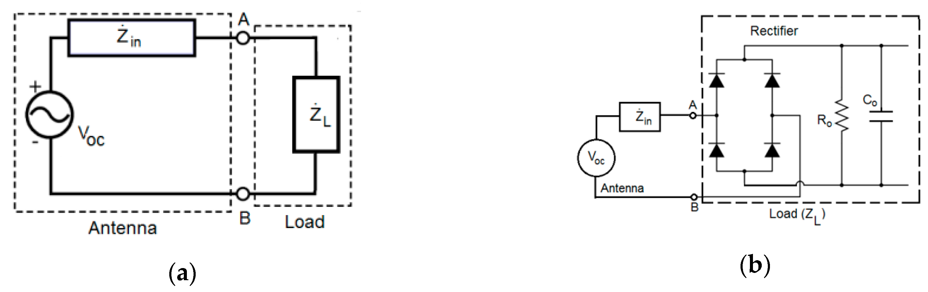
2. The Designed Rectenna and Its Performance
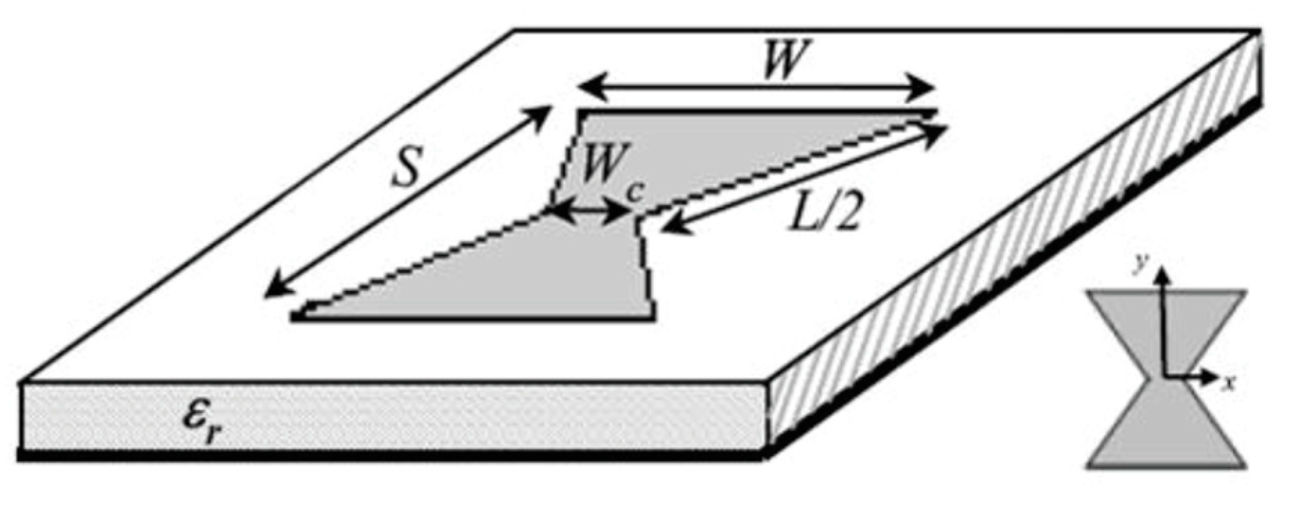
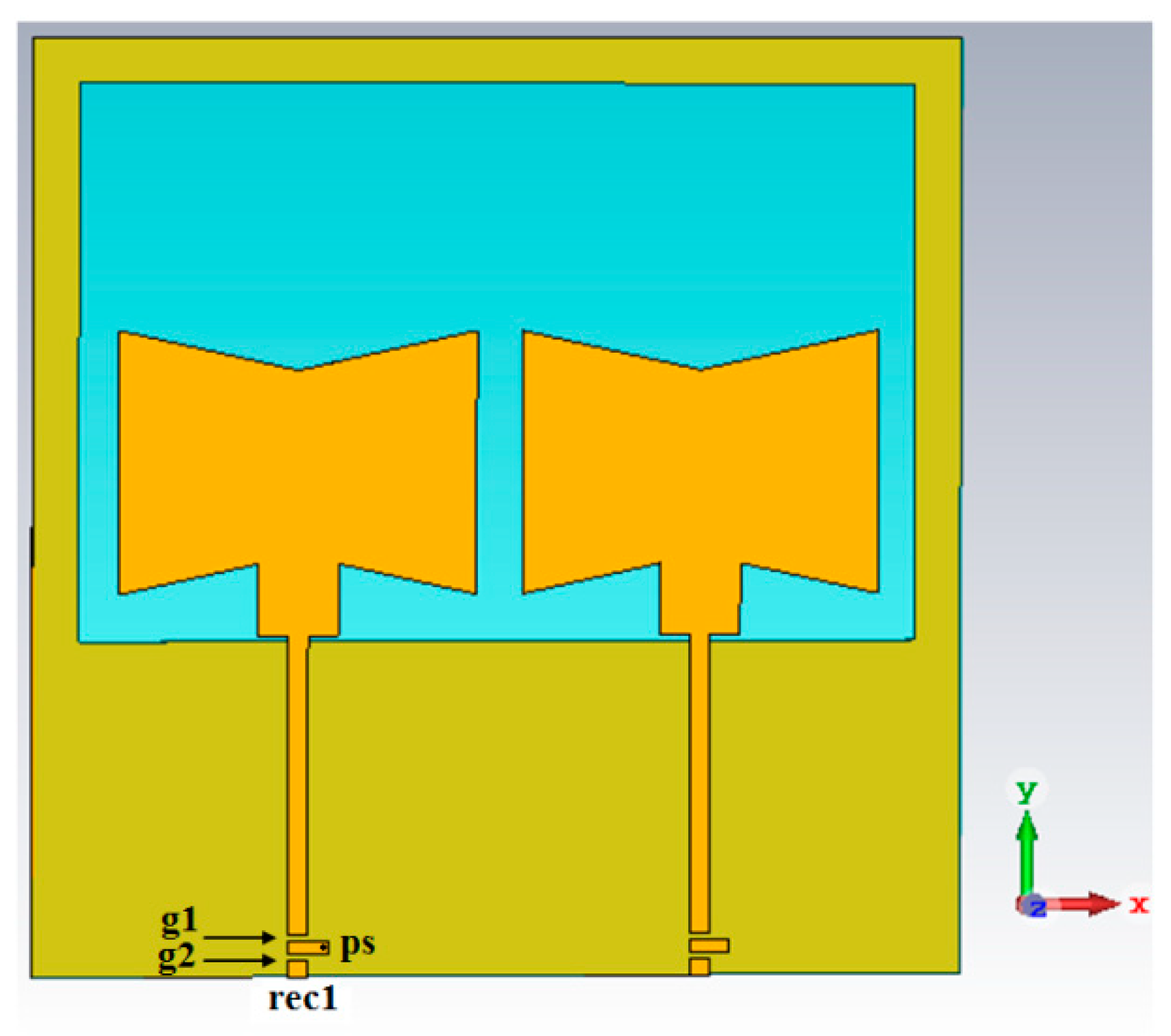
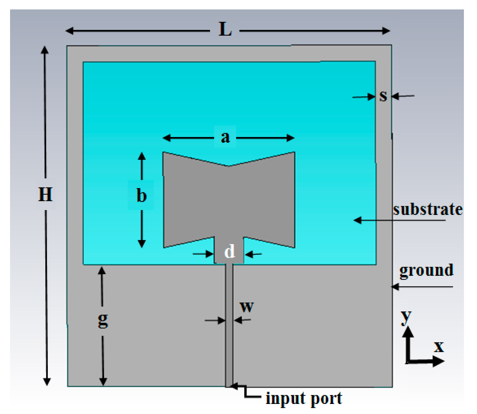
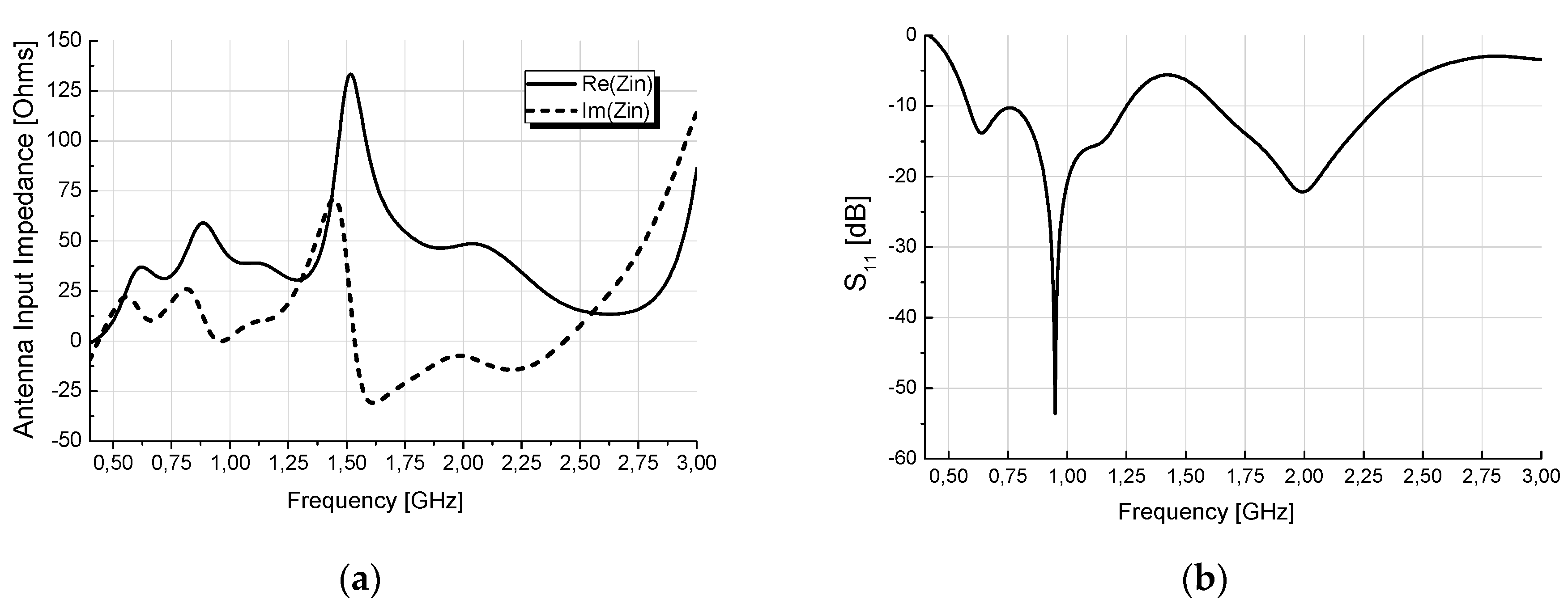
2.1. Antenna_1
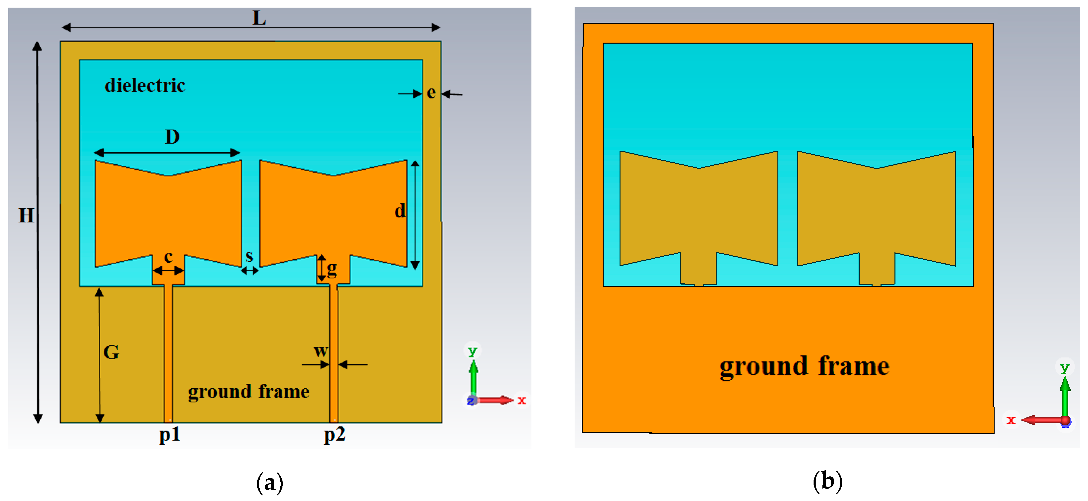
2.2. Antenna_2
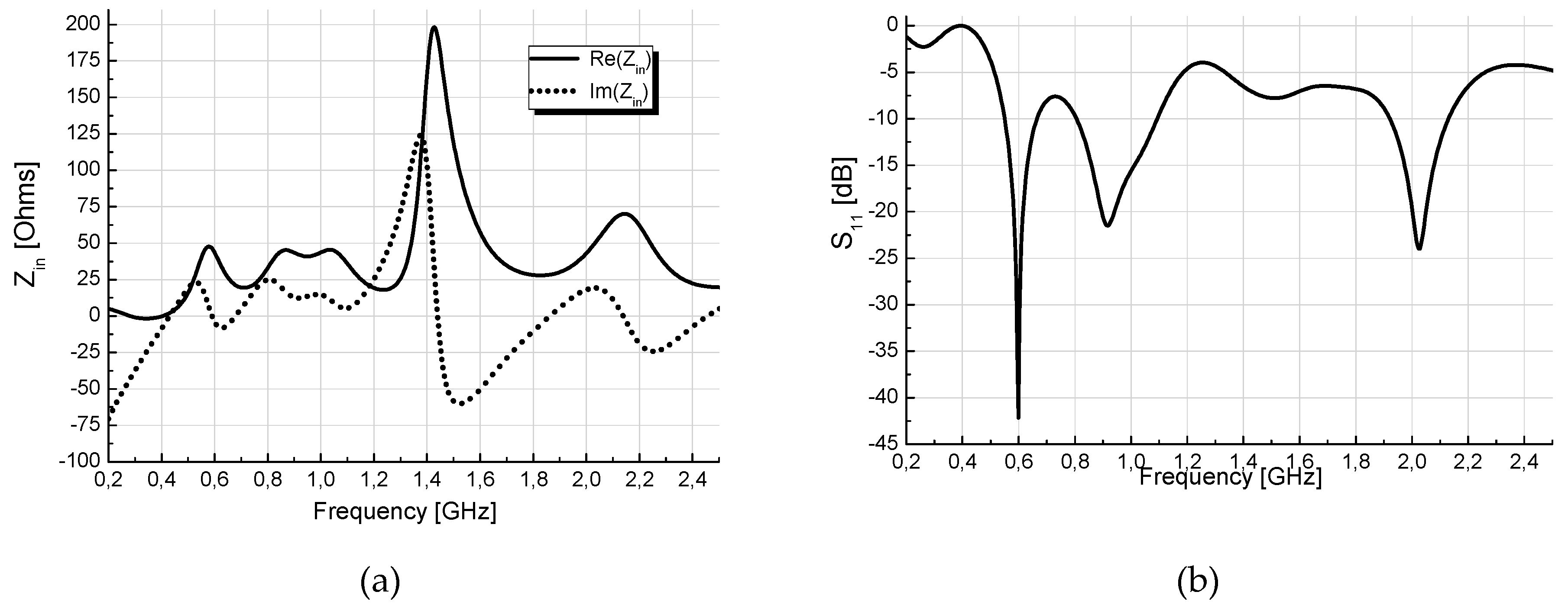
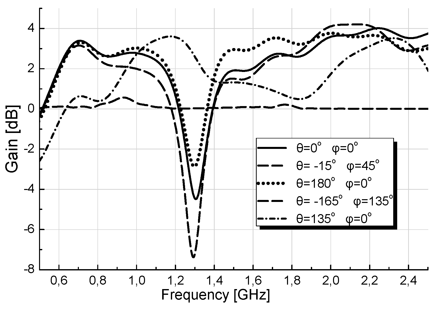
3. Results and Discussion
3.1. Simulation and Calculation Steps
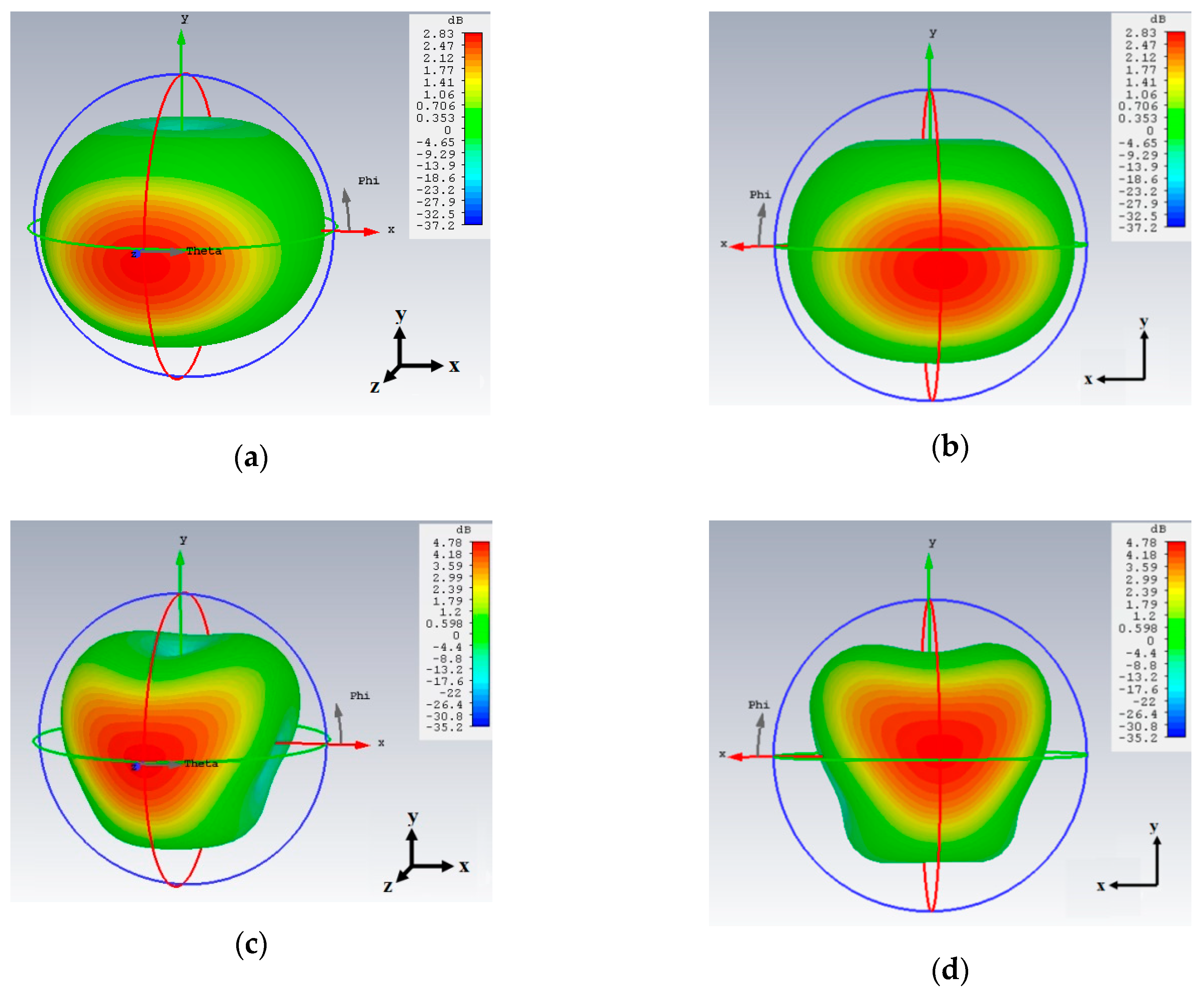
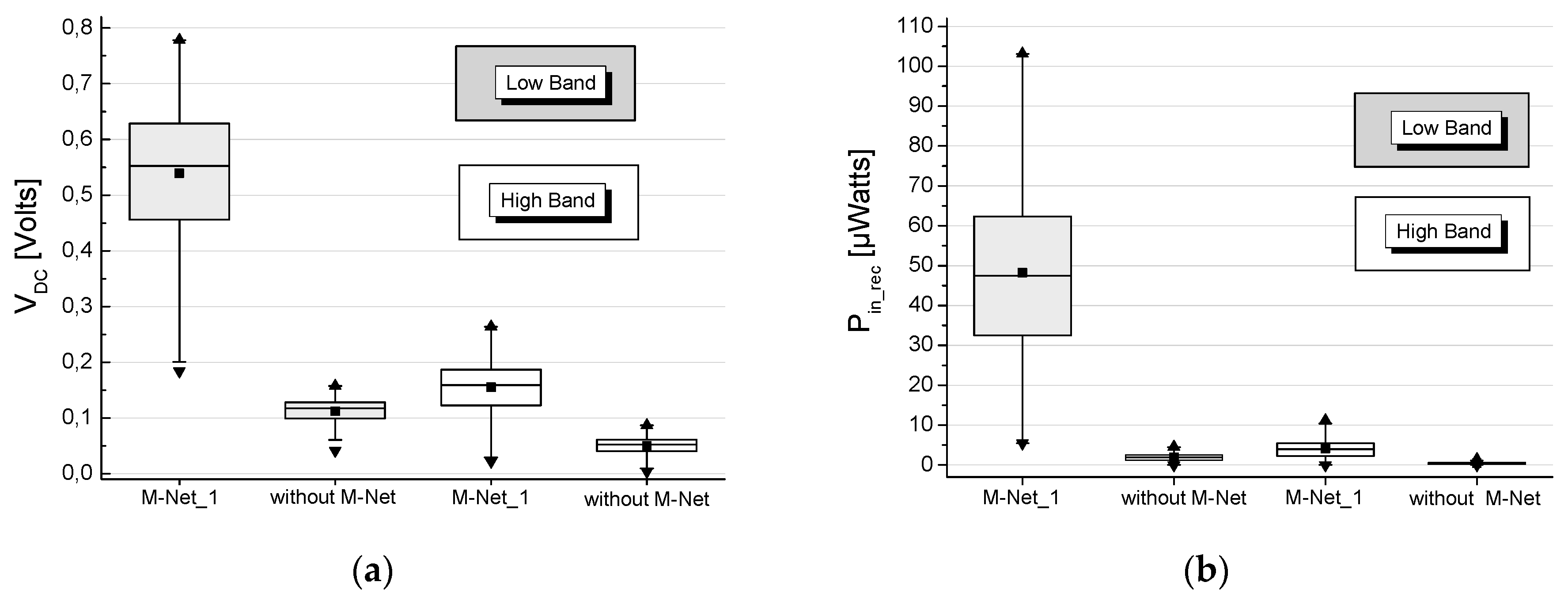
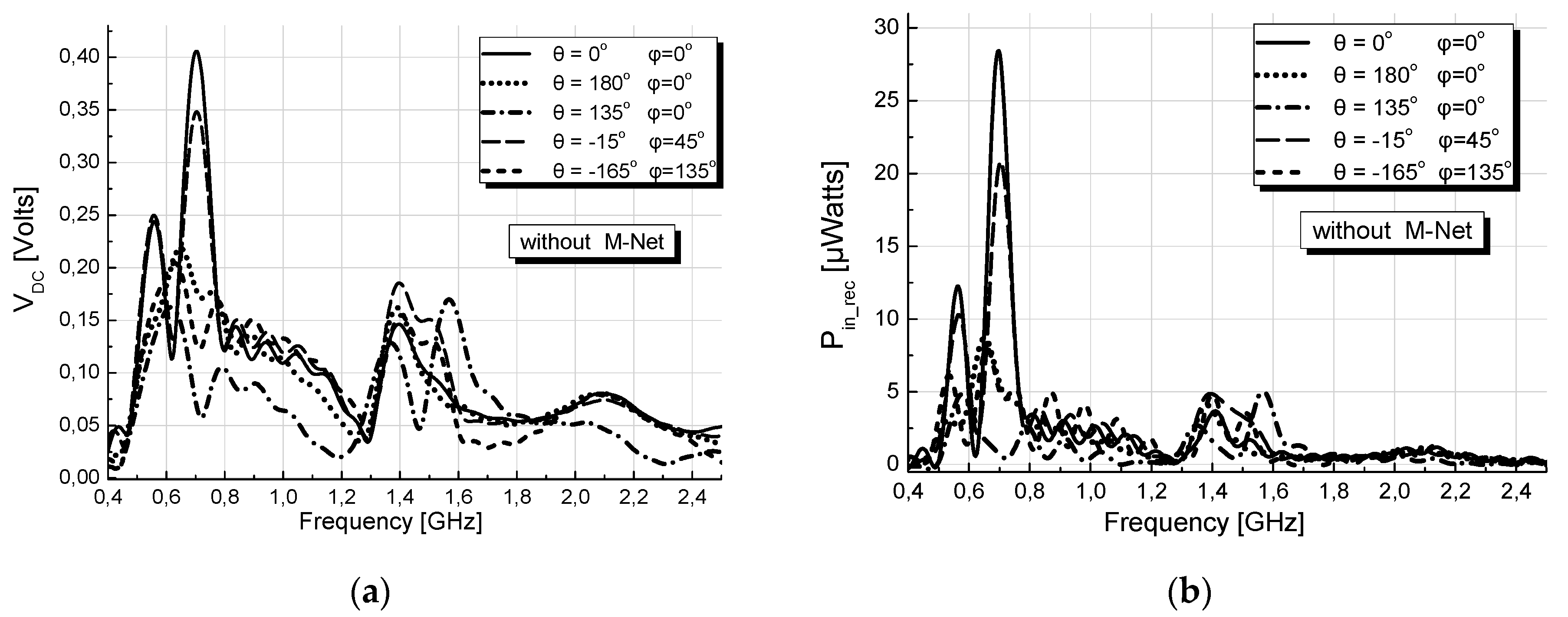
3.2. Results without M-Nets
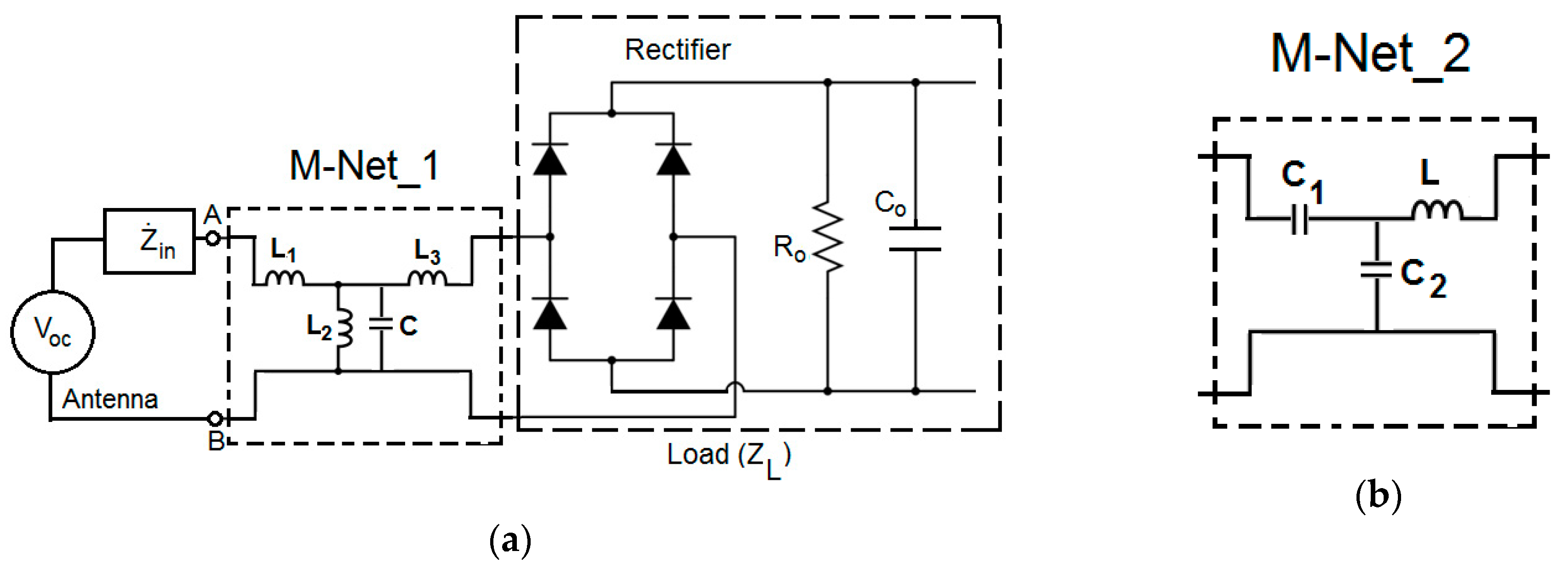
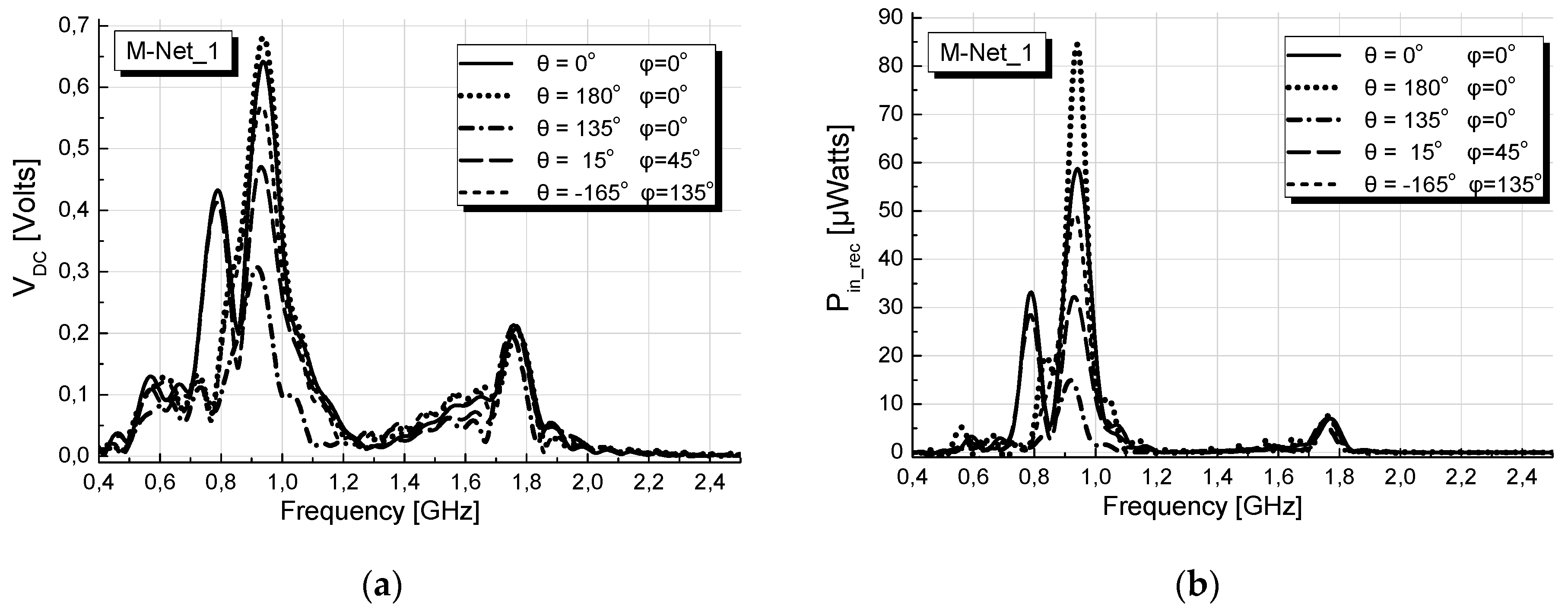
3.3. Results with M-Net_1
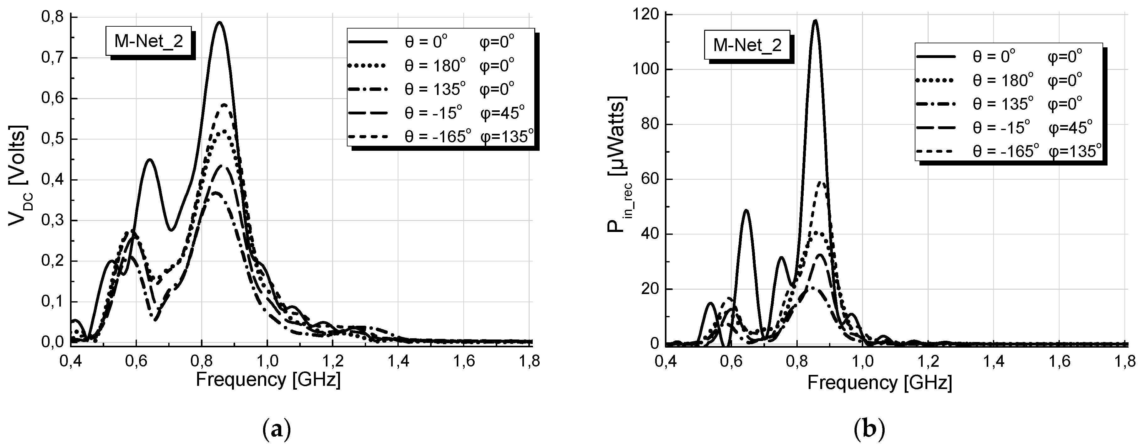
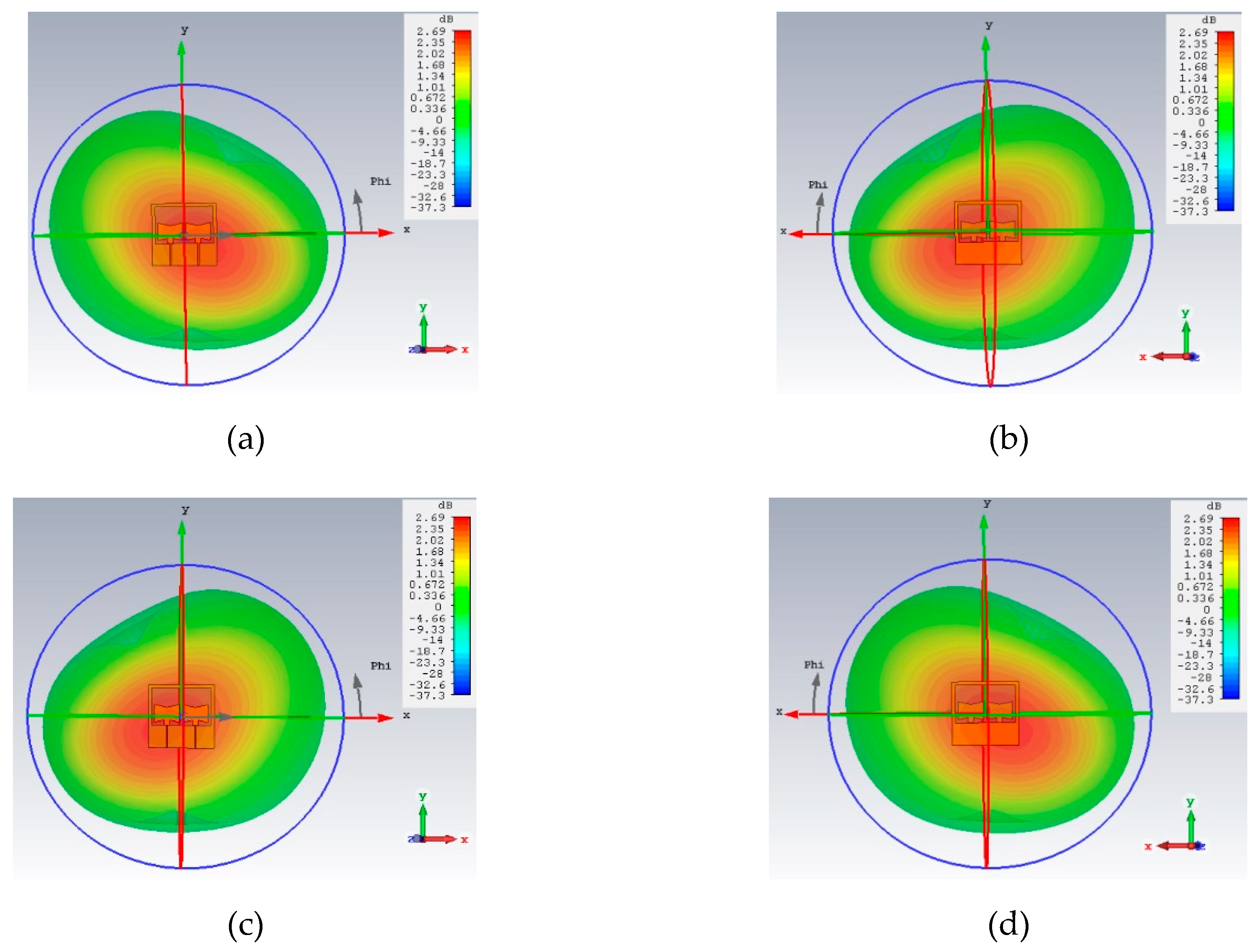
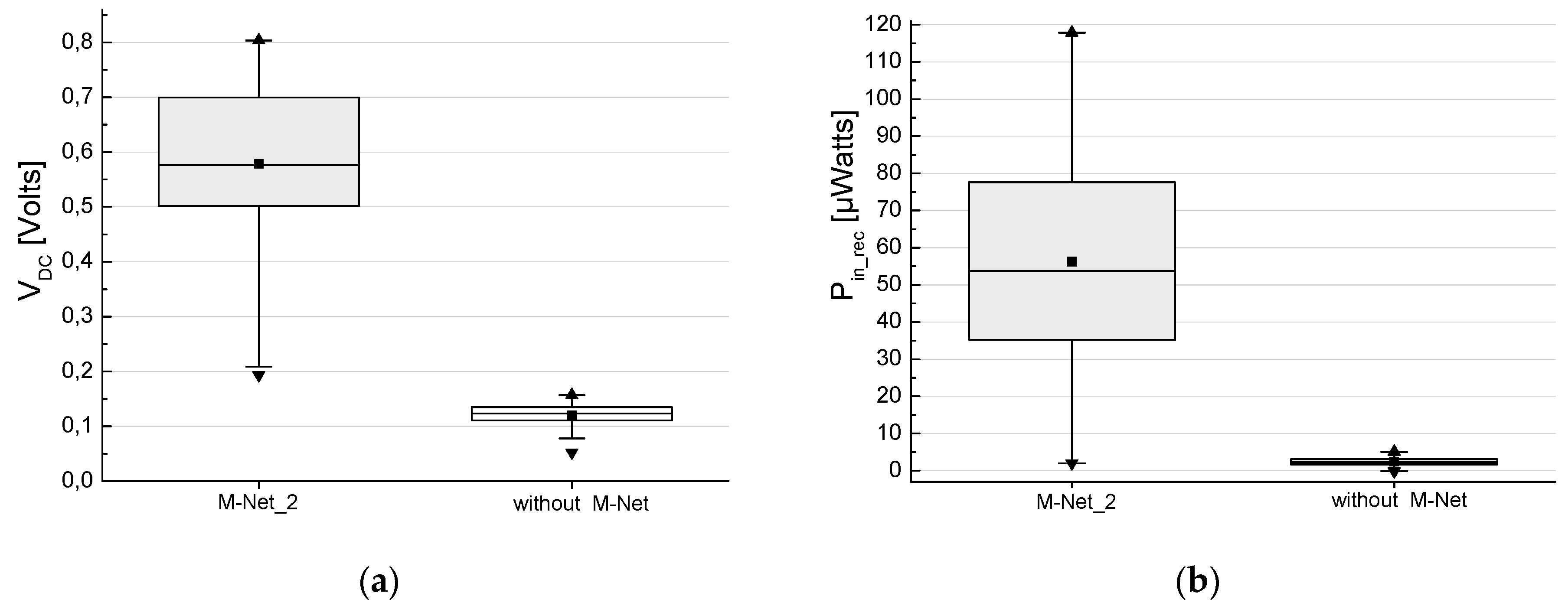
3.4. Results with M-Net_2
4. Conclusions
Author Contributions
Acknowledgments
Conflicts of Interest
References
- Tan, Z.; Qu, H.; Zhao, J.; Ren, G.; Wang, W. Self-Sustainable Dense Cellular M2m System with Hybrid Energy Harvesting and High Sensitivity Rectenna. IEEE Access 2019, 7, 19447–19460. [Google Scholar] [CrossRef]
- Ramesh, G.P.; Rajan, A. Microstrip Antenna Designs for RF Energy Harvesting. In Proceedings of the International Conference on Communication and Signal Processing (ICCSP 2014), Melmaruvathur, India, 3–5 April 2014; pp. 1653–1657. [Google Scholar]
- Sun, H.; Guo, Y.-X.; He, M.; Zhong, Z. Design of a high-efficiency 2.45-GHz rectenna for low-input-power energy harvesting. IEEE Antennas Wirel. Propag. Lett. 2012, 11, 929–932. [Google Scholar]
- Olgun, U.; Chen, C.-C.; Volakis, J.L. Investigation of rectenna array configurations for enhanced RF power harvesting. IEEE Antennas Wirel. Propag. Lett. 2011, 10, 262–265. [Google Scholar] [CrossRef]
- Niotaki, K.; Kim, S.; Jeong, S.; Collado, A.; Georgiadis, A.; Tenzeris, M.M. A compact dual-band rectenna using slot-loaded dual band folded dipole antenna. IEEE Antennas Wirel. Propag. Lett. 2012, 12, 1634–1637. [Google Scholar] [CrossRef]
- Palazzi, V.; Hester, J.; Bito, J.; Alimenti, F.; Kalialakis, C.; Collado, A.; Mezzanotte, P.; Georgiadis, A.; Roselli, L.; Tentzeris, M.M. A novel ultra-lightweight multiband rectenna on paper for RF energy harvestinG in the next generation LTE bands. IEEE Trans. Microw. Theory Tech. 2018, 66, 366–379. [Google Scholar] [CrossRef]
- Mansour, M.M.; Kanaya, H. Novel L-Slot matching circuit integrated with circularly polarized rectenna for wireless energy harvesting. Electronics 2019, 8, 651. [Google Scholar] [CrossRef]
- Yasuda, K.; Nishiyama, E.; Toyoda, I. A high efficiency differential rectenna employing two-parasitic-element stacked antenna. In Proceedings of the 2018 Asia-Pacific Microwave Conference (APMC-2018), Kyoto, Japan, 6–9 November 2018. WE2-C-4. [Google Scholar]
- Shen, S.; Chiu, C.; Murch, R.D. A Dual-Port Triple-Band L-Probe Microstrip Patch Rectenna for Ambient RF Energy Harvesting. IEEE Antennas Wirel. Propag. Lett. 2018, 16, 3071–3074. [Google Scholar] [CrossRef]
- Fantuzzi, M.; Masotti, D.; Costanzo, A. Rectenna array with RF-Uncoupled Closely-spaced Monopoles for Autonomous Localization. In Proceedings of the 48th European Microwave Conference (EuMA-2018), Madrid, Spain, 25–27 September 2018; pp. 765–768. [Google Scholar]
- Kishimoto, H.; Itoh, K.; Noguchi, K.; Ida, J. Wideband rectenna with inductive high-impedance folded dipole antenna. In Proceedings of the IEEE Wireless Power Transfer Conference (WPTC-2018), Montreal, QC, Canada, 3–7 June 2018. [Google Scholar]
- Okba, A.; Takacs, A.; Aubert, H. Compact rectennas for ultra-low-power wireless transmission applications. IEEE Trans. Microw. Theory Tech. 2019, 67, 1697–1707. [Google Scholar] [CrossRef]
- Lu, P.; Huang, K.M.; Yang, Y.; Cheng, F.; Wu, L. Frequency-reconfigurable rectenna with an adaptive matching stub for microwave power transmission. IEEE Antennas Wirel. Propag. Lett. 2019, 18, 956–960. [Google Scholar] [CrossRef]
- Polaiah, G.; Krishnamoorthy, K.; Kulkarni, M. Design of quatrefoil shape antennas for GSM1800 MHz and UMTS 2.1 GHz rectenna applications. In Proceedings of the URSI AP-RASC 2019, New Delhi, India, 9–15 March 2019. [Google Scholar]
- Chen, Y.-S.; You, J.-W. A scalable and multidirectional rectenna system for RF energy harvesting. IEEE Trans. Compon. Packag. Manuf. Technol. 2018, 8, 2060–2072. [Google Scholar] [CrossRef]
- Hu, Y.-Y.; Sun, S.; Xu, H.; Sun, H. Grid-array rectenna with wide angle coverage for effectively harvesting RF energy of low power density. IEEE Trans. Microw. Theory Tech. 2019, 67, 402–413. [Google Scholar] [CrossRef]
- Li, X.; Yang, L.; Huang, L. Novel Design of 2.45-GHz Rectenna Element and Array for Wireless Power Transmission. IEEE Access 2019, 7, 28356–28362. [Google Scholar] [CrossRef]
- Shen, S.; Chiu, C.; Murch, R.D. Multiport Pixel Rectenna for Ambient RF Energy Harvesting. IEEE Trans. Antennas Propag. 2018, 66, 644–656. [Google Scholar] [CrossRef]
- Karampatea, A.; Siakavara, K. Analysis and synthesis of double negative dielectric media rectenna systems for ambient microwave energy harvesting. Int. J. Antennas Propag. 2018, 2018, 2472738. [Google Scholar] [CrossRef]
- Karampatea, A.; Siakavara, K. Hybrid rectennas of printed dipole type on double negative dielectric media for powering sensors via RF ambient energy harvesting. Int. J. Electron. Commun. 2019, 108, 242–250. [Google Scholar] [CrossRef]
- Cheng, Y.; Sheng, B. A printed bowtie dipole broadband directional antenna. In Proceedings of the 6th Asia-Pacific Conference on Antennas and Propagation (APCAP-2017), Xi’an, China, 16–19 October 2017. [Google Scholar]
- Raut, S.; Petosa, A. A compact printed Bowtie antenna for ultra-wideband applications. In Proceedings of the 39th European Microwave Conference (EuMC-2009), Rome, Italy, 29 September–1 October 2009; pp. 81–84. [Google Scholar]
- Basta, N.P.; Falkenstein, E.A.; Popovic, Z. Bow-Tie Rectenna Arrays. Proceeedings of the IEEE Wireless Power Transfer Conference (WPTC-2015), Boulder, CO, USA, 13–15 May 2015. [Google Scholar]
- Kim, S.; Vyas, R.; Bito, J.; Niotaki, K.; Collado, A.; Georgiadis, A.; Tentzeris, M.M. Ambient RF energy-harvesting technologies for self-sustainable standalone wireless sensor platforms. Proc. IEEE 2014, 102, 1649–1666. [Google Scholar] [CrossRef]
- Durgun, A.C.; Balanis, C.A.; Birtcher, C.R.; Alle, D.R. Design, simulation, fabrication and testing of flexible bow-tie antennas. IEEE Trans. Antennas Propag. 2011, 59, 4425–4434. [Google Scholar] [CrossRef]
- Avago Technologies, Data Sheet HSMS-285x. Available online: https://pdf1.alldatasheet.com/datasheet-pdf/view/1072262/AVAGO/HSMS-285X.html (accessed on 23 January 2019).
- Song, C.; Huang, Y.; Zhou, J.; Carter, P.; Yuan, S.; Xu, Q.; Fei, Z. Matching network elimination in broadband rectennas for high efficiency wireless power transfer and energy harvesting. IEEE Trans. Ind. Electron. 2017, 64, 1950–1961. [Google Scholar] [CrossRef]
- Pozar, D.M. Microwave Engineering, 4th ed.; John Wiley & Sons: Hoboken, NJ, USA, 2012. [Google Scholar]
- Balanis, C.A. Antenna Theory: Analysis and Design, 4th ed.; John Wiley & Sons: Hoboken, NJ, USA, 2016. [Google Scholar]
- AVX-Advanced Electronic Components. Available online: https://www.avx.com (accessed on 23 January 2019).
- Johanson Technology. Available online: https://www.johansontechnology.com (accessed on 23 January 2019).


| L | H | a | b | d | g | w | s |
|---|---|---|---|---|---|---|---|
| 132 | 138.6 | 53.25 | 38.95 | 10.67 | 50.40 | 3 | 6.60 |
| L | H | G | D | s | d | g | c | w | e |
|---|---|---|---|---|---|---|---|---|---|
| 138.60 | 138.60 | 49.50 | 53.20 | 6.78 | 38.95 | 18.71 | 12 | 3 | 7 |
| M-Net_1 | M-Net_2 | ||
|---|---|---|---|
| L1 | 22 nH | C1 | 8.2 pF |
| L2 | 10 nH | C2 | 3.3 pF |
| L3 | 18 nH | L | 39 nF |
| C | 1 pF |
© 2019 by the authors. Licensee MDPI, Basel, Switzerland. This article is an open access article distributed under the terms and conditions of the Creative Commons Attribution (CC BY) license (http://creativecommons.org/licenses/by/4.0/).
Share and Cite
Karampatea, A.; Siakavara, K. Synthesis of Rectenna for Powering Micro-Watt Sensors by Harvesting Ambient RF Signals’ Power. Electronics 2019, 8, 1108. https://doi.org/10.3390/electronics8101108
Karampatea A, Siakavara K. Synthesis of Rectenna for Powering Micro-Watt Sensors by Harvesting Ambient RF Signals’ Power. Electronics. 2019; 8(10):1108. https://doi.org/10.3390/electronics8101108
Chicago/Turabian StyleKarampatea, Apostolia, and Katherine Siakavara. 2019. "Synthesis of Rectenna for Powering Micro-Watt Sensors by Harvesting Ambient RF Signals’ Power" Electronics 8, no. 10: 1108. https://doi.org/10.3390/electronics8101108
APA StyleKarampatea, A., & Siakavara, K. (2019). Synthesis of Rectenna for Powering Micro-Watt Sensors by Harvesting Ambient RF Signals’ Power. Electronics, 8(10), 1108. https://doi.org/10.3390/electronics8101108