High-Performance Multiple-Input Multiple-Output Antenna System For 5G Mobile Terminals

 ,
,  ,
,  , ,
, ,
Abstract
:1. Introduction
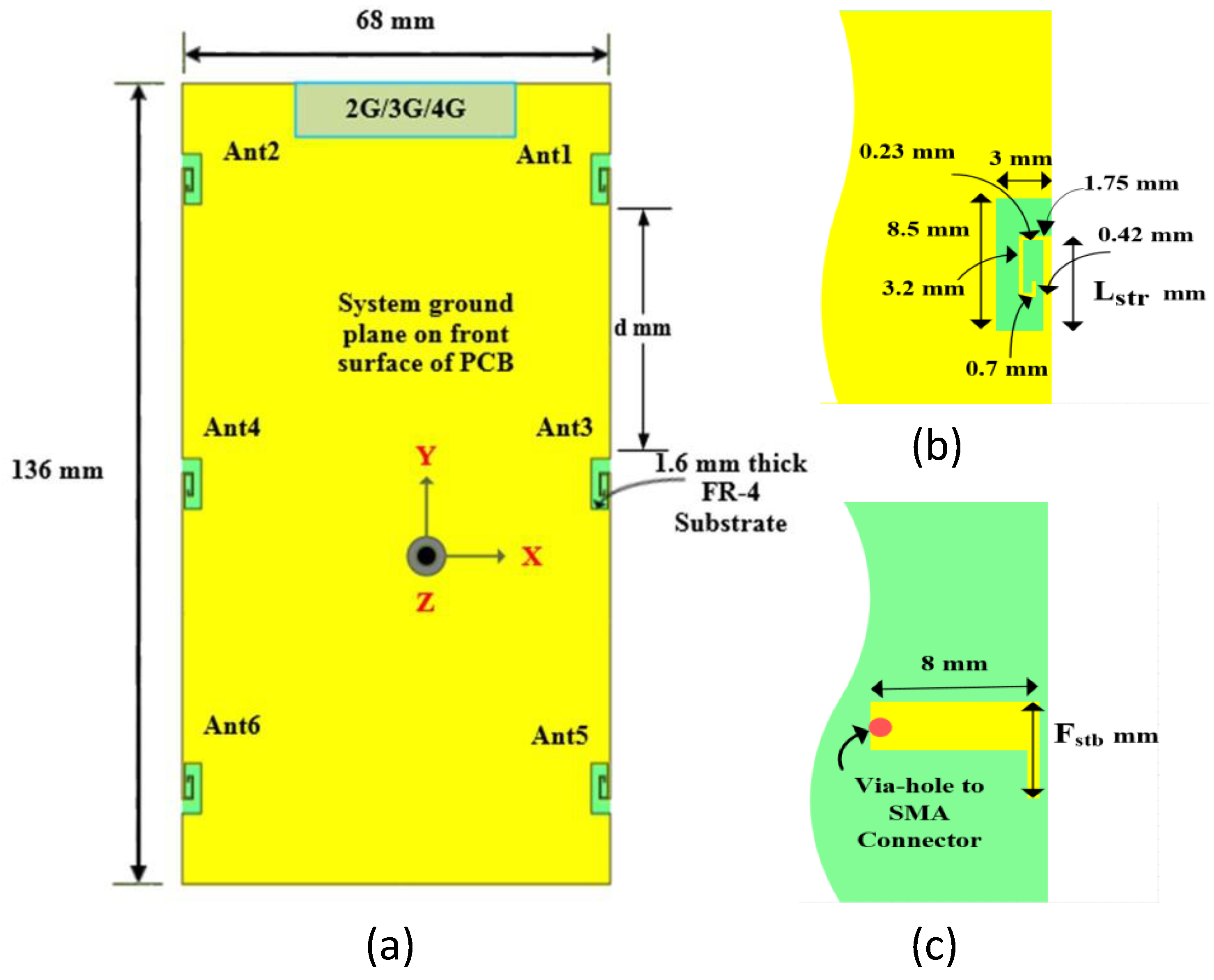
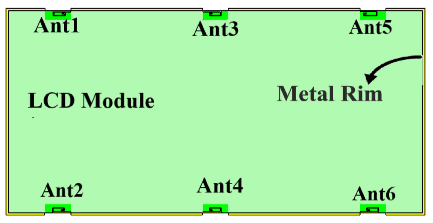
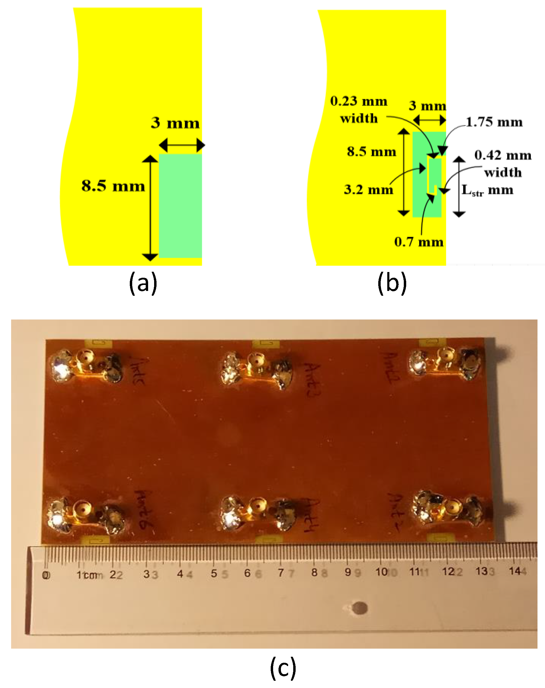
2. Antenna Geometry
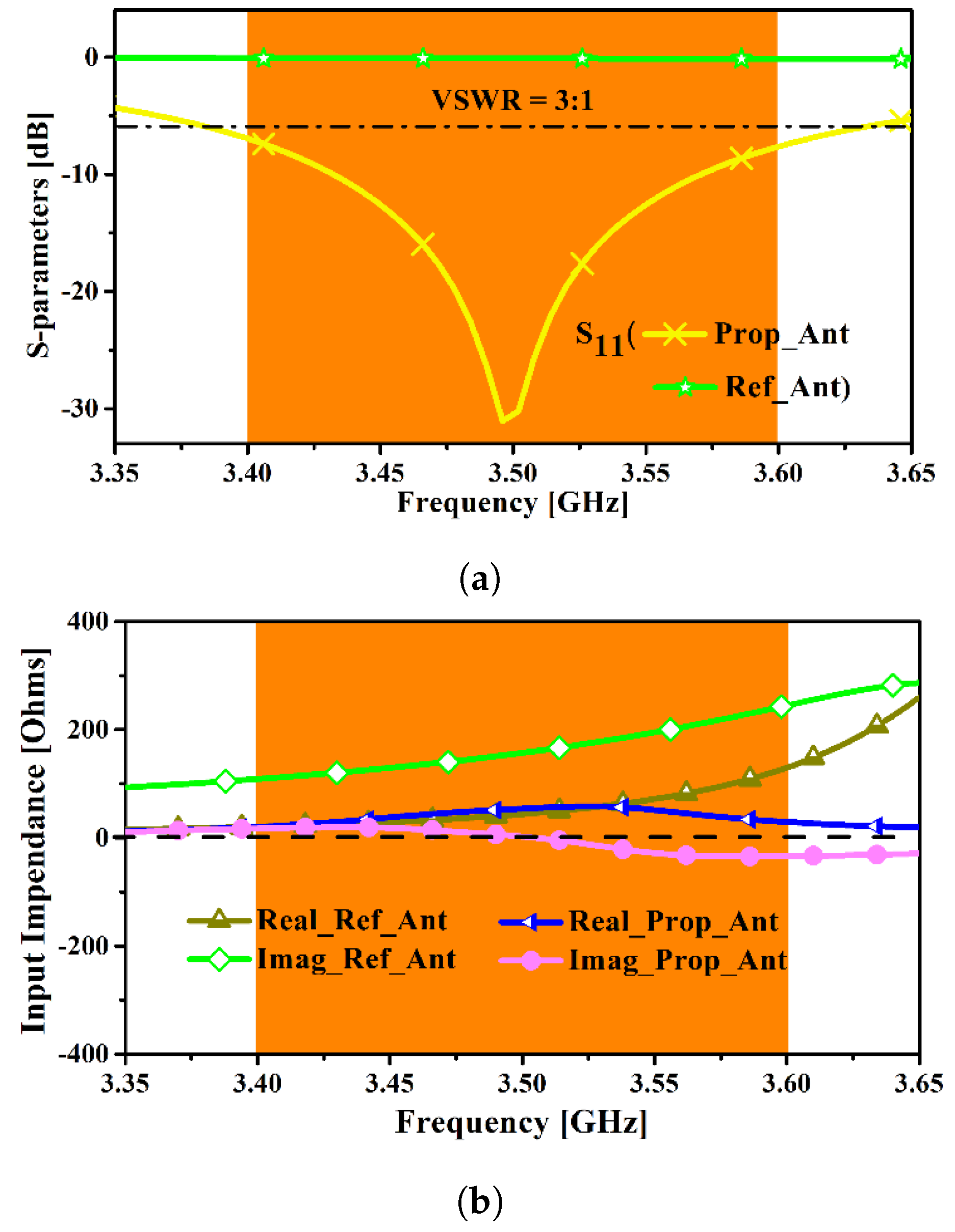
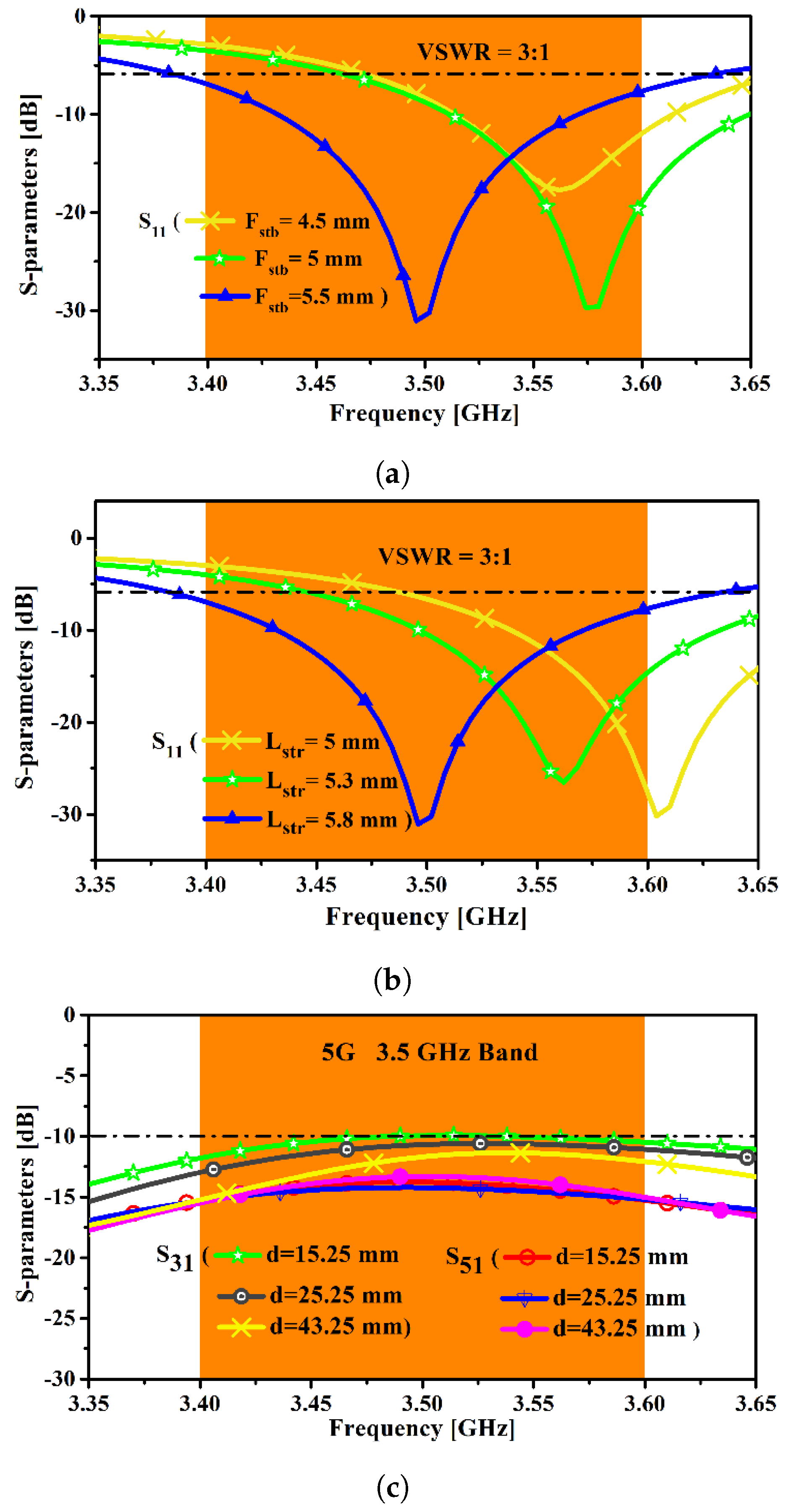
3. Results and Discussions
4. Measured Results
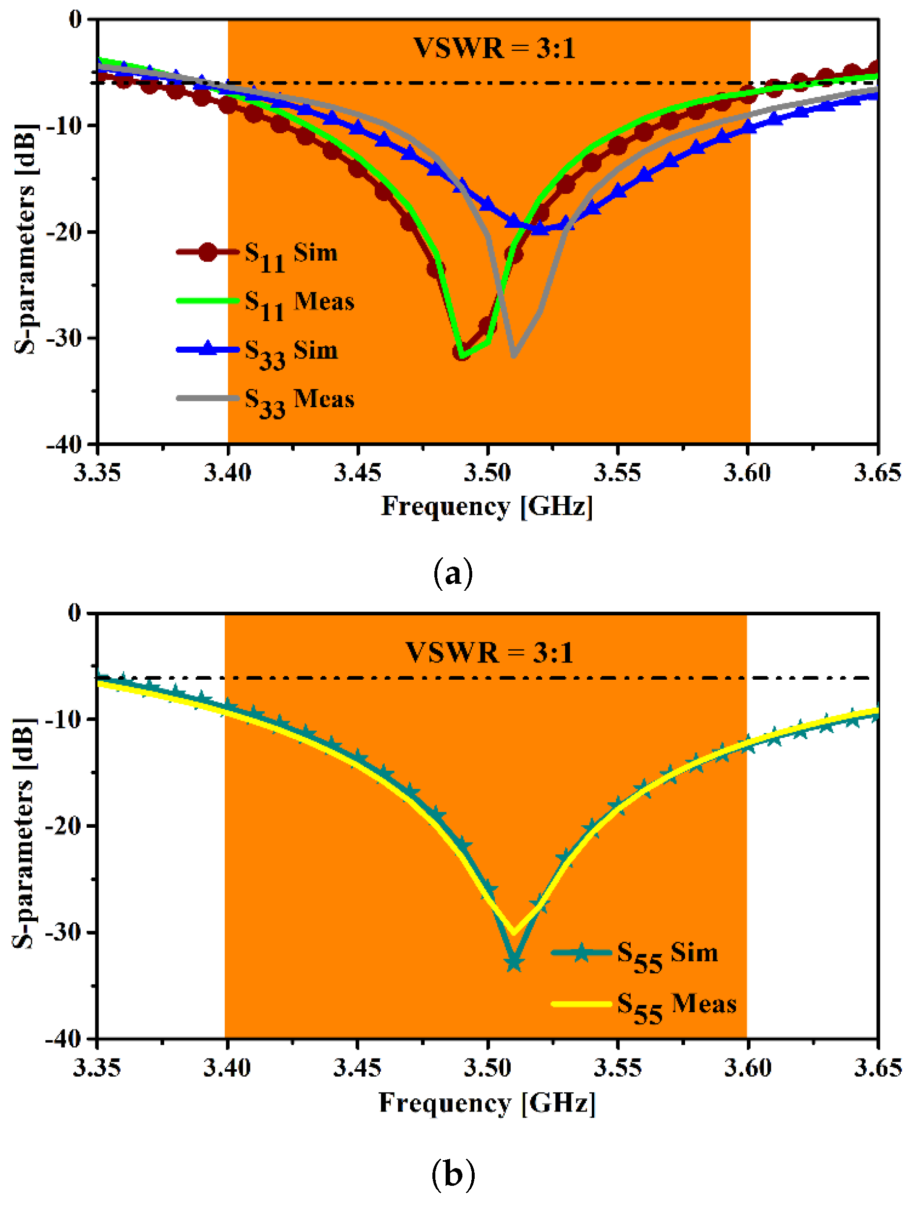
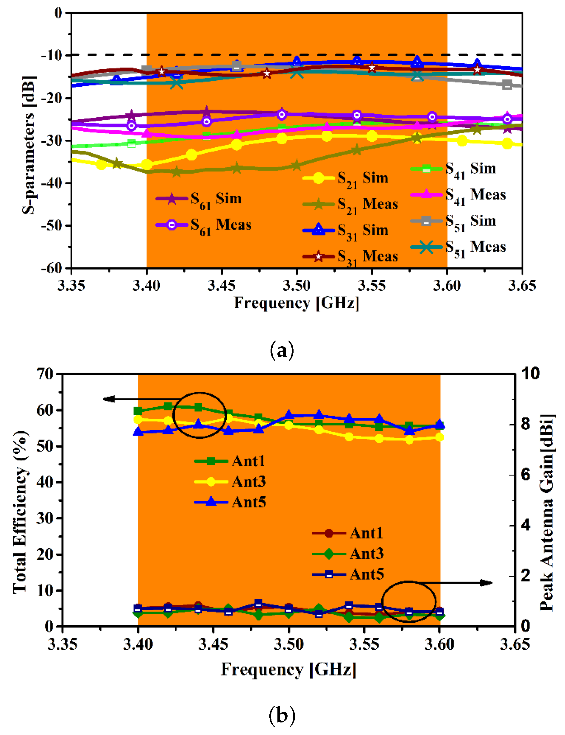
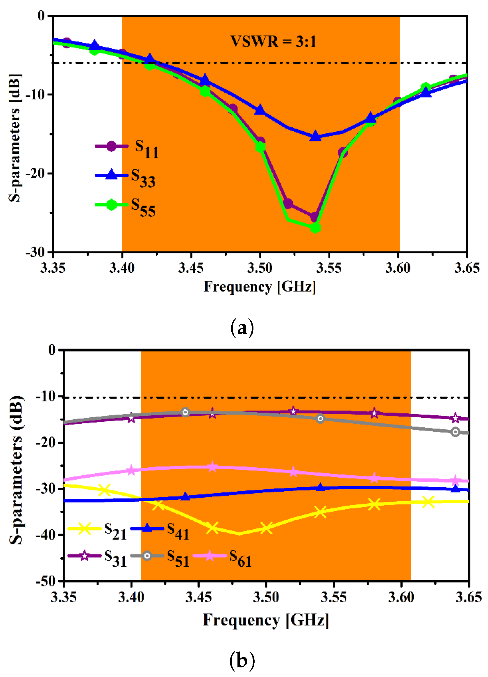
4.1. S-Parameters
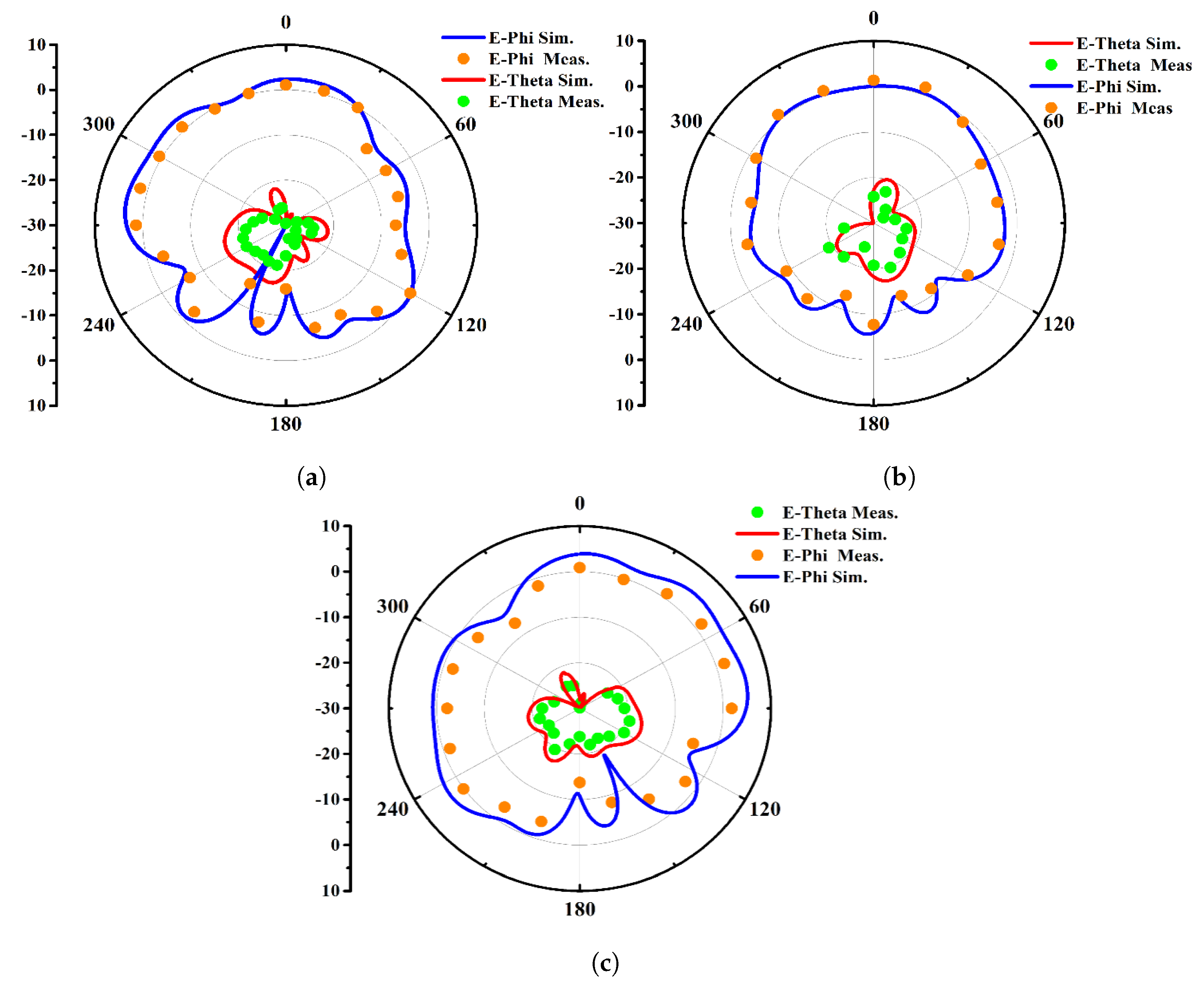
4.2. Radiation Pattern
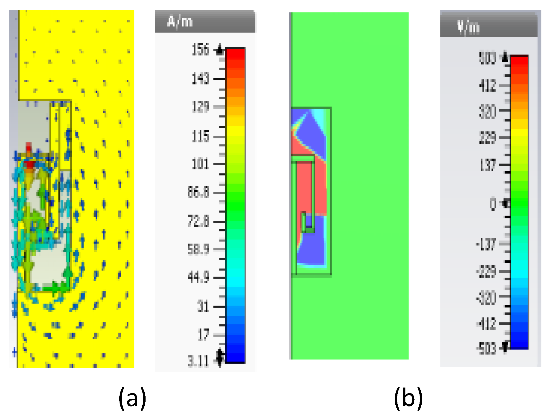
4.3. Surface Current and Electric Field Distribution
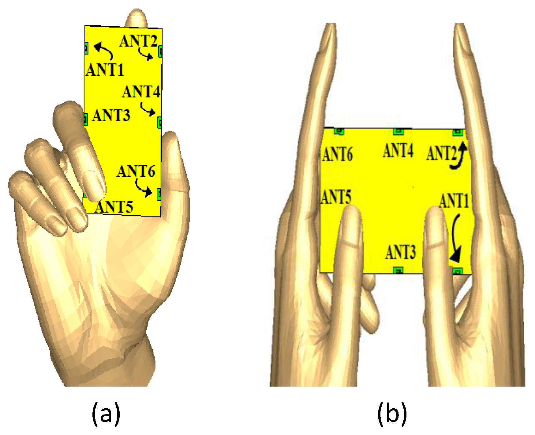
4.4. Customer’s Hand Effect
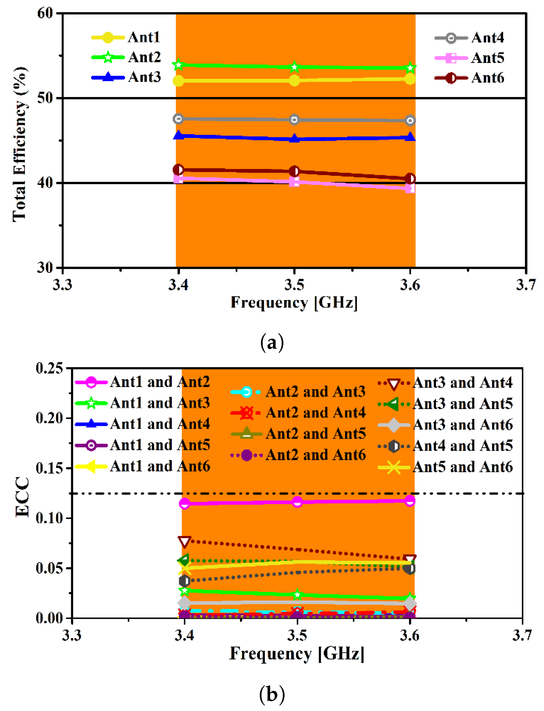
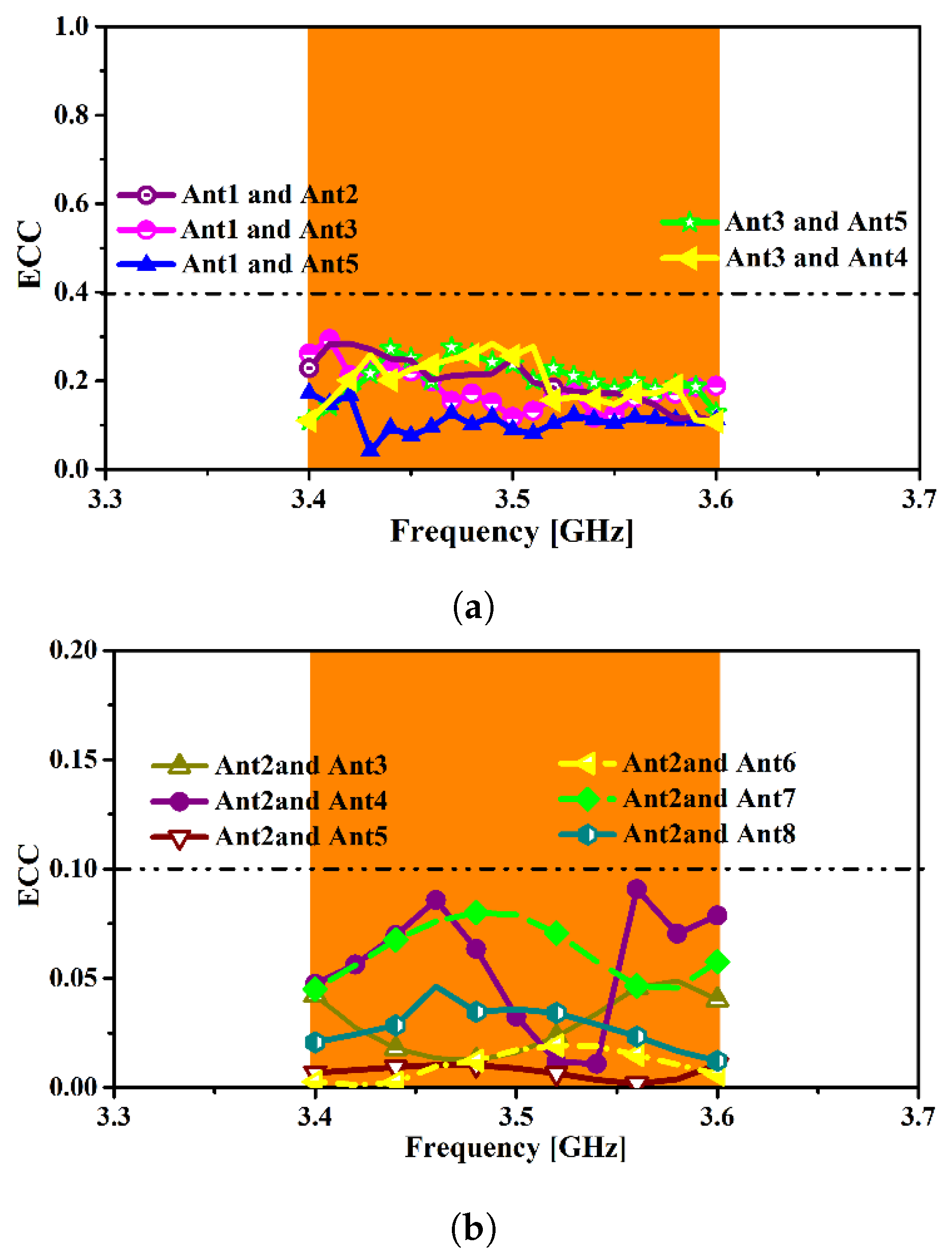
4.5. Key Performance Metrics Evaluation for MIMO Systems
4.6. Impact of Display Module (Metal Casing and Liquid Crystal Display)
5. Conclusions
Author Contributions
Funding
Conflicts of Interest
References
- Iqbal, A.; Smida, A.; Mallat, N.K.; Ghayoula, R.; Elfergani, I.; Rodriguez, J.; Kim, S. Frequency and pattern reconfigurable antenna for emerging wireless communication systems. Electronics 2019, 8, 407. [Google Scholar] [CrossRef]
- Werner, K.; Furuskog, J.; Riback, M.; Hagerman, B. Antenna configurations for 4x4 MIMO in LTE-field measurements. In Proceedings of the 2010 IEEE 71st Vehicular Technology Conference, Taipei, Taiwan, 16–19 May 2010; pp. 1–5. [Google Scholar]
- Wang, Y.; Du, Z. A wideband printed dual-antenna system with a novel neutralization line for mobile terminals. IEEE Antennas Wirel. Propag. Lett. 2013, 12, 1428–1431. [Google Scholar] [CrossRef]
- Shoaib, S.; Shoaib, I.; Shoaib, N.; Chen, X.; Parini, C.G. MIMO antennas for mobile handsets. IEEE Antennas Wirel. Propag. Lett. 2014, 14, 799–802. [Google Scholar] [CrossRef]
- Guo, J.; Fan, J.; Sun, L.; Sun, B. A four-antenna system with high isolation for mobile phones. IEEE Antennas Wirel. Propag. Lett. 2013, 12, 979–982. [Google Scholar] [CrossRef]
- Ikram, M.; Hussain, R.; Sharawi, M.S. Low profile 6-element modified-monopole MIMO antenna system for mobile applications. In Proceedings of the 2016 IEEE International Symposium on Antennas and Propagation (APSURSI), Fajardo, Puerto Rico, 26 June–1 July 2016; pp. 73–74. [Google Scholar]
- Chen, Z.; Geyi, W.; Zhang, M.; Wang, J. A study of antenna system for high order MIMO device. Int. J. Antennas Propag. 2016, 2016. [Google Scholar] [CrossRef]
- Sharawi, M.; Jan, M.; Aloi, D. Four-shaped 2 × 2 multi-standard compact multiple-input–multiple-output antenna system for long-term evolution mobile handsets. IET Microw. Antennas Propag. 2012, 6, 685–696. [Google Scholar] [CrossRef]
- Anguera, J.; Andújar, A.; Mateos, R.M.; Kahng, S. A 4 × 4 MIMO multiband antenna system with non-resonant elements for smartphone platforms. In Proceedings of the 2017 11th European Conference on Antennas and Propagation (EUCAP), Paris, France, 19–24 March 2017; pp. 2705–2708. [Google Scholar]
- Moradikordalivand, A.; Leow, C.Y.; Rahman, T.A.; Ebrahimi, S.; Chua, T.H. Wideband MIMO antenna system with dual polarization for WiFi and LTE applications. Int. J. Microw. Wirel. Technol. 2016, 8, 643–650. [Google Scholar] [CrossRef]
- Malathi, C.; Thiripurasundari, D. CSRR Loaded 2x1 Triangular MIMO Antenna for LTE Band Operation. Adv. Electromagn. 2017, 6, 78–83. [Google Scholar] [CrossRef]
- Yang, B.; Chen, M.; Li, L. Design of a four-element WLAN/LTE/UWB MIMO antenna using half-slot structure. AEU-Int. J. Electron. Commun. 2018, 93, 354–359. [Google Scholar] [CrossRef]
- Wong, K.L.; Chen, Y.C.; Li, W.Y. Four LTE low-band smartphone antennas and their MIMO performance with user’s hand presence. Microw. Opt. Technol. Lett. 2016, 58, 2046–2052. [Google Scholar] [CrossRef]
- Wong, K.L.; Kang, T.W.; Tu, M.F. Internal mobile phone antenna array for LTE/WWAN and LTE MIMO operations. Microw. Opt. Technol. Lett. 2011, 53, 1569–1573. [Google Scholar] [CrossRef]
- Wang, T.; Li, G.; Huang, B.; Miao, Q.; Fang, J.; Li, P.; Tan, H.; Li, W.; Ding, J.; Li, J.; et al. Spectrum analysis and regulations for 5G. In 5G Mobile Communications; Springer: Berlin/Heidelberg, Germany, 2017; pp. 27–50. [Google Scholar]
- Anguera, J.; Sanz, I.; Mumbrú, J.; Puente, C. Multiband handset antenna with a parallel excitation of PIFA and slot radiators. IEEE Trans. Antennas Propag. 2009, 58, 348–356. [Google Scholar] [CrossRef]
- Abedin, M.; Ali, M. Modifying the ground plane and its effect on planar inverted-F antennas (PIFAs) for mobile phone handsets. IEEE Antennas Wirel. Propag. Lett. 2003, 2, 226–229. [Google Scholar] [CrossRef]
- Anguera, J.; Cabedo, A.; Picher, C.; Sanz, I.; Ribó, M.; Puente, C. Multiband handset antennas by means of groundplane modification. In Proceedings of the 2007 IEEE Antennas and Propagation Society International Symposium, Honolulu, HI, USA, 9–15 June 2007; pp. 1253–1256. [Google Scholar]
- Hossa, R.; Byndas, A.; Bialkowski, M. Improvement of compact terminal antenna performance by incorporating open-end slots in ground plane. IEEE Microw. Wirel. Components Lett. 2004, 14, 283–285. [Google Scholar] [CrossRef]
- Chang, T.H.; Kiang, J.F. Compact multi-band H-shaped slot antenna. IEEE Trans. Antennas Propag. 2013, 61, 4345–4349. [Google Scholar] [CrossRef]
- Gabriel, C. Tissue equivalent material for hand phantoms. Phys. Med. Biol. 2007, 52, 4205. [Google Scholar] [CrossRef] [PubMed]
- Certification, C. Test Plan for mobile station over the air performance. Method Meas. Radiat. Power Receiv. Perform. Revis. 2005, 2, 273–275. [Google Scholar]
- Pelosi, M.; Franek, O.; Knudsen, M.; Pedersen, G. Influence of dielectric loading on PIFA antennas in close proximity to user’s body. Electron. Lett. 2009, 45, 246–248. [Google Scholar] [CrossRef]
- Plicanic, V.; Lau, B.K.; Ying, Z. Performance of a multiband diversity antenna with hand effects. In Proceedings of the 2008 International Workshop on Antenna Technology: Small Antennas and Novel Metamaterials, Chiba, Japan, 4–6 March 2008; pp. 534–537. [Google Scholar]
- Bouazizi, A.; Zaibi, G.; Iqbal, A.; Basir, A.; Samet, M.; Kachouri, A. A dual-band case-printed planar inverted-F antenna design with independent resonance control for wearable short range telemetric systems. Int. J. Microw. Comput. Eng. 2019, 29, e21781. [Google Scholar] [CrossRef]
- Ilvonen, J.; Valkonen, R.; Holopainen, J.; Kivekäs, O.; Vainikainen, P. Reducing the interaction between user and mobile terminal antenna based on antenna shielding. In Proceedings of the 2012 6th European Conference on Antennas and Propagation (EUCAP), Prague, Czech Republic, 26–30 March 2012; pp. 1889–1893. [Google Scholar]
- Zhang, S.; Zhao, K.; Ying, Z.; He, S. Adaptive quad-element multi-wideband antenna array for user-effective LTE MIMO mobile terminals. IEEE Trans. Antennas Propag. 2013, 61, 4275–4283. [Google Scholar] [CrossRef]
- Ding, Y.; Du, Z.; Gong, K.; Feng, Z. A novel dual-band printed diversity antenna for mobile terminals. IEEE Trans. Antennas Propag. 2007, 55, 2088–2096. [Google Scholar] [CrossRef]
- Iqbal, A.; Saraereh, O.A.; Ahmad, A.W.; Bashir, S. Mutual coupling reduction using F-shaped stubs in UWB-MIMO antenna. IEEE Access 2017, 6, 2755–2759. [Google Scholar] [CrossRef]
- Iqbal, A.; A Saraereh, O.; Bouazizi, A.; Basir, A. Metamaterial-based highly isolated MIMO antenna for portable wireless applications. Electronics 2018, 7, 267. [Google Scholar] [CrossRef]
- Iqbal, A.; Basir, A.; Smida, A.; Mallat, N.K.; Elfergani, I.; Rodriguez, J.; Kim, S. Electromagnetic Bandgap Backed Millimeter-Wave MIMO Antenna for Wearable Applications. IEEE Access 2019, 7, 111135–111144. [Google Scholar] [CrossRef]
- Ying, Z.; Bolin, T.; Plicanic, V.; Derneryd, A.; Kristensson, G. Diversity antenna terminal evaluation. In Proceedings of the 2005 IEEE Antennas and Propagation Society International Symposium, Washington, DC, USA, 3–8 July 2005; Volume 2, pp. 375–378. [Google Scholar]
- Tian, R.; Lau, B.K.; Ying, Z. Multiplexing efficiency of MIMO antennas. IEEE Antennas Wirel. Propag. Lett. 2011, 10, 183–186. [Google Scholar] [CrossRef]
- Kildal, P.S.; Rosengren, K. Correlation and capacity of MIMO systems and mutual coupling, radiation efficiency, and diversity gain of their antennas: Simulations and measurements in a reverberation chamber. IEEE Commun. Mag. 2004, 42, 104–112. [Google Scholar] [CrossRef]


| Frequency (GHz) | MEG Ant1 (dB) | MEG Ant2 (dB) | MEG Ant3 (dB) | MEG Ant4 (dB) | MEG Ant5 (dB) | MEG Ant6 (dB) |
|---|---|---|---|---|---|---|
| Indoor XPR = 1 | −3.20 | −3.15 | 3.20 | −3.18 | −3.22 | −3.13 |
| Indoor XPR = 5 | −3.40 | −3.50 | −3.64 | −3.48 | −3.50 | −3.70 |
| MIMO Configuration | Scenario | ECC | Channel Capacity (bps/Hz) |
|---|---|---|---|
| Free Space | 0.012 | 34.25 | |
| 6 × 6 | Single-Hand Mode | 0.10 | 27.43 |
| Two-Hand Mode | 0.07 | 23.24 |
| Ref. | Bandwidth (GHz) | #Ant | T.E% (meas) | PCC | ECC (Required < 0.5) |
|---|---|---|---|---|---|
| Proposed | 3.4–3.6 | 6 | 50 to 60 | 32 | 0.15 |
| [3] | 1.67–2.76 | 2 | 70 to 80 | Not Given | 0.05 |
| [4] | 1.7–2.2 | 4 | 83 to 89 | Not Given | 0.02 |
| [5] | 0.6-0.9/1.6–2.6 | 4 | 40 to 70 | Not Given | 0.25 |
| [7] | 1.8–1.9/2.3–2.6 | 6 | 37 to 79 | Not Given | 0.16 |
| [8] | 0.73–0.79/2.3–2.4 | 4 | ∼70 | Not Given | 0.4 |
| [13] | 0.6–0.9 | 4 | 40 to 50 | 17 | 0.3 |
© 2019 by the authors. Licensee MDPI, Basel, Switzerland. This article is an open access article distributed under the terms and conditions of the Creative Commons Attribution (CC BY) license (http://creativecommons.org/licenses/by/4.0/).
Share and Cite
Abdullah, M.; Kiani, S.H.; Abdulrazak, L.F.; Iqbal, A.; Bashir, M.A.; Khan, S.; Kim, S. High-Performance Multiple-Input Multiple-Output Antenna System For 5G Mobile Terminals. Electronics 2019, 8, 1090. https://doi.org/10.3390/electronics8101090
Abdullah M, Kiani SH, Abdulrazak LF, Iqbal A, Bashir MA, Khan S, Kim S. High-Performance Multiple-Input Multiple-Output Antenna System For 5G Mobile Terminals. Electronics. 2019; 8(10):1090. https://doi.org/10.3390/electronics8101090
Chicago/Turabian StyleAbdullah, Mujeeb, Saad Hassan Kiani, Lway Faisal Abdulrazak, Amjad Iqbal, M. A. Bashir, Shafiullah Khan, and Sunghwan Kim. 2019. "High-Performance Multiple-Input Multiple-Output Antenna System For 5G Mobile Terminals" Electronics 8, no. 10: 1090. https://doi.org/10.3390/electronics8101090
APA StyleAbdullah, M., Kiani, S. H., Abdulrazak, L. F., Iqbal, A., Bashir, M. A., Khan, S., & Kim, S. (2019). High-Performance Multiple-Input Multiple-Output Antenna System For 5G Mobile Terminals. Electronics, 8(10), 1090. https://doi.org/10.3390/electronics8101090