1. Introduction
Visible light communication (VLC) has recently become popular as an alternative to radio and infrared communication systems [
1,
2,
3]. Visible light has several features that distinguish it from radio frequencies, such as the availability of unique bandwidths that are not subject to interference from electromagnetic waves. At the same time, light-emitting diodes (LEDs) offer benefits over other light sources, such as high speed, small size, long lifetime, and rapid switching. By combining these two factors, it is possible to provide high-speed communication using VLC while maintaining the basic functionality (e.g., illumination, displays, etc.) of visible light.
Compared to radio frequency (RF) communication systems, VLC systems offer distinct channel characteristics and signal sources. Variable on-off keying (VOOK), variable pulse position modulation (VPPM), multiple PPM (MPPM), pulse dual slope modulation (PDSM), orthogonal frequency division multiplexing (OFDM), and subcarrier modulations are well-known modulation schemes of VLC systems [
4,
5,
6,
7,
8]. Note that intensity variation of the optical signal is the main key point of these modulation schemes. In wavelength division multiplexing (WDM), different wavelengths are used to multiplex various optical signals into a single optical fiber [
9]. WDM can be used in VLC systems by implementing it with LEDs of different wavelengths by varying the intensity of the signals to transmit information data. To receive the transmitted data, a photodiode (PD) along with different band-pass filters are used. Finally, the transmitted data is recovered by demodulating the received signal on PD.
Color-shift keying (CSK), the first color space-based modulation scheme, was proposed by the IEEE 802.15.7 Task Group [
10,
11]. However, CSK is not suitable for communication under target color variation and, in which case, CSK may exhibit lower performance than traditional intensity-based WDM [
10]. The target color indicates the desired color for LED lighting. In a past paper [
12], constellation designs for CSK were examined using billiard algorithms, however, any analytical verification could not be shown for the solution of constellation design for balancing color. In numerous instances of the literature [
13,
14,
15,
16], to overcome this limitation, generalized color modulation (GCM), one of the color-space-based modulation (CSBM) methods, was introduced and resolved for the color-independent VLC systems. The term “color-independent” implies the independence of light color and intensity variations. In this way, a VLC system can perform seamless communication that can preserve the originality and brightness of lighting color. In other words, GCM allows communication without compromising the original lighting color. As a result, any data stream can be delivered using GCM regardless of the target color. GCM also has a number of other advantageous features, such as dimming control, color independence, independence from the number of LEDs and PDs, and acceptable BER performance in the presence of color variation.
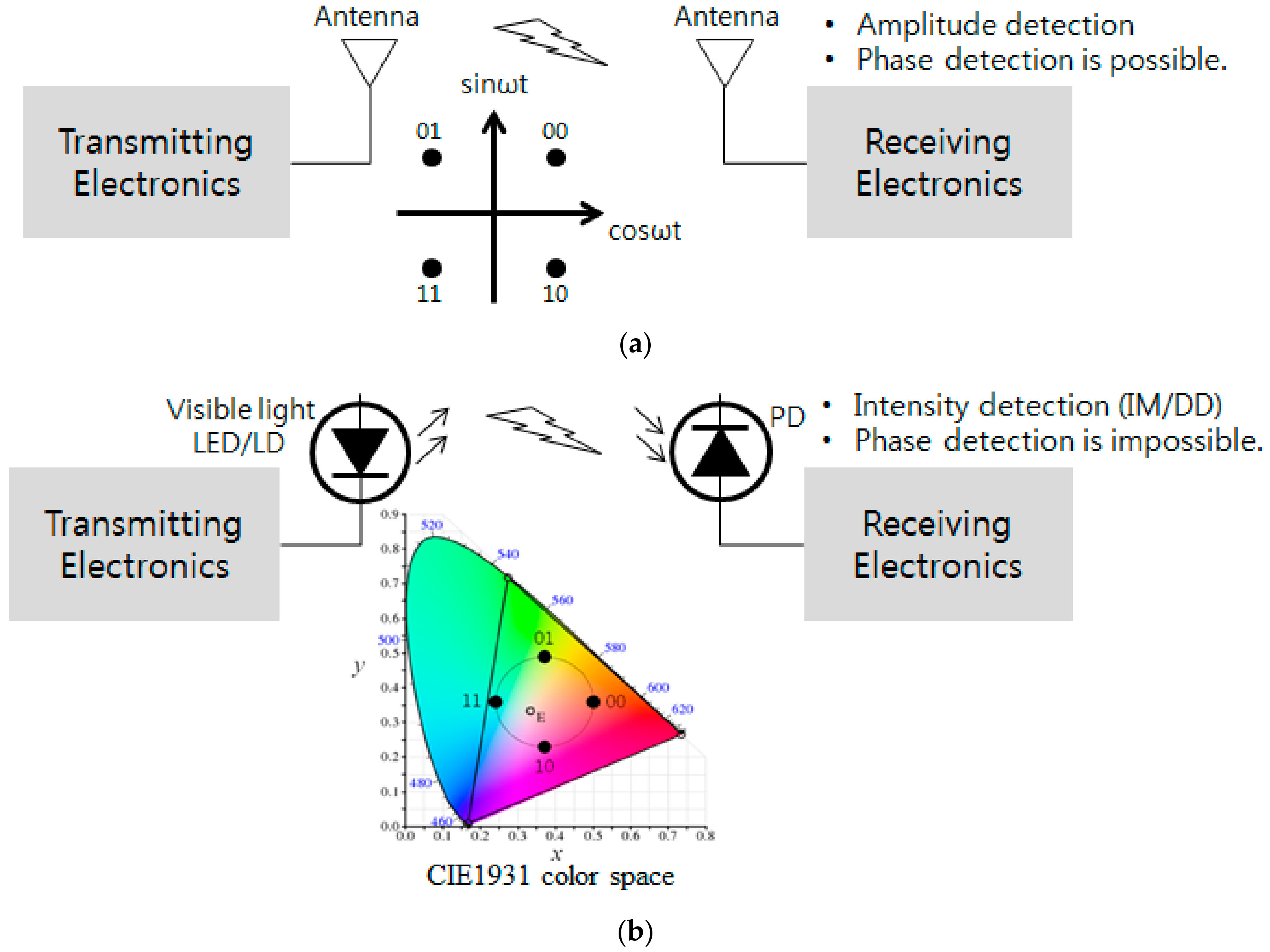
Figure 1 presents a simple conceptual block diagram of a color-space-based VLC system in comparison to a carrier-signal-based RF system.
However, previous studies in wireless optical communication using visible light with photodiode receivers have either been limited to short distances or have required complicated processing at the receiver. Photodiodes can convert pulses at a fairly high rate but suffer from significant interference and background light noise. As a result, the signal-to-noise ratio (SNR) is very low and the communication range shortened. It is possible to overcome this data transmission rate limitation and thus realize a larger transmission range by employing a camera as a receiver and a light emitting array as a transmitter, based on visual multiple input multiple output (MIMO) [
17,
18].
2. Light Color Spaces
Colors can be represented by various forms of color space, such as CIE1931 (CIEXYZ), CIE1976 (CIELUV), RGB, HSV, HSL, CMY, YUV (PAL), and YIQ (NTSC) [
19]. In the color space, sources (e.g., LEDs) and receiver (e.g., PDs) can be denoted as points. The minimum geometric area of a color space that contains all LED points is defined as the gamut area. Inside this area, any color can be created by combining the colors from the LEDs. The following two types of color space are particularly useful for the system proposed in this paper.
2.1. Color Space CIE1931
We consider the CIE1931 color space because of its simplicity. The tristimulus values (
,
, and
) represent the three primary color quantities of the three-component additive color model needed to produce a target color [
19].
In (1),
indicates the wavelength (nanometers) of the monochromatic light for each corresponding primary color.
,
, and
are the three color matching functions for the CIE1931 color space, and
is the spectral power distribution of a light source. The three normalized tristimulus values can be determined by
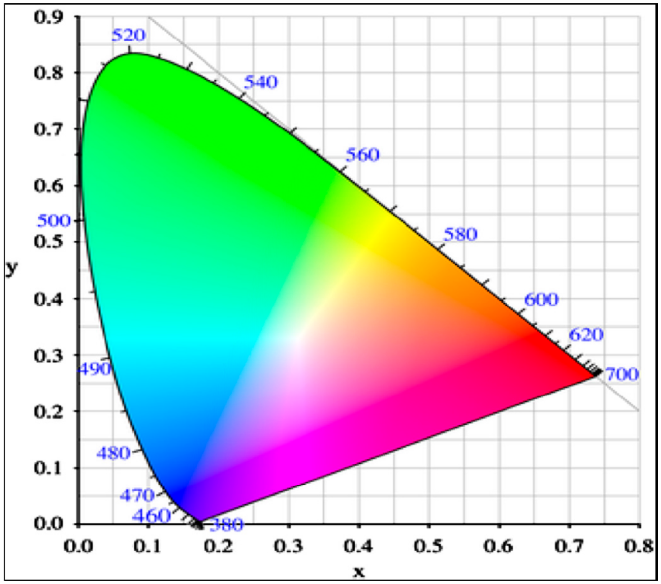
Using these normalized values, a CIE1931 color space chromaticity diagram can be produced [
19]. The
-plane of a chromaticity diagram is shown in
Figure 2. The CIE1931 chromaticity diagram is not perceptually uniform since it is derived from the human-eye response function.
To determine the color triple (
from the (
,
) coordinates of the CIE1931 color space, information for
(luminance) must be known. We can calculate the tristimulus values using (2) and (3) [
19].
The (
,
) coordinates represent the colors in the CIE1931 color space. The colors can also be represented by the proportion of
,
, and
in the RGB color space; the wavelength of a monochromatic light source in these three channels is 700 nm, 546 nm, and 436 nm, respectively. The
and
coordinate systems have a linear relationship with each other, thus one can be transformed into the other [
19].
2.2. Color Space CIE L*u*v* (CIELUV)
A detailed description of the CIELUV color space is included in a past paper [
19]. The key advantage of this color space is that the distance between two points is approximately proportional to the perceived color difference. The color resulting from the addition of two different colors will fall on a connecting line. CIELUV has better uniformity for perceived colors than does CIE1931. Therefore, our proposed modulation schemes [
13,
14] are based on the CIELUV color space in order to have perceptual uniformity that is close to that of the human eye in the transmitter (LEDs) and receiver (PDs).
3. Generalized Color Modulation
GCM was introduced to make the VLC system color-independent [
13,
14]. Using this scheme, it is possible to send any data stream with multiple LEDs that are independent of the target color of the VLC system. Color independency is one of the most important advantages of GCM over other VLC modulation schemes. Because GCM can produce any target color within a gamut area by combining other colors, it is possible to establish accurate communication using a VLC system while maintaining the original color and brightness. The target color can also be demapped on the receiver side from the received color symbols without having information about the target color. Generally, in WDM, transmitter and receiver use a definite number of wavelengths. In contrast, in GCM, the number of wavelengths can be chosen within the visible band depending on the application. In other words, GCM is independent of the number of LEDs and PDs. In addition, a fixed total light intensity can be maintained over time, which allows dimming control and flicker-free operation, whereas other intensity-based modulations (e.g., OOK and PPM) alter the light intensity to send data.
To represent the target color, GCM uses a constellation diagram with 2
m points (m-bit data) in a color space, with each point in this diagram representing a transmitted data symbol. They are mapped onto RGB LEDs using (4) and (6). On the receiver side, PDs detect the RGB intensities, from which the (x, y) coordinates are determined using (5) and (2). Finally, the error boundary decision (EBD) and the Euclidean distance are used to demap the received points into the original data symbols [
15].
Because OFDM is known to be a useful modulation method for VLC systems for several reasons [
7,
20,
21], an OFDM-based VLC system that can be color independent using CSBM was presented previously [
22]. With all the promising advantages of OFDM, the proposed system can be applied to all colors in the visible band. In a past paper [
22], it demonstrated robustness of the proposed OFDM-VLC system to inter-symbol-interference (ISI) and a large peak-to-average power ratio (PAPR) while maintaining color independency.
In GCM, we define the data symbols using a constellation diagram in the color space. We generate the constellation based on two assumptions:
The transmitted data symbols are selected in such a way that they are random and equidistant from each other on the circumference of the constellation diagram.
The changing rates of the target color are lower than the data rates.
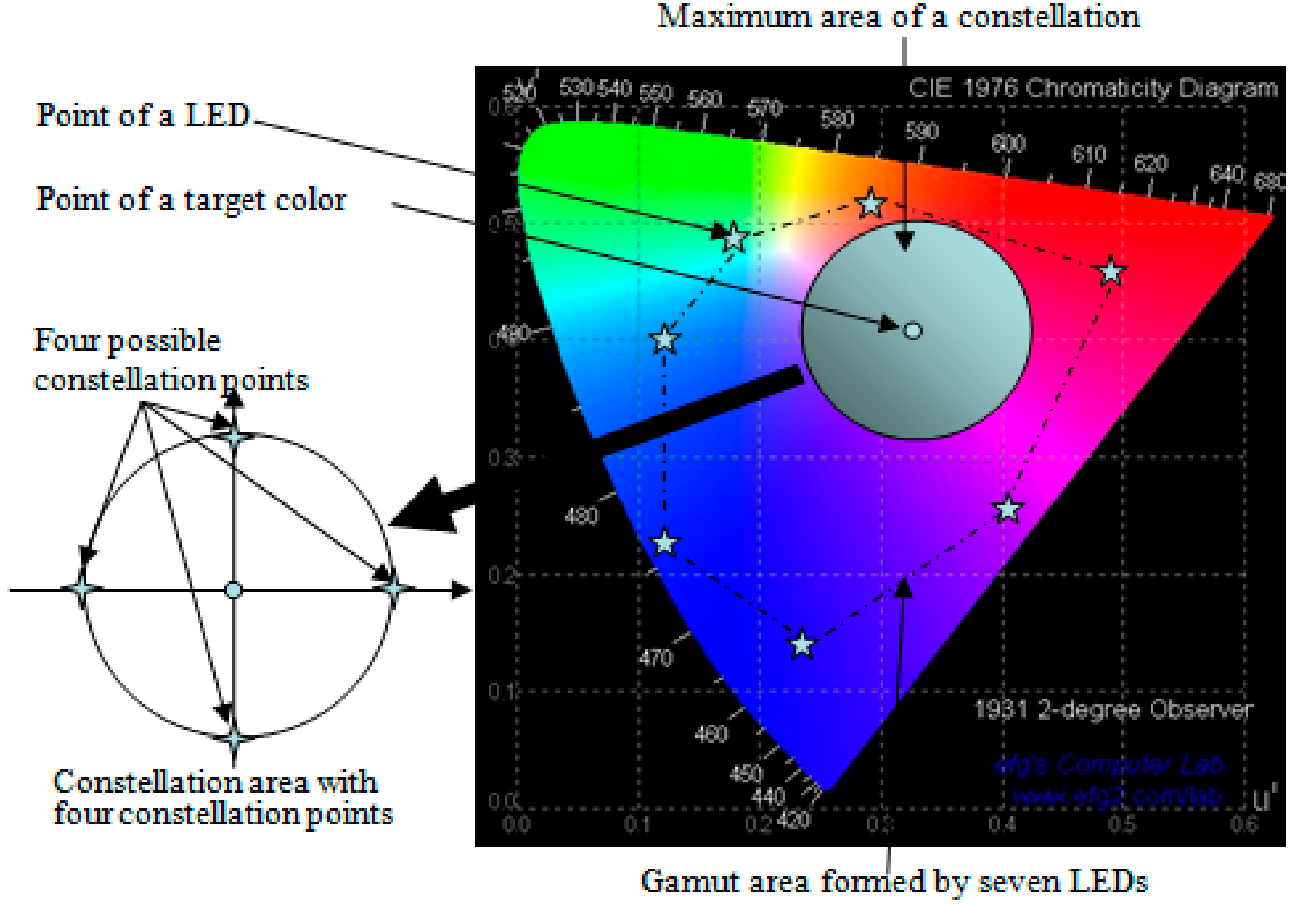
To generate the constellation diagram, we consider two aspects when determining the points in the light color space: (i) colors as symbols are used to determine a target color perceivable to the human eye and (ii) the maximum distance between two adjacent constellation points are preferred in the constellation diagram. In order to reduce the symbol error rate (SER), the first assumption is the best choice because it minimizes the effect of interference. Additionally, the area of the constellation diagram has to be maximized when the second aspect is considered.
The area of constellation diagram is maximized in two ways: (i) the coordinate of the target color becomes the center of constellation diagram and (ii) the coordinates of the LEDs are used to form the gamut area. Based on this, the maximum area of a constellation diagram is constructed by drawing the largest circle inside the gamut area in a manner so that the center of the largest circle represents the target color point.
Figure 3 represents the generation of a constellation diagram with a target color [
14]. In this case, the constellation points are arranged using a similar arrangement to that of RF circular quadrature amplitude modulation (QAM). More examples of circle-type and line-type constellation diagrams can be found in a past paper [
16]. We suppose that equiprobable symbol transmission is valid due to the compensation and interleaving algorithm. The target color can then be obtained from the averaged RGB value with a number of symbols as described in (7),
where
denotes the position of the target color,
denotes the position of the
symbol, and
is the number of symbols used to calculate the moving average. From the sense of probability, as
increases,
moves closer to the actual target color.
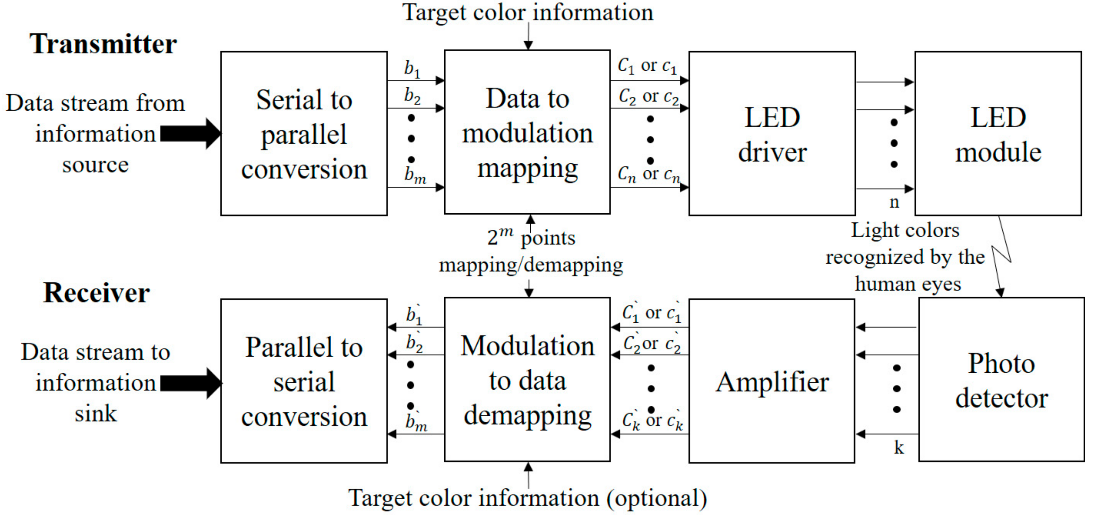
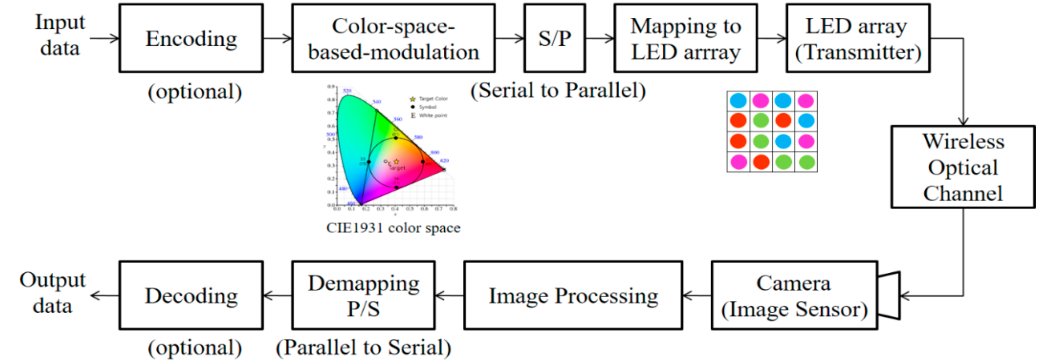
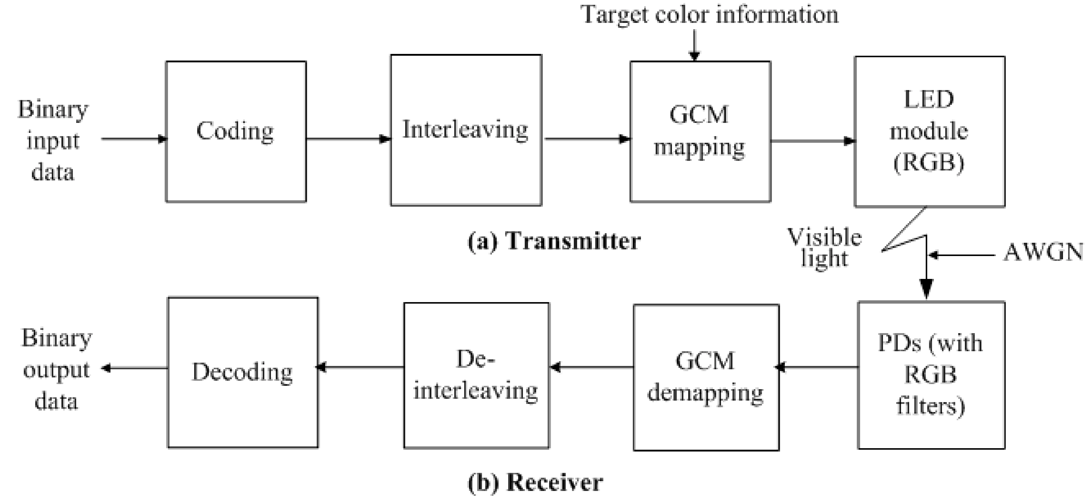
4. CSBM-Based VLC System Description
Figure 4 presents the total representation of a CSBM-based VLC system [
13,
16]. After converting the input from serial to parallel, we define the data symbols from the light color space using constellation points. A point can be mapped to the intensities of n LEDs at the transmitter. The average of every constellation point becomes the target color. The target color may be selected from the gamut area, and the information data can be transmitted using constellation points corresponding to the target color. Thus, the proposed system enables color-independent visible light communication. On the receiving side, the target color information is optional because it can be generated from the average of received data symbols [
14]. After that, intensities at the PDs are amplified. Finally, after the demapping operation, m-bit output is converted into a serial data stream.
A detailed explanation of mapping and demapping can be found in the literature [
13,
16].
Additive white Gaussian noise (AWGN) is assumed as channel noise. Typically, it is caused by background lighting that can interfere with the VLC signal. Optical filters can be useful for minimizing the noise, but even if the receiver is well designed, there may still be shot noise. On the receiver side, three PDs with three RGB filters were used to detect the light. To obtain the target color on the receiver side, the following cases are considered [
15].
If the transmitter does not send the target color, many errors can occur while switching from one target color to another. This looks similar to burst errors of RF communication because of the appearance of a sequence of successive errors in the target color.
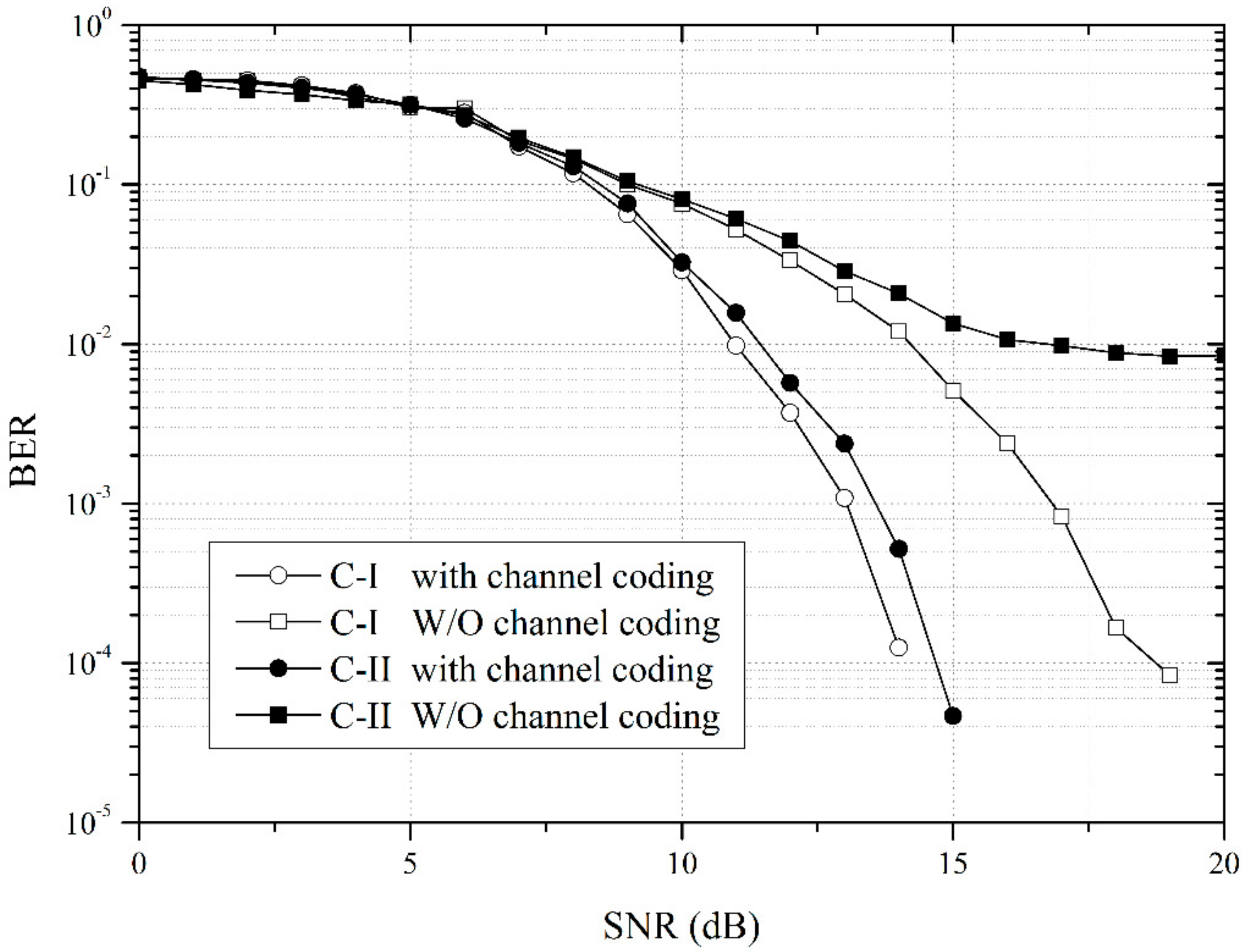
Figure 5 presents the BER performance of CSBM for both Case-I and Case-II, with and without channel coding, respectively [
15]. We can see that, unlike in Case I, the BER performance of Case II deteriorates without channel coding because of the burst errors occurring during the transition period when the transmitter does not send the target color. However, with channel coding, BER performance is improved by minimizing the random and burst errors, and the improved result is almost similar to that of Case-I.
We used MATLAB to simulate our proposed system. The simulation model is represented in
Figure 6 [
14]. First, a built-in MATLAB function was used to generate random data. FEC coding (1/2 convolutional coding) and interleaving were then adopted for the input data bits. Following GCM mapping, the data bits were mapped onto LED modules. Because AWGN is used as noise in our model, it was added to the transmitted data. We model the AWGN depending on channel SNR using MATLAB. On the receiver side, deinterleaving and Viterbi decoding were used after GCM demapping to retrieve the data. The Euclidean distance was used for symbol decision during the GCM demapping process. Finally, the received data is compared with the transmitted data to calculate the BER.
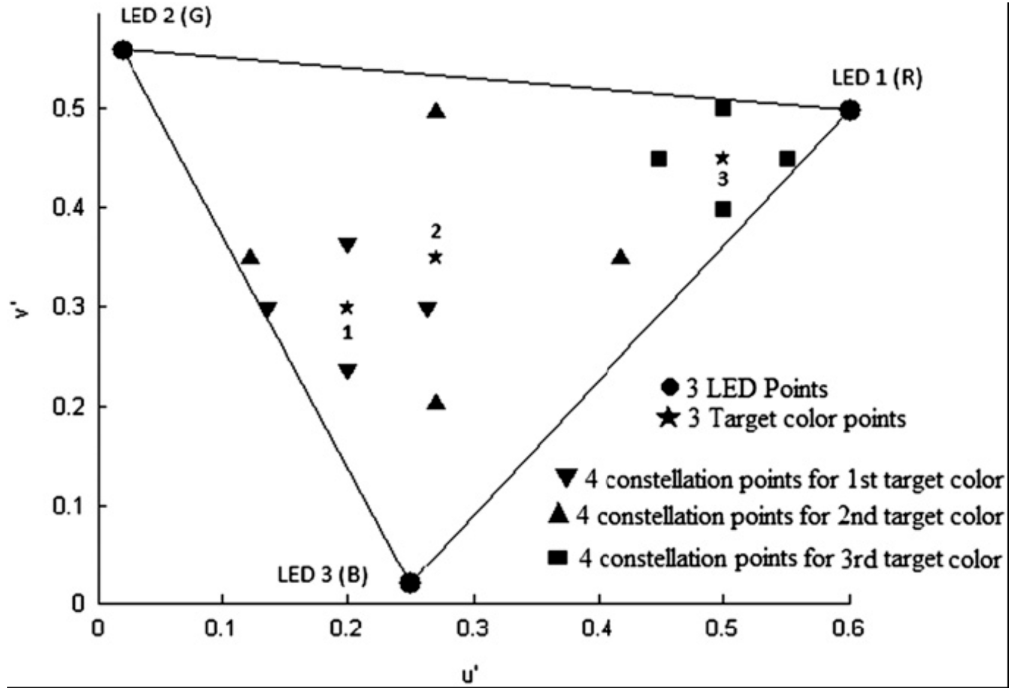
Figure 7 presents the generation of three target colors for the transmitter and their corresponding symbols in the CIELUV color space [
13,
14].
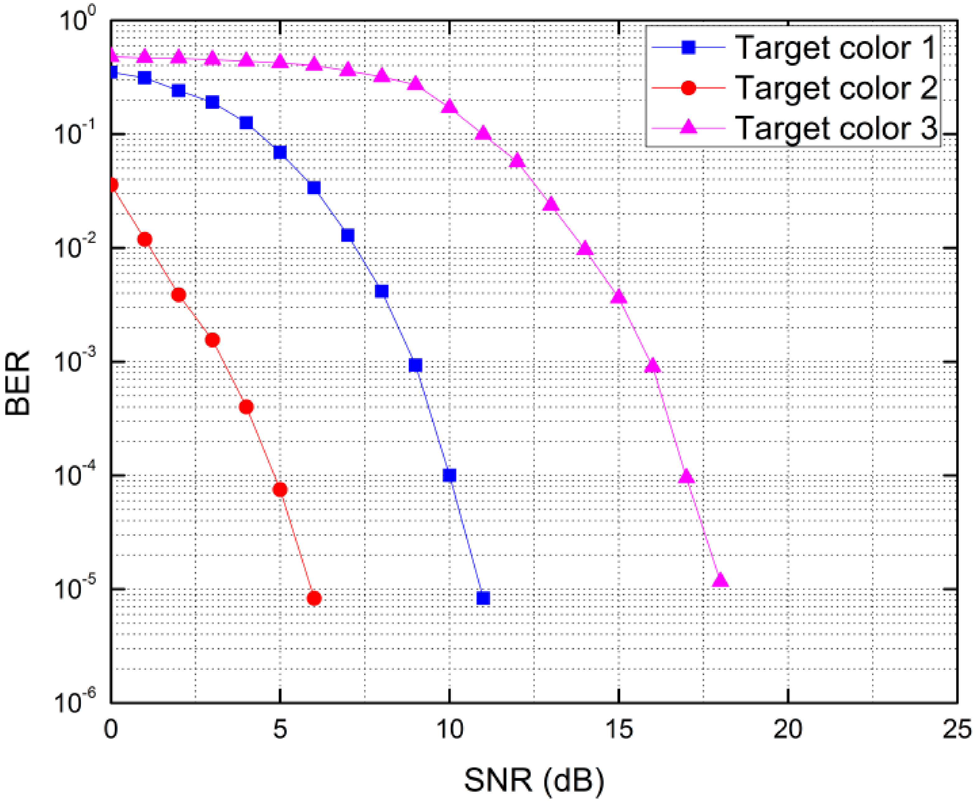
Figure 8 displays the BER performance for the three single target colors [
13,
14]. BER performance differs noticeably because of the different sizes of the constellation diagrams for each target color.
5. Visual MIMO with Color-Space-Based Modulation
In a past paper [
17], it was shown that higher data rates are possible in long-range transmissions for mobile optical communications by a camera using the concept “visual-MIMO”. According to the concept, the optical transmission of a light-emitting array is received by the photodetector elements (i.e., pixels) of a camera. The image sensor of a camera consists of these pixels, defined as an array of receiver which is inherently highly directional. This system provides a degree of freedom in selecting and combining a subset of receiver elements that receive a strong signal from the transmitter and have a large SNR. Conceptually, this visual MIMO system may be quite similar to RF-MIMO antenna selection, but visual-MIMO has less overhead and less complexity to process at the camera receiver due to the use of image processing and computer vision algorithms [
17].
Figure 9 presents the color-independent visual-MIMO communication system [
23,
24]. GCM-based visual-MIMO helps to achieve better performance in terms of SER than conventional light-emitting diode (LED) communication. Using this scheme, it is possible to transmit different colors (symbols) at the same time through LED array. Most importantly, the proposed visual -MIMO system can easily adapt to changes in the target color via image processing [
23,
24].
In general, the capacity of a color-independent visual MIMO system depends on the number of bits per symbol, the array size (
), and the frame rate of the camera. The capacity of the proposed system is defined as,
where
.
6. Time-Sharing-Based Synchronization for Color-Independent Visual-MIMO
An appropriate synchronization method for a color-independent visual-MIMO system was proposed previously [
25]. Usually, LEDs send data at much higher speeds than the camera’s frame rate. To solve this problem, we proposed an effective method of synchronization by time sharing information data with synchronization data, even though the camera frame rate is much lower than the desired data rate [
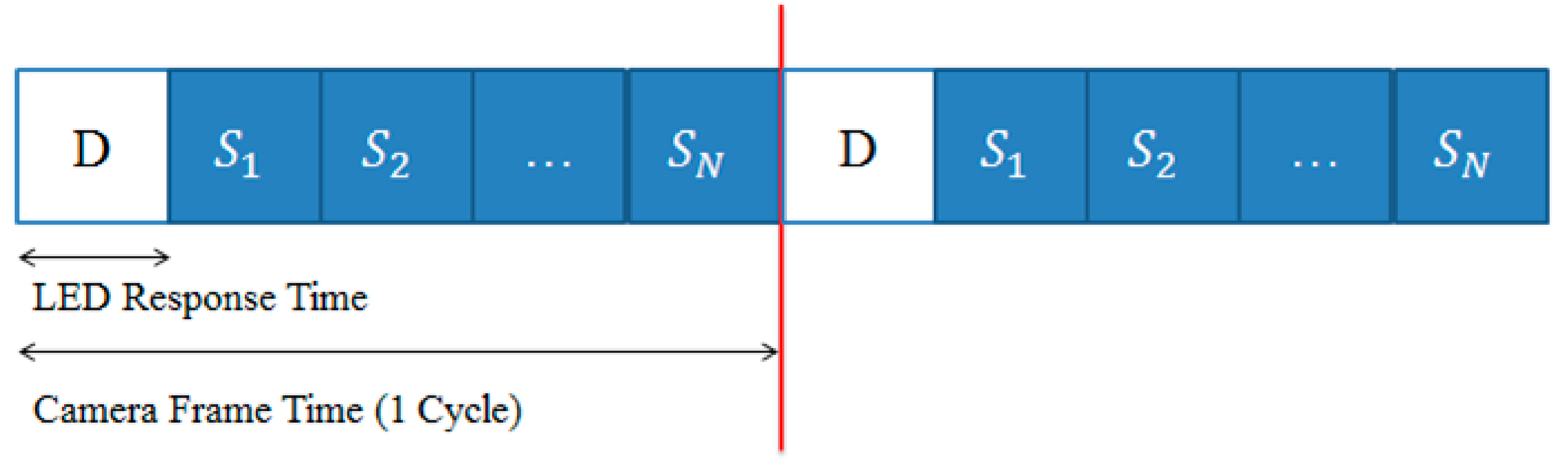
25]. We were able to generate information and synchronization data as shown in
Figure 10 without violating the purpose of GCM [
25].
The white (D) and blue (S) sections represent information symbol (color) data and synchronization data, respectively. Here,
are symbols generated from the color-space-based constellation.
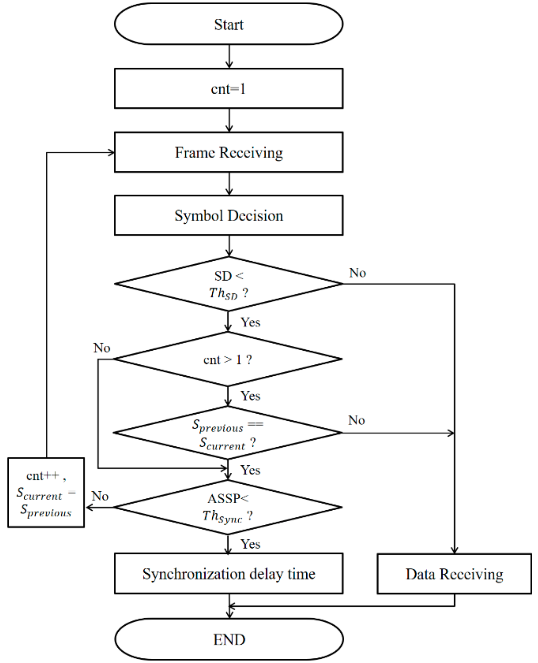
Figure 11 presents the synchronization flow chart for a color independent visual-MIMO system on the receiver side [
25].
This time-sharing-based synchronization can overcome synchronization and flickering problems in a color-independent visual-MIMO system. While maintaining the uniformity of color, synchronization is possible when the LEDs flicker at a higher rate than the camera’s frame rate. This is an advantage for the human eye in that it is not able to detect this high-speed flickering. Therefore, this method not only maintains the function of the desired lighting source but also presents the possibility of communication with commercial cameras.
7. Case Studies of Color-Independent Visual-MIMO
Various applications are possible for visual-MIMO based communication. For example, novel advertising systems may use smartphone cameras to receive product information from electronic billboards. In addition, in museums, kiosks can display information for cell phone cameras, such as maps, images, and customized audio tours. This kind of communication system can also be used in vehicle-to-vehicle (or road), robot-to-robot, and hand-held displays to fixed surveillance cameras. In this section, we will discuss two applications of a color-independent visual-MIMO system: (1) fusion research combining fashion and technology and (2) V2X communication.
7.1. Wearable Visual MIMO
With the growth in the wearable device market, various wearable devices have utilized LEDs for wearable interaction. This is an attempt to combine color-space-based visual-MIMO systems with wearable devices in order to extend the use of LEDs in existing wearable devices to user-oriented interaction.
The design of LED light, which is a practical medium for the transmission of data in a VLC system, must be carefully considered because of its visible characteristics. Most of the existing VLC systems have been based on the use of white light, so the technology should not be simply applied to wearable devices (i.e., fashionable design) as it is. Communication using RGB LEDs, which are used in wearable devices, can be controlled by two parameters: lighting color and brightness. However, for designers, determining the color and brightness of an LED to be embedded in wearable smart fashion is a very important design issue. Thus, because the color and brightness of the light can vary in accordance with the fashion designer’s wishes, seamless communication should be guaranteed for all variations of color and brightness. Given these factors, the color independency of GCM is an essential feature for fashion design. Designers can choose the color and brightness for their design, and engineers can use GCM to set the symbol color to match the chosen color and brightness.
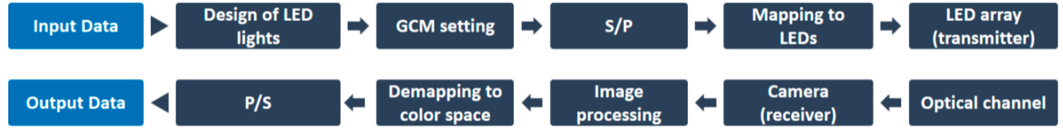
Figure 12 presents a transceiving block diagram of a GCM-based color-independent visual-MIMO system with the addition of an LED light design stage [
26].
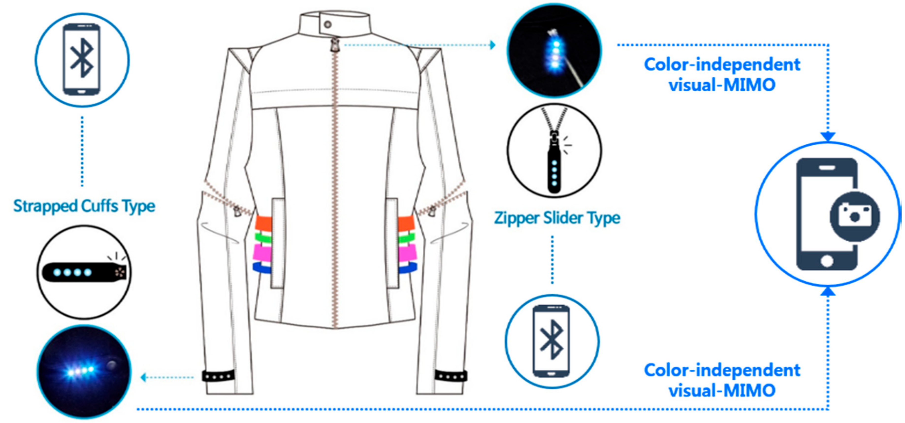
Figure 13 displays a fashion smart module using fasteners based on a color-independent visual-MIMO platform that is currently under development [
26]. The LED array embedded in the strapped cuffs and the zipper slider acts as transmitter for the visual-MIMO system, and the data to be transmitted can be controlled using a smartphone connected with Bluetooth. The transmitted data can be received via a separate device (e.g., a smartphone) with a built-in camera.
The color-independent visual MIMO platform combined with wearable devices is expected to become another means by which users can express their personality in the customized and user-centered wearable device market. For this purpose, the systematic development of software algorithms and hardware design is required for the adaptive application of this technology to various wearable devices in clothing, shoes, and accessories.
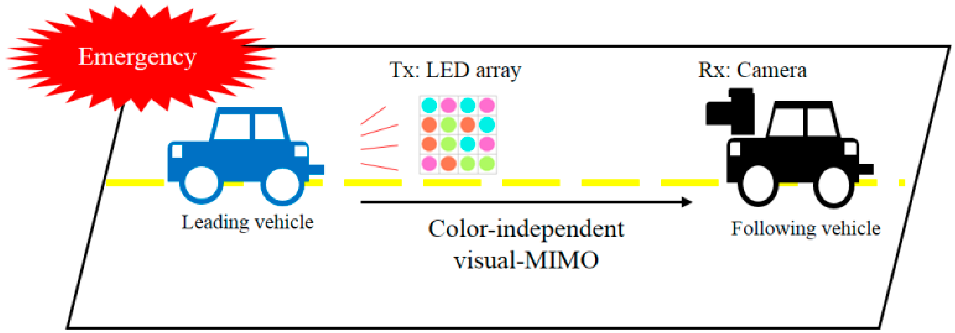
7.2. V2X Communication
The communication between a vehicle and other devices is another application of visual-MIMO systems. This approach has been described in our research work [
23].
Figure 14 shows an example of V2X communication. We proposed two methods for V2X communication using visual-MIMO networking: multipath transmission and multinode (multiple access) communication. Multipath transmission can be used when the distance between the source and destination is far. Information transmitted to the destination node can be relayed via other nodes. For example, a relay vehicle can be used to transfer data. This feature of the network allows multipath transmission, similar to cooperative RF communication, but with lower coordination overhead [
23]. We may also consider another multiple access communication in which a destination node can receive the information from multiple source nodes simultaneously. If the light sources of multiple nodes do not overlap within the field of view of the camera during V2X communication, it is possible to receive each light source by separating multiple sources through image processing techniques. To avoid the overlap of the multiple light sources, a divided region of interest (ROI) method by dividing communication area has been proposed [
23]. Then, we may achieve the simultaneous multiple access communication without interchannel (inter-node) interferences.
8. Future Research
LED color detection is a challenge in visual-MIMO systems. In a past paper [
27], we used regression analysis in LED color detection for both high and low environmental light intensities, representing a simple machine-learning approach. In this strategy, we first detected each LED image from the whole LED array image. We then manually extracted some features for training the LED images to establish a multiple linear regression model. Finally, we obtained the multiple linear regression model to predict the color of the LED images. Using our trained multiple linear regression model, the color closeness accuracy was close to 90% for high and low environmental light intensities. For this work, we designed an experimental setup with a smartphone camera as a receiver, a light meter (CL-200A) for measuring environmental light intensity, and two tripods to fix the smartphone and transmitter in front of two light sources in a dark black room. The distance between the transmitter and smartphone was 30 cm. The details of the experimental setup and measurements are described in our previous work [
27]. Based on this research [
27], it is clear that machine learning is a promising approach for the visual-MIMO system. In the near future, this machine-learning approach can be used to predict LED color from LED images based on the distance and angle between the transmitter and receiver for different environmental light intensities. We also intend to measure and analyze the communication performance of this approach.
Visual-MIMO is the part of the VLC system. We have given some examples of visual-MIMO communication systems. Other researchers [
28,
29,
30] focus on the sustainability of the indoor VLC in heterogeneous network. They pointed out technical challenges like handover, resource management, interference minimization, and optimization of channel capacity in this field. These topics are prominent to establish a complete network using VLC combining with an RF network. In the future, we will survey the suitability of our visual-MIMO scheme in indoor applications by considering above mentioned challenges.
9. Conclusions
In this paper, we first reviewed the design and performance of color-space-based modulation for a VLC system that is independent of the target color. This included a summary of current universal manipulation methods, such as color space selection, constellation generation, and mapping-demapping processes, that are uniquely suitable for the manipulation of light signals in the transceiving of data in typical VLC systems. We then described our research works which we underwent with the goal of achieving a color-independent visual-MIMO system that incorporates all of the advantages of GCM, generating higher data rates over larger distances, and improving performance by using image processing in addition to color independency. Besides, we described an algorithm for time-sharing-based synchronization that is vital for LED array-to-camera communication. We also demonstrated two practical applications of a GCM-based visual-MIMO system. Finally, we were able to establish that machine learning could be useful component of GCM based visual MIMO communication.
Author Contributions
The manuscript had been written by T.-H.K; he also designed the experiments. J.-E.K. helped to perform the experiments as well as analyze the results. Y.-H.K described the fusion research combining the color-space-based visual-MIMO systems with wearable devices. As the corresponding author, K.-D.K. proposed the idea as well as supervised the research; he wrote the manuscript.
Funding
This research was supported by the Basic Science Research Program through the National Research Foundation (NRF) of Korea funded by the Ministry of Education [2015R1D1A1A01061396] and was also supported by the National Research Foundation of Korea Grant funded by the Ministry of Science, ICT, Future Planning [2015R1A5A7037615].
Conflicts of Interest
The authors declare no conflicts of interest.
References
- Komine, T.; Nakagawa, M. Fundamental Analysis for Visible-Light Communication System using LED Lights. IEEE Trans. Consum. Electron. 2004, 50, 100–107. [Google Scholar] [CrossRef]
- Elgala, H.; Mesleh, R.; Haas, H. Indoor Optical Wireless Communication: Potential and State-of-the-Art. IEEE Commun. Mag. 2011, 41, 56–62. [Google Scholar] [CrossRef]
- Ergul, O.; Dinc, E.; Akan, O.B. Communicate to illuminate: State-of-the-art and research challenges for visible light communications. Phys. Commun. 2015, 17, 72–85. [Google Scholar] [CrossRef]
- Lee, K.; Park, H. Modulations for visible light communications with dimming control. IEEE Photonics Technol. Lett. 2011, 23, 1136–1138. [Google Scholar] [CrossRef]
- Anand, J.M.; Mishra, P. A novel modulation scheme for visible light communication. In Proceedings of the 2010 Annual IEEE India Conference (INDICON), Kolkata, India, 17–19 December 2010; pp. 1–3. [Google Scholar] [CrossRef]
- Hashemi, S.K.; Ghassemlooy, Z.; Chao, L.; Benhaddou, D. Orthogonal frequency division multiplexing for indoor optical wireless communications using visible light LEDs. In Proceedings of the 2008 6th International Symposium on Communication Systems, Networks and Digital Signal Processing (CSNDSP), Graz, Austria, 25 July 2008; pp. 174–178. [Google Scholar] [CrossRef]
- Afgani, M.Z.; Haas, H.; Elgala, H.; Knipp, D. Visible light communication using OFDM. In Proceedings of the 2nd International Conference on Testbeds and Research Infrastructures for the Development of Networks and Communities (TRIDENTCOM 2006), Barcelona, Spain, 1–3 March 2006. [Google Scholar] [CrossRef]
- Sugiyama, H.; Haruyama, S.; Nakagawa, M. Experimental investigation of modulation method for visible-light communication. IEICE Trans. Commun. 2006, E89-B, 3393–3400. [Google Scholar] [CrossRef]
- Khan, T.A.; Tahir, M.; Usman, A. Visible light communication using wavelength division multiplexing for smart spaces. In Proceedings of the 2012 IEEE Consumer Communications and Networking Conference (CCNC), Las Vegas, NV, USA, 14–17 January 2012; pp. 230–234. [Google Scholar] [CrossRef]
- Yokoi, A.; Samsung Yokoham Research Institute. Color multiplex coding for VLC. In IEEE P802.15 Working Group for Wireless Personal Area Networks (WPANs); Institute of Electrical and Electronics Engineers (IEEE): Piscataway, NJ, USA, 2008. [Google Scholar]
- IEEE Standard for Local and Metropolitan Area Networks—Part 15.7: Short-Range Wireless Optical Communication Using Visible Light. IEEE Stand. 802.15.7 2011. [CrossRef]
- Drost, R.J.; Sadler, B.M. Constellation design for color-shift keying using billiards algorithms. In Proceedings of the 2010 IEEE GLOBECOM Workshops (GC Wkshps), Miami, FL, USA, 6–10 December 2010; pp. 980–984. [Google Scholar] [CrossRef]
- Das, P.; Kim, B.-Y.; Park, Y.; Kim, K.-D. A New Color Space Based Constellation Diagram and Modulation Scheme for Color Independent VLC. Adv. Electr. Comput. Eng. 2012, 12, 11–18. [Google Scholar] [CrossRef]
- Das, P.; Kim, B.-Y.; Park, Y.; Kim, K.-D. Color-independent VLC based on a color space without sending target color information. Opt. Commun. 2013, 286, 69–73. [Google Scholar] [CrossRef]
- Das, P.; Park, Y.; Kim, K.-D. Performance improvement of color space based VLC modulation schemes under color and intensity variation. Opt. Commun. 2013, 303, 1–7. [Google Scholar] [CrossRef]
- Das, P.; Park, Y.; Kim, K.-D. Performance analysis of color-independent visible light communication using a color-space-based constellation diagram and modulation scheme. Wirel. Pers. Commun. 2014, 74, 665–682. [Google Scholar] [CrossRef]
- Ashok, A.; Gruteser, M.; Mandayam, N.B.; Silva, J.; Dana, K.; Varga, M. Challenge: Mobile optical networks through visual MIMO. In Proceedings of the MobiCom’10: Sixteenth Annual International Conference on Mobile Computing and Networking, Chicago, IL, USA, 20–24 September 2010; pp. 105–112. [Google Scholar]
- Ashokz, A.; Gruteserz, M.; Mandayamz, N.; Dana, K. Characterizing Multiplexing and Diversity in Visual MIMO. In Proceedings of the 45th Annual Conference on Information Sciences and Systems (CISS), Baltimore, MD, USA, 23–25 March 2011; pp. 1–6. [Google Scholar] [CrossRef]
- Berns, R.S. Billmeyer and Saltzman’s Principles of Color: Technology, 3rd ed.; Wiley: New York, NY, USA, 2000; Chapter 2; ISBN 978-0-471-19459-0. [Google Scholar]
- Elgala, H.; Mesleh, R.; Haas, H.; Pricope, B. OFDM visible light wireless communication based on white LEDs. In Proceedings of the 2007 IEEE 65th Vehicular Technology Conference—VTC2007-Spring, Dublin, Ireland, 22–25 April 2007; pp. 2185–2189. [Google Scholar] [CrossRef]
- Lee, D.; Choi, K.; Kim, K.-D.; Park, Y. Visible light wireless communication based on predistorted OFDM. Opt. Commun. 2012, 285, 1767–1770. [Google Scholar] [CrossRef]
- Das, P.; Park, Y.; Kim, K.-D. Performance of color-independent OFDM visible light communication based on color space. Opt. Commun. 2014, 324, 264–268. [Google Scholar] [CrossRef]
- Kim, J.-E.; Kim, J.-W.; Park, Y.; Kim, K.-D. Color-Space-Based Visual-MIMO for V2X Communication. Sensors 2016, 16, E591. [Google Scholar] [CrossRef] [PubMed]
- Kim, J.-E.; Kim, J.-W.; Kim, K.-D. LEA Detection and Tracking Method for Color-Independent Visual-MIMO. Sensors 2016, 16, 1027. [Google Scholar] [CrossRef] [PubMed]
- Kwon, T.-H.; Kim, J.-E.; Kim, K.-D. Time-Sharing-Based Synchronization and Performance Evaluation of Color-Independent Visual-MIMO Communication. Sensors 2018, 18, E1553. [Google Scholar] [CrossRef] [PubMed]
- Kim, J.-E.; Kim, Y.-H.; Oh, J.-H.; Kim, K.-D. Interactive Smart Fashion using User-oriented Visible-Light Communication: The Case of Modular Strapped Cuffs and Zipper Slider Types. Wirel. Commun. Mob. Comput. 2017, 2017, 1–13. [Google Scholar] [CrossRef]
- Banik, P.P.; Saha, R.; Kim, K.-D. Regression analysis for LED color detection of visual-MIMO system. Opt. Commun. 2018, 413, 121–130. [Google Scholar] [CrossRef]
- Seguel, F.; Soto, I.; Iturralde, D.; Adasme, P.; Nuñez, B. Enhancement of the QoS in an OFDMA/VLC system. In Proceedings of the 2016 10th International Symposium on Communication Systems, Networks and Digital Signal Processing (CSNDSP), Prague, Czech Republic, 20–22 July 2016; pp. 1–5. [Google Scholar] [CrossRef]
- Tsiropoulou, E.E.; Vamvakas, P.; Papavassiliou, S. Resource Allocation in Next-Generation Broadband Wireless Access Networks; Singhal, C., De, S., Eds.; IGI Global: Hershey, PA, USA, 2017; Chapter 10. [Google Scholar]
- Lin, B.; Tang, X.; Ghassemlooy, Z.; Lin, C.; Li, Y. Experimental Demonstration of an Indoor VLC Positioning System Based on OFDMA. IEEE Photonics J. 2017, 9, 1–9. [Google Scholar] [CrossRef]
© 2018 by the authors. Licensee MDPI, Basel, Switzerland. This article is an open access article distributed under the terms and conditions of the Creative Commons Attribution (CC BY) license (http://creativecommons.org/licenses/by/4.0/).


