Article

Feedforward Control Based on Error and Disturbance Observation for the CCD and Fiber-Optic Gyroscope-Based Mobile Optoelectronic Tracking System

1
Institute of Optics and Electronics, Chinese Academy of Science, Chengdu 610209, China
2
Key Laboratory of Optical Engineering, Chinese Academy of Sciences, Chengdu 610209, China
3
University of Chinese Academy of Sciences, Beijing 100039, China
*
Author to whom correspondence should be addressed.
Electronics 2018, 7(10), 223; https://doi.org/10.3390/electronics7100223
Submission received: 23 August 2018 / Revised: 24 September 2018 / Accepted: 26 September 2018 / Published: 29 September 2018
(This article belongs to the Special Issue Visible Light Communication and Positioning)

Abstract

:
In the mobile optoelectronic tracking system (MOTS) based on charge-coupled device (CCD) and fiber-optic gyroscope (FOG), the tracking performance (TP) and anti-disturbance ability (ADA) characterized by boresight error are of equal importance. Generally, the position tracking loop, limited by the image integration time of CCD, would be subject to a non-negligible delay and low-sampling rate, which could not minimize the boresight error. Although the FOG-based velocity loop could enhance the ADA of the system, it is still insufficient in the case of some uncertain disturbances. In this paper, a feedforward control method based on the results of error and disturbance observation was proposed. The error observer (EOB) based on the CCD data and model output essentially combined the low-frequency tracking feedforward and closed-loop disturbance observer (DOB), which could simultaneously enhance the low-frequency TP and ADA. In addition, in view of the poor low-frequency performance of the FOG due to drift and noise that may result in the inaccuracy of the observed low-frequency disturbance, the FOG-based DOB was used to improve the relatively high-frequency ADA. The proposed method could make EOB and DOB complementary and help to obtain a high-precision MOTS, for in practical engineering, we give more attention to the low-frequency TP and full-band ADA. Simulations and experiments demonstrated that the proposed method was valid and had a much better performance than the traditional velocity and position double-loop control (VPDC).

1. Introduction

The charge-coupled device (CCD)-based mobile optoelectronic tracking system (MOTS), commonly mounted on vehicles, ships, airplanes and satellites, is mainly used for astronomical observation, free space communication, searching and target tracking [1,2,3,4,5]. The closed-loop control of the system is based on the boresight error detected by a CCD. The value of boresight error could reflect the tracking performance (TP) and anti-disturbance ability (ADA), both of which are equally important in a moving platform being full of various disturbances. Due to the image integration time of the CCD, the position tracking loop would be subject to a non-negligible delay and low-sampling rate [6,7], which are major causes of instability and performance deterioration [8,9,10]. Scholars have adopted many optimization methods to enhance the tracking accuracy and decrease the bad influence of the delay. A PID-I method, with an integration added to the controller, was proposed to reduce the steady-state error of the system [11], which, however, would affect the stability of the system and decrease its dynamic performance. In order to eliminate the effect of delay on system stability, a Smith predictor was introduced to the tracking loop [12,13]; however, the delay was moved out from the closed loop but still existed in the system, which would restrict the TP. As reported, a multi-loop control structure based on MEMS inertial sensors could increase the bandwidth of the system [14]. Nevertheless, there was little low-frequency improvement of TP. Compared to the difficulties in enhancing the TP, the ADA of the system is relatively easier to improve, for the disturbances usually originate from the base which could be measured by inertial sensors with little delay. Therefore, an inertial sensor, such as a fiber-optic gyroscope (FOG) mounted parallel to the boresight, is commonly used to establish a high-rate inner loop, which would increase the whole ADA of the system [15,16]. However, the ADA of the closed-loop control is still insufficient for plant uncertainties and large-magnitude disturbances. In summary, the feedback control method is limited in improving either the TP or ADA of the system.
In order to get a satisfactory performance, it is necessary to perform feedforward control, including the tracking and disturbance feedforward. Theoretically, the errors could be significantly reduced or even eliminated, and almost all measurable disturbances could be suppressed. Unfortunately, it was difficult to get the trajectory of the target and extract the disturbance signals. A predictive tracking method combining the boresight error with angular sensor for synthesizing the target trajectory was proposed to compensate the errors caused by time delay [17,18]. However, an additional position sensor was required, which was only suitable for the condition with low measurement noise. Similarly, in order to detect the disturbances, additional sensors should be equipped on the pedestal [19,20]; the wind disturbance and cogging force cannot be reflected from the pedestal. Hence, the feedforward control based on direct measurement could not be easily implemented, especially for the space and cost limited occasions.
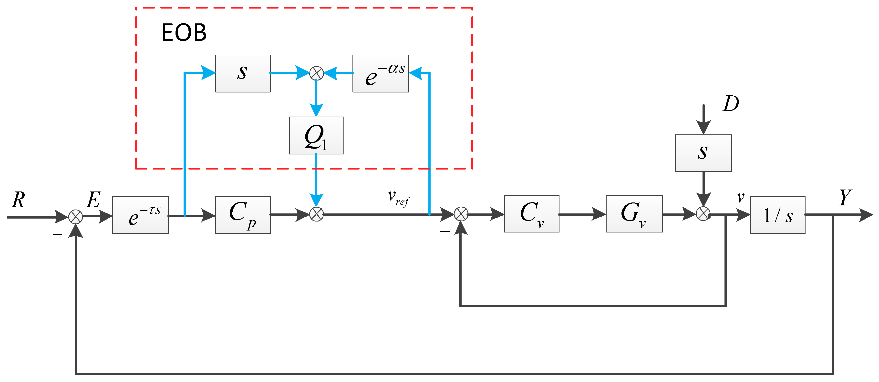
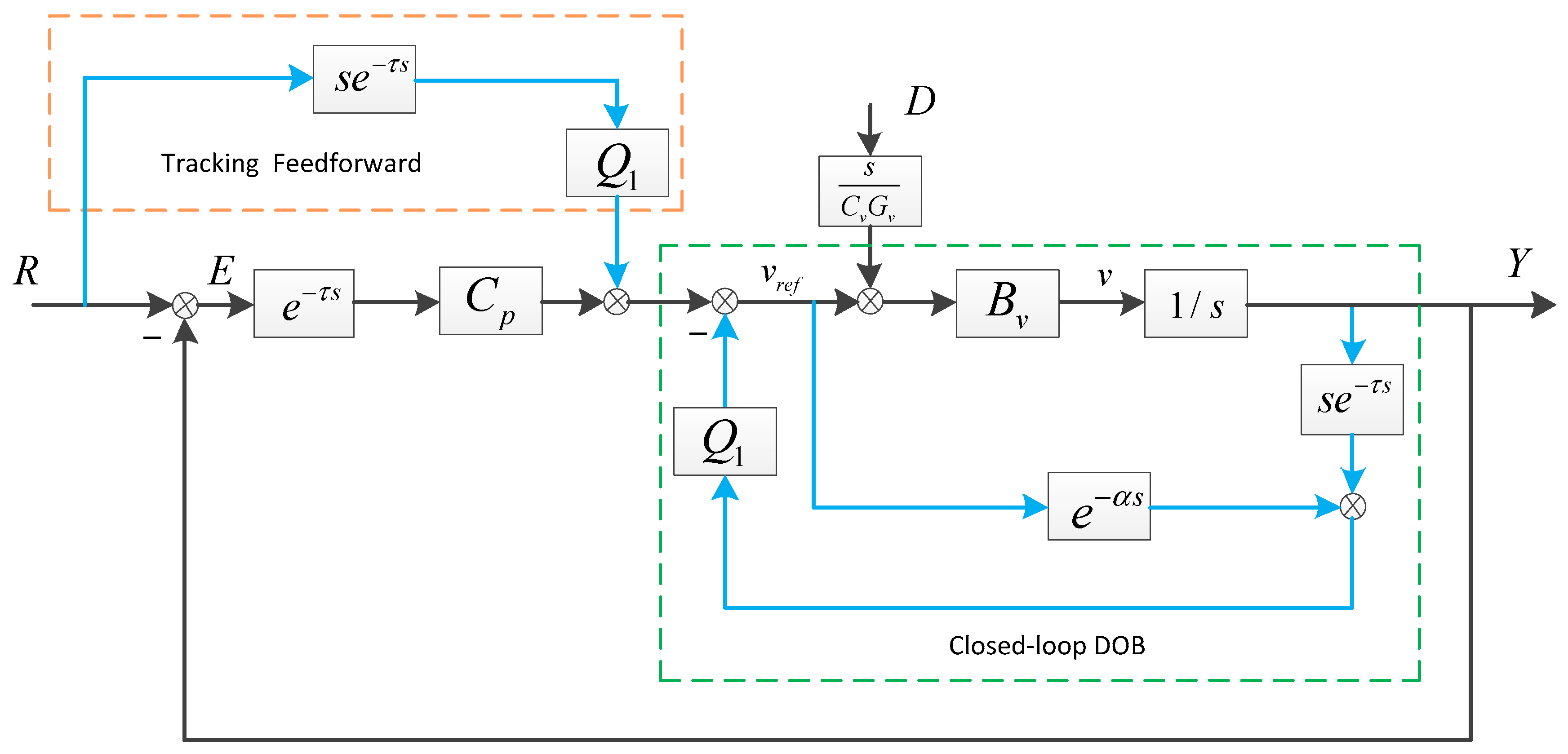
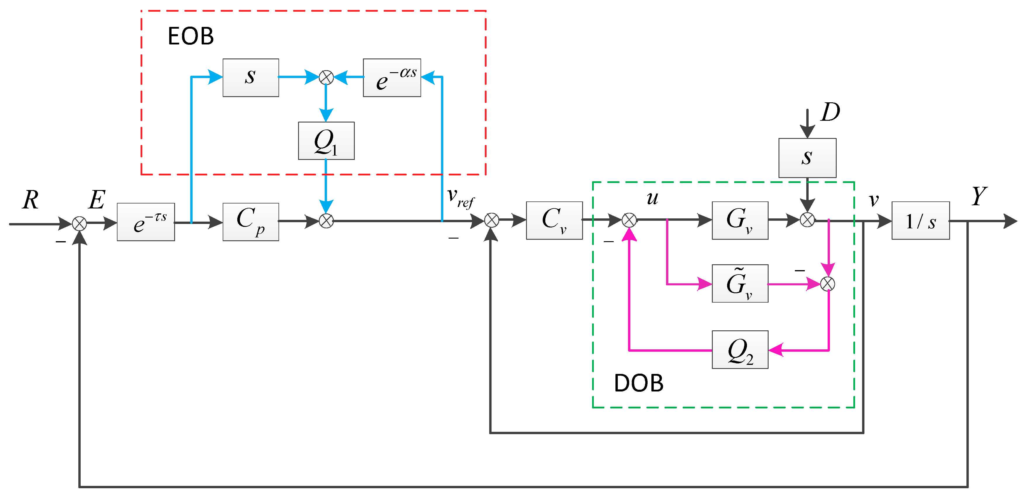
In this paper, an unconventional feedforward control method based on the error and disturbance observation was proposed considering the velocity and position double-loop control (VPDC). The CCD-based error observer (EOB) combined the differential of the boresight error and model output with a delay to generate a composite velocity, which simultaneously contained the delayed signals of the target motion and disturbance. Since the delay had little effect on the very low-frequency signal, the low-frequency items of the composite velocity could be fed forward to the velocity closed loop. The EOB was equivalent to a coalition of the low-frequency tracking and disturbance feedforward. Although the TP improvement was in the low frequency, it was satisfactory because the target motion signal mainly distributed there. Unlike the TP, the ADA improvement only in low frequency brought by EOB was not enough because external disturbances nearly distributed in the full frequency band. Therefore, a FOG-based disturbance observer (DOB) was continuously added to the inner loop to increase the ADA. Unlike the direct disturbance feedforward method, by which additional sensors should be equipped on the pedestal to extract disturbance, DOB could acquire the disturbance through the difference between the data of the existing sensors and the model output [21,22]. Since the FOG’s low-frequency signal was weak and susceptible to drift and noise, which resulted in the inaccuracy of the observed low-frequency disturbance, the additional DOB mainly benefited the high-frequency ADA. Hence, the proposed method could make the CCD-based EOB and FOG-based DOB complementary. To verify the effectiveness of the method, a platform consisting of groups of the fast steering mirror system was established, which was the core component of MOTS [14]. Experiments demonstrated that the proposed system had a good TP in low frequency and a strong ADA in a wide band.
This paper is organized as follows. Section 2 introduces the physical structure of the MOTS, the basic VPDC method and the common tracking and disturbance feedforward way based on direct measurement. Section 3 analyzes the proposed feedforward method based on the EOB and DOB, which could provide theoretical derivations. Section 4.1 discusses the matter of how to design the EOB controller Q 1 to maximize the performance of the EOB under the condition of guaranteed gain and phase margin. Section 4.2 focuses on the design of the DOB controller Q 2 and analyzes the promotion of ADA. Section 5 is the experimental part, indicating the detailed improvement of the TP and ADA by the proposed method. Section 6 lists the concluding remarks.

2. The CCD-Based MOTS with Traditional Control Methods

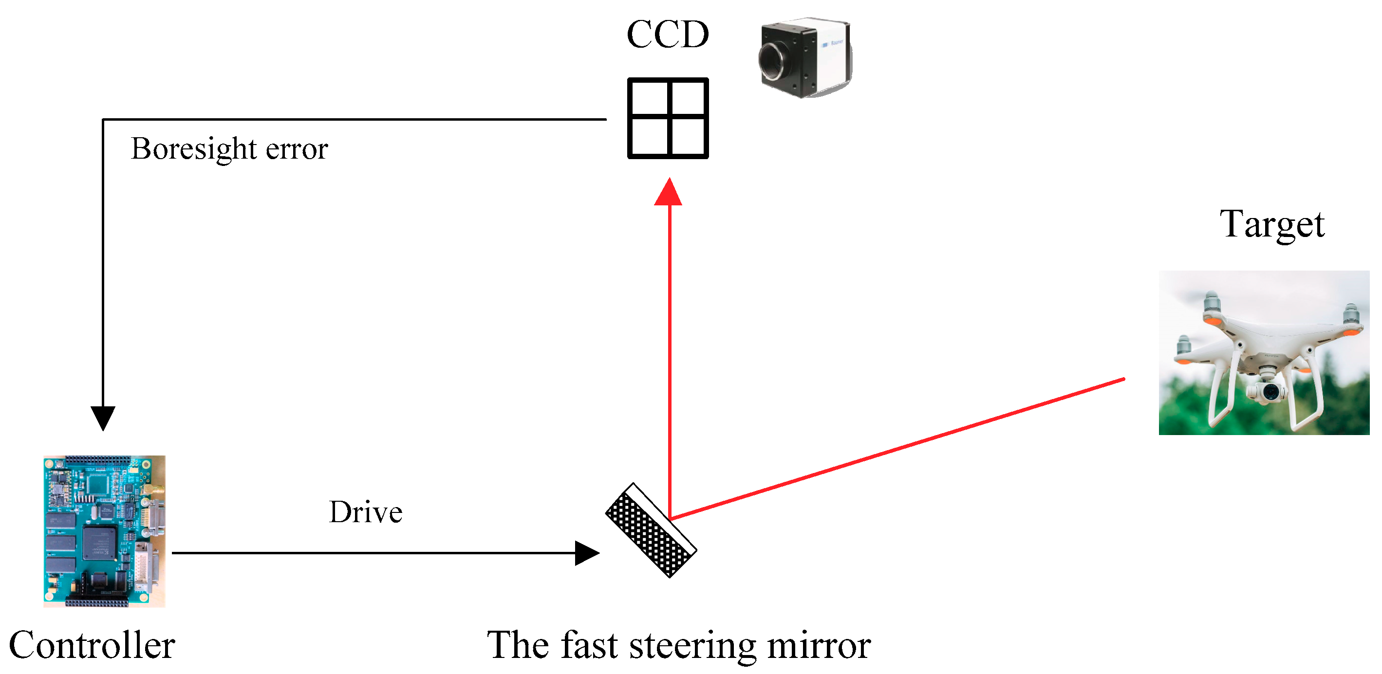
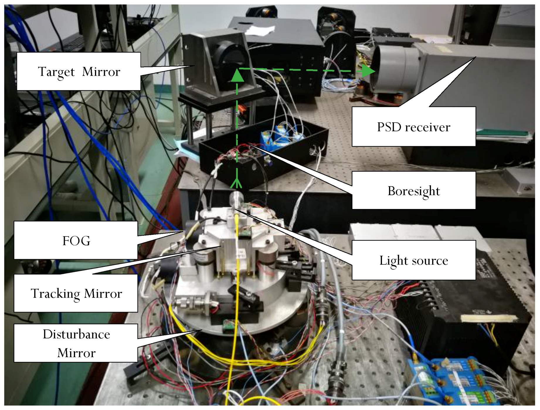
The basic configuration of the MOTS is shown in Figure 1. The light from the target could pass through the reflective surface of the rotating mirror, which would then be detected by CCD to calculate the boresight error. After receiving the boresight error, the controller would drive the voice motors to make the mirror rotate accordingly, thereby tracking the target and resisting the impact of the external disturbances. To enhance the ADA, a FOG was mounted on the lens barrel to measure the angle velocity. In addition, the velocity closed loop would increase the stiffness of the object and make it easier to control the platform.

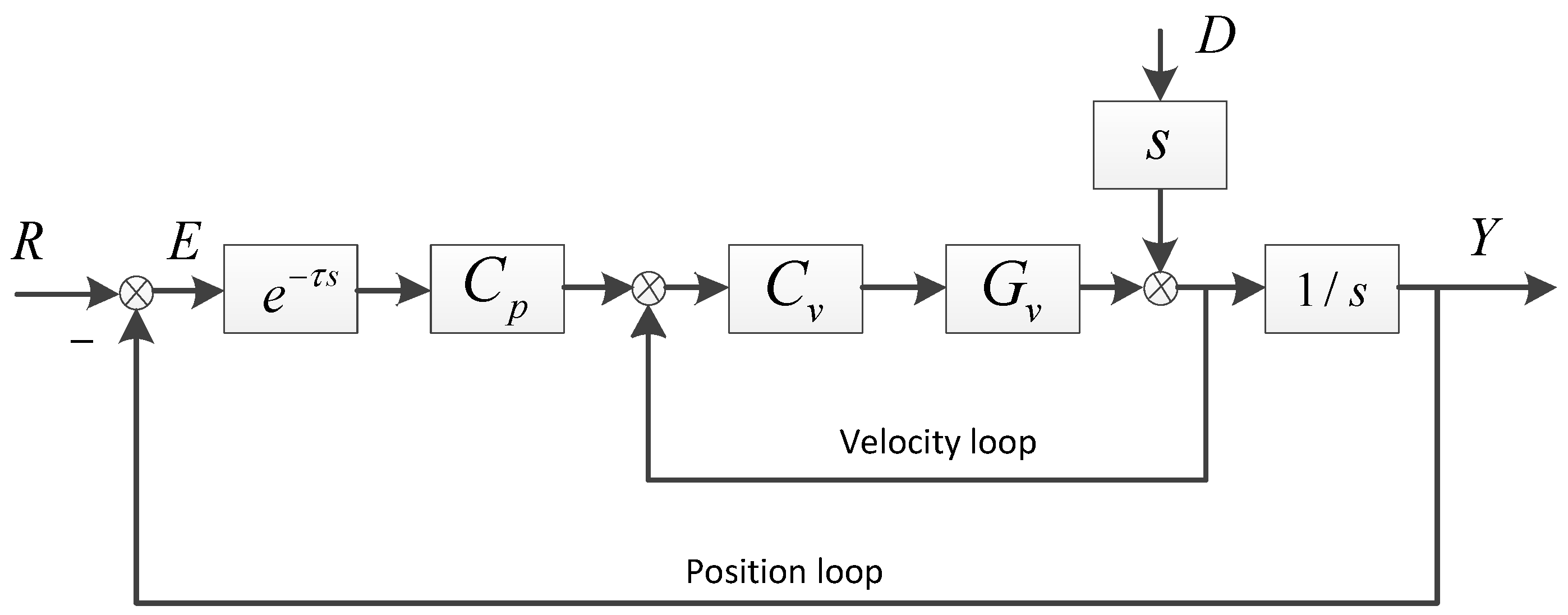
2.1. The Basic VPDC Control Method

In Figure 2, the basic control structure of the VPDC was presented. The error transfer functions of the tracking and disturbance were respectively S R and S D , as shown in Equations (1) and (2).
S R = E R = 1 1 + C p C v G v 1 + C v G v 1 s e τ s 1 1 + C p 1 s e τ s  
S D = E D = 1 1 + C v G v + C p C v G v 1 s e τ s = 1 1 + C v G v 1 1 + C p C v G v 1 + C v G v 1 s e τ s 1 1 + C v G v 1 1 + C p 1 s e τ s
where C v G v / ( 1 + C v G v ) 1 in low frequency, because the high-sampling rate velocity loop commonly has a high bandwidth over 100 Hz [14]. As we all know, the smaller the error transfer function is, the higher the accuracy will be. From Equations (1) and (2), it could be concluded that the TP could be slightly improved by the velocity loop. However, the velocity loop could significantly improve the ADA and the enhanced part is | 1 / ( 1 + C v G v ) | . Unfortunately, when tracking a high-velocity target with strong external disturbance from the pedestal, the TP and ADA would still be insufficient. If the structure was not modified, we could only increase the gain C p and C v or add more integral elements to enhance the performance. However, these would decrease the margin and could even make the system unstable. To get a high-precision system under complex conditions, the feedforward branch should be introduced.

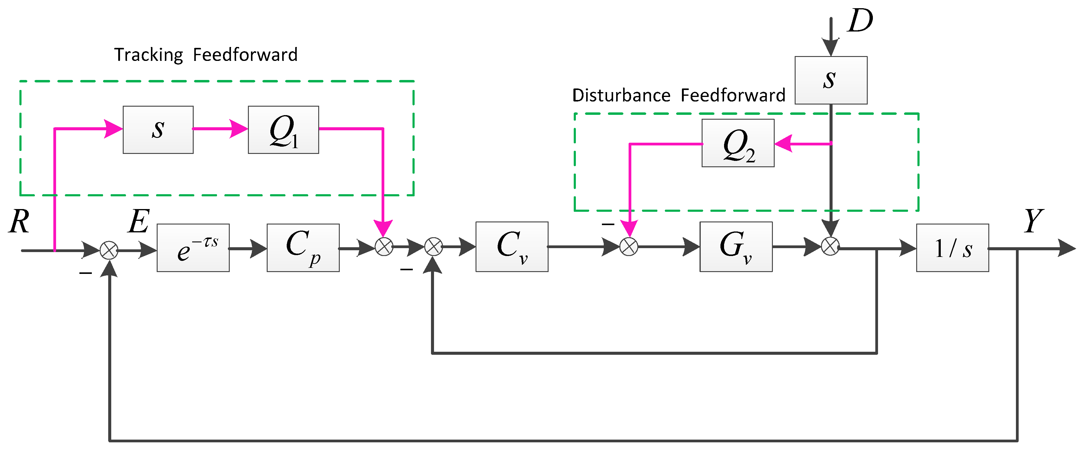
2.2. The Conventional Feedforward Based on Direct Measurement

The feedforward control, as a robust method in industrial control, can effectively decrease the influence of delay and establish a high real-time and high-precision system. The VPDC-based direct feedforward structure is shown below (Figure 3).
The error transfer functions are as follows.
S R = E R = 1 Q 1 C v G v 1 + C v G v 1 + C p C v G v 1 + C v G v 1 s e τ s 1 Q 1 1 + C p 1 s e τ s  
S D = E D = 1 Q 2 G v 1 + C v G v + C p C v G v 1 s e τ s = 1 1 + C v G v 1 Q 2 G v 1 + C p C v G v 1 + C v G v 1 s e τ s 1 1 + C v G v 1 Q 2 G v 1 + C p 1 s e τ s
Compared to Equations (1) and (2), if Q 1 and Q 2 are designed properly, the error could be reduced to 0, theoretically. However, in fact, the pure feedforward control is a kind of open-loop control highly relying on the object model. Since the mathematical model could only be built accurately at low and middle frequencies, the promotion mainly concentrated in these bands. In addition, it was difficult to get signals of the target movement and disturbance. Firstly, there is no sensor that could directly detect the motion state of the target. If the sensors’ fusion method is adopted to predict the target trajectory, an additional sensor should be used to measure the position of the platform. The prediction method requires lots of computation and is only suitable for low noise environments. Secondly, in order to extract the external disturbance from the pedestal, additional sensors are also required. Moreover, it is difficult to identify the disturbance source and more auxiliary equipments are required. Therefore, the feedforward based on direct measurement is also inappropriate in engineering.

3. The EOB and DOB-Based Indirect Feedforward Control

3.1. The CCD-Based EOB

The proposed way of combining EOB and DOB could be regarded as an indirect feedforward control of model reference. The EOB structure is shown in Figure 4. The inner velocity loop has changed the velocity transfer function and it could be treated as 1 in low frequency. The given velocity v r e f after passing a delay element is actually an output of the inner closed-loop model. Through combining the differential of the boresight error and the model output, a composite velocity is produced, which simultaneously contains the information of the target and disturbances. In order to better understand the essence of the EOB, its equivalent structure, as shown in Figure 5, should be referred to.
In Figure 5, the EOB is split into a tracking feedforward structure and a closed-loop DOB. In the tracking feedforward, the input of Q 1 refers to the target’s velocity with the delay of CCD. Similarly, the input of Q 1 in DOB refers to an external disturbance with a same delay. These delayed signals are valuable, which can be fed forward to the system at a low frequency, because the phase lag caused by delay would be little at the very low frequency. However, at the high frequency, the phase lag would be great, which could lead to instability of the system. Hence, to reduce the negative influence of the delayed input, the low-pass filter Q 1 should be adopted, which would only allow the passing of low-frequency signals. Of course, because of the existing of the delay, the effect of EOB is slightly worse than the direct feedforward way based on sensors fusion, but this still can be accepted. Therefore, EOB is an incomplete feedforward way working at the low frequency.
To get the error transfer functions easier, the EOB in Figure 4 can also be regarded as an equivalent position controller as follows.
C p = s Q 1 + C p 1 Q 1 e α s  
With C p , the error transfer functions in Figure 4 can be derived below.
S R = E R = 1 Q 1 e α s 1 + Q 1 ( C v G v 1 + C v G v e τ s e α s ) + C p C v G v 1 + C v G v 1 s e τ s 1 Q 1 e α s 1 + C p 1 s e τ s
S D = E D = 1 1 + C v G v 1 1 + s Q 1 + C p 1 Q 1 e τ s C v G v 1 + C v G v 1 s e τ s = 1 1 + C v G v 1 Q 1 e α s 1 + Q 1 ( C v G v 1 + C v G v e τ s e α s ) + C p C v G v 1 + C v G v 1 s e τ s 1 1 + C v G v 1 Q 1 e α s 1 + C p 1 s e τ s
Compared to Equations (3) and (4), the values of Equations (6) and (7) could not reach 0 due to the existence of delay. However, it could be close to 0 at the very low frequency, because e α s 1 under this condition. Theoretically, the lower bandwidth of Q 1 could benefit the stability of the system, but the very low frequency would reduce the effect of feedforward. In order to maximize the benefits of the feedforward while ensuring the stability, the matter of how to choose Q 1 with guaranteed gain margin (GM) and phase margin (PM) will be discussed in Section 4.

3.2. The Additional FOG-Based DOB

EOB can apparently enhance the low-frequency TP and ADA. It is adequate to complete the tracking because the main frequencies of the target signal are low. However, the frequencies of external disturbance distribute in a wide band. In addition to the low-frequency sway, the MOTS could also be greatly affected by relatively high-frequency mechanical vibration and electromagnetic interference. Therefore, to further improve the ADA and release the potential of the FOG only used in feedback, the FOG-based DOB was added into the velocity loop. FOG had a high bandwidth over 100 Hz, while at the low frequency, its signal was susceptible to drift and noise. Hence, the DOB could extract an accurate disturbance at the relatively high frequency, which can promote the ADA a lot in the higher band. The structure combining EOB with DOB is presented in Figure 6.
The closed-loop velocity is given as follows
v = u G v + s D  
u = ( v r e f v ) C v ( v u G ˜ v ) Q 2  
After calculation,
v = C v G v 1 + C v G v + Q 2 ( G v G ˜ v ) v r e f + ( 1 Q 2 G ˜ v ) s 1 + C v G v + Q 2 ( G v G ˜ v ) D  
Since E = R 1 s v and v r e f = E e τ s C p , we could get
S ^ R = E R = 1 Q 1 e α s 1 Q 1 e α s + C v G v 1 + C v G v + Q 2 ( G v G ˜ v ) ( C p + s Q 1 ) e τ s 1 s 1 Q 1 e α s 1 Q 1 e α s + ( C p + s Q 1 ) e τ s 1 s 1 Q 1 e α s 1 + C p e τ s 1 s
S ^ D = E D = ( 1 Q 2 G ˜ v ) 1 + C v G v + Q 2 ( G v G ˜ v ) ( 1 Q 1 e α s ) 1 Q 1 e α s + C v G v 1 + C v G v + Q 2 ( G v G ˜ v ) ( C p + s Q 1 ) e τ s 1 s ( 1 Q 2 G ˜ v ) 1 + C v G v + Q 2 ( G v G ˜ v ) ( 1 Q 1 e α s ) 1 Q 1 e α s + ( C p + s Q 1 ) e τ s 1 s ( 1 Q 2 G ˜ v ) 1 + C v G v ( 1 Q 1 e α s ) 1 + C p e τ s 1 s
Equation (11) is approximately equal to Equation (6), which means that the FOG-based DOB could not enhance the TP, but slightly affect the stability of the system. Comparing Equation (12) with Equation (7), it could be obviously found that the ADA was continuously improved. Then, at the low frequency 1 Q 1 e α s was close to 0 and at the relatively high frequency 1 Q 2 G ˜ v was close to 0, which means that the CCD-based EOB and FOG-based DOB could complement each other and a system with strong ADA in a wide band was acquired. The design of Q 1 and Q 2 will be discussed in the following section.

4. Parameters Design and Performance Analysis

4.1. The Design of Q 1 and the Performance Improvement with EOB

Firstly, we should determine the form of the original position controller C p in Figure 2. According to the previous analysis, the inner loop as the controlled object was close to 1. It is easy to verify whether C p = k = π 4 τ can stabilize the platform with PM more than 45 and GM more than 6 dB. The crossover frequency and gain frequency of the outer loop can be defined as ω c and ω g . We can easily get ω c = π 4 τ and ω g = π 2 τ . To investigate the stability of the system, the open-loop transfer function was presented as follows.
G o p e n = C p 1 s e τ s  
After adding the EOB, the open-loop transfer can be changed to Equation (14).
G o p e n = C p 1 s e τ s = s Q 1 C p 1 + 1 1 Q 1 e α s ( C p 1 s e τ s )
In Equation (14), the low-pass filter Q 1 may be set as a simple first-order form as follows.
Q 1 = 1 1 + T s  
To make the equivalent controller C p have no effect on the stability margin, two restrictions should be met: (1) arg [ L ( j ω c ) ] 0 ; (2) 20 log [ L ( j ω g ) ] 0 , where L ( s ) should be set as follows.
L ( s ) = s Q 1 C p 1 + 1 1 Q 1 e α s = k s + ( T s + 1 ) ( T s + 1 ) e α s  
According to Appendix A, we know that the phase and gain loss of L ( s ) is inevitable. In order to meet the stability condition of P M > 45 and G M > 6 dB , we should reduce the controller gain appropriately. Although it would cause the close-loop bandwidth to drop slightly, it is acceptable because the low-frequency ability of suppressing errors is more important than the bandwidth. With the EOB structure, the previous controller C p is substituted by 0.8 C p , accompanied with T = 6 α and α = τ .
Comparing Equations (6) and (7) with Equations (1) and (2), it can be found that the promotion of the closed-loop performance depends on the amplitude of 1 Q 1 e α s .
| 1 Q 1 e j τ ω | 2 = 1 + 1 + 2 T ω sin ( τ ω ) 2 cos ( τ ω ) 1 + ( T ω ) 2  
Obviously, if ω 0 , then | 1 Q 1 e j τ ω | 2 0 , which means that the improvement is huge at the very low frequency. Since 1 + 2 T ω sin ( τ ω ) always increases and 2 cos ( τ ω ) decreases when τ ω changes from 0 to 0.5 π , it is evident that ω o ( 0 ,   ω g ) exists, which makes 1 + 2 T ω o sin ( τ ω o ) = 2 cos ( τ ω o ) . When ω < ω o , | 1 Q 1 e j τ ω | 2 < 1 the system performance would be enhanced.
The following discussion is on the amplification of | 1 Q 1 e j τ ω | 2 for errors. Equation (17) can be rewritten as follows.
| 1 Q 1 e j τ ω | 2 = 1 + 1 + 2 T ω sin ( τ ω ) 2 cos ( τ ω ) 1 + ( T ω ) 2 1 + 1 + 2 T ω 1 + ( T ω ) 2 < 3  
It means that the amplification of the errors at the medium frequency is limited. Moreover, actually, | 1 Q 1 e j τ ω | 2 cannot reach the boundary value in Equation (18) and approaches 0 when ω is big enough.
In this paper, the CCD’s delay is 0.02 s (two frames 100 Hz sampling rate). Substitute all the parameters to 1 Q 1 e α s and the Simulation is shown in Figure 7. The performance improvement was big at the low frequency and even reached −20 dB at 0.1 Hz. The peak in the middle frequency from 2 Hz to 20 Hz was consistent with the previous analysis, but it was very small and not at the low frequency for tracking. On the contrary, for suppressing disturbances, the relatively high-frequency performance cannot be ignored. Hence, the FOG-based DOB should be added.

4.2. The Design of Q 2 and the ADA Improvement with DOB

The FOG-based DOB method depends on the model of the platform. The fine tracking model of the MOTS is as follows, which contains a differential element, a mechanical resonance element with natural frequency ω n , and an inertial element with electrical time constant T e . Then, with the spectrum fitting method in system identification, the detailed parameters could be determined. Commonly, ω n is several Hz and T e < < 1 .
G v = K s s 2 ω n 2 + 2 ξ ω n s + 1 1 T e s + 1  
Before adding the DOB structure into the inner loop, we should complete the design of the velocity closed loop. To get a high-bandwidth inner loop with a sufficient PM and GM, the controller can be set as follows, which would make the open-loop transfer function as an approximate integration element. The anti-resonant link can be used to compensate the resonance in G v , T e s + 1 to promote the phase lag, and the inertial element can be used to filter the high-frequency noise.
C v = k v ( s 2 ω n 2 + 2 ξ ω n s + 1 ) s 2 ( T e s + 1 ) T v s + 1  
After establishing the velocity closed loop, the position open-loop transfer function could still be an approximate integration element and the position controller C p should be set as a proportional link according to Section 4.1.
After completing the VPDC design, the DOB could be introduced without affecting the stability of the system. According to Figure 6 and Equation (12), the ideal DOB controller Q 2 should be the inverse of G v , as shown below,
Q 2 = ( G v ) 1 = ( s 2 ω n 2 + 2 ξ ω n s + 1 ) ( T e s + 1 ) K s  
In Equation (21), the order of the numerator order is higher than that of the denominator, which cannot be accomplished in physics. In addition, as the FOG’s signal is commonly accompanied with drift at the low frequency, the integration in Q 2 would exacerbate this situation and result in the saturation of the driver, which would affect the stability. To solve the problem, the controller Q 2 should make a compromise, although this would sacrifice some performances at the very low and high frequency. The practical controller is shown as follows.
Q 2 = s 2 ω n 2 + 2 ξ ω n s + 1 K ( s + b ) ( T 1 s + 1 )  
In Q 2 , the integral is changed to be 1 / ( s + b ) , making the integral effect disappear at the low frequency. What’s more, an inertial element, in which T 1 < < 1 , is used to filter the high-frequency signals and abandon the compensation for high frequency disturbances because the model of the platform is commonly not accurate at the very high frequency. From Equation (12), the ADA promotion from DOB is due to 1 Q 2 G ˜ v , and now attention is attached to its value.
1 Q 2 G ˜ v = 1 s 2 ω n 2 + 2 ξ ω n s + 1 K ( s + b ) ( T 1 s + 1 ) K s s 2 ω n 2 + 2 ξ ω n s + 1 1 T e s + 1 = 1 s ( s + b ) ( T 1 s + 1 ) ( T e s + 1 ) = T 1 T e s 3 + ( T 1 + T e + b T 1 T e ) s 2 + ( b T 1 + b T e ) s + b T 1 T e s 3 + ( T 1 + T e + b T 1 T e ) s 2 + ( 1 + b T 1 + b T e ) s + b
At the very low frequency, 1 Q 2 G ˜ v b / b = 1 , there is no improvement for ADA. At the medium frequency, 1 Q 2 G ˜ v b / ( s + b ) , there is a maximum −20 dB promotion and as ω grows, the promotion is smaller. At the very high frequency, 1 Q 2 G ˜ v ( T 1 T e s 3 / T 1 T e s 3 ) 1 , the lift disappears again. From the analysis, 1 Q 2 G ˜ v is a band-pass filter, which does not work at very low or high frequency. However, this is acceptable because the EOB could enhance the low-frequency performance and the very high-frequency ADA commonly relies on the system’s mechanical design. The ADA improvement of DOB was simulated in Figure 8, and the whole effect brought by both EOB and DOB was also presented. The result was as expected. Like a notch filter, the pure DOB can mainly function at the medium frequency, while the effect of EOB and DOB can benefit both the low- and medium-frequency performance.

5. Experimental Verification

The experimental setup was presented in Figure 9, which involved three fast steering mirror systems used in the disturbance isolation table. One was the controlled object named Tracking Mirror, one was Target Mirror for simulating target motion, and one was Disturbance Mirror for simulating external disturbances. The Tracking Mirror was fixed above the Disturbance Mirror. Since the fast steering mirror was a symmetrical two-axis system, we only need to pay attention to single-axis motion. The laser could emit light as a visual axis reference. Then, the light could be reflected by the Target Mirror and entered into the phase sensitive demodulator (PSD), a substitute for CCD. We could control the motion of Target Mirror and Disturbance Mirror to simulate the target’s motion and the external interference. The controller could receive the boresight error from PSD and the platform’s velocity detected by a FOG, to stabilize the boresight. The PSD could run in at the sampling rate of 100 Hz with an artificially added delay to imitate the CCD. The FOG could run at the rate of 5000 Hz.
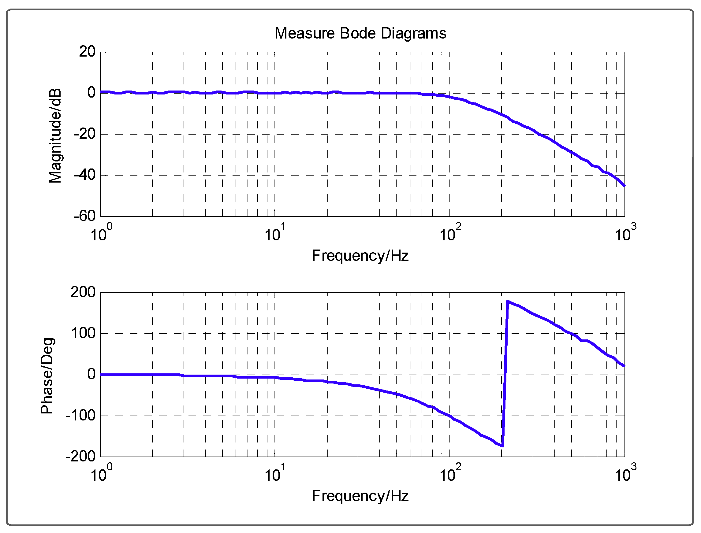
Before designing the closed-loop controller, the model of the platform should be acquired with a spectrum fitting method. In order to identify the parameters in Equation (19), the driver should output a sinusoidal signal of varying frequency to actuate the Tracking FSM. Then the FOG would be used to detect the motion state; comparing the output to the input, the open-loop bode response of the velocity can be drawn with the blue line, as shown in Figure 10. Finally, the parameters were adjusted to make the red curve of the model coincide with the blue one, and a high-precision transfer function could be acquired, as shown in Equation (24).
G ˜ v ( s ) = 2.3 s 0.00072 s 2 + 0.0202 s + 1 1 0.0005 s + 1  
The closed-loop bode response of the velocity was exhibited in Figure 11, in which the bandwidth passed 100 Hz, and the resonance peak of the open-loop velocity model under 7 Hz was eliminated, benefiting the controller design of the outer position loop. Below 10 Hz, the amplitude was close to 0 dB and the phase loss was less than 6 , which indicated that the closed-loop transfer function could be regarded as 1 in this low frequency band. Therefore, it was enough to take a proportional link as the position controller.

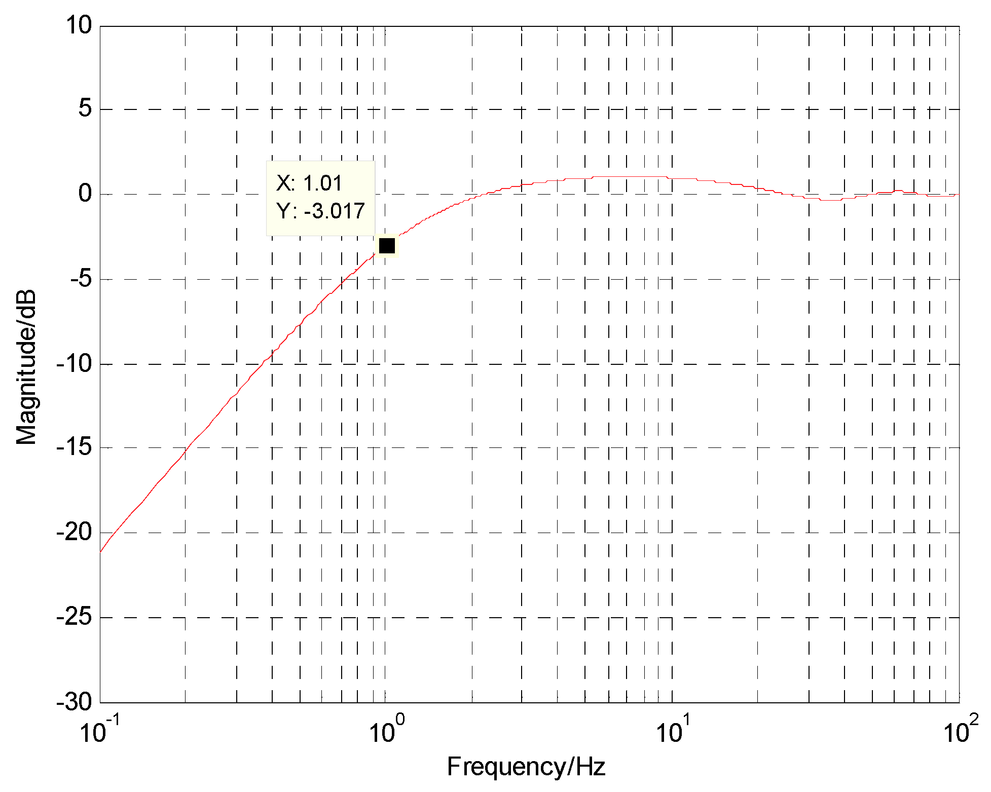
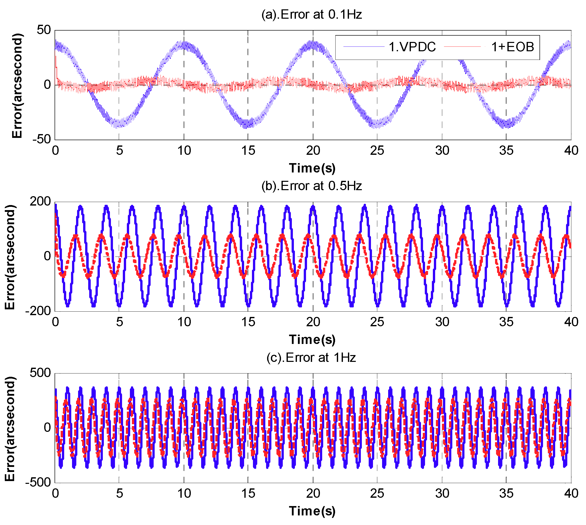
5.1. The Improvement of the TP with EOB
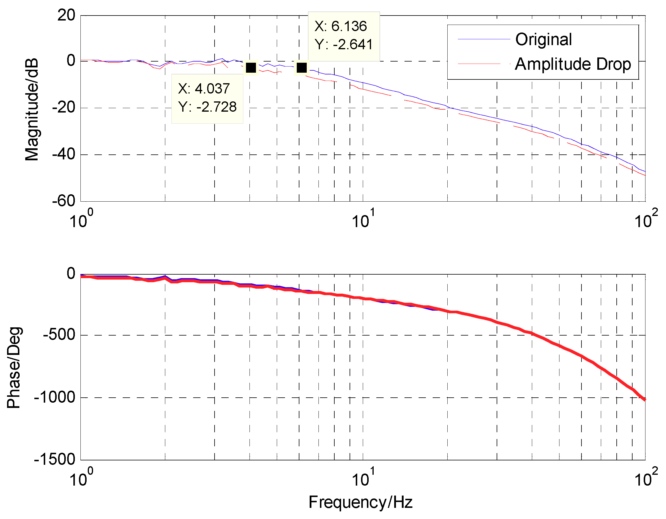
In Figure 12, the closed-loop bode responses of the position with or without EOB were described. When the EOB was introduced, the amplitude of the position controller should drop a little to guarantee enough margins. Although the bandwidth of the system with EOB was decreased by about 2 Hz, it would make no difference, because the performance below 1 Hz was adopted for tracking.
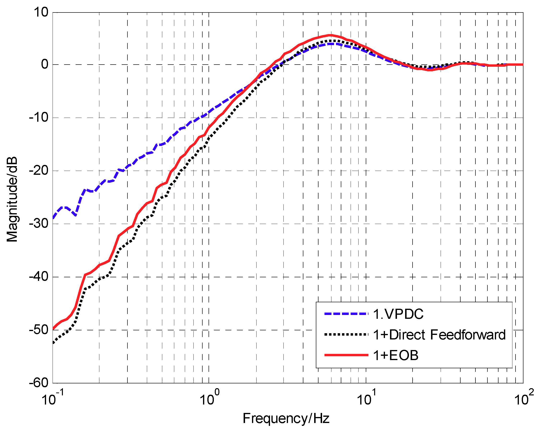
The error suppression bode response of the MTOS was presented in Figure 13, which only provided the target signal. Three methods were listed overall, the basic VPDC method, the direct feedforward method and the EBO method based on the VPDC. Obviously, the direct feedforward method based on sensors fusion with the predictive way had the best error suppression performance. However, the performance of the EBO method was close to the direct feedforward, which signified that the previous analysis was right and the proposed way was approximately equivalent to the direct feedforward method. Moreover, compared with the direct feedforward, the EBO method did not need an additional position sensor to measure the angular of the platform and cost a smaller amount of computation. Below 2 Hz, the system with EOB would have a better ability of error suppression than the pure VPDC without EOB; actually, it would be valid for both tracking and anti-disturbance. With the decrease of the frequency, the promotion of ability would be more apparent and could even reach −20 dB under 0.1 Hz. In the frequency band between 2 Hz and 18 Hz, the performance of the pure VPDC was a little better than the system with EBO, as shown in Figure 7, and the performance could be accepted. In Figure 14, the time-domain residual error was presented with the given target signal of different frequencies. In the frequency domain below 1 Hz, the EBO can make a big difference.

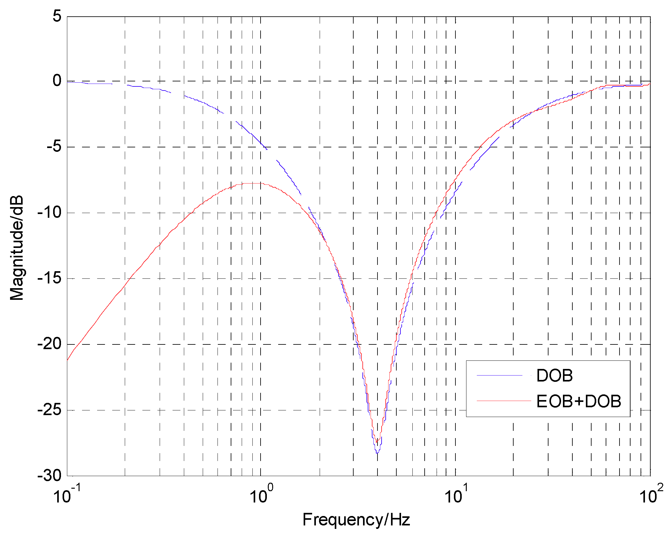
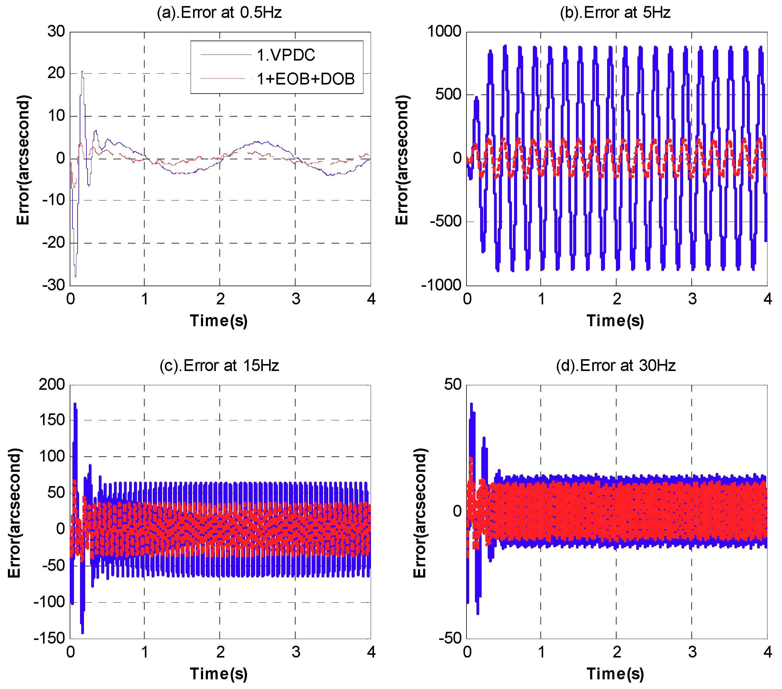
5.2. The Improvement of the ADA with the Combination of EOB and DOB

According to Equation (22), the DOB controller Q 2 is not the ideal value and a concession should be made. Parameter b can determine the starting point of disturbance compensation. Considering that the used FOG in this experiment had a poor performance below about 1 Hz, the actually used Q 2 was set as Equation (25) and all the parameters of controllers were listed in Table 1.
Q 2 = 0.00072 s 2 + 0.0202 s + 1 2.3 ( s + 5 ) 1 0.0065 s + 1  
The disturbance suppression bode response is presented in Figure 15, which involved four situations in all, showing the pure VPDC structure and the various combinations of EOB and DOB based on VPDC; the VPDC without any feedforward had a relatively poor ADA, especially in the middle frequency domain of about 5 Hz, which approached 0 dB. The EOB has apparently promoted the ADA of the low frequency below 1 Hz, sometimes (for example, on a ship) there would be a shake of carrier with a strong amplitude. The reason why the promotion was restricted at the frequency of 0.1 Hz was that the performance of the system almost reached the limitation under this noise condition. The DOB mainly worked at the medium frequency, where there was a maximum increase of −20 dB, because the measured signals and the reference model were relatively more accurate in this band. With the simultaneous help of EOB and DOB, the ADA had an improvement (at least −10 dB) in both the low and medium frequencies, which means that the system’s precision would nearly be increased by an order of magnitude. The proposed method could not enhance the very high-frequency ADA, which mainly depended on the mechanical design. Figure 16 shows the time-domain residual error with a given disturbance signal of different frequencies. Obviously, with the proposed way, the residual error was reduced below 30 Hz.
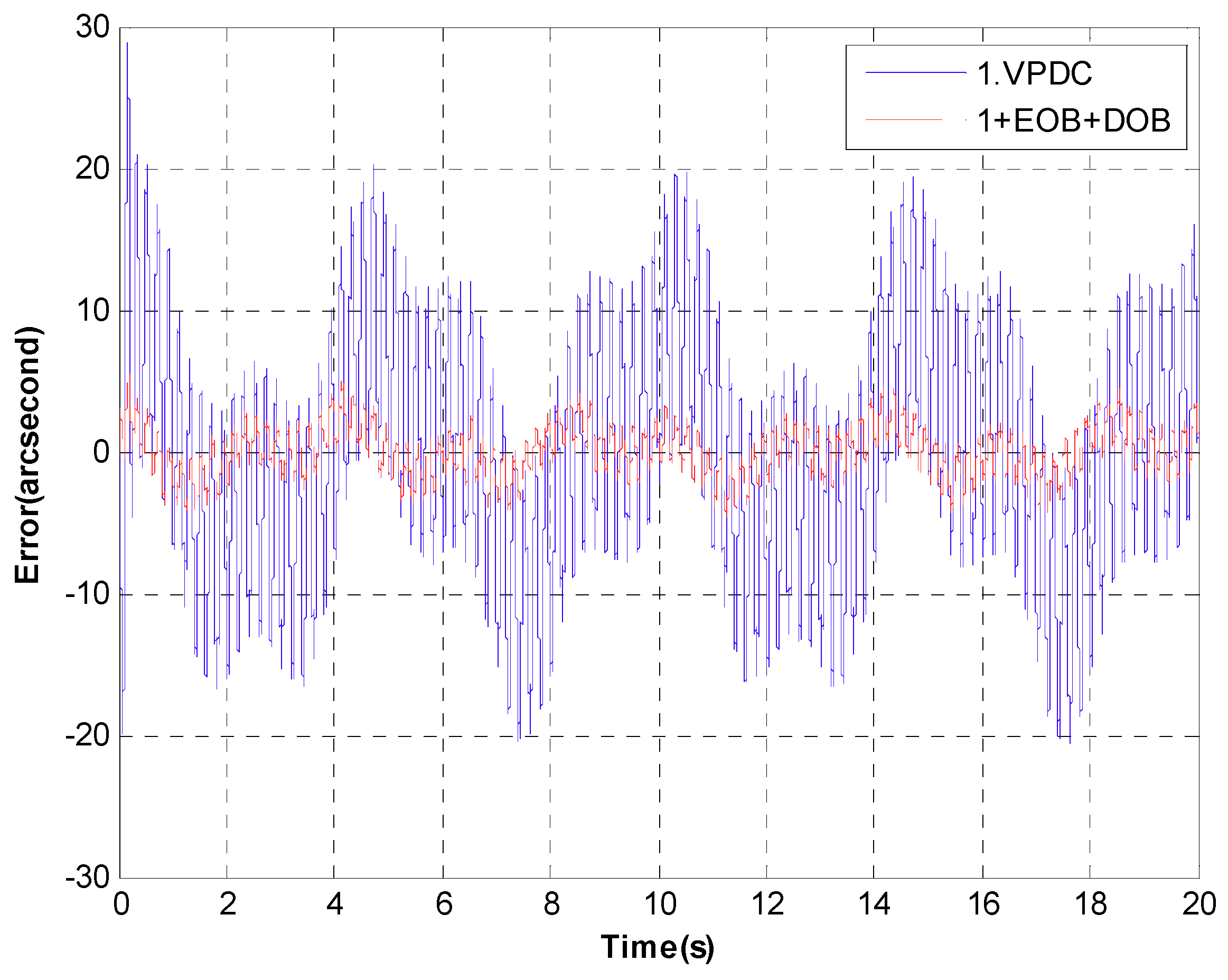
In order to verify the level of accuracy under the actual engineering conditions, we should detect the residual errors when simultaneously giving the target signal and disturbances to the system. In Figure 17, the results were presented and there was huge promotion. The target signal was 0.28° 0.2 Hz and the disturbances consisted of 0.28° 0.5 Hz, 0.0028° 5 Hz and 0.028° 50 Hz. The RMS error of the pure VPDC was 8.6504″ and the RMS error with additional EOB and DOB was 1.8111″, signifying that the proposed way of observation was valid.

6. Conclusions

In this paper, an unconventional feedforward method was introduced based on indirect measurement. EOB and DOB were combined to enhance the low-frequency TP and improve the ADA in a wide frequency band. The CCD and model output-based EOB were essentially a combination of the incomplete tracking and disturbance feedforward, which increases the low-frequency performance. The FOG-based DOB was a supplement for enhancing the relatively high-frequency ADA. The potential of the sensors was fully released and the low-bandwidth CCD and high-bandwidth FOG were made complementary. The multi-loop feedback control and feedforward control were simultaneously adopted to promote the accuracy and stability of the system. The design of Q 1 and Q 2 was analyzed, which is easy to be implemented in engineering. Experimental results demonstrated that a high-performance MOTS with a satisfied TP and strong ADA was acquired.
Since the performance of the system enhanced by the proposed method has approached to the limitation in this noise condition, we will consider regarding noise as an input and adopt some time-domain filters to decrease the impact of noise on the system.

Author Contributions

Conceptualization, Y.L., Y.H. and Y.M.; Data curation, Y.M.; Formal analysis, Y.L.; Funding acquisition, Y.M.; Investigation, W.R.; Methodology, Y.L. and Q.W.; Project administration, X.Z.; Resources, Y.H.; Software, W.R. and Q.H.; Supervision, Q.H.; Validation, X.Z.; Visualization, W.R.; Writing—original draft, Y.L.; Writing—review & editing, Y.L.

Funding

This research received no external funding.

Acknowledgments

We would extend our sincere gratitude to the Chinese Academy of Science for her sponsor.

Conflicts of Interest

The authors declared no conflict of interest.

Appendix A

To investigate L ( s ) , substitute e α s = cos ( α w ) j sin ( α ω ) into Equation (16),
L ( j ω ) = j ( k ω + T ω ) + 1 1 cos ( α ω ) + j [ T ω + sin ( α ω ) ]  
Because of the effect of the trigonometric functions, the phase function and magnitude function of L ( j ω ) will oscillate in each cycle. Assume ϕ ( ω ) is the phase of L ( j ω ) , and we could get
ϕ ( ω ) = a c   tan ( k ω + T ω ) a c   tan T ω + sin ( α ω ) 1 cos ( α ω )  
If α = 0 , we have ϕ ( ω ) = a c   tan ( k ω + T ω ) 0.5 π < 0 . Hence, T should be big enough to make the loss of phase small at ω c . Nevertheless, if T is too big, it will lead to the decreasing of the promotion for the system performance. Concentrating on the derivative function of ϕ ( ω ) as follows,
ϕ ( ω ) = k + T 1 + ( k + T ) 2 ω 2 ( T α ) [ 1 cos ( α ω ) ] T α ω sin ( α ω ) [ 1 cos ( α ω ) ] 2 + [ T ω + sin ( α ω ) ] 2  
Obviously, if T < α , then ϕ ( ω ) > 0 when T ω ( 0 ,   π 4 ) . However, since α (the CCD’s delay) cannot be too small, commonly, T has to be much bigger than α or it will result in instability. Actually, when T > α and T ω ( 0 ,   π 4 ) , we can still get ϕ ( ω ) > 0 .
Proof. 
T ω ( 0 ,   π 4 ) .
Define ψ ( ω ) = ( T α ) [ 1 cos ( α ω ) ] T α ω sin ( α ω ) .
If ψ ( ω ) < 0 , obviously, ϕ ( ω ) > 0 .
Since ψ ( 0 ) = 0 and ψ ( ω ) = α 2 [ sin ( α ω ) + T ω cos ( α ω ) ] < 0 , we get ψ ( ω ) < 0 . Then, ϕ ( ω ) > 0 .
From the above discussion, ϕ ( ω ) is always increasing when ω is from 0 to π 4 τ . Note that
{ ϕ ( 0 ) = 0.5 π ϕ ( ω c ) = a c   tan ( 1 + T ω c ) a c   tan T ω c + 2 / 2 1 2 / 2 < 0  
It means that no matter what T is, the phase loss is inevitable. If we consider the amplitude of L ( j ω ) , the same result will be obtained. The gain function of L ( j ω ) is as follows.
20 log | L ( j ω ) | = 10 log [ ( k ω + T ω ) 2 + 1 [ 1 cos ( α ω ) ] 2 + [ T ω + sin ( α ω ) ] 2 ]  
It is obvious that 20 log | L ( j ) | = 20 log ( k T + 1 ) , T > > k is hoped for reducing the sacrificing of GM. But,
20 log | L ( j ω g ) | = 10 log [ 1 + 4 T ω g + 1 4 + T 2 ω g 2 ] < 0  
From Equation (A6), it can be concluded that the GM will also suffer losses. □

References

  1. Cochran, R.W.; Vassar, R.H. Fast-Steering Mirrors in Optical Control Systems. In Advances in Optical Structure Systems, Proceedings of the SPIE 1303, Orlando, FL, USA, 16–20 April 1990; SPIE: Bellingham, WA, USA, 1990. [Google Scholar]
  2. Shlomi, A.; Kopeika, N.S. Vibration noise control in laser satellite communication. Proc. SPIE 2001, 4365, 188–194. [Google Scholar]
  3. Liu, W.; Yao, K.; Huang, D.; Lin, X.; Wang, L.; Lv, Y. Performance evaluation of coherent free space optical communications with a double-stage fast-steering-mirror adaptive optics system depending on the Greenwood frequency. Opt. Express 2016, 24, 13288–13302. [Google Scholar] [CrossRef] [PubMed]
  4. Leven, W.F.; Lanterman, A.D. Unscented kalman filters for multiple target tracking with symmetric measurement equations. IEEE Trans. Autom. Control 2009, 54, 370–375. [Google Scholar] [CrossRef]
  5. Cao, Y.; Wang, G.; Yan, D.; Zhao, Z. Two algorithms for the detection and tracking of moving vehicle targets in aerial infrared image sequences. Remote Sens. 2015, 8, 28. [Google Scholar] [CrossRef]
  6. Ekstrand, B. Tracking filters and models for seeker applications. IEEE Trans. Aerosp. Electron. Syst. 2001, 37, 965–977. [Google Scholar] [CrossRef]
  7. Tang, T.; Huang, Y.; Liu, S. Acceleration feedback of a CCD-based tracking loop for fast steering mirror. Opt. Eng. 2009, 48, 510–520. [Google Scholar]
  8. Yeung, K.S.; Wong, W.T. Root-locus plot of systems with time delay. Electron. Lett. 1982, 18, 480–481. [Google Scholar] [CrossRef]
  9. Engelborghs, K.; Dambrine, M.; Roose, D. Limitations of a class of stabilization methods for delay systems. IEEE Trans. Autom. Control 2001, 46, 336–339. [Google Scholar] [CrossRef]
  10. Srivastava, S.; Pandit, V.S. A PI/PID controller for time delay systems with desired closed loop time response and guaranteed gain and phase margins. J. Process Control 2016, 37, 70–77. [Google Scholar] [CrossRef]
  11. Tang, T.; Ma, J.; Ge, R. PID-I controller of charge coupled device-based tracking loop for fast-steering mirror. Opt. Eng. 2011, 50, 043002. [Google Scholar] [CrossRef]
  12. Cao, Z.; Chen, J.; Deng, C.; Mao, Y.; Li, Z. Improved Smith predictor control for fast steering mirror system. IOP Conf. Ser. Earth Environ. Sci. 2017, 69, 012085. [Google Scholar] [CrossRef] [Green Version]
  13. Ren, W.; Luo, Y.; He, Q.N.; Zhou, X.; Deng, C.; Mao, Y.; Ren, G. Stabilization Control of Electro-Optical Tracking System with Fiber-Optic Gyroscope Based on Modified Smith Predictor Control Scheme. IEEE Sens. J. 2018, 18, 8172–8178. [Google Scholar] [CrossRef]
  14. Jing, T.; Yang, W.; Peng, Z.; Tao, T.; Li, Z. Application of MEMS Accelerometers and Gyroscopes in Fast Steering Mirror Control Systems. Sensors 2016, 16, 440. [Google Scholar]
  15. Dickson, W.C.; Yee, T.K.; Coward, J.F.; Mcclaren, A.; Pechner, D.A. Compact Fiber Optic Gyroscopes for Platform Stabilization; SPIE: San Diego, CA, USA, 2013; pp. 7453–7458. [Google Scholar]
  16. Yoon, Y.G.; Lee, S.M.; Kim, J.H. Implementation of a Low-cost Fiber Optic Gyroscope for a Line-of-Sight Stabilization System. J. Inst. Control 2015, 21, 168–172. [Google Scholar]
  17. Tang, T.; Huang, Y. Combined line-of-sight error and angular position to generate feedforward control for a charge-coupled device–based tracking loop. Opt. Eng. 2015, 54, 105107. [Google Scholar] [CrossRef] [Green Version]
  18. Xie, R.; Zhang, T.; Li, J.; Dai, M. Compensating Unknown Time-Varying Delay in Opto-Electronic Platform Tracking Servo System. Sensors 2017, 17, 1071. [Google Scholar] [CrossRef] [PubMed]
  19. Böhm, M.; Pott, J.U.; Kürster, M.; Sawodny, O.; Defrère, D.; Hinz, P. Delay Compensation for Real Time Disturbance Estimation at Extremely Large Telescopes. IEEE Trans. Control Syst. Technol. 2016, 25, 1384–1393. [Google Scholar] [CrossRef]
  20. Glück, M.; Pott, J.U.; Sawodny, O. Piezo-actuated vibration disturbance mirror for investigating accelerometer-based tip-tilt reconstruction in large telescopes. IFAC-PapersOnLine 2016, 49, 361–366. [Google Scholar] [CrossRef]
  21. Kim, B.K.; Wan, K.C. Advanced disturbance observer design for mechanical positioning systems. IEEE Trans. Ind. Electron. 2004, 50, 1207–1216. [Google Scholar]
  22. Luo, Y.; Huang, Y.; Deng, C.; Yao, M.; Ren, W.; Wu, Q. Combining a disturbance observer with triple-loop control based on MEMS accelerometers for line-of-sight stabilization. Sensors 2017, 17, 2648. [Google Scholar] [CrossRef] [PubMed]
Figure 1. Configuration of the MOTS.
Electronics 07 00223 g001
Figure 2. The VPDC structure. G v refers to the velocity open-loop transfer function. C v and C p respectively refer to the velocity controller and position controller. e τ s refers to the delay element of the CCD. E refers to the boresight error without delay. R and D respectively refer to the target signal and the external disturbance signal. Y refers to the corresponding movement of the boresight.
Electronics 07 00223 g002
Figure 3. The direct feedforward structure based on VPDC.
Electronics 07 00223 g003
Figure 4. The EOB structure based on VDPC. e a s refers to an artificially added delay and α = τ . Q 1 refers to the EOB controller.
Electronics 07 00223 g004
Figure 5. The equivalent structure of EOB. B v = C v G v / ( 1 + C v G v ) refers to the closed-loop transfer function. B v 1 at a low frequency.
Electronics 07 00223 g005
Figure 6. The VPDC structure enhanced by EOB and DOB. G ˜ v refers to the approximate velocity model of the platform and G ˜ v G v . Q 2 refers to the DOB controller.
Electronics 07 00223 g006
Figure 7. The simulation of the performance promotion with EBO.
Electronics 07 00223 g007
Figure 8. The simulation of the ADA improvement.
Electronics 07 00223 g008
Figure 9. Experimental setup.
Electronics 07 00223 g009
Figure 10. The open-loop bode response of the velocity.
Electronics 07 00223 g010
Figure 11. The closed-loop bode response of the velocity.
Electronics 07 00223 g011
Figure 12. The closed-loop bode responses of the position.
Electronics 07 00223 g012
Figure 13. The error suppression response of the MOTS.
Electronics 07 00223 g013
Figure 14. The residual tracking errors in different frequencies.
Electronics 07 00223 g014
Figure 15. The disturbance suppression response of the MOTS.
Electronics 07 00223 g015
Figure 16. The residual stabilization errors in different frequencies.
Electronics 07 00223 g016
Figure 17. The residual error with the given signals of the target and disturbances.
Electronics 07 00223 g017
Table 1. The parameters of controllers. When EOB is added, C p should be changed to C p = 0.8 C p for sufficient PM and GM according to the previous analysis.
Controllers C p C v Q 1 Q 2
Parameters π 4 τ = 39.25 k v = 16.8
T e = 0.0005
T v = 0.0003
ω n = 5.9 Hz
ξ = 0.3764
T = 0.12 K = 2.3
b = 5
T 1 = 0.0065
ω n = 5.9 Hz
ξ = 0.3764

