Article

Energy Management and Switching Control of PHEV Charging Stations in a Hybrid Smart Micro-Grid System

by
Tariq Kamal
1,2,*,
Murat Karabacak
2,
Syed Zulqadar Hassan
3,
Luis M. Fernández-Ramírez
1,
Muhammad Hussnain Riaz
4,
Muhammad Tanveer Riaz
3,
Muhammad Abbas Khan
5 and
Laiq Khan
6
1
Research Group in Electrical Technologies for Sustainable and Renewable Energy (PAIDI-TEP-023), Department of Electrical Engineering, University of Cadiz, Higher Polytechnic School of Algeciras, 11202 Algeciras (Cadiz), Spain
2
Department of Electrical and Electronics Engineering, Sakarya University, 54050 Sakarya, Turkey
3
State Key Laboratory of Power Transmission Equipment and System Security and New Technology, School of Electrical Engineering, Chongqing University, 400044 Chongqing, China
4
Department of Electrical Engineering, Lahore University of Management Sciences (LUMS), 54792 Lahore, Pakistan
5
School of Electronics and Information Engineering, Changchun University of Science and Technology, Jilin 130022, China
6
Department of Electrical Engineering, COMSATS Institute of Information Technology, 22060 Abbottabad, Pakistan
*
Author to whom correspondence should be addressed.
Electronics 2018, 7(9), 156; https://doi.org/10.3390/electronics7090156
Submission received: 30 June 2018 / Revised: 13 August 2018 / Accepted: 20 August 2018 / Published: 22 August 2018
(This article belongs to the Special Issue Applications of Power Electronics)

Abstract

:
In this study, the energy management and switching control of plug-in hybrid electric vehicles (PHEVs) in a hybrid smart micro-grid system was designed. The charging station in this research consists of real market PHEVs of different companies with different sizes. The rate of charging of PHEVs is managed via switching control to receive maximum benefits from renewable energy sources and reduce the consumption of electricity from the grid. To support the optimum utilization of sustainable power, charging time and network stability, seven scenarios were developed for different interaction among the proposed micro-grid system and PHEVs. The proposed hybrid smart micro-grid system consists of three renewable energy sources: photovoltaic (PV) array controlled via an intelligent fuzzy control maximum power point subsystem, a fuel cell stack and a microturbine set controlled by proportional integral differential/proportional integral subsystems. A hybrid energy storage system (super-capacitor, battery storage bank and hydrogen) and residential load are also included in the proposed architecture. The hybrid smart micro-grid system is checked in terms of voltage regulation, frequency deviation and total harmonic distortion (THD). It was found that these are in limits according to the international standards. The simulations verify the feasibility of the proposed system and fulfill the requirement of vehicle-to-grid and grid-to-vehicle operations in a smart grid environment.

1. Introduction

Due to environmental concerns, depletion of fossil fuels, and advances in battery storage system, PHEVs have received a great amount of attention in the transportation sector [1,2]. These days, the world is looking towards renewable energy sources such as solar, wind and biomass to produce green energy. This green energy can be utilized by vehicles which are considered the main sources of environmental pollution. For example, 33.7% of greenhouse gas emissions were released by the transportation sector to the environment in 2012 [3]. Similarly, many American Lungs Association projects have stated [4] that the transportation sector is responsible for numerous lung diseases in America. Consequently, transport industries have introduced low emission vehicles such as PHEVs to directly address these problems. Therefore, each year, the purchase of PHEV increases worldwide. In the future, many Electric Vehicles (EVs) will be available in the transportation sector. For example, in 2015, approximately one million PHEVs were on US roads and 425,000 PHEVs were sold [5,6]. Furthermore, the Electric Power Research Institute have concluded that the PHEVs market share may reach up to 62% by 2050 in the US [7]. In the US, there are about 250 million registered vehicles. Using a moderate scenario since 2020, if the US vehicle fleet is 10% PHEVs and each vehicle uses 25 kWh battery capacity, the total 625 GWh would be a potential threat to today’s utility.
The first electric vehicle was sold in Turkey in 2012 [8]. The electric vehicle market in Turkey is now growing very rapidly. According to the Ministry of Science, Industry and Technology of Turkey, PHEVs will become the dominant vehicle choice on the road soon in Turkey. The increasing of PHEVs could burden the existing utility, which can result power losses at the customers end. Specifically, uncontrolled charging can cause grid stability problems on the local scale. Pakistan under Rahmat Group company has signed an agreement with two different Chinese companies to introduce EVs in Pakistan [9]. In the initial stage, the companies will introduce electric buses in the transport market, and in the second phase, a factory would be established at the complex in Jamshoro District of Sindh, Pakistan to produce electric cars and two-wheelers. According to the Energy Conservation Center belonging to the Ministry of Water and Power of Pakistan, the transport sector represents 28% of the total energy consumption in Pakistan. In the Pakistan scenario reported on 30 June 2015, the gap between electricity demand and supply was 5201 MW [10]. Currently, Pakistan is suffering from severe energy crisis, where urban and rural areas are not powered by proper electricity for 8–12 h and 18 h per day, respectively. There is a growing risk that the proliferation of EVs will trigger extreme surges in demand in Pakistan. This cannot be ignored, especially in Pakistan, and therefore, it is imperative to design a Charging Station (CS) setup powered from Renewable Energy Sources (RESs) coupled with smart charging strategies.
Generally, vehicles are supposed to stay for at least 5 h per day in workplace [11]. Hence, making electric CS in a given workplace is beneficial, but the result would be some overloading issues particularly at the distribution level. Since the upgrading of transformer is an inflexible and a quite expensive option, this concern needs close concentration. Many authors in the literature have studied the effect of PHEVs charging on the distribution transformer [12,13,14]. In [12], the authors discussed the impact of PHEVs on distribution networks, but there is no analytical calculation in the paper. In [13], the authors analyzed the concerns due to the integration of PHEV on the residential distribution networks; however, in this study, the number of PHEVs per distribution transformer was limited to two. The authors concluded in [14] that the power management of the EV battery charge profile can help manage the loss of life of the distribution transformer. However, not much work has been done to charge the PHEVs from several RESs in a smart micro-grid.
Although there are a few published papers about CSs for PHEV supplied by PV [15,16,17,18], they present certain limitations. For instance, the control of the PV system was not studied in [15,16,17,18]. Further, in all these papers, the authors designed the CSs based on the control of DC-link voltage, but the DC-link voltage has its own limitation and the authors did not consider the control of DC-link voltage when it reaches its maximum limit. Similarly, several authors focused on the residential distribution networks [19,20,21]. In [22,23], the authors described the overall peak demand due to the charging of EVs. They suggested that it should be managed effectively with proper load management. Smart control strategies that can open the paths for PV systems and EVs to integrate with the current power systems are suggested in [24]. The charging of PHEVs from PV system and its co-benefits are discussed in [25]. The study explains that PV provides an auspicious source of mid-day generation power for PHEVs while PHEVs perform as a dispatchable load. In another paper, the authors showed that high scale integration of EVs in the existing utility would be possible through management and scheduling [26]. The significance of EVs operating as an energy storage source is studied in [27]. There are three types of charging methods for PHEVs/EVs: Alternating Current (AC) level-1, AC level-2 and Direct Current (DC) level-3 charging. DC charging allows boosting the overall efficiency and providing the opportunity of fast charging [28,29,30]. The same concept is also supported in [31,32]. This sets it up appropriately to mix distributed renewable power generations such as PV, fuel cells, wind and other energy storage devices such as super-capacitor (SC) using the DC distribution bus (bus is an electrical node, which can be in DC or AC, where two or more electrical elements, such as loads, generators, etc., meet). Different DC charging station infrastructures have been presented by many authors [33,34].
The integration of PHEVs in municipal parking deck using smart energy management system is developed in [35]. The energy management system is there to control provision of energy to the vehicle battery chargers through real time monitoring to secure the maximum consumption of available power from sustainable energy and charging time. None of the papers reviewed provide an intelligent control, power electronics interface and power management of PHEVs in smart micro-grid system, where the primary energy source is controlled efficiently. None of those reviewed studies consider the real weather characteristics, but many researchers have developed charging station using virtual generated weather patterns. Moreover, the intelligent control of a renewable energy source is very important for a stable DC bus voltage. For instance, fluctuations in bus voltage cause power imbalance that originate from different sources of disturbances such as sudden change in solar irradiance or temperature, and abrupt change in PHEVs load. Such a power imbalance results an extra energy. The above-mentioned papers do not discuss the control of photovoltaic in their charging station which is essential for maximum efficiency.
This paper intends a proper power management for different PHEV models in a hybrid smart micro-grid system where the required power for the PHEVs charging is smartly managed from solar, hydrogen energy (fuel cell), natural gas (micro-turbine), SC, battery and grid. The operation of the charging algorithm is performed using dynamic power switches of the power converters controlled via proportional integral differential/proportional integral subsystems. The highly intermittent nature of PV in the proposed hybrid smart micro-grid system is addressed by an isolated intelligent fuzzy inference subsystem. The intelligent fuzzy inference subsystem contributes to minimize the stress on the DC bus and ensures quality and regulated output power to CS. If the power sent by the PV is in excess of the requirement of the PHEVs charging, the remaining power will be supplied to charge the battery and then the SC. If still there is an excess power, then it will be used to produce hydrogen for fuel cell or sent to a national grid. Correspondingly, if the net power provided by the PV is less than the demand, the battery and then the SC will be used to deliver the required power provided their SoC > 20%. If the requirement surpasses the power provided by the combination of PV/SC/battery, the difference is provided by the fuel cell. If there is still a need, the difference will be covered by the Micro-turbine (MT), followed by the national grid. In addition, the proposed CS also comprises of a Battery Storage System (BSS) as supplementary power sources to store the power in off peak hours, which can be used in rush hours to charge the PHEVs or provide to the grid.
This work is arranged as follows: Section 2 gives the description of the proposed hybrid smart micro-grid system. The control of the systems components is described in Section 3. The problem formulation of the proposed work is presented in Section 4. Section 5 deals with the proposed power management. Section 6 supports the performance of the proposed system via simulations, followed by a conclusion in Section 7.

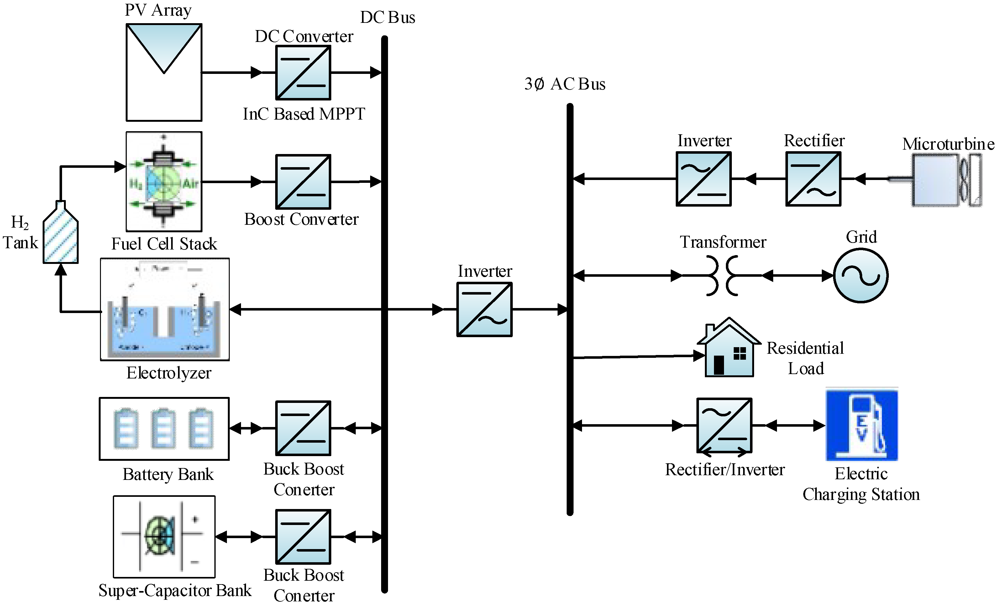
2. System Description

Figure 1 shows the proposed system configuration combining PV system, FC system, SC module and battery bank to form a combine DC bus line by four different non-isolated DC-DC converters. The PV system is taken as the primary power source; SC module and battery bank serves as a short-term storage system; and the Solid Oxide Fuel Cell (SOFC) is used as a backup and long-term storage system [36]. The additional power with respect to the load requirement is used for the battery, SC charging and hydrogen production for later use in the SOFC. The output of the DC bus link is combined through a three-phase main inverter to supply the desired power to the grid if only one source is accessible. On the other hand, the PHEVs/EVs CS, MT, residential load and utility grid are integrated to form an AC bus line. The MT also behaves as a backup to take full advantage of RESs, while the CS acts as either load under the Grid-to-Vehicle (G2V) concept or distributed sources of energy under the Vehicle-to-Grid (V2G) revenue opportunity [37]. The MT interface consists of a rectifier followed by a unidirectional hysteresis current control inverter. A bidirectional inverter is used for power sending and receiving from the CS towards an AC bus link. The CS is designed to charge five PHEVs and BSS. The PHEVs are selected from five different companies. The grid attachment is used to accomplish any charging demand more than the RESs output. The development of all energy sources are according to Table 1 and taken from [38,39,40,41,42].

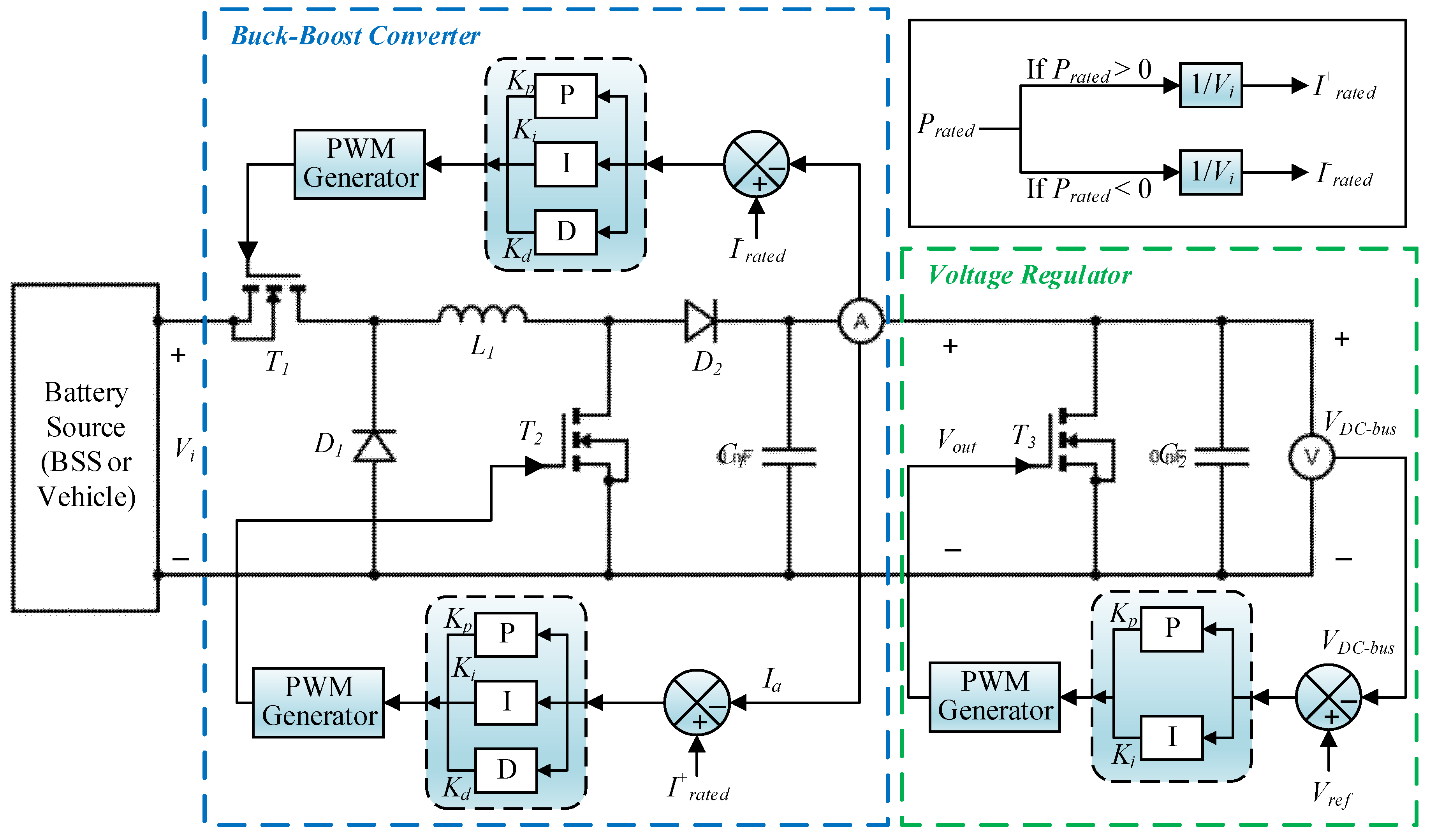
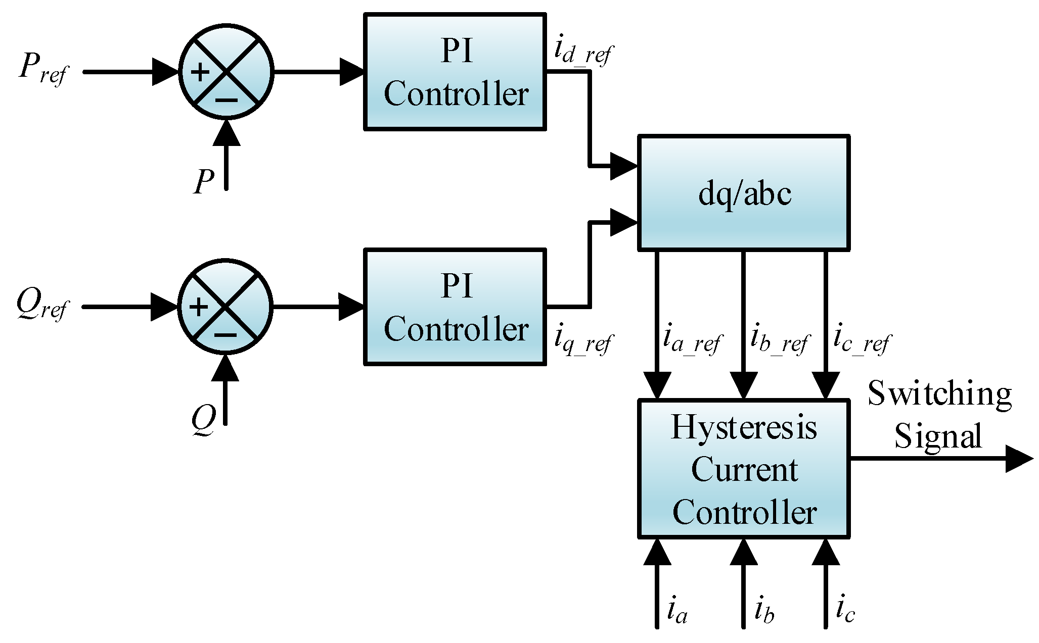
3. Architecture and Control of the Proposed Charging Station

Figure 2 illustrates a detailed structure of the proposed CS, which is located in Pakistan. The major components of CS are the PHEVs, BSS, power converters and the power management controller. A Power Management System (PMS) monitors all the PHEVs and BSS. The algorithm implemented in the PMS senses the State of Charge (SOC), rated charging power of the PHEVs batteries, the peak and off-peak hours, and controls the power flow in the CS, as given in Figure 2. The SoC level provides information about the charging and discharging of the PHEVs/EVs and BSS.
The PMS also consists of a Battery Management System (BMS) which prevents the PHEVs and BSS from getting overcharged. The BSS also supports the charging of the PHEVs when there is no power available from the AC bus link. The battery bank in the BSS can be charged from the AC bus link during off peak hours.
Five different types of PHEVs/EVs are considered: Mitsubishi i-MiEV, Kangoo Z.E, Toyota Prius plug-in, Nissan leaf, Honda Accord Hybrid and Renault. Their respective usable battery capacity and charging information is listed in Table 2. Since the PHEVs/EVs are from different automobile manufacturers, their control approach and BSS are based on the charging requirements of each PHEV and BSS. Each PHEV and BSS must have an autonomous buck-boost converter fitted in each charge point in the proposed CS. All the buck-boost converters of the CS are controlled by conventional Proportional Integral Differential (PID) controllers, as shown in Figure 3, and their parameters are given in Table 3.
The output of the overall charging station is coupled to the AC bus via a bidirectional inverter-controlled hysteresis current control embedded with PI controllers, as illustrated in Figure 4, whose parameters are shown in Table 1. The PI controllers try to reduce the error to adjust the desired active and the reactive powers. It is assumed that all vehicles have equal market penetration and the analysis is considered for a 24-h cycle for a typical summer day in Pakistan. The proposed architecture is flexible and multiple PHEVs can be charged by increasing the corresponding charging points. Furthermore, the DC-DC boost converter based on the intelligent fuzzy controller is used to exactly track the MPP of the PV, as shown in Figure 5. The intelligent fuzzy controller is modeled using expert knowledge and many inputs. Based on those inputs, the fuzzy rules are defined in the Fuzzy Logic Controller (FLC). A FLC operates in three steps: a fuzzifier to express the crisp value of inputs into their respective fuzzy sets, an inference system to generate appropriate output also in the form of fuzzy sets, and a De-fuzzifier to give the original crisp value through conversion theorems (i.e., center of area). Similarly, a DC-DC boost converter based on PI control is used to control the FC voltage.

4. Problem Formulation

In this paper, the objective is to design a decision-making control algorithm for the PHEVs CS by using the available resources (renewable energy, utility grid) for the PHEVs charging, while reducing the stress on the utility grid and satisfying the required demand of all PHEVs and BSS. Equation (1) represents the formulation for the PHEVs CS. According to Equation (1), the actual power level of all vehicles and BSS must reach their reference level within the desired time provided the charging constraints of all PHEVs/EVs and BSS according to Table 2. The power quality and network constraints are according to international standards such as IEC61000 and IEEE 519-2014. Pakistan’s LV power network is considered in this work.
[ P H E V i = 5 B S S ] | t [ P P H E V i = 5 (t ) P PHE V i=5 _ref ( t ) P BSS ( t ) P BSS _ref ( t ) ] s . t : SO C i , min S O C i ( t ) S O C i , max 0 | S O C ( t + 1 ) S O C ( t ) | | Δ S O C i , max V min l o a d ( rm s ) V load (rms) V maxload (rms) T H D min v load TH D v st ,TH D min i load TH D i st f minVfund < f Vload < f maxVfund
where SOCi,min and SOCi,max are the user-defined minimum and maximum battery SOCs limits for the ith PHEV/EV. Once SOCi reaches SOCi,max, the ith battery charger switches to a stand-by mode to avoid the overcharging of the PHEV/EV battery. To prevent large variations in the charging rate over consecutive time slots, the SoC ramp rate is bounded by the constraint ∆SOCmax. Vloadrms is the RMS voltage at the customer side; T H D v s t and T H D i s t are the acceptable value of total harmonic distortion in voltage and current, respectively; and fmin-vfund and fmax-vfund are the allowable limits in the load voltage frequency deviation.

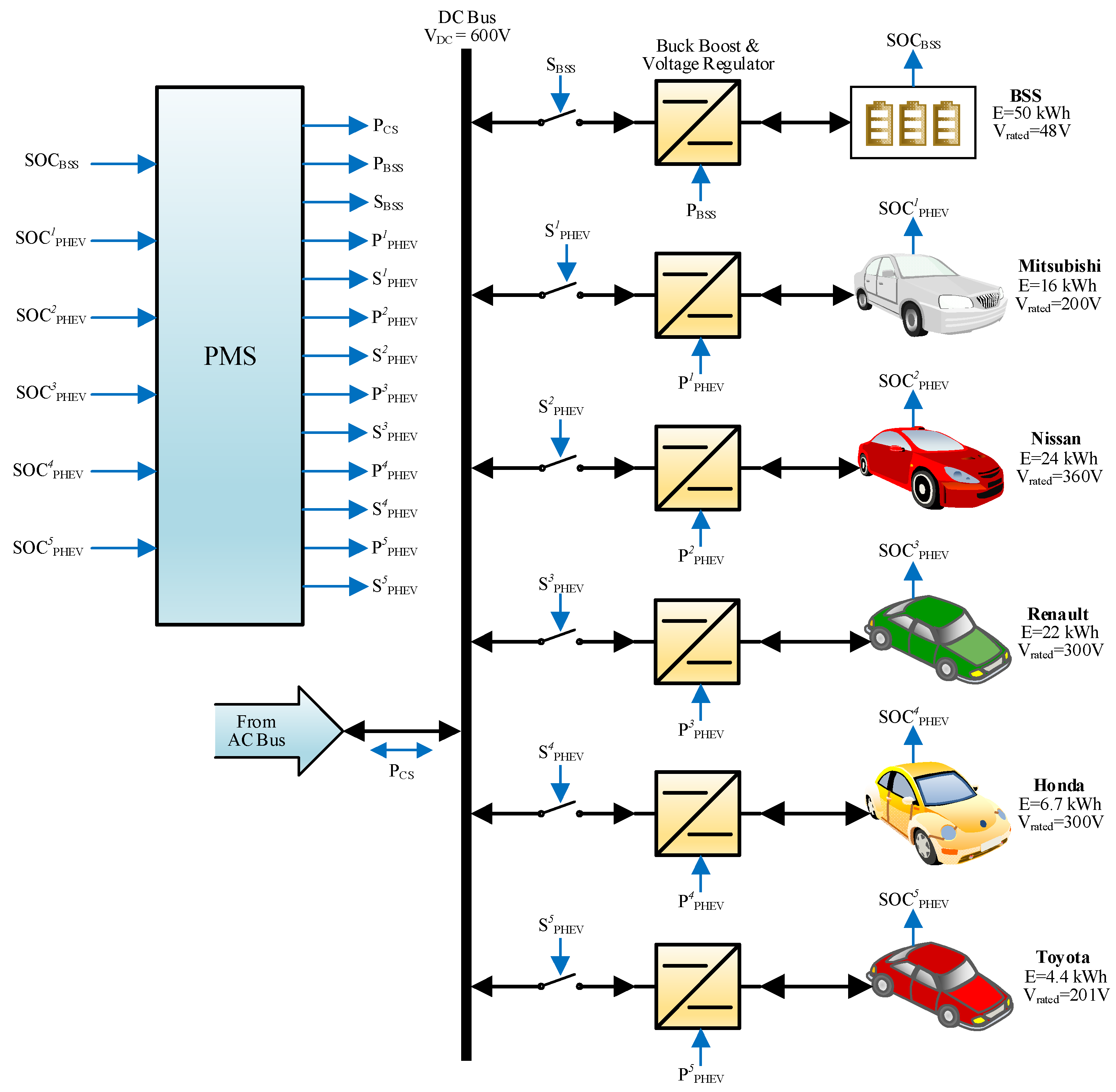
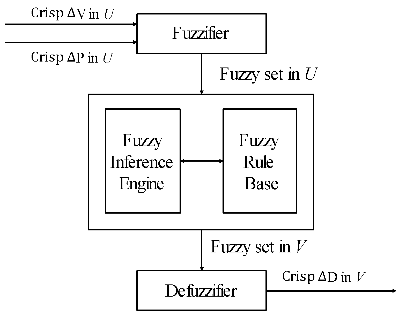
5. Proposed Power Management System for PHEVS/EVs

There are two main buses: DC and AC bus. The PHEVs/EVs CS is the major part of the AC bus. Therefore, the bidirectional power flow between the CSs and the rest of the system, especially with the grid, occurs via AC bus. The overall PMS consists of seven possible scenarios considered for a 24-h cycle as depicted in Figure 6. Five PHEVS/EVs and BSS are the main actors which take part in the PMS. Before explaining the PMS, one must know the following points which are considered during the simulation.
  • For the PHEVs charging, the PMS must to take power from BSS rather than the AC bus.
  • Similarly, in the case of discharging of PHEVs, first BSS then the AC bus is used to take power from the PHEVs.
  • The PHEV owner will decide how much power he wants to transfer or receive.

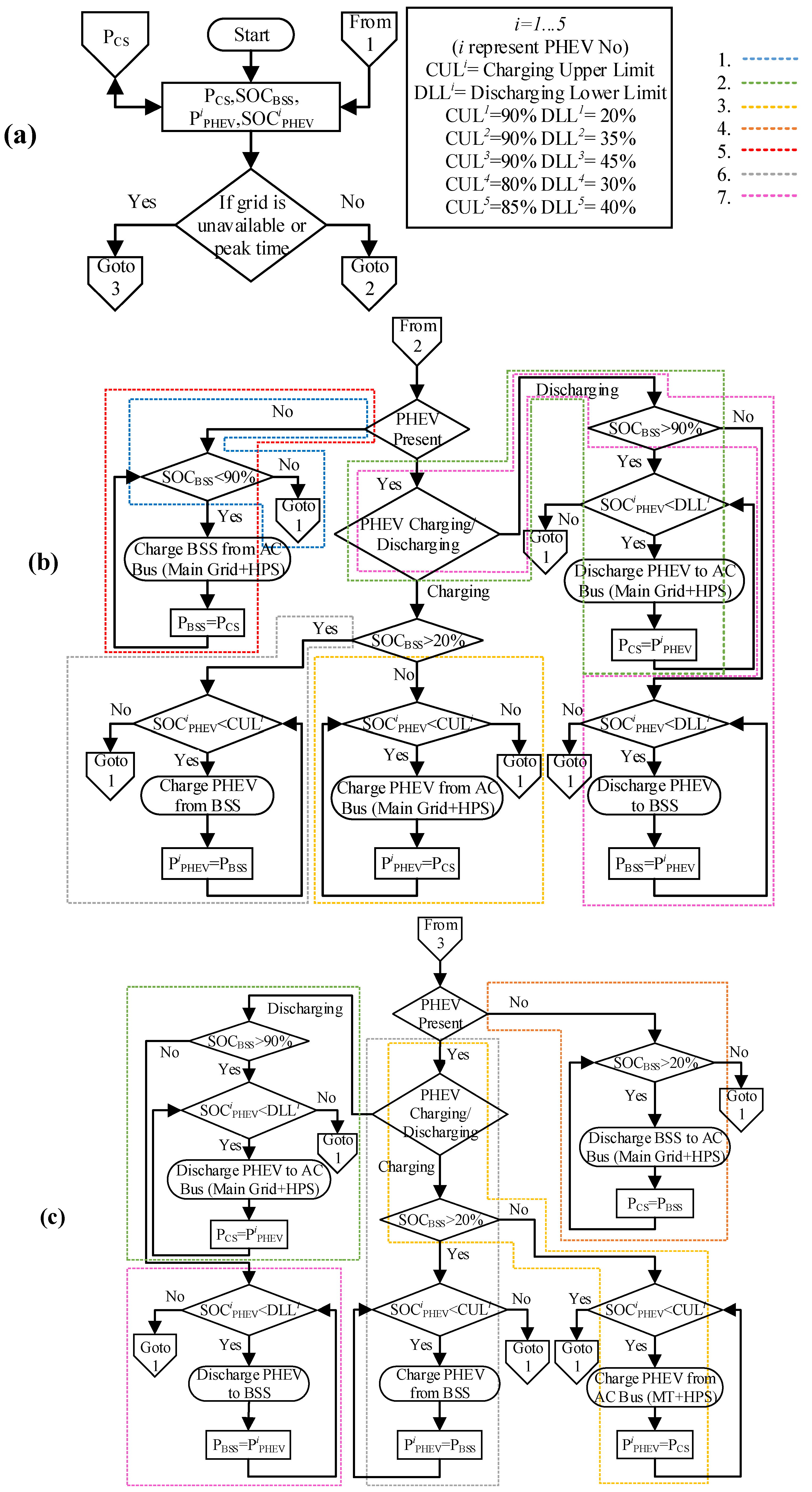
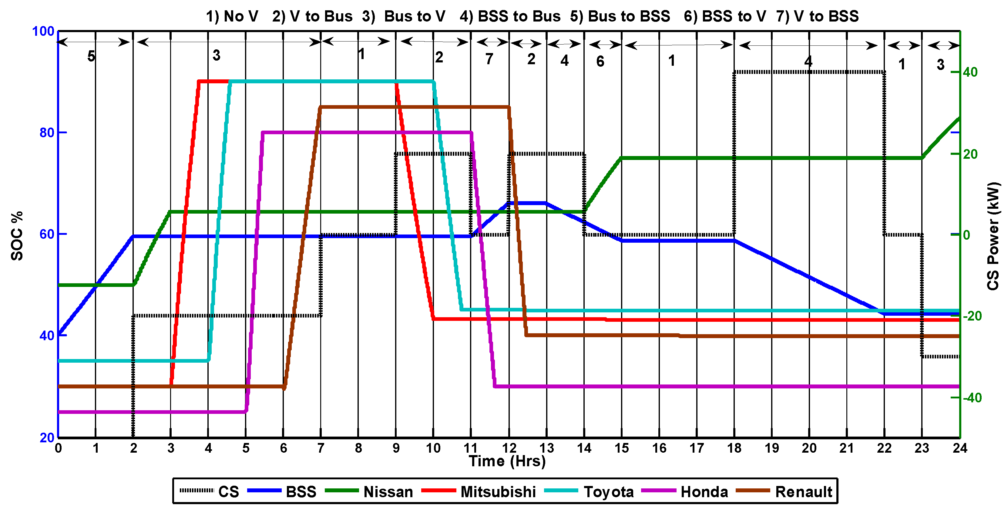
5.1. Proposed Scenarios for the Charging Station PMS

To develop a proper power management at a CS, several possible scenarios are taken for one complete day depending on the user preference and interest, as shown in Table 4. In a real-time scenario, the power flow between grid and PHEVs depend upon the mutual understanding between them.

5.1.1. Scenario 1 (No Cars in the CS or Empty CS)

This scenario was considered the normal situation. PHEVs are not present in the CS for charging and BSS is fully charged.

5.1.2. Scenario 2 (Vehicles to AC Bus Line)

This case is the most likely and creates a promising opportunity in the form of V2G or Vehicle-to-Home (V2H). In this scenario, the PMS first checks the availability of the charged PHEVs and the BSS. If the charged PHEVs are available and are programmed to discharge their power and the SoC of BSS is also greater than 90%, then the controller will allow the PHEVs to discharge to the AC bus. This power is further transmitted to the grid or to the load. The owners of the PHEVs will decide how much they discharge their PHEVs, which is automatically accomplished by the controller.

5.1.3. Scenario 3 (AC Bus to Vehicles)

In this situation, the controller first checks the SoC of the BSS. If the BSS is not available for PHEV charging, then the AC bus power is used to charge the PHEVs. It is imperative to show that the maximum power for the AC bus comes from RESs.

5.1.4. Scenario 4 (BSS to AC Bus)

It is also possible that there are no PHEVs in the CS and BSS is charged. The PMS controller will allow the charged BSS to supply its power to the AC bus. Depending upon the choice, the power could be transmitted to the grid or directly to the residential load. Regardless, it will reduce the overall stress on the grid.

5.1.5. Scenario 5 (AC Bus to BSS)

This case is considered for the off-peak time. According to the proposed PMS, if there are no PHEVs and all other loads are satisfied, then the AC bus will supply power to the BSS. The charged BSS will reduce the burden on the grid during peak times.

5.1.6. Scenario 6 (BSS to Vehicles)

Those PHEVs that want to be charged from the BSS are covered in this mode. The proposed PMS will allow the charged BSS to satisfy the required demands of the PHEVs.

5.1.7. Scenario 7 (Vehicles to BSS)

In this case, the controller will allow the PHEV to transfer power to the BSS. All seven scenarios are explained well during simulation.

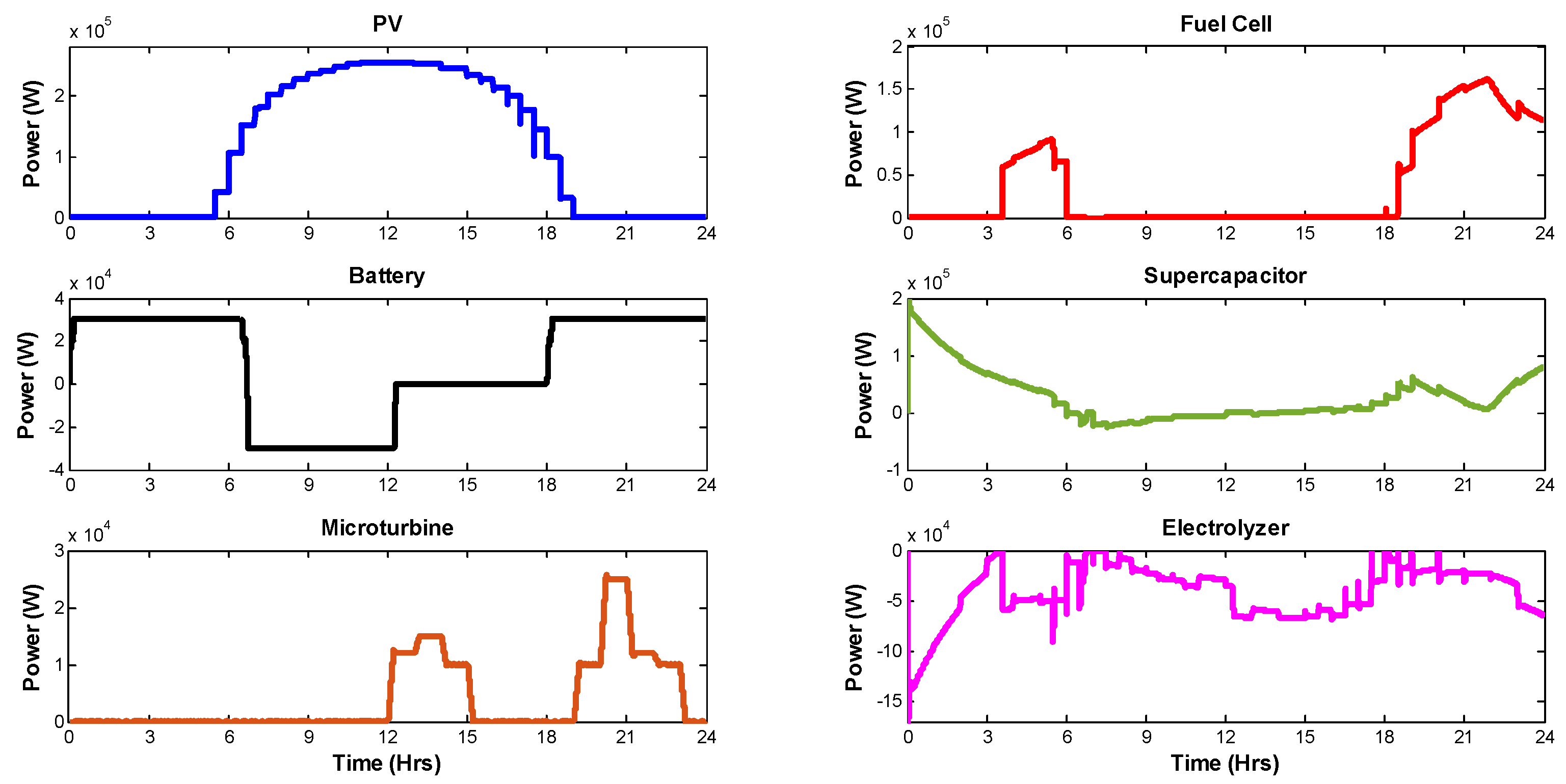
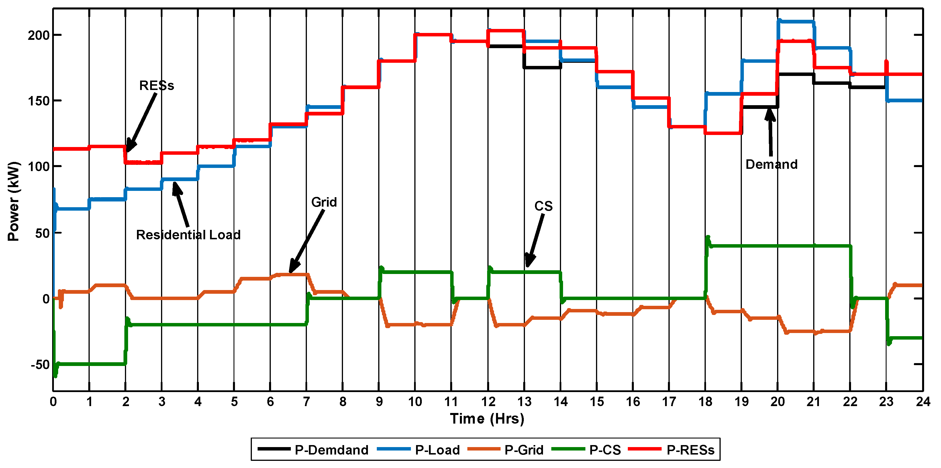
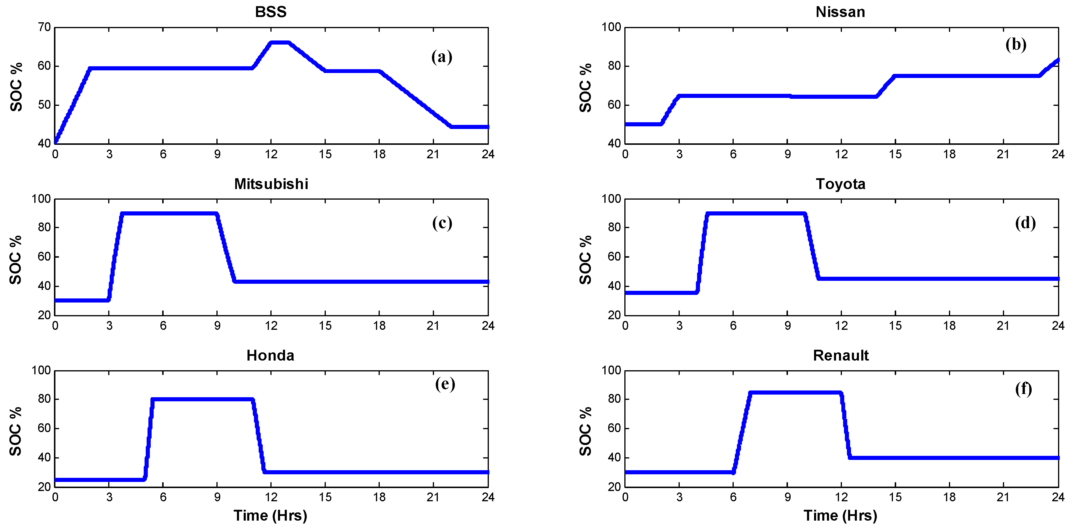
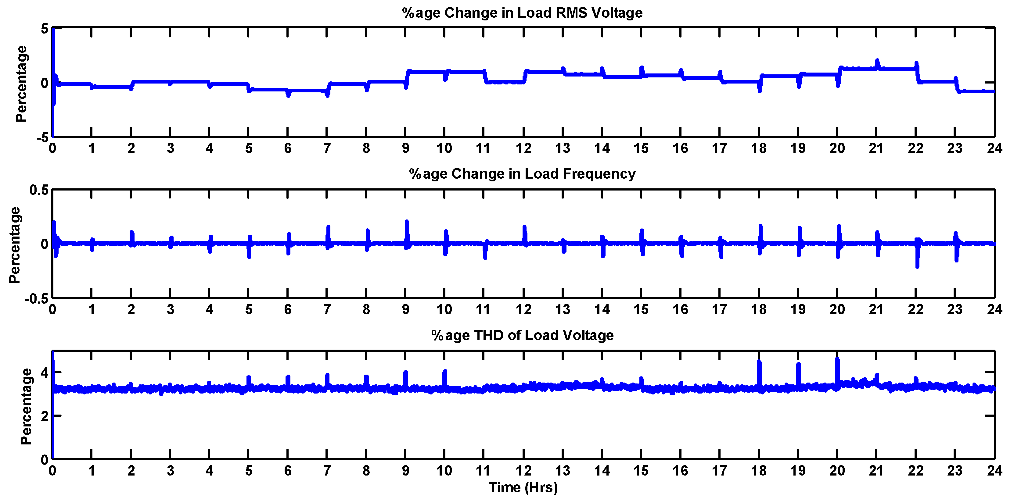
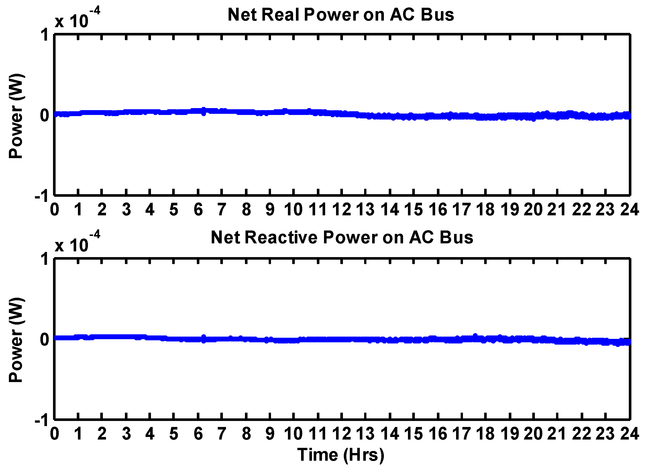
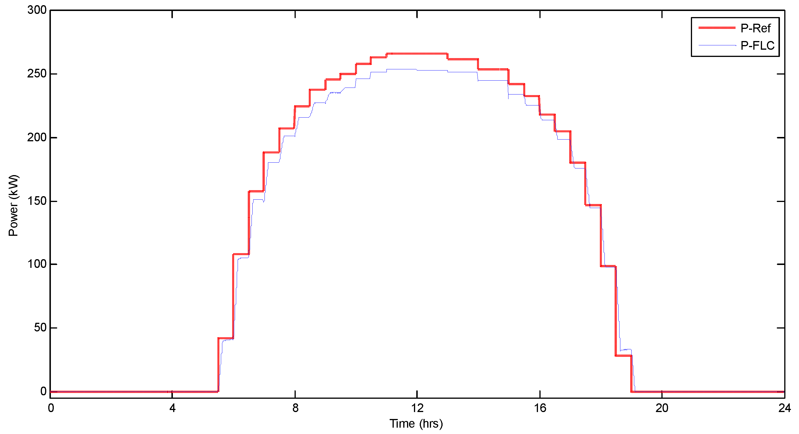
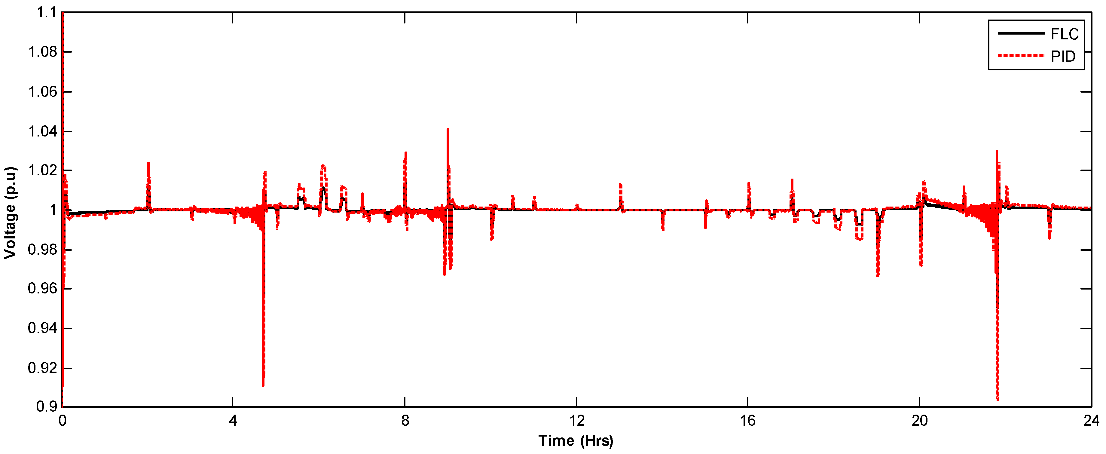
6. Simulation Results

To evaluate the proposed PMS, simulations were performed in MATLAB/Simulink and the modes of operation are verified. The simulation started at midnight and finished at midnight the next day, on 22 July 2017, in Islamabad, Pakistan. The simulation was performed on an hourly basis for the energy available from the RESs, utility grid and accordingly manages the charging demand of PHEVs/EVs and demand of residential load. The goal was to observe the response of the proposed system over a long period of time including day and night cases. The PHEV/EV battery SOC was used to calculate the charging time and charging energy when the vehicles enter the charging station.
It is important to mention that level 3 (DC fast charging) was used to charge the PHEVs/EVs in this simulation. On fast charging, the vehicle battery takes approximately 30 min to fully charge. The data used for simulation are shown in Table 2. The PV output power obtained by the fuzzy controller is shown in Figure 7. The individual powers available from the PV, SOFC, MT, SC module and the battery bank are shown in Figure 8. The total available power from the different energy sources and the total demand including residential load, CS load and utility grid are shown in Figure 9. To make the discussion simple, the net power available from the PV, SOFC, MT, SC module and the battery bank is represented by P-RESs.
During t = 0–2 h, it is obvious that the power delivered by the RESs exactly satisfies the total demand. The CS is receiving power from both the RESs and grid, but a higher share of power comes from the RESs, viz., the total demand of the CS in this interval is 100 kW in which the RESs’ share is 85 kW, while the utility grid provides 15 kW. In addition, it is noticeable that at this interval there is no PHEVs/EVs present for the charging, therefore the total power received from the AC bus is used to charge the BSS through DC-DC converter and its SOC increases from 40% to 60% (Scenario 5) as shown in Figure 10a and Figure 11. The charged BSS could help to reduce the stress on the grid during the peak times. During t = 2–4 h, the CS need 40 kW power which is completely provided by RESs. This power is utilized to charge the Mitsubishi i-MiEV and Nissan leaf vehicles and their batteries’ SoCs go from 50% to 65% and 30% to 90%, respectively (Scenario 3, Figure 10b,c). Most of the vehicles come for charging at night due to the normal or low electricity price which could be used in rush hours under the V2G scheme, e.g., during t = 4–7 h, Toyota Prius plug-in, Honda Accord Hybrid and Renault Kangoo Z.E vehicles are charged from the AC bus. A total of 60 kW power is utilized to charge all these three vehicles. Among 60 kW, the RESs contribute 38 kW, while the grid provides 22 kW.
The charging station demand is zero during t = 7–9 h (Scenario 1), hence, both the RESs and utility grid are used to meet the residential load demand. Some of the discharged PHEVs/EVs wants to discharge under the revenue opportunity scheme during peak times. For example, during t = 9–11 h, Mitsubishi i-MiEV and Toyota Prius plug-in supply 40 kW power combined to the AC bus (Scenario 2), which is then transferred to the grid through the CS inverter, as shown in Figure 10b,c and Figure 11.
Similarly, Renault Kangoo Z.E provides 20 kW to the AC bus during t = 12–13 h, which is completely transferred to the utility grid because the RESs satisfy the residential load, as shown in Figure 9. During t = 13–14 h, the residential demand increases and needs 5 kW. According to the PMS, the required power is provided from the BSS. A total of 20 kW is transferred from the BSS to the AC bus and thus the SoC decreases from 66% to 62% (Scenario 5). Out of 20 kW, the residential load utilizes 5 kW, while the remaining 15 kW is sent to the utility grid via the CS inverter and thus the total demand decreases.
Those PHEVs that want to be charged from the BSS are covered during t = 14–15 h, viz., Nissan leaf has received power from the BSS (Scenario 6) and it increases from 65% to 75%, as shown in Figure 10a,b and Figure 11. In this interval, the RESs first satisfy the residential load demand while the remaining 10 kW power is sent to the utility grid. The demand of the CS is zero during t = 15–18 h, therefore the RESs meet the residential load while the remaining excess power, i.e., 19 kW, is sent to the utility grid. Figure 9 shows that the peak hours occur during t = 18–22 h, viz., the residential load is at peak, the utility grid cannot provide the power due to the rush hours, and the RESs cannot meet the residential load; therefore, the BSS provides 160 kW power to the AC bus. The AC bus then provides 85 kW to the grid while the remaining 75 kW power is utilized to satisfy the residential load demand. Similarly, Scenarios 1 and 3 are repeated during t = 22–23 h and t = 23–24 h, respectively.
The power quality and grid stability parameters such as RMS load voltage, load frequency and net power at AC bus are shown in Figure 12 and Figure 13. The net power on the AC bus is zero, which indicates that the overall system and grid are stable. The RMS load voltage, load frequency deviation and DC bus voltage deviation are in limits according to the IEC61000 and IEEE 519-2014 standards.
The proposed PMS based on FLC is also compared with that based on PID controllers. Figure 14 illustrates the changes in the DC bus voltage obtained by both PMSs. The simulation results show that the proposed FLC (denoted as black) has a faster response, smaller overshoot and maintains better DC bus voltage compared to the standard PID controller (denoted as red).

7. Conclusions

Without proper management, the penetration of PHEVs in the transportation sector can cause a burden on the distribution systems, especially when many PHEVs are connected to the grid at peak-hours. To face this concern, the distribution system requires to be improved to carry new loads. The enhancement of conventional grids to smart grids will create a proper management system to control the PHEVs charging and avoid the distribution transformer from being overloaded. To further increase the benefits of PEHVs, it is essential to take power from the RESs for the PHEVs charging. This paper proposes a PHEVs/EVs CS structure using a high share of power from the RESs and proper power management strategies. The proposed PMS managed the PHEVs charging in such a way that their charging does not become a burden on the utility during peak hours. The paper also provides the integration and coordination of different RESs. This paper shows that the PHEV charging demand does not disturb the grid stability and power quality parameters of the proposed system.

Author Contributions

T.K., and L.K. designed the algorithm in this work. S.Z.H., M.H.R., M.T.R. and M.A.K. were responsible for the preparation of required material. M.K. and L.M.F.-R. analyzed the results. All authors contributed at different stages.

Funding

This work was partially funded by the Turkish government under “Türkiye Bursları 2015–2020”.

Acknowledgments

Thanks to University of Cadiz, Spain for providing technical support under the framework of the Erasmus program of the European Commission.

Conflicts of Interest

The authors declare no conflict of interest.

References

  1. Clarke, A.D.; Makram, E.B. An Innovative Approach in Balancing Real Power Using Plug in Hybrid Electric Vehicles. J. Power Energy Eng. 2014, 2, 1–8. [Google Scholar] [CrossRef]
  2. Anumolu, P.; Banhazl, G.; Hilgeman, T.; Pirich, R. Plug-in hybrid vehicles: An overview and performance analysis. In Proceedings of the 2008 IEEE Long Island Systems, Applications and Technology Conference, Farmingdale, NY, USA, 2 May 2008; pp. 1–4. [Google Scholar]
  3. Tie, S.F.; Tan, C.W. A review of energy sources and energy management system in electric vehicles. Renew. Sustain. Energy Rev. 2013, 20, 82–102. [Google Scholar] [CrossRef]
  4. Cowell, R. Global Energy Justice: Problems, Principles, and Practices. J. Environ. Plan. Ploicy Manag. 2016, 18, 253–255. [Google Scholar] [CrossRef]
  5. Nurre, S.G.; Bent, R.; Pan, F.; Sharkey, T.C. Managing operations of plug-in hybrid electric vehicle (PHEV) exchange stations for use with a smart grid. Energy Policy 2014, 67, 364–377. [Google Scholar] [CrossRef]
  6. Su, W.; Chow, M.-Y. An intelligent energy management system for PHEVs considering demand response. In Proceedings of the 2010 FREEDM Annual Conference; 2010. Available online: http://citeseerx.ist.psu.edu/viewdoc/download?doi=10.1.1.455.8086&rep=rep1&type=pdf (accessed on 15 May 2018).
  7. Su, W.; Zeng, W.; Chow, M.-Y. A digital testbed for a PHEV/PEV enabled parking lot in a smart grid environment. In Proceedings of the 2012 IEEE PES Innovative Smart Grid Technologies (ISGT), Washington, DC, USA, 16–20 January 2012; pp. 1–7. [Google Scholar]
  8. Yılmaz, S.; Ustaoğlu, M. Electric Vehicles Production in Turkish Automotive Industry and Sectoral PEST Analisys. Proced. Soc. Behav. Sci. 2013, 75, 10–17. [Google Scholar] [CrossRef]
  9. Khan, A.S. Big Bets Coming on Local Assembly of Electric Cars. Available online: https://www.dawn.com/news/1413157 (accessed on 18 May 2018).
  10. Kamran, M. Current status and future success of renewable energy in Pakistan. Renew. Sustain. Energy Rev. 2018, 82, 609–617. [Google Scholar] [CrossRef]
  11. National Houshold Travel Survey (NHTS). Summary of Travel Trends-2009. Available online: https://nhts.ornl.gov/2009/pub/stt.pdf (accessed on 12 May 2018).
  12. Green, R.C.; Wang, L.; Alam, M. The impact of plug-in hybrid electric vehicles on distribution networks: A review and outlook. Renew. Sustain. Energy Rev. 2011, 15, 544–553. [Google Scholar] [CrossRef]
  13. Shao, S.; Pipattanasomporn, M.; Rahman, S. Challenges of PHEV penetration to the residential distribution network. In Proceedings of the 2009 IEEE Power & Energy Society General Meeting, Calgary, AB, Canada, 26–30 July 2009; pp. 1–8. [Google Scholar]
  14. Rutherford, M.J.; Yousefzadeh, V. The impact of electric vehicle battery charging on distribution transformers. In Proceedings of the 2011 Twenty-Sixth Annual IEEE Applied Power Electronics Conference and Exposition (APEC), Fort Worth, TX, USA, 6–11 March 2011; pp. 396–400. [Google Scholar]
  15. Nagarajan, A.; Shireen, W. Grid connected residential photovoltaic energy systems with Plug-In Hybrid electric Vehicles (PHEV) as energy storage. In Proceedings of the IEEE PES General Meeting, Providence, RI, USA, 25–29 July 2010; pp. 1–5. [Google Scholar]
  16. Preetham, G.; Shireen, W. Photovoltaic charging station for plug-in hybrid electric vehicles in a smart grid environment. In Proceedings of the 2012 IEEE PES Innovative Smart Grid Technologies (ISGT), Washington, DC, USA, 16–20 January 2012; pp. 1–8. [Google Scholar]
  17. Goli, P.; Shireen, W. PV Integrated Smart Charging of PHEVs Based on DC Link Voltage Sensing. IEEE Trans. Smart Grid 2014, 5, 1421–1428. [Google Scholar] [CrossRef]
  18. Goli, P.; Shireen, W. PV powered smart charging station for PHEVs. Renew. Energy 2014, 66, 280–287. [Google Scholar] [CrossRef]
  19. Zhao, J.; Kucuksari, S.; Mazhari, E.; Son, Y.-J. Integrated analysis of high-penetration PV and PHEV with energy storage and demand response. Appl. Energy 2013, 112, 35–51. [Google Scholar] [CrossRef]
  20. Oviedo, R.J.M.; Fan, Z.; Gormus, S.; Kulkarni, P.; Kaleshi, D. Residential energy demand management in smart grids. In Proceedings of the PES T&D 2012, Orlando, FL, USA, 7–10 May 2012; pp. 1–8. [Google Scholar]
  21. Erol-Kantarci, M.; Mouftah, H.T. Management of PHEV batteries in the smart grid: Towards a cyber-physical power infrastructure. In Proceedings of the 2011 7th International Wireless Communications and Mobile Computing Conference, Istanbul, Turkey, 4–8 July 2011; pp. 795–800. [Google Scholar]
  22. Heydt, G.T. The Impact of Electric Vehicle Deployment on Load Management Strategies. IEEE Trans. Power Appar. Syst. 1983, 1253–1259. [Google Scholar] [CrossRef]
  23. Heider, A.; Haubrich, H.-J. Impact of wide-scale EV charging on the power supply network. In Proceedings of the IEE Colloquium on Electric Vehicles—A Technology Roadmap for the Future, London, UK, 5 May 1998. [Google Scholar]
  24. Zhang, Q.; Tezuka, T.; Ishihara, K.N.; Mclellan, B.C. Integration of PV power into future low-carbon smart electricity systems with EV and HP in Kansai Area, Japan. Renew. Energy 2012, 44, 99–108. [Google Scholar] [CrossRef]
  25. Denholm, P.; Kuss, M.; Margolis, R.M. Co-benefits of large scale plug-in hybrid electric vehicle and solar PV deployment. J. Power Sources 2013, 236, 350–356. [Google Scholar] [CrossRef]
  26. Ma, Z.; Callaway, D.; Hiskens, I. Decentralized charging control for large populations of plug-in electric vehicles: Application of the Nash certainty equivalence principle. In Proceedings of the 2010 IEEE International Conference on Control Applications, Yokohama, Japan, 8–10 September 2010; pp. 191–195. [Google Scholar]
  27. Hota, A.R.; Juvvanapudi, M.; Bajpai, P. Issues and solution approaches in PHEV integration to smart grid. Renew. Sustain. Energy Rev. 2014, 30, 217–229. [Google Scholar] [CrossRef]
  28. Hamilton, C.; Gamboa, G.; Elmes, J.; Kerley, R.; Arias, A.; Pepper, M.; Shen, J.; Batarseh, I. System architecture of a modular direct-DC PV charging station for plug-in electric vehicles. In Proceedings of the IECON 2010—36th Annual Conference on IEEE Industrial Electronics Society, Glendale, AZ, USA, 7–10 November 2010; pp. 2516–2520. [Google Scholar]
  29. Bauer, P.; Zhou, Y.; Doppler, J.; Stembridge, N. Charging of electric vehicles and impact on the grid. In Proceedings of the 13th Mechatronika 2010, Trencianske Teplice, Slovakia, 2–4 June 2010; pp. 121–127. [Google Scholar]
  30. Arancibia, A.; Strunz, K. Modeling of an electric vehicle charging station for fast DC charging. In Proceedings of the 2012 IEEE International Electric Vehicle Conference, Greenville, SC, USA, 4–8 March 2012; pp. 1–6. [Google Scholar]
  31. Kelly, N.A.; Gibson, T.L. Solar photovoltaic charging of high voltage nickel metal hydride batteries using DC power conversion. J. Power Sources 2011, 196, 10430–10441. [Google Scholar] [CrossRef]
  32. Gibson, T.L.; Kelly, N.A. Solar photovoltaic charging of lithium-ion batteries. In Proceedings of the 2009 IEEE Vehicle Power and Propulsion Conference, Dearborn, MI, USA, 7–10 September 2009; Volume 195, pp. 3928–3932. [Google Scholar] [CrossRef]
  33. Gamboa, G.; Hamilton, C.; Kerley, R.; Elmes, S.; Arias, A.; Shen, J.; Batarseh, I. Control strategy of a multi-port, grid connected, direct-DC PV charging station for plug-in electric vehicles. In Proceedings of the 2010 IEEE Energy Conversion Congress and Exposition, Atlanta, GA, USA, 12–16 September 2010; pp. 1173–1177. [Google Scholar]
  34. Aggeler, D.; Canales, F.; Zelaya, H.; La Parra, D.; Coccia, A.; Butcher, N.; Apeldoorn, O. Ultra-fast DC-charge infrastructures for EV-mobility and future smart grids. In Proceedings of the 2010 IEEE PES Innovative Smart Grid Technologies Conference Europe (ISGT Europe), Gothenberg, Sweden, 11–13 October 2010; pp. 1–8. [Google Scholar]
  35. Kulshrestha, P.; Wang, L.; Chow, M.-Y.; Lukic, S. Intelligent energy management system simulator for PHEVs at municipal parking deck in a smart grid environment. In Proceedings of the 2009 IEEE Power & Energy Society General Meeting, Calgary, AB, Canada, 26–30 July 2009; pp. 1–6. [Google Scholar]
  36. Nehrir, M.H. Power Management of a Stand-Alone Wind/Photovoltaic/Fuel Cell Energy System. IEEE Trans. Energy Convers. 2008, 23, 957–967. [Google Scholar] [CrossRef]
  37. Drude, L.; Pereira Junior, L.C.; Rüther, R. Photovoltaics (PV) and electric vehicle-to-grid (V2G) strategies for peak demand reduction in urban regions in Brazil in a smart grid environment. Renew. Energy 2014, 68, 443–451. [Google Scholar] [CrossRef]
  38. Onar, O.C.; Uzunoglu, M.; Alam, M.S. Modeling, control and simulation of an autonomous wind turbine/photovoltaic/fuel cell/ultra-capacitor hybrid power system. J. Power Sources 2008, 185, 1273–1283. [Google Scholar] [CrossRef]
  39. Li, C.-H.; Zhu, X.-J.; Cao, G.-Y.; Sui, S.; Hu, M.-R. Dynamic modeling and sizing optimization of stand-alone photovoltaic power systems using hybrid energy storage technology. Renew. Energy 2009, 34, 815–826. [Google Scholar] [CrossRef]
  40. Uzunoglu, M.; Alam, M.S. Dynamic Modeling, Design, and Simulation of a Combined PEM Fuel Cell and Ultracapacitor System for Stand-Alone Residential Applications. IEEE Trans. Energy Convers. 2006, 21, 767–775. [Google Scholar] [CrossRef]
  41. El-Shatter, T.F.; Eskandar, M.N.; El-Hagry, M.T. Hybrid PV/fuel cell system design and simulation. Renew. Energy 2002, 27, 479–485. [Google Scholar] [CrossRef]
  42. Zhu, Y.; Tomsovic, K. Development of models for analyzing the load-following performance of microturbines and fuel cells. Electr. Power Syst. Res. 2002, 62, 1–11. [Google Scholar] [CrossRef] [Green Version]
  43. Hajizadeh, A.; Golkar, M.A. Intelligent Control of Fuel Cell Distributed Generation Systems. In Proceedings of the 2007 International Conference on Intelligent Systems Applications to Power Systems, Niigata, Japan, 5–8 November 2007; pp. 1–7. [Google Scholar]
  44. Khan, M.J.; Iqbal, M.T. Analysis of a small wind-hydrogen stand-alone hybrid energy system. Appl. Energy 2009, 86, 2429–2442. [Google Scholar] [CrossRef]
  45. Prius Plug-in Hybrid. 2014. Available online: http://www.toyota.com/prius-plug-in/features.html#!/mechanical/1235/1237 (accessed on 25 March 2017).
  46. Mitsubishi. Mitsubishi i-MiEV Technical Specifications Consulted. 2011. Available online: http://www.mitsubishi-motors.com/special/ev/whatis/index.html (accessed on 20 March 2017).
  47. Nissan. Nissan Leaf Technical Specifications. Consulted. 2011. Available online: http://www.nissan.co.uk/vehicles/electricvehicles/leaf.htm#vehicles/electricvehicles/leaf/leaf-engine/specifications (accessed on 30 March 2018).
  48. Renault. Renault Kangoo Z.E. Technical Specification. Consulted. 2011. Available online: http://www.renault.com/en/vehicules/renault/pages/kangoo-express-ze.aspx (accessed on 22 March 2018).
  49. Accord Plug-in. 2014. Available online: http://automobiles.honda.com/accord-plug-in/ (accessed on 15 March 2018).
Figure 1. Proposed hybrid smart micro-grid system.
Electronics 07 00156 g001
Figure 2. Structure of electric charging station.
Electronics 07 00156 g002
Figure 3. Schematic diagram of a buck boost converter/voltage regulator.
Electronics 07 00156 g003
Figure 4. Schematic diagram of charging station converter control.
Electronics 07 00156 g004
Figure 5. Fuzzy logic controller model.
Electronics 07 00156 g005
Figure 6. Flow chart of the proposed PMS: (a) initial decision stage of the PMS; (b) PMS working at off peak hours; and (c) PMS working at peak hours.
Electronics 07 00156 g006
Figure 7. PV output power.
Electronics 07 00156 g007
Figure 8. Individual powers of RESs.
Electronics 07 00156 g008
Figure 9. Power of all the energy sources and total demand in the proposed micro-grid.
Electronics 07 00156 g009
Figure 10. State of charge of the BSS and PHEVs.
Electronics 07 00156 g010
Figure 11. SOC of the BSS/PHEVs and CS power using the proposed PMS.
Electronics 07 00156 g011
Figure 12. Power quality parameters.
Electronics 07 00156 g012
Figure 13. Grid stability parameters.
Electronics 07 00156 g013
Figure 14. DC bus voltage deviation: PMS based on FLC versus PMS based on PID controllers.
Electronics 07 00156 g014
Table 1. RESs and their power converter parameters [36,38,42,43,44].
PV ArrayBattery
TypeSunPower SPR-305-WHTTypeCINCO FM/BB12100T
Module 305 W @ 1 kW/m2, 25 °CCapacity50 Ah
Number of series/string13Single module voltage12 V
Number of parallel strings66No of series connected modules34
Power Rating305 × 13 × 66 ≈ 262 kWRated Voltage12 × 34 ≈ 400 V
SupercapacitorFuel Cell Array
TypeMaxwell Boost Cap BMOD0165-48.6VUCTypeBloom Energy USA ES-5700
Capacitance165 FNumber of cells in series in the stack768
Number of series capacitors50SOFC Stack4 kW
Number of parallel capacitors20SOFC Array5 × 10 = 50
No of modules12SOFC Array Power Rating50 × 4 kW = 200 kW
Rated Voltage12 × 48.6 ≈ 584 V
ElectrolyzerMicroturbine
TypeQualeanQL-85000TypeIngersoll Rand MT250
Rated Power30 kWRated Power200 kVA, 160 kW
Rated Voltage380 VRated Voltage440 V
Number of Cells in Stack30Rated Frequency50 Hz
Utility GridMain Inverter
Phase Voltage11 kVTypeZhejiang, China CHZIRI-2VF
Rated Power10 MVARated Power400 kW
Phase Frequency50 HzRated Voltage200/540 V
Table 2. PHEVs technical details [45,46,47,48,49].
Company NameVehicle NameBattery TypeBattery Capacity (kWh)Range (km)Charging Rate (kW)Rated Voltage (V)Charging Time
SlowFastSlowFast
MitsubishiMiEV Li-ion16.0160350207 h30 min
NissanLeafLi-ion24.01606.6503604 h30 min
RenaultKangoo Z.E.Li-ion22.01703433006 h30 min
HondaCivic hybridLi-ion6.71502.213.43003 h30 min
ToyotaPriusLi-ion4.416182015 h30 min
Table 3. Buck boost/voltage regulator parameters of the charging station.
ParameterRepresentationValues
CS DC Buck Boost Converter
Model TypeNCP1136
VratedRated Voltage10/700 V
C1Converter Capacitance2200 μF
L1Converter Inductance1 mH
Kp, Ki, KdPID Gains (T1)1.5, 1, 1
Kp, Ki, KdProportional Gain (T2)1.5, 1, 1
fRated Switching Frequency10 kHz
CS DC Voltage Regulator
Model TypeMC33363ADWG
VratedRated Voltage10/700 V
C2Converter Capacitance4700 μF
KpProportional Gain0.0005
KiIntegral Gain0.15
fRated Switching Frequency10 kHz
CS Converter
Model TypeZhejiang, China CHZIRI-2VF
PratedRated Power220 kW
VratedRated Voltage220/1140 V
fCCarrier Frequency10 kΩ
foutFrequency of Output Voltage50 Hz
CsSnubber Capacitance100 kΩ
RsSnubber Resistance10 kΩ
LInductance L-Filter2.6 μH
Table 4. Possible scenarios.
ScenarioDescription
1No Cars in the CS (Empty CS)
2Vehicles to AC bus
3AC bus to Vehicles
4BSS to AC bus
5AC bus to BSS
6BSS to Vehicles
7Vehicles to BSS

