Article

Improving Performance of Three-Phase Slim DC-Link Drives Utilizing Virtual Positive Impedance-Based Active Damping Control

1
Department of Electrical and Electronics Engineering, Faculty of Technology, Gazi University, 06500 Ankara, Turkey
2
Department of Energy Technology, Aalborg University, AAU 9220 Aalborg East, Denmark
*
Authors to whom correspondence should be addressed.
Electronics 2018, 7(10), 234; https://doi.org/10.3390/electronics7100234
Submission received: 3 September 2018 / Revised: 29 September 2018 / Accepted: 1 October 2018 / Published: 4 October 2018
(This article belongs to the Special Issue Applications of Power Electronics)

Abstract

:
In this paper, a virtual positive impedance (VPI) based active damping control for a slim DC-link motor drive with 24 section space vector pulse width modulation (SVPWM) is proposed. Utilizing the proposed control and modulation strategy can improve the input of current total harmonic distortion (THD) while maintaining the cogging torque of the motor. The proposed system is expected to reduce the front-end current THD according to international standards, as per IEC 61000 and IEEE-519. It is also expected to achieve lower cost, longer lifetime, and fewer losses. A permanent magnet synchronous motor (PMSM) is fed by the inverter, which adopts the 24 section SVPWM technique. The VPI based active damping control for the slim DC-link drive with/without the 24 section SVPWM are compared to confirm the performance of the proposed method. The simulation results based on MATLAB are provided to validate the proposed control strategy.

1. Introduction

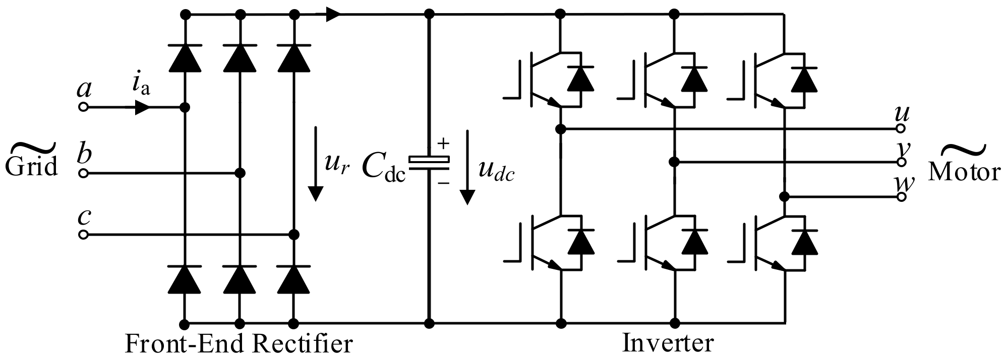
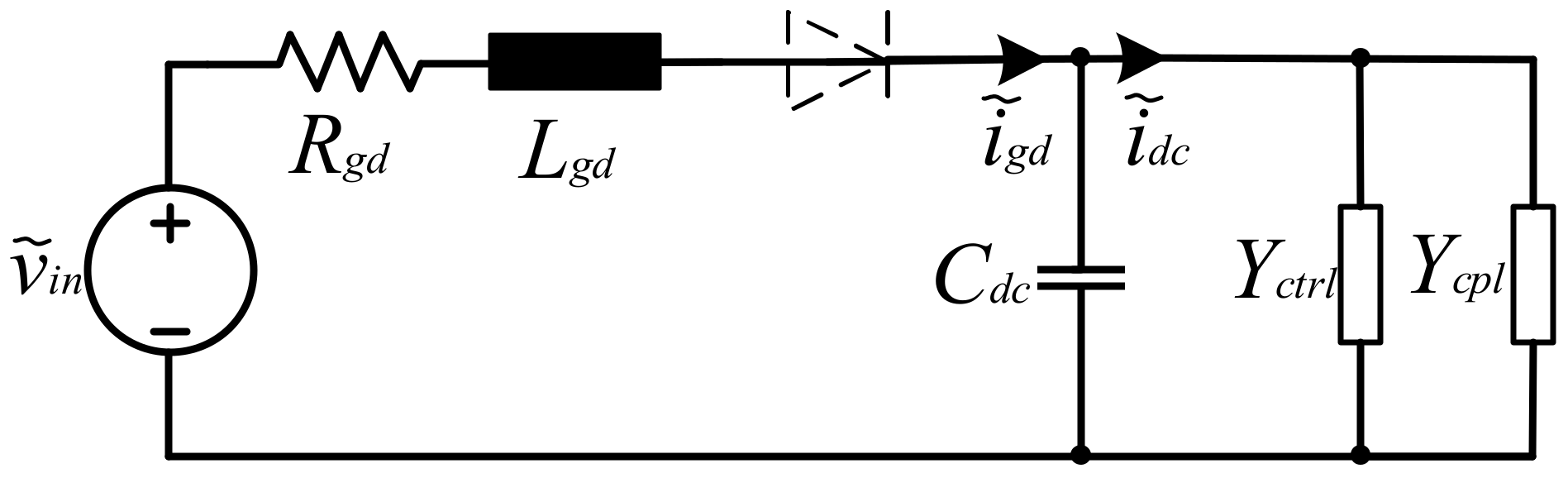
In many industrial applications, slim DC-link drives have become increasingly favored day by day. A classical driver consists of a 6-pulse diode bridge rectifier, an intermediate circuit with a big capacitor, an inductor, and an inverter. To maintain stable DC-link voltage, the DC-link capacitor needs to be carefully selected. Although the big size capacitor with large capacitance is at a higher cost and shorter lifetime, it has strong robustness against the stability problem. However, cost, lifetime, and loss must be taken into consideration for industrial applications. Thus, using a film capacitor as the slim DC-link capacitor in drivers is preferred, in spite of the stability problem. A diode rectifier based slim DC-link drive is shown in 
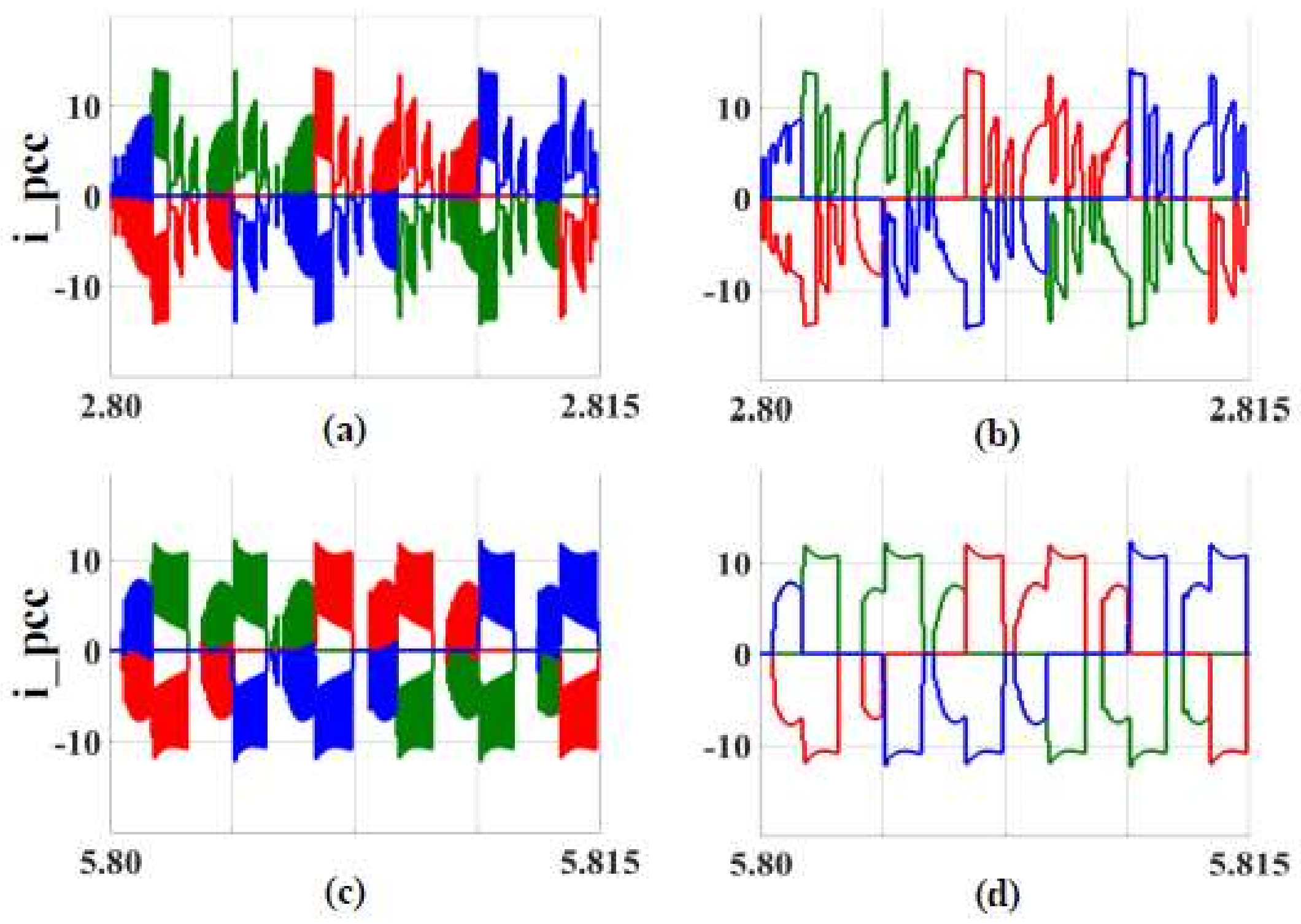
Figure 1. This grid-connected driver has a diode rectifier, a slim DC capacitor, and a 6-switches three-phase inverter. Additionally, point of common coupling (PCC) phase currents for stiff grid and weak grid are given in Figure 2 at different operation speeds. The i_pcc simulated waveforms show that stiff grid and high operation speed (c) is the best current waveform. However, it can be improved with control methods, especially for weak grid conditions.
To solve the stability problem, Virtual Positive Impedance (VPI) based active damping control has been effectively implemented [1,2]. Active damping control for slim DC-link drive ensures that no extra passive damping component is needed. The negative impedance instability is described as:
P L v d c 2 = i d c v d c 0 v d c ( v d c 0 v ˜ ) = ( i d c 0 + i d c ˜ ) v d c 0 v d c ( v d c 0 v ˜ )  
where PL is the load power, vdc0 is the DC component of the DC-link voltage, v ˜ is the AC part of the DC-link voltage, and vdc is the DC-link voltage [1]. idc is the DC-link current, i d c ˜ is the AC part of the DC-link current, and idc0 is the DC component of the DC-link current. In contrast to the case using the big capacitor [3], the constant power load behavior of the motor with a slim-DC-link capacitor causes the larger ripple on the DC voltage. Both ripples on the DC-link voltage and the front-end current harmonics are higher when using a small capacitor [4,5]. In order to reduce the input current harmonics, VPI based active damping control decreases the ripple on the DC-link voltage [1,2,3,
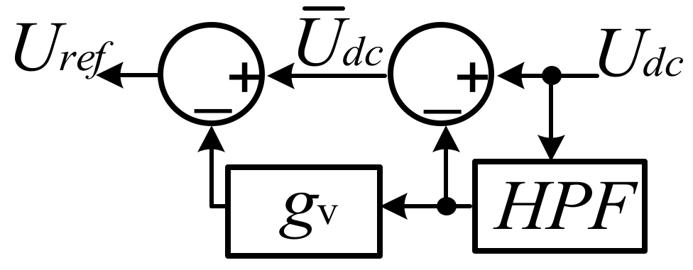
4]. A virtual positive impedance block diagram is illustrated in Figure 3 [1]. This model can be used for the generation of the DC-link voltage reference. In order to control the AC component of the DC-link voltage, the 1st-order High Pass Filter is represented by a high pass filter (HPF) block. gv is the gain on the accompaniment of the DC-link voltage. In spite of the fact that VPI contains an HPF block, it resembles the 1st-order Low Pass Filter and harmonic detection block. Additionally, this block diagram can be used for detecting the harmonic [5]. The harmonic detection is also ensured by the VPI method, providing the lower ripples on the DC-link voltage. Harmonic mitigation, harmonic cancellation, or generally a harmonic problem is an important issue for motor drivers [6,7]. This problem can deteriorate grid voltage quality, as well as the performance of both the driver and the load. Although it cannot be completely removed, it needs to be mitigated as much as possible. For this purpose, several control techniques and PWM techniques have been studied [8,9,10].
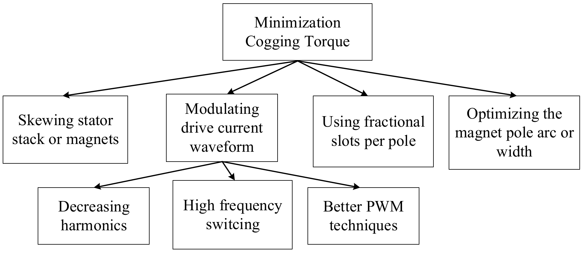
At the same time, not only ripple on the DC-link voltage on a small capacitor, but also a motor cogging torque due to interactions between core and magnet result in both grid input current harmonics and motor current harmonics. Owing to the harmonic problem, active damping control (ADC) and VPI can be used to decrease THD. Even through these methods achieve harmonics suppression, the cogging torque also needs to be solved by harmonic effect, because motor current harmonics cause the higher cogging torque [11,12,13,14,15,
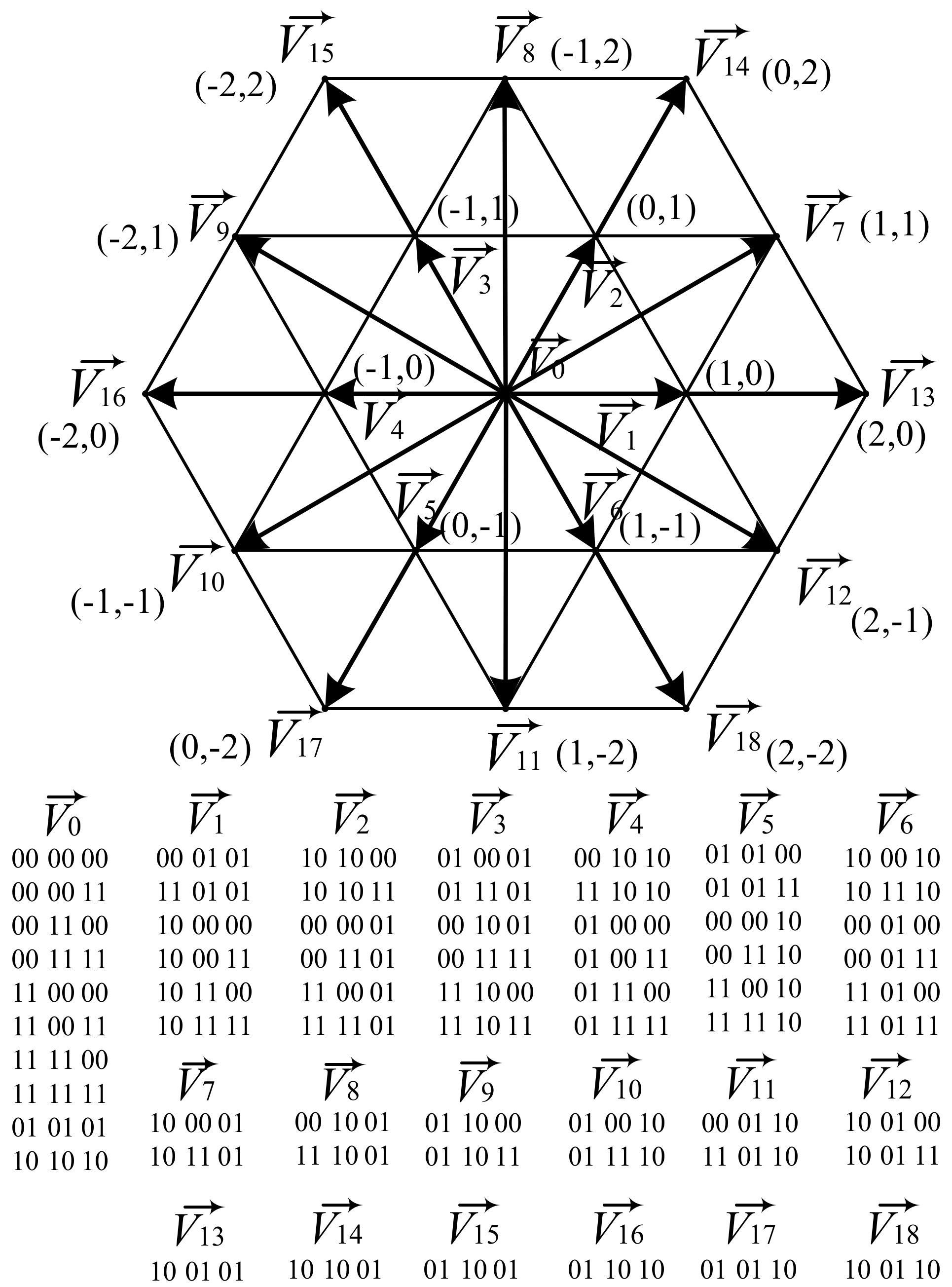
16]. When the 3DSVPWM aims to optimize switching waveforms, it can achieve a lower cogging torque. The algorithm of the 3DSVPWM was based on four steps. Firstly, the reference vector was transformed into 2D. In addition, the length of the reference vector was described according to the length of the basis vectors. Secondly, the closest three vectors were found. When they were detected, finding high–low values of the reference vector coordinates could be facilitated. Duty cycles were calculated in the third step. Lastly, the best switching states were selected when 2D coordinates are transformed to 3D coordinates [9,12].
In this study, the DC-link voltage, the grid input current THD, the VPI bode results, the cogging torque, and the THD of motor currents were simulated in MATLAB (R2016b, MathWorks, Natick, MA, USA), where four simulation models were developed: (1) Weak grid without VPI without 3DSVPWM (wOVPIwO3D), (2) weak grid with VPI without 3DSVPWM (wVPIwO3D), (3) weak grid with VPI with 3DSVPWM (wVPIw3D), and (4) stiff grid with VPI with 3DSVPWM (stiffwVPIw3D).
Simulation results of these models are compared and discussed. Section 2 analyzes the interaction between the cogging torque and the current harmonic. The 3DSVPWM, the PMSM model, and the input admittance are described. Then, virtual positive impedance based active damping control is given in Section 3. In Section 4, the performance analysis of the DC-link current THD and the motor current THD of the slim DC-link capacitor is shown. In addition, the stability analysis, the control structure, and the control impedance Yctrl are explained in the same section. Additionally, the simulation validation of the grid input current THDi and the cogging torque are obtained. Lastly, the study is summarized in Section 5.

2. Interaction between Cogging Torque and Harmonic

2.1. The Cogging Torque Reduction Methods

In order to decrease the cogging torque, some methods are used. These are mainly:
  • Skewing stator stack or magnets;
  • Modulation drive current waveform;
  • Using fractional slots per pole;
  • Optimizing the magnet pole arc or width [9,17].
The schema of the cogging torque reduction is illustrated in Figure 4. In order to obtain a better modulation drive current waveform, there are three main methods. They are decreasing harmonics, switching at high frequency, and using advanced PWM techniques [9,17].
On the other hand, the kth harmonic is related to the cogging torque, as expressed in (2). Tck is the amplitude of the kth harmonic component of the cogging torque, θ is the angle of rotation, and k is the order of cogging harmonics.
T c k ( θ ) = n = T n e 2 n i ( θ k θ s )  
where Tn is the Fourier series coefficient and θs is the electrical angle slot pitch. It is expressed as:
θ s = π N m / N s  
where Nm is the number of the magnet pole and Ns is the number of the slot. Accordingly, the cogging torque Tcog can be written as the Fourier series as:
T c o g ( θ ) = k = 0 N s 1 T c k ( θ )  
The proposed models are applied not only for achieving a reduced cogging torque, but also improving system stability thanks to decreased harmonics. Given the fact that the Tck is decreased, the cogging torque can be reduced.

2.2. 3DSVPWM Technique

In the proposed modulation technique, there are 24 sectors, including zero voltage vectors [9]. The modulation space is divided into 6 sections (S1–S6), each section consisting of 4 delta sectors (Δ1, Δ2, Δ3, Δ4).
This proposed modulation technique is adopted in the 3-phase 3-level or multilevel inverter. However, it is used in this study in the 3-phase 2-level inverter. Thus, modulation angles are made smaller and the number of the sector is increased in sections. Here, using the definition of the vector norm, the vectors of the inverter are defined in a plane as given in (5):
v a b + v b c + v c a = 0  
where vab, vbc, and vca are the vectors of the inverter in the 3D coordinate system. The switching state vectors are shown in Figure 5 [18,19]. Additionally, the numbers of 0, 1, and 2 in Figure 5 represent Vab, Vbc, or Vca/Vdc.
According to (5) and Figure 5, the delta vectors can be expressed in the 2D coordinate system as:
V 1 ( v a b , v b c , v c a ) , V 2 ( v a b , v b c , v c a ) = [ V d c 0 V d c ] , [ 0 V d c V d c ]  
where, V 1(vab, vbc, vbc) and V 2(vab, vbc, vbc) are the delta vectors. They are the transformed vectors from 3D to 2D. The reference vector can be placed in a sector and the switching-state vector is shown at the corner of each sector. It is able to produce switching-state vectors in 2D, which are then transformed into 3D switching-state vectors.
This 24 sectors SVPWM technique can eliminate the need for dead-time protection and allow the upper and lower switches to switch at the same time. In this case, the dead-time effect is removed, an additional midpoint voltage is generated, and the effective output switching frequency is doubled. Thus, the current harmonics in the output current waveform are significantly suppressed by applying the three-level voltage output and doubling the effective switching frequency. In order to reduce the current harmonics, the adjacent three vectors and the reference vector must be defined in the best way. Vx, Vy, and Vz are the adjacent three vectors as follow:
T s = d x + d y + d z  
V r e f = d x V x + d y V y + d z V y  
where the dwell time of vectors are dx, dy, and dz, respectively. The reference vector is determined in the hexagon to state which triangle will be used. The biggest difference between 3DSVPWM and classical SVPWM is dwell times: The 3DSVPWM provides better dwell times for switching angles.

2.3. PMSM Model

The PMSM motor is modeled in the dq reference frame, which relies on the field oriented control (FOC), and the mathematical equations are given below:
[ v s d v s q ] = [ R + s L s d ω r L s q ω r L s d R + s L s q ] [ i s d i s q ] + [ 0 ω r λ ]  
T e = 3 2 P ( λ i s q + ( L s d L s q ) i s d i s q )  
where the R, λ, P, Lsd, Lsq, Te, and ωr represent the stator resistor, the flux produced by the permanent magnets, the number of pole pairs, the stator inductances in the dq-frame, the electrical torque, and the rotor speed individually. In addition, vsd, vsq, isd, and isq represent the stator voltages and the stator currents in the dq-frame, respectively. Due to the fact that the speed and current loops force the stator current isd to be 0, (9) can be rewritten as:
V s d = ω r L s q i s q  
V s q = R i s q + s L s q i s q + ω r λ  

2.4. Input Admittance

Using the above equations, the input admittance of the control block and the constant power load are specified as follow:
G i q = 1 Z q + F i q V q V d c ( 1 + g v D A )  
G i d = 1 Z d + F i d V q V d c ( 1 + g v D A )  
G v d = 3 2 ( Z d I d + V d + ω r L d I q + 3 2 ( L d L q ) 2 I d I q 2 N p p 2 J s )
G v q = 3 2 ( Z q I q + V q ω r L q I d + 3 2 ( L d L q ) 2 I q I d 2 N p p 2 J s )
Y i n = 1 Z i n = G v d G i d + G v q G i q V d c + P L V d c 2  
1 Y c t r l = V d c G v d G i d + G v q G i q  
Yctrl is the admittance of the control part with VPI based active damping control and Y c p l (−PL/Vdc2) is the admittance of the constant power load behavior. D, A, Npp, J, Zdq, Fid, and Fiq relate the PWM delay, the 1st-order HPF, the pole-pairs, the inertia, the dq-axis impedance of the PMSM, and the current controller of the dq-axis separately. Two input admittances in (17) are illustrated with an equivalent DC-link circuit in Figure 6, which is on simplified equivalent circuit model of the diode rectified based slim DC-link drive.

3. Virtual Positive Impedance Based Active Damping Control

The parameters of the drive and the PMSM are given in Table 1. Moreover, the sample period is Ts, the reference torque of 3 ph trapezoidal motor is Tm, Cdc is the slim DC-link capacitor value, SCR is the short circuit ratio, and the stator resistive and inductive values are R and Ld
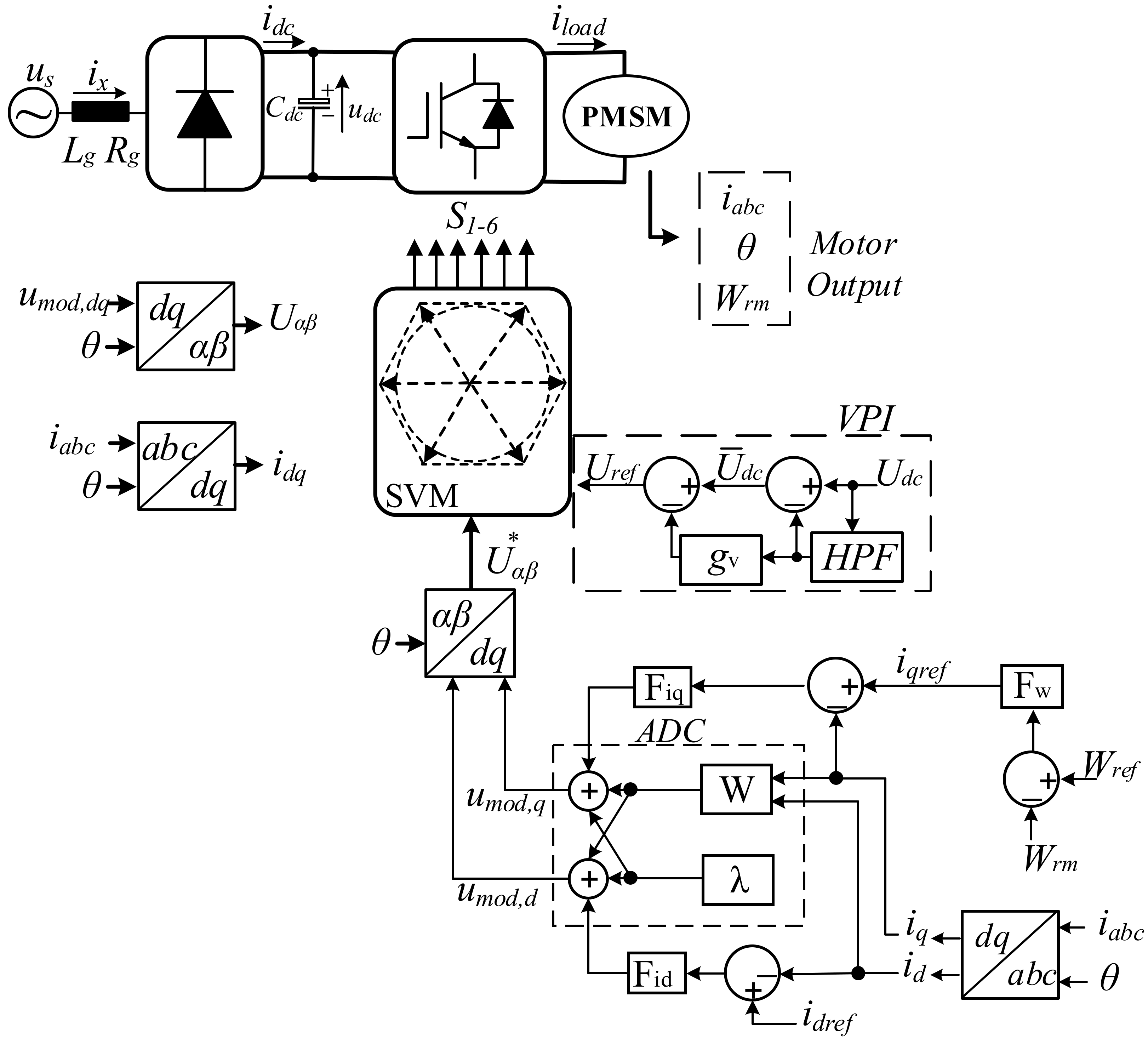
Lq. In addition, the current loop, the speed loop, and PWM block are shown in Figure 7.
The control diagram includes the Space Vector Modulation (SVM) block, together with a VPI and an ADC block, the Park and the inverse Park transformation, the speed controller Fω, the current controller Fiq and Fid together with the decoupling block W. All the components are assumed as ideal. The power loss and the saturation effects in the drive system are neglected. The VPI is illustrated in Figure 3; Udc is the voltage feedback from the slim DC-link capacitor, which is used for voltage ripple elimination. Then, Uref is the control reference of the Vdc, which is calculated based on the reference voltages is 400 V, and the sum of the reversed voltage is −Udc.
Furthermore, the speed closed-loop control and the current closed-loop control are shown in Figure 7 in the dq-frame. W is the decoupling function block presented in Equation (19) and ωr is the rotor speed. The current control equation is shown in Equation (20) and the speed control equation is shown in Equation (21) as follows:
W = [ 0 ω r L q ω r L d 0 ]  
u mod , d q ( t ) = K p [ i d q , r e f ( t ) i d q ( t ) ] + K i [ i d q , r e f ( t ) i d q ( t ) ] + 2 λ + i d q ( t ) W
i q ( t ) = K p [ ( ω r e f ( t ) ω r ( t ) ) ] + K i T s ( ω r e f ( t ) ω r ( t ) )  

4. Performance Analysis of The DC-Lınk Voltage THD and the Motor Current THD

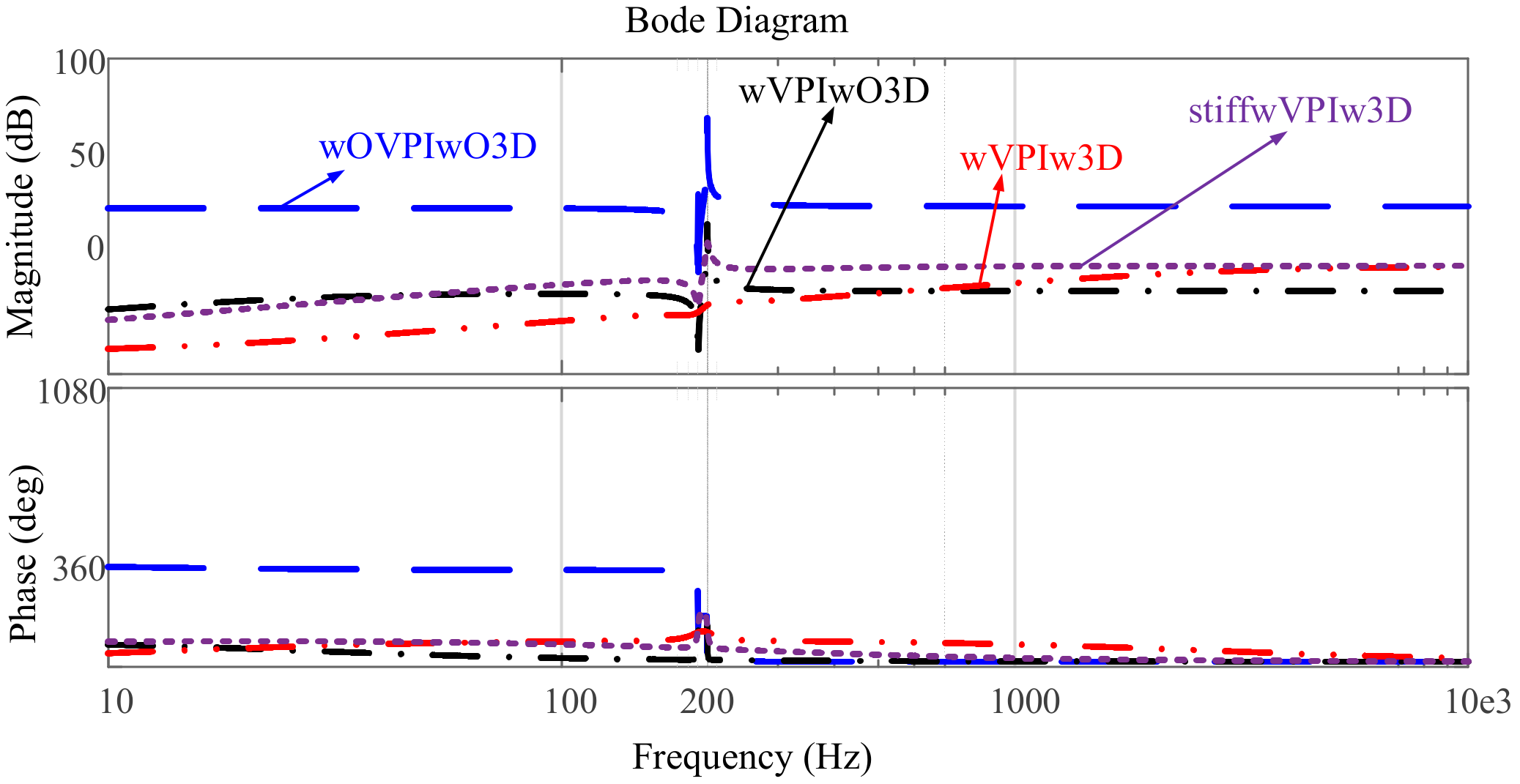
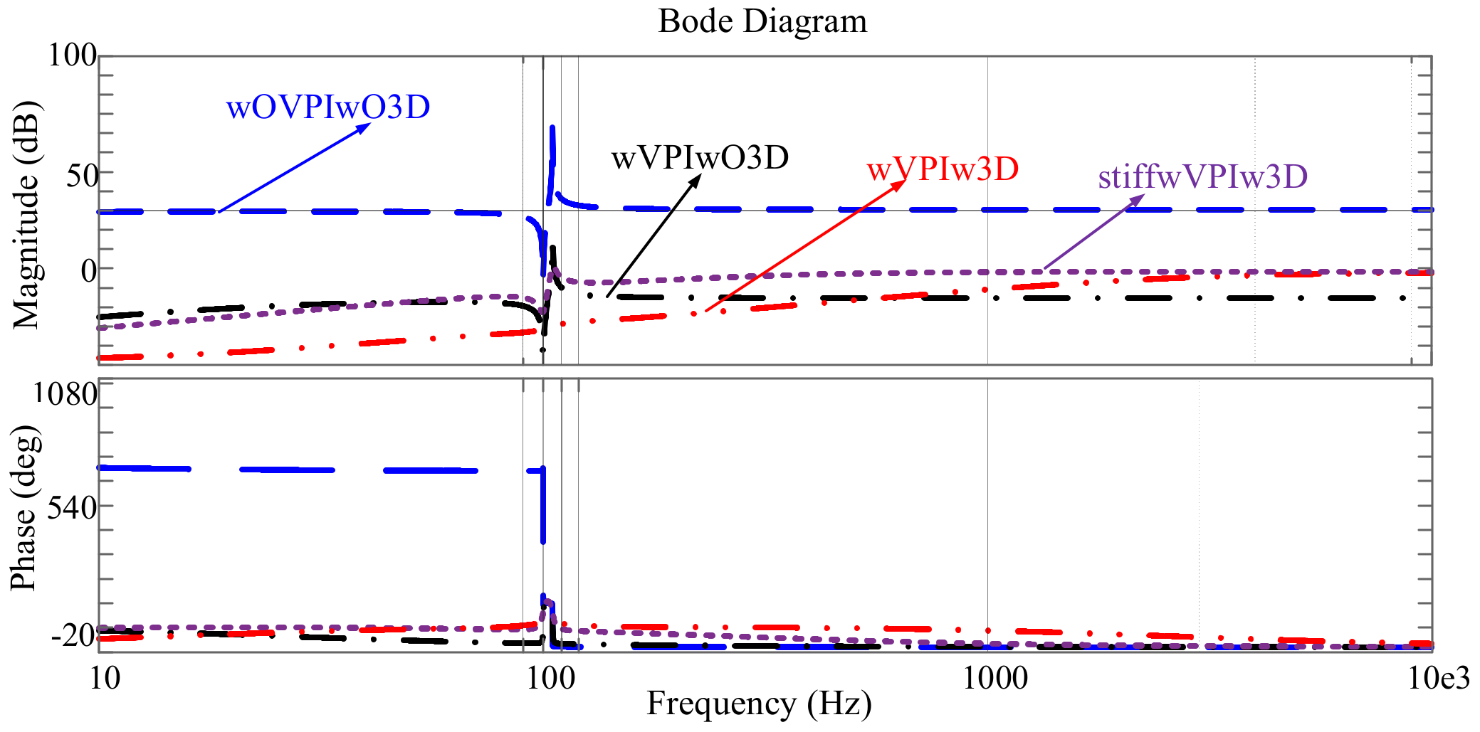
According to the Equation (18), bode diagrams of the 1/Yctrl at 1500 rpm and 3000 rpm are given in Figure 8 and Figure 9.
The Bode diagrams of the control impedance of the four cases can be seen at 1500 rpm and 3000 rpm. In the case of not using VPI based ADC and 3DSVPWM that is wOVPIwO3D (blue), the impedance magnitude behaves flat, but it does not reach zero. By contrast, in the case of the wVPIwO3D (black), wVPIw3D (red), and stiff wVPIw3D (purple), the magnitude of the control impedance becomes lower than that without active damping in the frequency range. The resonance is named as Negative-Impedance (NI) resonance due to the frequency character decided by NI at the constant power load (CPL) situation. Its impedance characteristic behaves as an inductive plus negative-resistive impedance during [10, 5000] Hz. This is helpful in suppressing the harmonics, caused by the resonance between Lgd and Cdc. In order to improve the THD (lower ripple on magnitude), impedance is increased at the current controller bandwidth. Increased impedance with the bandwidth of the current controller is helpful for suppressing the current harmonics (100 Hz and 200 Hz). Additionally, control impedance always behaves as positive-resistive plus inductive at high frequency while capacitive at low frequency. This positive-resistive characteristic helps to damp the system into a stable state.

4.1. The Performance Analysis of the DC-Link Voltage THD and the Motor Current THD

According to the VPI based ADC, the performance analysis of the DC-link voltage THD and the motor current THD is presented. Owing to the fact that the big size capacitor or RLC components have a higher cost and shorter lifetime, using the film capacitor as the slim DC-link capacitor in drivers can be a good alternative [
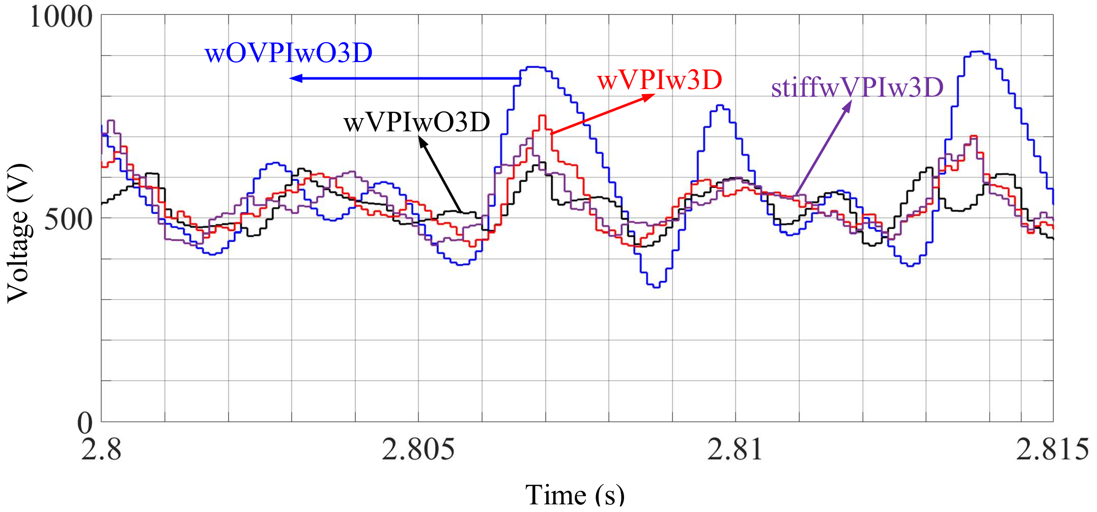
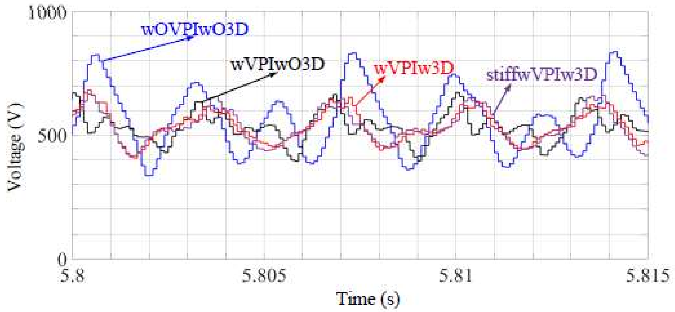
1]. In spite of the stability problem, the DC-link voltage of the slim capacitor is controlled well with VPI based ADC and 3DSVPWM. The DC-link voltage performances of the four cases are given below. The DC-link voltage when rotor speed is 1500 rpm is shown in Figure 10 and the DC-link voltage when rotor speed is 3000 rpm is shown in Figure 11. Firstly, the motor is operated at 1500 rpm from 0 s to 3 s, and then it is operated at 3000 rpm from 3 s to 6 s. However, time periods of the simulation are only 2.8–2.815 s and 5.8–5.815 s, because the results of the simulation are the same during 0s to 3 s and 3 s to 6 s. Thus, 2.8–2.815 s as TP1 (time period 1) and 5.8–5.815 as TP2 (time period 2) are used.
The ripples on the DC-link voltage when rotor speed is 1500 rpm and 3000 rpm are given in Table 2.
In addition, the fast Fourier transform (FFT) results of the DC-link voltage when rotor speed is 1500 rpm and 3000 rpm are given in Table 3.
As shown in Table 2, the case of stiffwVPIwO3D has the best performance, as expected, with the lowest ripples on the DC-link voltage for both operation speeds as 82.1 V and 76.79 V. However, wVPIwO3D with a weak grid has the best THD results for both operation speeds according to Table 3, as 13.15% at TP1 and 15.80% at TP2. Additionally, the ripples on DC-link voltage wVPIwO3D are obviously better than those on wVPIw3D (158.9–225.0 V and 144.2–169.6 V). The ripple on the DC-link voltage of the VPI based ADC with traditional SVPWM can oscillate. Lower ripples on DC-link voltage are obtained as 158.9 V at TP1 and 144.2 V at TP2. This means that using both the 3DSVPWM and the VPI based ADC does not provide better results of the ripple on DC-link voltage. Moreover, the FFT results of the motor current harmonics are displayed in Table 4.
From Table 4, the motor current harmonics of wVPIw3D with a weak grid or stiff grid are acceptable. When the 3DSVPWM is enabled, the motor current harmonics are suppressed effectively as 10.74% at TP1 and 12.07% at TP2 for Case 3 and 10.84% at TP1 and 11.95% at TP2 for Case 4.
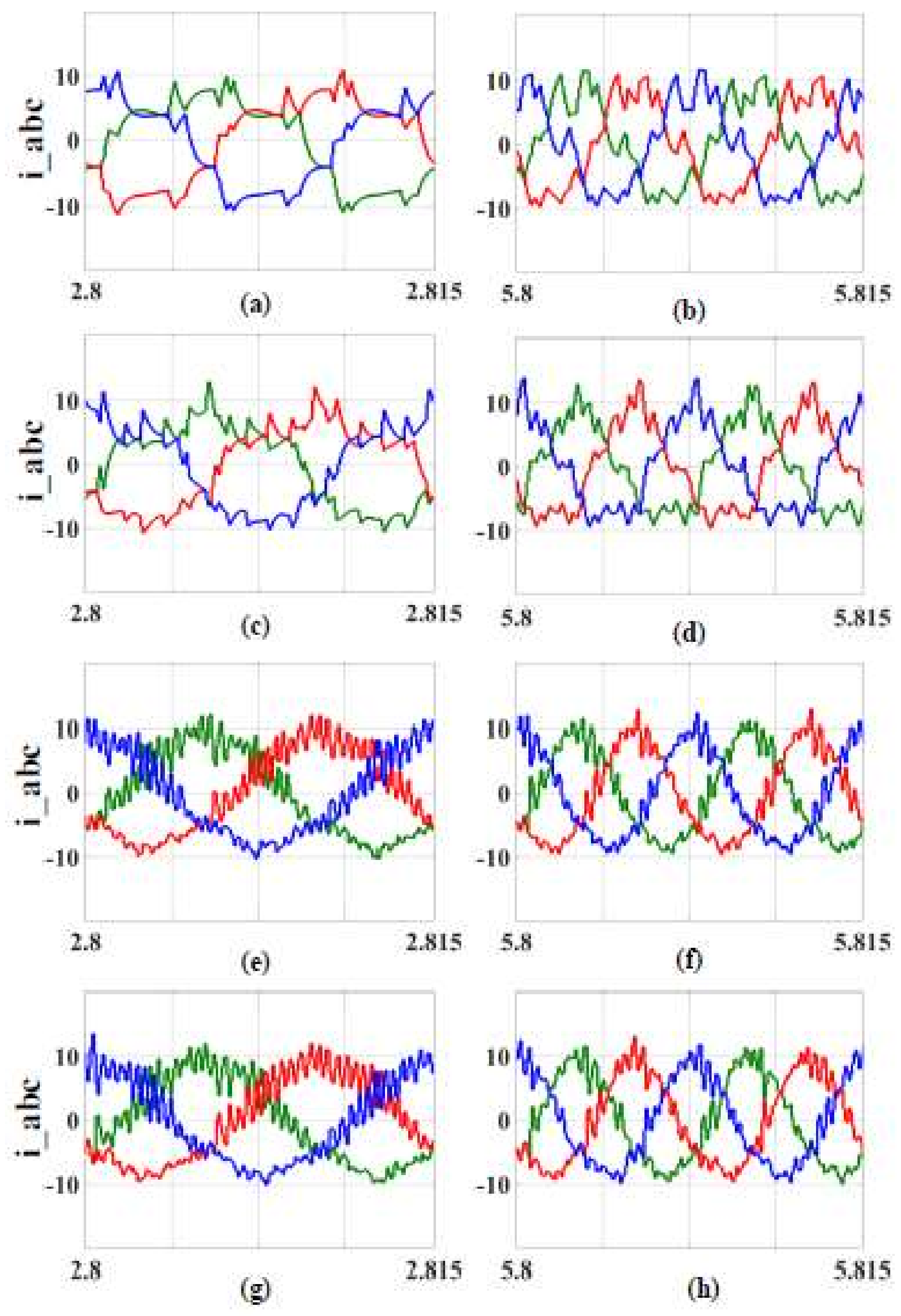
The motor current (i_abc) waveforms of 4 cases are given in Figure 12. As seen there, Case 4 supplies the best results (g and h), thanks to virtual positive impedance-based active damping control and 3DSVPWM under the stiff grid. Then, Case 3 gives good results (e and f), thanks to virtual positive impedance-based active damping control and 3DSVPWM under the weak grid. Motor currents without 3DSVPWM means are seen in Case 2 (c and d). Lastly, motor currents with classical SVPWM without VPI based ADC means (a and b) are given in Case 1.

4.2. The Performance Analysis of the Grid Current THD and the Cogging Torque

Table 5 shows the analysis of the grid current THD according to the four cases of simulation results.
As shown in Table 5, the grid input current FFT results are shown when the drive load is 3 kW. The FFT results of the grid input current of Case 1 are not as expected. When the 3DSVPWM is enabled, the THDi decreases from 51.60% to 43.88% at TP2, and it also decreases from 54.53% to 47.74% at TP1. Although Case 4 has a better result than Case 3 at 3000 rpm, the result of Case 4 gives worse THDi than Case 3 at 1500 rpm. The grid input current harmonics with the VPI based ADC and with the 3DSVPWM in Case 3 or Case 4 (with a weak grid or stiff grid) are acceptable. When the four cases are compared, the THDi results of Case 3 and Case 4 are rather desirable for both operation speeds.
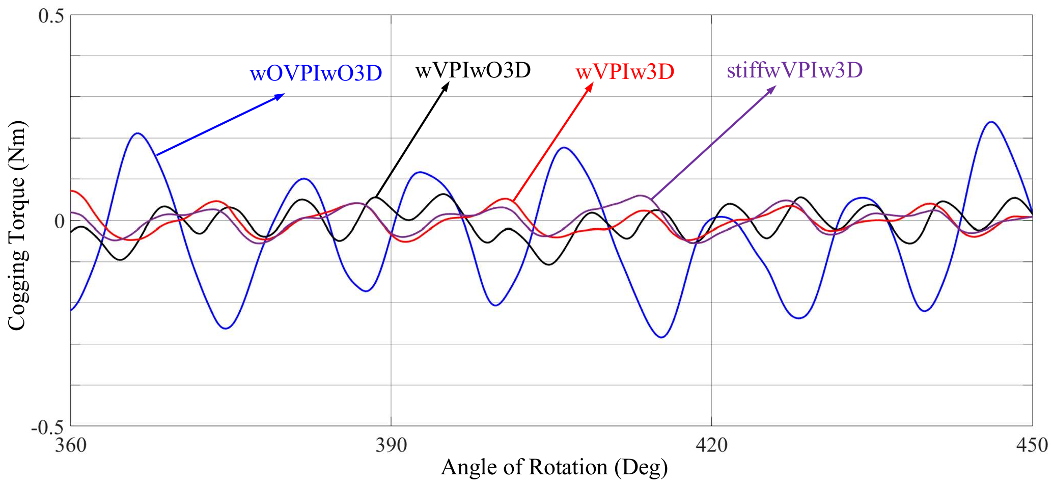
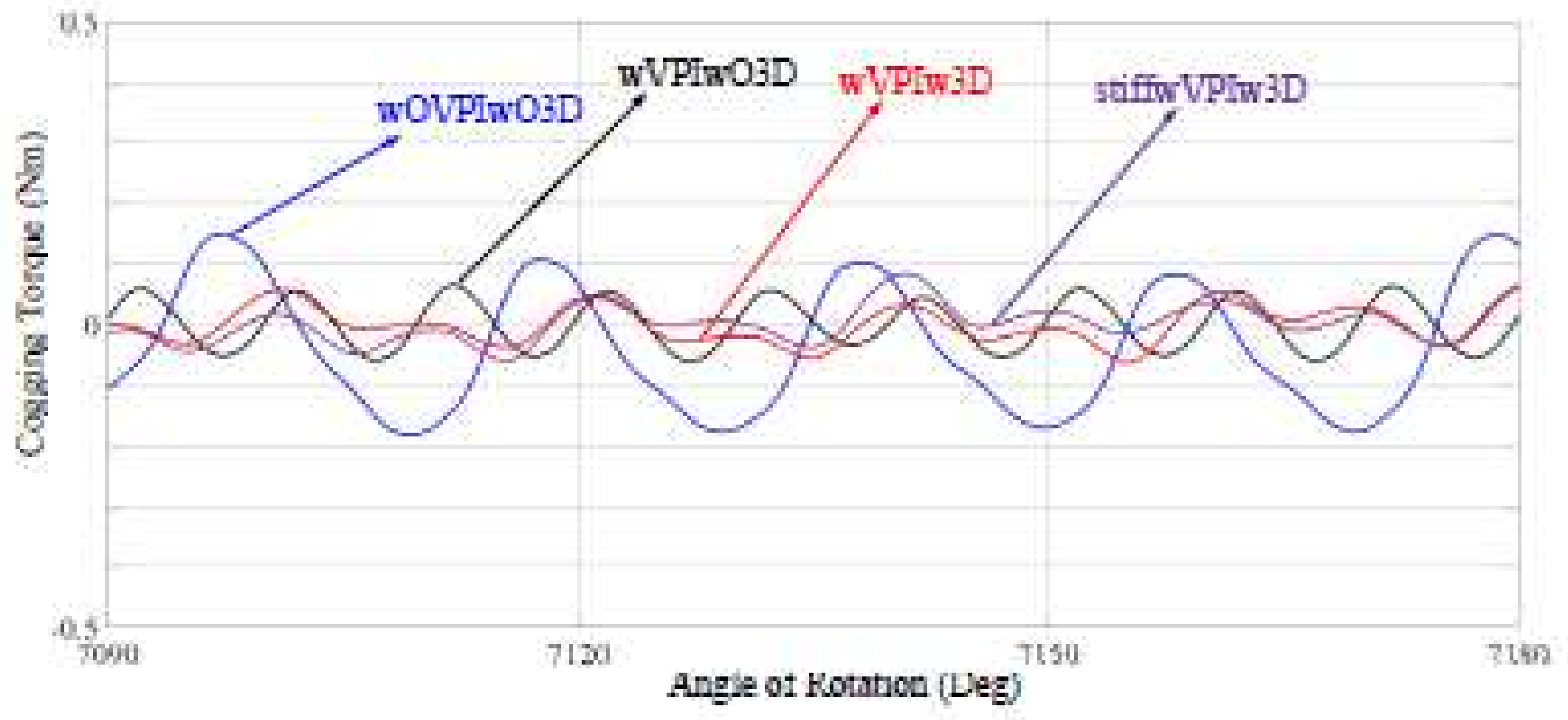
The cogging torque results are given in Table 6. As seen in Table 6, the cogging torque clearly decreases when adopting the 3DSVPWM. When Case 2 and Case 3 are compared, the cogging torque values get lower, from 0.25170 Nm to 0.15931 Nm at 3000 rpm and from 0.33270 Nm to 0.17871 Nm. Moreover, since the stiff grid is used, these results are 0.15285 Nm at 3000 rpm and 0.16720 Nm at 1500 rpm. In addition, the worst results are 0.28560 Nm at 3000 rpm and 0.44510 Nm at 1500 rpm from Case 1. These results are also seen in Figure 13 and Figure 14.
It can be seen that the cogging torque results are higher at a lower operation speed. The cogging torque results of Case 3 and Case 4 are more preferable than those of Case 1 and Case 2. Because the cogging torque is an important problem at low speed, the performance of the cogging torque in Case 3 and Case 4 are desired, especially at lower speed. At the same time, the cogging torque results of Case 3 and Case 4 at higher speed are better than those of the other cases. When both results in the tables and the figures are compared under either a weak or stiff grid, the adoption of the VPI based ADC and the 3DSVPWM together gives better results. The VPI based ADC ensures better harmonics, using a more advanced modulation technique, like 3DSVPWM (0.17871–0.15931 Nm and 0.16720–0.15285 Nm). Although the ripples on the DC-link voltage of the wVPIwO3D (Case 2) are lower without 3DSVPWM, the wVPIw3D (Case 3) and the stiffwVPIw3D (Case 4) are able to better suppress the grid current THD, the motor current THD, and the cogging torque.
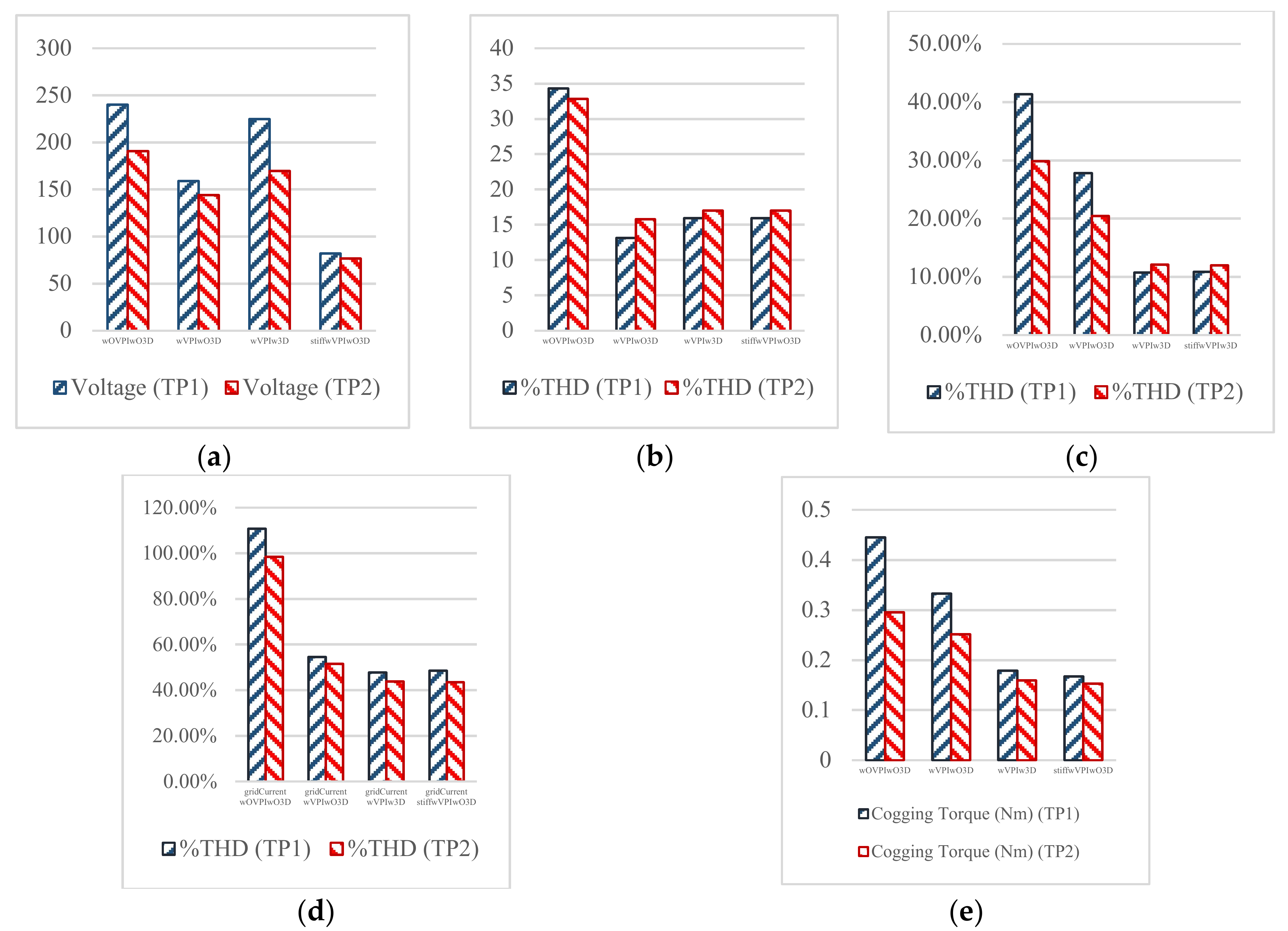
After the results are obtained, all of them are given in Figure 15.
The performance difference between cases is given in Figure 15. In this figure, the ripples of the DC-link voltage, the FFT results of the DC-link voltage, the FFT results of the motor current, the grid input current FFT results, and the cogging torque results are illustrated as bar graphics.

5. Conclusions

The motor drives equipped with the slim DC capacitor using the VPI based ADC and the 3DSVPWM are able to achieve lower input current harmonics and a lower cogging torque. In spite of the decreased ripples on DC-link voltages, the grid current harmonics and the motor current harmonics must be suppressed for the stable systems, because these harmonics result in a shorter lifetime for the driver and the cogging torque in the PMSM. However, a slim DC-link drive may not reach the expected performance, due to the weak grid condition. In this paper, the virtual positive impedance based active damping control and the 3DSVPWM are employed. Under either weak or stiff grid conditions, the four cases are clearly simulated. According to the simulation results, the performance of the VPI based ADC and the 3DSVPWM are investigated. In spite of the ripples on DC-link voltage, the 3DSVPWM with the VPI based ADC achieves harmonic suppression and a decreased cogging torque. Thus, a more stable and longer lifetime driver is obtained when the VPI based ADC and the 3DSVPWM are used.

Author Contributions

Conceptualization, F.B. and A.S.; Methodology, P.D; Software, A.A.; Validation, A.A., Y.S. and P.D.; Formal Analysis, A.A.; Investigation, P.D.; Resources, F.B. and P.D.; Data Curation, A.A.; Writing-Original Draft Preparation, A.A.; Writing-Review & Editing, P.D. and Y.S.; Visualization, Y.S.; Supervision, A.S. and F.B.; Project Administration, F. B. and A.S.; Funding Acquisition, A.S.

Funding

This research was funded by [TUBITAK] grant number [1059B141600864].

Conflicts of Interest

The authors declare no conflict of interest.

References

  1. Yang, F.; Mathe, L.; Lu, K.; Blaabjerg, F.; Wang, X.; Davari, P. Analysis of harmonics suppression by active damping control on multi slim dc-link drives. In Proceedings of the IEEE IECON 2016, Florence, Italy, 24–27 October 2016; pp. 5001–5006. [Google Scholar]
  2. Feng, Y.; Wang, D.; Blaabjerg, F.; Wang, X.; Davari, P.; Lu, K. Active damping control methods for three-phase slim DC-link drive system. In Proceedings of the IEEE IFEEC-ECCE 2017, Kaohsiung Taiwan, 3–7 June 2017; pp. 2165–2170. [Google Scholar]
  3. Soltani, H.; Davari, P.; Kumar, D.; Zare, F.; Blaabjerg, F. Effects of DC-link filter on harmonic and interharmonic generation in three-phase adjustable speed drive systems. In Proceedings of the IEEE ECCE 2017, Cincinnati, OH, USA, 1–5 October 2017; pp. 675–681. [Google Scholar]
  4. Maheshwari, R.; Munk-Nielsen, S.; Lu, K. An active damping technique for small dc-link capacitor based drive system. IEEE Trans. Ind. Inf. 2013, 9, 848–858. [Google Scholar] [CrossRef]
  5. Wang, D.; Lu, K.; Rasmussen, P.O.; Mathe, L.; Feng, Y. Analysis of voltage modulation based active damping techniques for small dc-link drive system. In Proceedings of the IEEE ECCE 2015, Montreal, CA, USA, 20–24 September 2015; pp. 20–24. [Google Scholar]
  6. Davari, P.; Yang, Y.; Zare, F.; Blaabjerg, F. A multi-pulse pattern modulation scheme for harmonic mitigation in three-phase multi-motor drives. IEEE J. Emerg. Sel. Top. Power Electron. 2016, 4, 174–185. [Google Scholar] [CrossRef]
  7. Hansen, S.; Nielsen, P.; Blaabjerg, F. Harmonic cancellation by mixing nonlinear single-phase and three-phase loads. IEEE Trans. Ind. Appl. 2000, 36, 152–159. [Google Scholar] [CrossRef]
  8. Malinowski, M.; Kazmierkowski, M.P.; Hansen, S.; Blaabjerg, F.; Marques, G.D. Virtual-flux-based direct power control of three-phase PWM rectifiers. IEEE Trans. Ind. Appl. 2001, 37, 1019–1027. [Google Scholar] [CrossRef]
  9. Kerem, A.; Aksoz, A.; Saygin, A.; Yilmaz, E.N. Smart grid integration of micro hybrid power system using 6-switched 3-level inverter. In Proceedings of the IEEE ICSG 2017, Istanbul, Turkey, 19–21 April 2017; pp. 161–165. [Google Scholar]
  10. Erol, C.; Sayan, H.H. A novel SSPWM controlling inverter running nonlinear device. Electr. Eng. 2018, 100, 39–46. [Google Scholar]
  11. Vafakhah, B.; Salmon, J.; Knight, A.M. A New Space-Vector PWM with Optimal Switching Selection for Multilevel Coupled Inductor Inverters. IEEE Trans. Ind. Electron. 2010, 57, 2354–2364. [Google Scholar] [CrossRef]
  12. Wang, Z.; Wang, Y.; Chen, J.; Hu, Y. Decoupled Vector Space Decomposition Based Space Vector Modulation for Dual Three-Phase Three-Level Motor Drives. IEEE Trans. Power Electron. 2018, 33, 10683–10697. [Google Scholar] [CrossRef]
  13. Song, J.Y.; Kang, K.J.; Kang, C.H.; Jang, G.H. Cogging Torque and Unbalanced Magnetic Pull Due to Simultaneous Existence of Dynamic and Static Eccentricities and Uneven Magnetization in Permanent Magnet Motors. IEEE Trans. Mag. 2017, 53, 1–9. [Google Scholar] [CrossRef]
  14. Yang, Y.; Zhou, K.; Wang, H.; Blaabjerg, F. Analysis and Mitigation of Dead Time Harmonics in the Single-Phase Full-Bridge PWM Converters with Repetitive Controllers. IEEE Trans. Ind. Appl. 2018. [Google Scholar] [CrossRef]
  15. Perez-Basante, A.; Ceballos, S.; Konstantinou, G.; Pou, J.; Kortabarria, I.; de Alegria, I.M. A Universal Formulation for Multilevel Selective Harmonic Elimination—PWM with Half-Wave Symmetry. IEEE Trans. Power Electron. 2018, 1. [Google Scholar] [CrossRef]
  16. Lee, J.S.; Kwak, R.; Lee, K.B. Novel Discontinuous PWM Method for a Single-Phase Three-Level Neutral Point Clamped Inverter with Efficiency Improvement and Harmonic Reduction. IEEE Trans. Power Electron. 2018, 33, 9253–9266. [Google Scholar] [CrossRef]
  17. Flankl, M.; Tüysüz, A.; Kolar, J.W. Cogging Torque Shape Optimization of an Integrated Generator for Electromechanical Energy Harvesting. IEEE Trans. Ind. Electron. 2017, 64, 9806–9814. [Google Scholar] [CrossRef]
  18. Holmes, D.G.; Lipo, T.A. Pulse Width Modulation for Power Converters; IEEE Press: Piscataway, NJ, USA, 2003. [Google Scholar]
  19. Celanovic, N.; Boroyevich, D. A fast space-vector modulation algorithm for multilevel three-phase converters. IEEE Trans. Ind. Appl. 2001, 37, 637–641. [Google Scholar] [CrossRef]
Figure 1. Diode rectified slim DC-link drive.
Electronics 07 00234 g001
Figure 2. PCC phase current. (a) Stiff grid at 1500 rpm. (b) Weak grid at 1500 rpm. (c) Stiff grid at 3000 rpm. (d) Weak grid at 3000 rpm.
Electronics 07 00234 g002
Figure 3. Virtual positive impedance block diagram [1].
Electronics 07 00234 g003
Figure 4. Reducing cogging torque schema [17].
Electronics 07 00234 g004
Figure 5. Space vector diagram of 3DSVPWM in 2D and 3D vectors after 3D transformation.
Electronics 07 00234 g005
Figure 6. Simplified equivalent DC-link in a drive unit.
Electronics 07 00234 g006
Figure 7. Control system block diagram with Virtual Positive Impedance (VPI) based active damping control (ADC).
Electronics 07 00234 g007
Figure 8. Bode plot of 1/Yctrl at 1500 rpm (Blue: wOVPIwO3D. Black: wVPIwO3D. Red: wVPIw3D. Purple: stiffwVPIwO3D).
Electronics 07 00234 g008
Figure 9. Bode plot of 1/Yctrl at 3000 rpm (Blue: wOVPIwO3D. Black: wVPIwO3D. Red: wVPIw3D. Purple: stiffwVPIwO3D).
Electronics 07 00234 g009
Figure 10. DC-link voltage when rotor speed is 1500 rpm.
Electronics 07 00234 g010
Figure 11. DC-link voltage when rotor speed is 3000 rpm.
Electronics 07 00234 g011
Figure 12. Motor current waveforms. (a) wOVPIwO3D at TP1. (b) wOVPIwO3D at TP2. (c) wVPIwO3D at TP1. (d) wVPIwO3D at TP2. (e) wVPIw3D at TP1. (f) wVPIw3D at TP2. (g) stiffwVPIw3D at TP1. (h) stiffwVPIw3D at TP2.
Electronics 07 00234 g012
Figure 13. Cogging torque at 1500 rpm.
Electronics 07 00234 g013
Figure 14. Cogging torque at 3000 rpm.
Electronics 07 00234 g014
Figure 15. The performance difference between cases. (a) The ripples of the DC-link voltage. (b) The FFT results of the DC-link voltage. (c) The FFT results of the motor current. (d) The grid input current FFT results. (e) Cogging torque results.
Electronics 07 00234 g015
Table 1. The parameters of the drive and the PMSM.
ParametersValues
Vrms400 V/3 ph
Cdc14 uF
SCR (weak grid-stiff grid)35–350
Ts50 us
Tm4 Nm
R150 mΩ
LdLq8.5–8.8 mH
ωr1500–3000 rpm
Table 2. The ripples of the DC-link voltage.
CasesVoltage (TP1)Voltage (TP2)
wOVPIwO3D240.3190.8
wVPIwO3D158.9144.2
wVPIw3D225.0169.6
stiffwVPIwO3D82.176.79
Table 3. The FFT results of the DC-link voltage.
CasesTHD% (TP1)THD% (TP2)
wOVPIwO3D34.3432.84
wVPIwO3D13.1515.80
wVPIw3D15.9317.01
stiffwVPIwO3D15.9317.02
Table 4. The FFT results of the motor current.
CasesTHD% (TP1)THD% (TP2)
wOVPIwO3D41.36%29.82%
wVPIwO3D27.83%20.46%
wVPIw3D10.74%12.07%
stiffwVPIw3D10.84%11.95%
Table 5. The grid input current FFT results.
CasesTHD% (TP1)THD% (TP2)
gridCurrent wOVPIwO3D110.71%98.45%
gridCurrent wVPIwO3D54.53%51.60%
gridCurrent wVPIw3D47.74%43.88%
gridCurrent stiffwVPIwO3D48.60%43.48%
Table 6. The cogging torque results.
Cogging Torque (Nm) (TP1)Cogging Torque (Nm) (TP2)
wOVPIwO3D0.445100.29560
wVPIwO3D0.332700.25170
wVPIw3D0.178710.15931
stiffwVPIwO3D0.167200.15285

