Article

Synchronous Reference Frame Repetitive Control of a Single-Phase Three-Level Dual-Buck Photovoltaic Inverter

Department of Electrical and Electronics Engineering, Konkuk University, Seoul 05029, Korea
*
Author to whom correspondence should be addressed.
Electronics 2018, 7(10), 226; https://doi.org/10.3390/electronics7100226
Submission received: 12 September 2018 / Revised: 26 September 2018 / Accepted: 27 September 2018 / Published: 2 October 2018
(This article belongs to the Special Issue Renewable Electric Energy Systems)

Abstract

:
This paper proposes a synchronous reference frame (SRF) control strategy for a single-phase, three-level, dual-buck photovoltaic (PV) inverter. The concept of virtual d-q transformation is adapted to the current control of the inverter, and the repetitive controller is implemented in the SRF. With the proposed control strategy, the memory allocation quantity for the repetitive controller is decreased and the capability of the current reference tracking is maximized. Thus, the proposed method significantly reduces the total harmonic distortion (THD) of the output current in both the continuous conduction mode (CCM) and the discontinuous conduction mode (DCM). In addition, the distortion of the output current is mostly composed of odd harmonics. Odd harmonic expressed to the even harmonic in SRF can be calculated using Park’s transformation. Therefore, a repetitive controller can improve dynamics by considering only even harmonic components in SRF rather than including all harmonics. The simulation and the experimental results verify the effectiveness of the proposed control strategy. The proposed method not only reduces the THD of the output current in both the CCM operation and the DCM operation, but also improves the dynamics of the current controller.

1. Introduction

Greenhouse effects and atmosphere pollution problems caused by conventional power generation are becoming severe [1,2]. To solve these issues, many studies have been conducted on electric power generation using renewable energy such as photovoltaic (PV), wind power, and so on. In particular, PV power generation systems have achieved impressive growth compared with other renewable energy sources. Hence, installations of PV power systems go on increasing year by year [3].
Grid-connected PV systems account for a large portion of the total PV system installation [4]. Grid-connected PV systems are classified into two types depending on the presence or absence of a transformer between the PV module and the utility grid. The transformer-less systems are preferred for low power, single-phase PV applications in practice. This is because they usually improve the power density and efficiency compared with the PV inverter with transformer [5]. However, the leakage current can be increased compared with the PV inverters with a decoupling transformer because of the stray capacitor between the PV module and the utility grid. As the common mode voltage fluctuated, the stray capacitance charges and discharges repeatedly, resulting in high leakage currents [5,6]. Such a leakage current can be eliminated or reduced depending on the control strategies or topologies [7,8,9,10,11,12,13,14,15].
Among various topology solutions, dual-buck inverters (DBI) have been considered as a promising circuit structure to achieve a high efficiency and low leakage current without significant engineering efforts [6,16,17]. The switching modulation method of the DBI is characterized by Sp and S1 in positive and Sn and S2 in negative depending on the polarity of the grid voltage. A detailed description of the modulation and current path can be found in the work of [16]. According to the current path, the voltage on stray capacitor between the PV array and the grid changes with the grid frequency. Therefore, the voltage of the stray capacitor becomes constant during the half cycle of the grid frequency, and the leakage current is restrained [18]. The DBI performs a similar operation to the buck converter at each polarity of the utility grid. The DBI outputs unipolar pole voltage at each grid polarity as the switches S1 and S2 operate independently. Therefore, the output current under the light load has severe current distortions as it cannot flow in an opposite direction [16].
The distortion caused by unidirectional and control performance of the current is highly dependent on the controller structure. Regarding this issue, many control strategies have been studied including predictive controllers and modulations. The proportional integral (PI) controller, which is traditionally used in the industry, is easy to implement and simple in structure. For the system operating at fixed frequencies of 60 Hz or 50 Hz, using a PI controller has poor stability and control performance. To overcome this disadvantage, a proportional resonant (PR) controller is used to maximize the performance for a specific frequency. The PR controller is optimized for grid-connected systems because it has high gain at a certain frequency. As the PR controller optimized in a specific frequency, the other compensator like a repetitive controller should be added to control other frequency components. This paper proposes the synchronous reference frame (SRF) PI controller with repetitive current control strategy for dual-buck PV inverters. Using the proposed method, the current distortion caused by the discontinuous conduction mode (DCM) operation of the inverter under light load conditions can be dramatically compensated. Also, by controlling the current in the SRF, the output current is converted into the DC component and the PI controller works effectively. Because of the proper operation of the proposed control strategy, the dynamic property of current control is much faster than the stationary reference frame repetitive controller.
This paper is organized as follows. In Section 2, the topology and the operation of the dual-buck inverter are described. The investigation of the modeling equation and the transfer function of the DBI is conducted. Both the stationary reference frame and the SRF will be discussed for the modeling equations. Furthermore, the loop-gain of the entire control system is evaluated using the derived transfer function for convincing the proposed and designed controller. Section 3 provides the proposed control structure including the design of the proposed repetitive controller. The simulation and experimental results are shown in Section 4. Finally, the conclusion is made in Section 5 to summarize the results of this work.

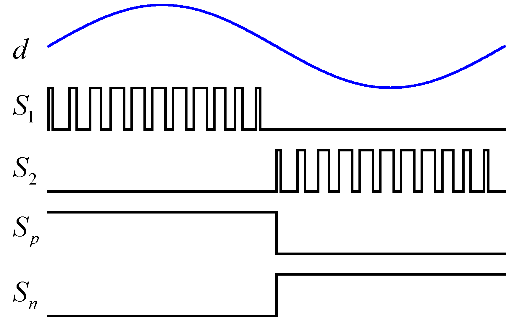
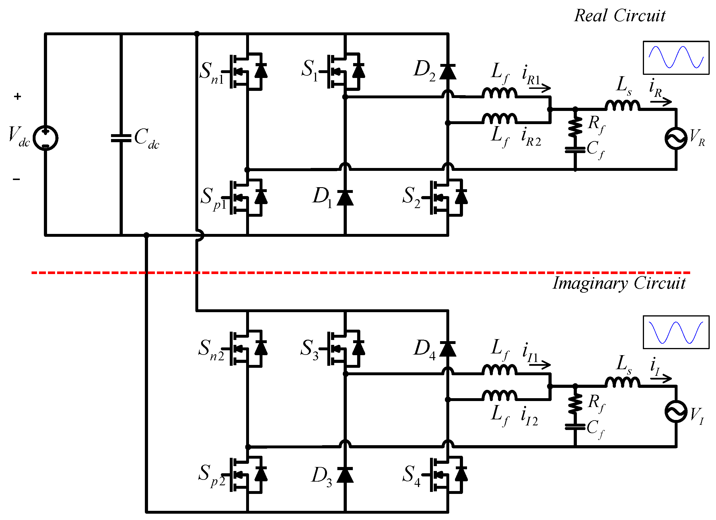
2. Circuit Structure and Control Strategy of DBI

Figure 1 shows the circuit structure of the three-level dual-buck PV inverter. In order to reduce the power stage loss, the dc-link is directly fed by the PV panel with the blocking diode. As the maximum power point tracking (MPPT) performance is necessary, the dc-link voltage is indirectly regulated by controlling the output power of the inverter at the given irradiation conditions. The LCL filter with the damping resistor Rf is composed of the inverter- and grid-side inductors, Lf and Ls, and the filter capacitor Cf. Unlike traditional full-bridge inverters, the three-level dual-buck inverter has two switching stages that operate with the low and high frequency. In the figure, the pair of the switches Sp and Sn operates at grid switching frequency and the other pair of switches S1 and S2 operates at high switching frequency. The main role of low frequency switching side switches is to determine the polarity of the output voltage. The switches that operate at the high frequency switching side regulate the magnitude of the grid current. By considering this, the modulation signals of the three-level dual-buck inverter [16] are represented as illustrated in Figure 2.
Compared with traditional full-bridge inverters, the three-level dual-buck inverter achieves very high efficiency. In addition, it is also attractive that the ground leakage current can be significantly reduced. Further analysis about the DBI can be found in the literature [16,17].
Similarly to other PV inverters, various current control strategies can be adapted in DBI. One simple approach is implementing the current controller in the stationary reference frame, where the control states and variables turn up in ac components at the steady-states. In this approach, the realization of the current controller is straight-forward, and many single-phase systems employ this strategy. One trouble of this method is that the steady-state error can exist due to the characteristics of the stationary current control, where the phase delay is induced in the current control loop-gain. To mitigate the defects, SRF based current control strategies in single-phase systems have been studied. The virtual d–q transformation is one of the useful approaches to implement the SRF in single-phase systems. The fundamental component of the controlled current is shown as a dc value at steady-states [19,20]. Therefore, the control performance including the reference tracking and the adjustable phase function can be significantly improved. It can be also considered as a control of a simple dc–dc converter, because the operating point is fixed at a certain point. In theory, the steady-state error can be perfectly eliminated due to the infinity loop-gain with a simple proportional-integral (PI) controller in the SRF [21,22,23,24].

2.1. DQ Rotating Frame Concept

In single-phase systems, the adaptation of d–q transformation is not available without a special technique, because there is no quadrature axis with respect to the original axis that can be considered as a direct axis. Hence, an additional virtual phase is necessary. This means the virtual phase that is orthogonal to the original phase should be artificially created. To do this, an all pass filter (APF) whose critical frequency corresponds to the operating frequency of the original phase has been adapted in this paper. By using the APF, the virtual quadrature current whose phase is lagged by π/2 rad compared with the original one is produced. The transfer function of the APF is defined as follows:
G a p f ( s ) = s ω s + ω
where ω is the angular velocity of the utility grid obtained by phase locked loop (PLL) [25]. By implementing (1) in the time domain and multiplying with the grid current is, the virtual quadrature current iI is simply obtained. Then, the phase of iI is delayed by π/2 rad. Once is and iI are obtained, the currents in the SRF, id and iq, are calculated using (2).
[ i d i q ] = [ cos ω t sin ω t sin ω t cos ω t ] [ i s i I ]
It should be noticed that id and iq should be dc components at the steady-states, while is and iI are ac ones. Accordingly, the control variables are not ac currents, but dc components.

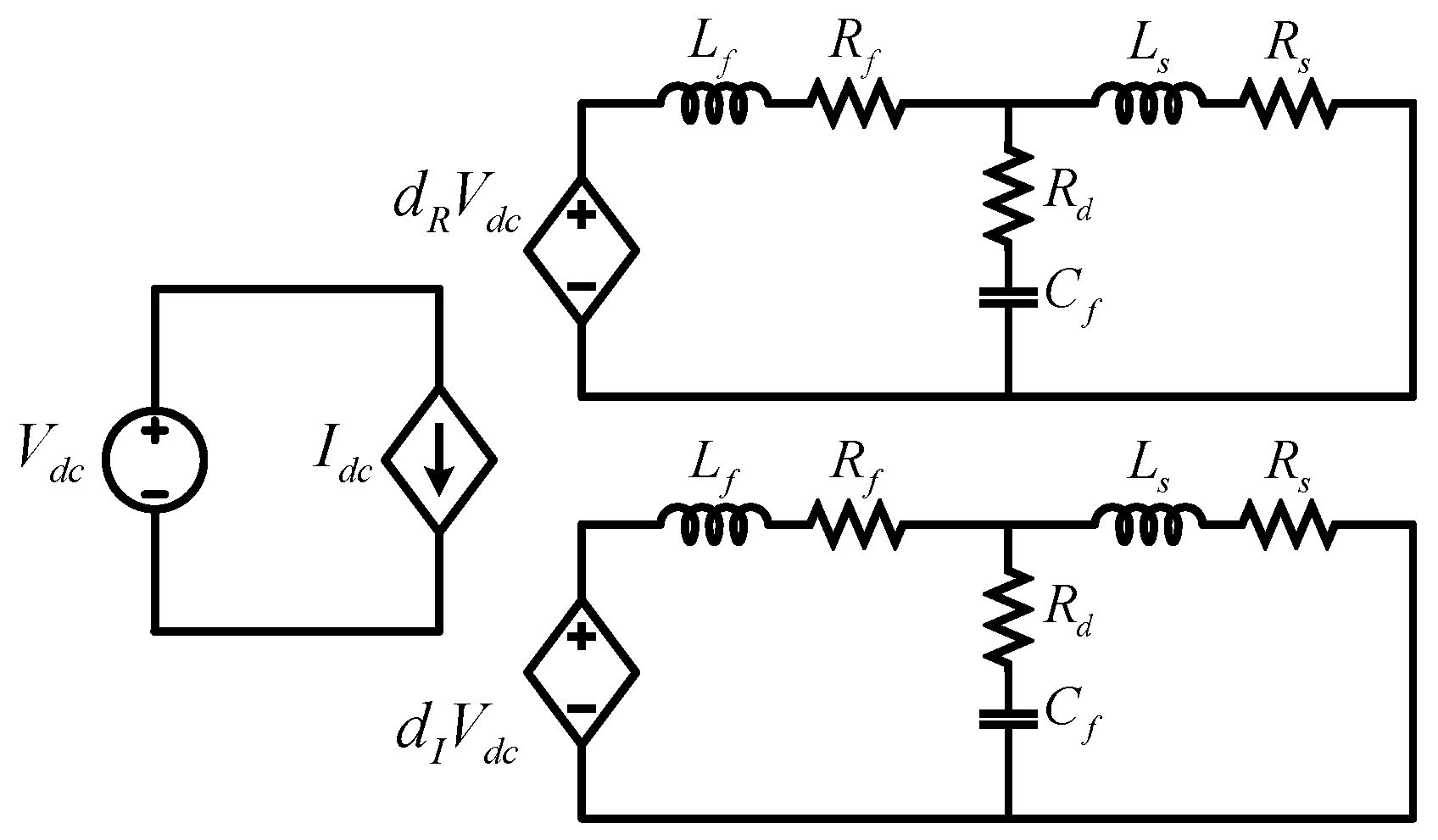
2.2. Average and DQ Models of the Single Phase DBI

Because only one phase is existent in single-phase systems, a virtual quadrature circuit is necessary to implement dq transformation [25]. Figure 3 represents the fundamental concept of the real and virtual quadrature circuits. For the virtual quadrature circuit, the circuit structure and all components including the switching devices, inductors, and capacitors are identical to the original circuit for the fundamental frequency, except that there are π/2 rad differences between the original and virtual quadrature voltage and currents. For harmonic components, the parameters of the circuit components are different.
Figure 4 shows the average models of the practical and virtual quadrature circuits. The meaning of the dR and dI is duty on the real and imaginary orthogonal circuit, respectively. Here, the LCL filters are composed by Lf, Rf, Ls, and Cf, and the damping resistance Rd are to filter out the high frequency components of the output current.
In this configuration, the Cf is small enough to be ignored for modeling the system feature, so that it can be omitted in the grid current equations below. Consequently, the grid current equations can be rewritten as follows:
d d t i R I = V d c L d R I R L i R I
where parameters L, R, and dRI represent Ls + Lf, Rs + Rf, and the duty cycles in the practical and the virtual reference frame. It should be noticed that the practical variables iR and dR can be represented as isd and dsd, while the virtual variables iI and dI are modeled as isq and dsq in the stationary reference frame. By considering this, (3) can be written as (4) in the stationary reference frame.
d d t [ i d s i q s ] = V d c L [ d d s d q s ] R L [ i d s i q s ]
In order to obtain the equations in SRF, the transformation matrix T as represented in (6) is applied in (4) as shown in (5).
d d t { T 1 [ i d i q ] } = V d c L T 1 [ d d d q ] R L T 1 [ i d i q ]
where T is defined as below:
T = [ cos θ sin θ 0 sin θ cos θ 0 0 0 1 ]
where θ is the phase angle of the utility grid.
By developing (5) using the inverse matrix of T, the d–q current components in the SRF are obtained as shown in (7).
d d t [ i d i q ] = V d c L [ d d d q ] R L [ i d i q ] + ω [ i q i d ]
In (7), the coupled terms iq and id are existent in the d- and q-axis. It has been well-known that these coupled terms deteriorate transient responses. As the parasitic resistance Rs and Rf of the filter inductor Ls and Lf are small enough not to affect the plant transfer function [16]. Therefore, Equation (7) can be expressed simply as follows:
d d t [ i d i q ] = V d c L [ d d d q ] + ω [ i q i d ]

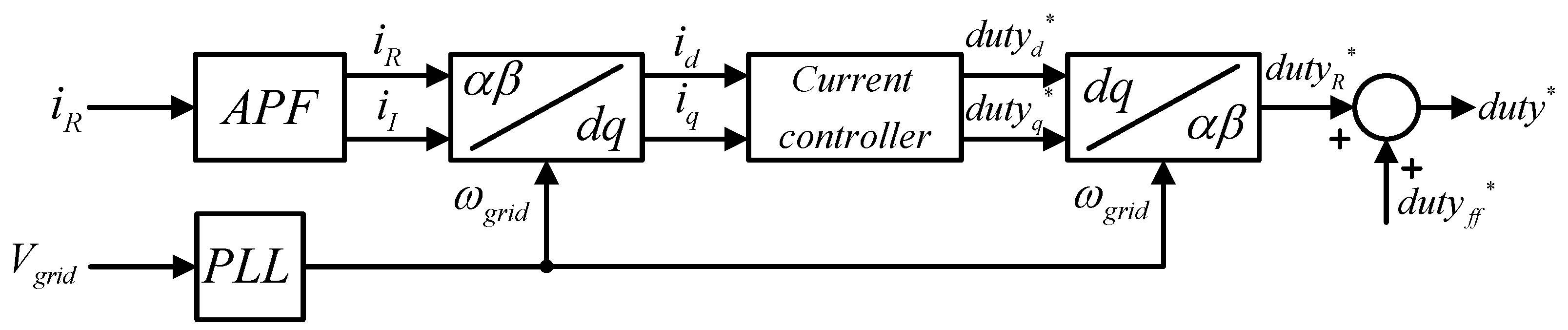
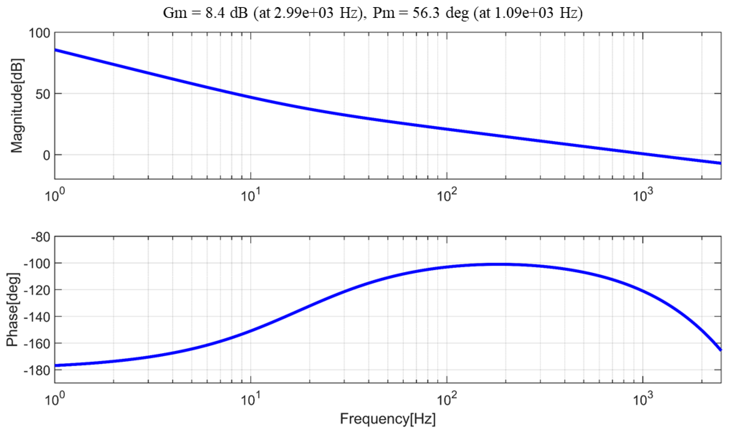
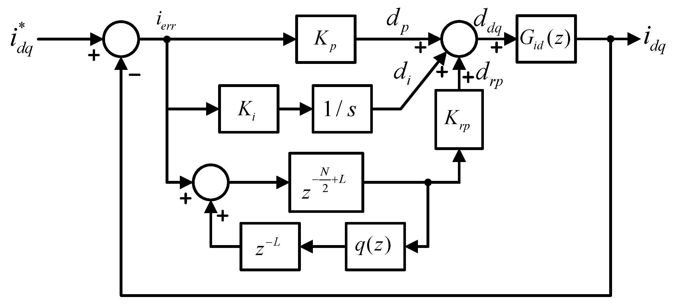
2.3. d–q Current Controller Design

The d–q current control structure of the single DBI is shown in Figure 5. The output duty reference of the current controller and the feed-forward are added together to control the DBI system. In order to compensate the disturbance arising from the utility grid voltage, the feed-forward term generate a duty reference as follows:
d f f = V g r i d V d c
where Vgrid is utility grid voltage and Vdc is dc-link voltage. With the feed-forward, loop-gain analysis becomes possible without considering grid disturbance. Consequently, the influence on grid is omitted in DBI system modeling.
In the stationary reference frame, the proportional resonant (PR) controller is used rather than the proportional integral (PI) controller so as to secure a high gain in fundamental frequency component. However, as mentioned in the previous section, the PI controller on SRF has a very large gain on fundamental frequency. This paper proposes a control scheme that integrates a PI controller with a repetitive controller for compensating current distortion and an effective current controller. The proposed current control strategy is illustrated in Figure 6.
Generally, the grid-connected inverters mainly undergo the output current distortion containing odd harmonics. In order to compensate the harmonics, the loop-gain of the current controller should have extremely high gains at individual harmonic bands. With traditional proportional-integral (PI) control approaches, it is very hard to satisfy the conditions above in wide frequency ranges [26]. In this view points, the use of repetitive controllers is a very good solution to achieve the output current with a very low total harmonic distortions (THD). Repetitive controllers are based on internal model principle [27,28,29]. Hence, if the periodic errors are continuously repeated, the reference tracking performance can be excellent with very high accuracy in the closed-loop control system. Because of this feature, a repetitive controller is paralleled to the traditional PI controller to reduce the steady-state error [30].
In order to keep the DBI control stable, the proposed controller that composed with PI and repetitive controller must be optimized. The contents of the repetitive controller design are covered in detail in the next section. The loop-gain considering only the PI controller on SRF is derived as follows:
G p i ( s ) G i d ( s ) = ( K p + K i s ) ( V d c s ( L s + L f ) )
where the transfer function of the PI controller is Gpi(s) and Gid(s) is the system transfer function, respectively.
In addition, the transfer function considering the digital computation is calculated as follows:
G p i ( z ) G i d ( z ) = ( K p + K i T s z 1 ) ( V d c T s ( L f + L s ) z ( z 1 ) )
Equation (11) also takes into account the unit delay caused by the digital control. The bode plot of the designed PI controller is shown in Figure 7. From the result of the frequency response curve, the bandwidth is 1.09 kHz and the phase margin is 56.3 deg. The gain of PI controller, which consisted with Kp and Ki, had been selected as 0.018 and 2, respectively.

3. Even Harmonics Repetitive Controller Design

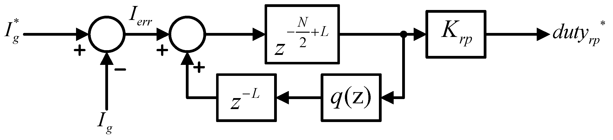
3.1. Even Harmonics Repetitive Controller

As shown in Figure 6, the repetitive controller is paralleled with the traditional PI controller. The repetitive controller has infinite poles at the harmonic frequencies, so that the steady-state periodic error can be perfectly compensated. In order to design an optimized repetitive controller in the SRF, some analyses are performed below. In fact, the grid current mainly contains odd harmonic components. The odd harmonics in the grid current is converted to corresponding even harmonics in the SRF. Equation (12) clearly describes this fact. When odd harmonic currents, Iacos((2k + 1)ωt) and Ibsin((2k + 1)ωt), in the stationary reference frame are converted into SRF, the results are the even harmonic currents, id(2k) and iq(2k), as can be seen in (12):
[ i d ( 2 k ) i q ( 2 k ) ] = [ cos ω t sin ω t sin ω t cos ω t ] [ I a cos ( ( 2 k + 1 ) ω t ) I b sin ( ( 2 k + 1 ) ω t ) ] = [ I a cos ( 2 k ω t ) I b sin ( 2 k ω t ) ]
where k is the harmonic order index.
According to (12), it is recognized that the repetitive controller in the SRF should mainly compensate even harmonics. Figure 8 shows the even harmonic repetitive control scheme applied in this paper [31,32]. The design of the even harmonic repetitive control scheme should not be much different from that of the original repetitive controller [29]. The proposed repetitive controller is configured as the repetitive control gain Krp, the number of samples N, the number of samples for the phase leading L, and the stabilization filter q(z). The number of samples during one period of the fundamental frequency is defined as follows:
N = 1 f × T s
where f and Ts are the fundamental frequency and the sampling period, respectively. When the fundamental frequency is doubled, the number of samples is obtained as N/2 according to Equation (13).
Next, the phase leading factor L is chosen by considering the stability improvement and the propagation delay. The factor L is selected as 2, considering the digital computation and modulation delays, 1.5 Ts.
The main purpose of the stabilization filter is to reduce the high frequency components, which cannot be compensated in physical without phase delay. For this purpose, a zero-phase delay low pass filter shown in (14) is employed [33,34].
q ( z ) = 0.25 z 1 + 0.5 + 0.25 z
Using (14), the entire stability of the repetitive control system can be significantly improved.

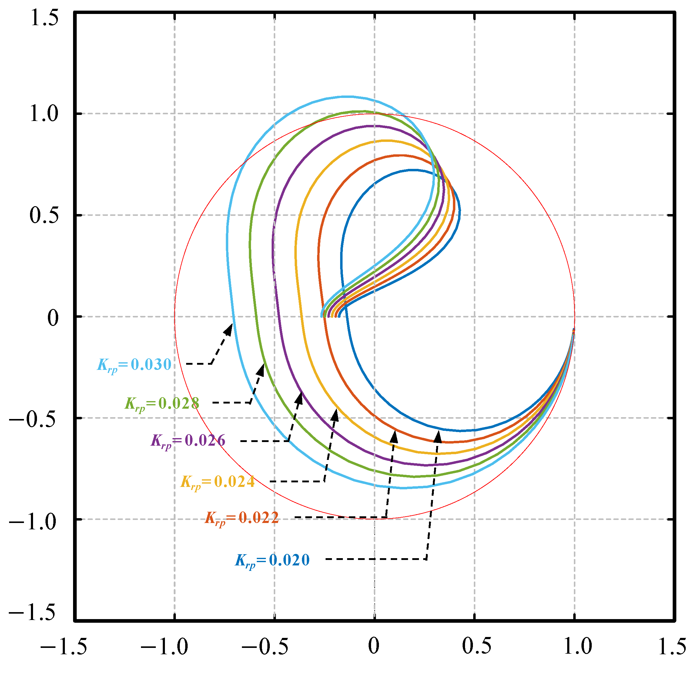
3.2. Repetitive Controller Design

If the cross coupling term is decoupled as shown in Figure 6, the general expression of the control scheme with the proposed repetitive controller can be drawn as in Figure 9. Therefore, the gain of the dq current controller can be selected equally. From Figure 9, the transfer function of the repetitive controller Grp(z) defined as (15).
G r p ( z ) = d r p i e r r = K r p z L z N / 2 q ( z )
The error transfer function Gie(z) is also obtained as follows:
G i e ( z ) = i e r r i d q * = G e p i ( z ) G e r p ( z )
where Gepi(z) and Gerp(z) are defined as follows:
G e p i ( z ) = 1 1 + ( K p + K i T s z 1 ) G i d ( z ) = 1 1 + G p i ( z ) G i d ( z )
G e r p ( z ) = z N q ( z ) z N H ( z )
In (18), H(z) is defined as follows:
H ( z ) = q ( z ) K r p z L G i d ( z ) 1 + G p i ( z ) G i d ( z )
To stabilize the loop-gain of the proposed control scheme, both Gepi(z) and Gerp(z) must be stable. This can be easily analyzed by using the unit circle concept in the discrete time domain. In fact, Gepi(z) is also affected by Kp and Ki. The PI gains are designed by considering the required bandwidth and the phase margin as explained in the previous section.
The stability of Gerp(z) is influenced by Krp and L. In the z-domain, all poles of the loop-gain should be placed in the unit circle for guaranteeing the control stability. According to the small gain theorem, it is concluded that H(z) is stable when | H ( z ) | is smaller than the unity [35]. Figure 10 compares the root loci of H(z) up to the Nyquist frequency at different Krp. It can be confirmed that the stability is guaranteed when the Krp is 0.026 or less.
Figure 11 shows the loop-gain of the proposed controller using the previously designed parameters. As known from Figure 11, the frequency response of Ge(z) has notches in multiples of 120 Hz. This means errors at the even harmonics in the SRF are effectively mitigated with the proposed control repetitive control scheme.

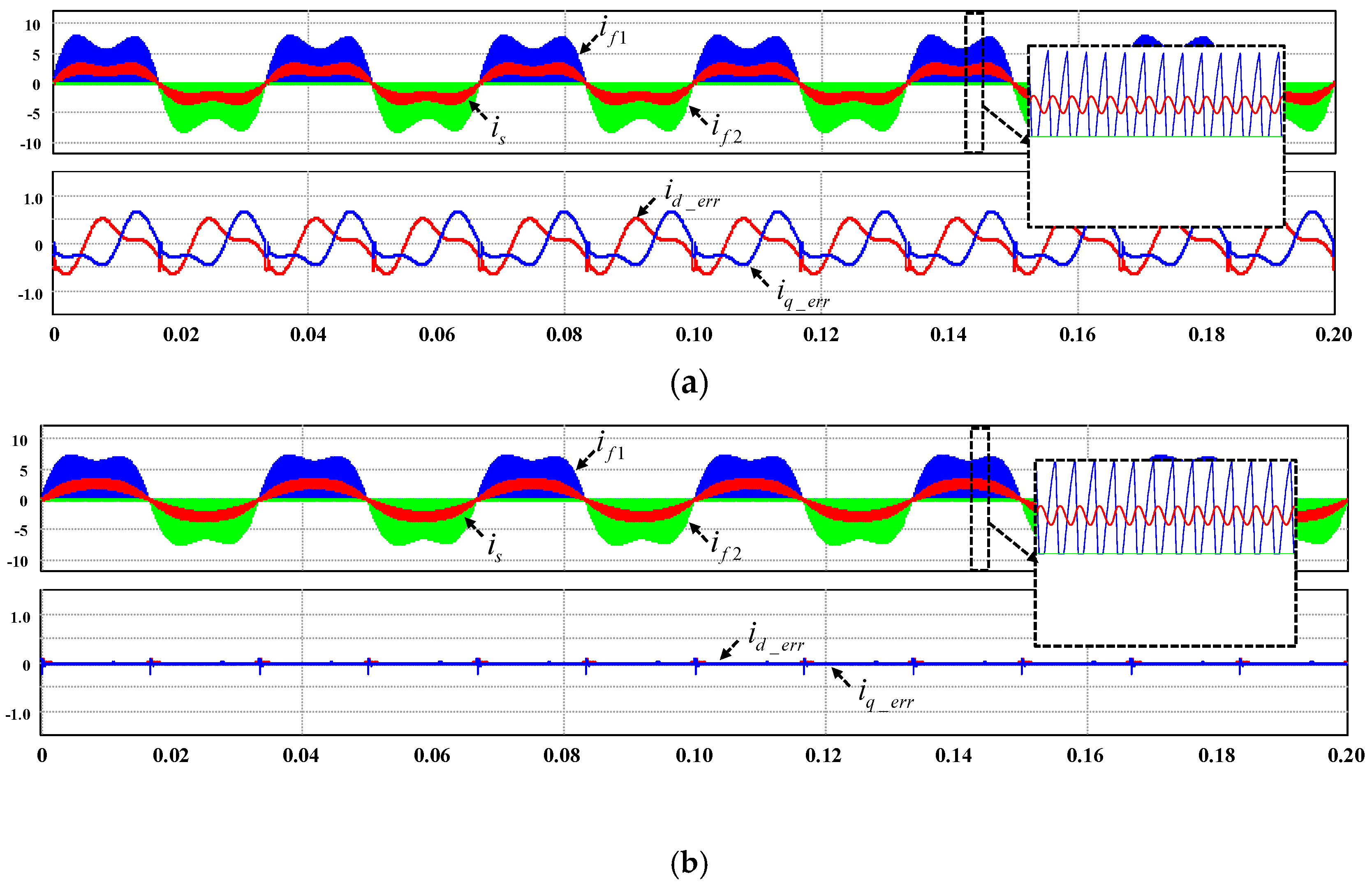
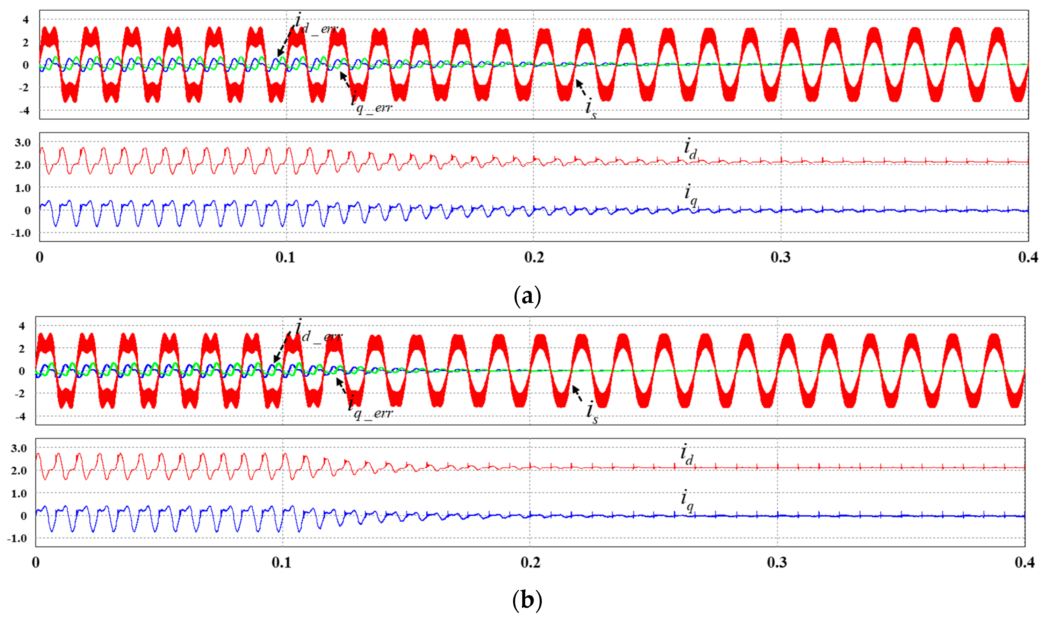
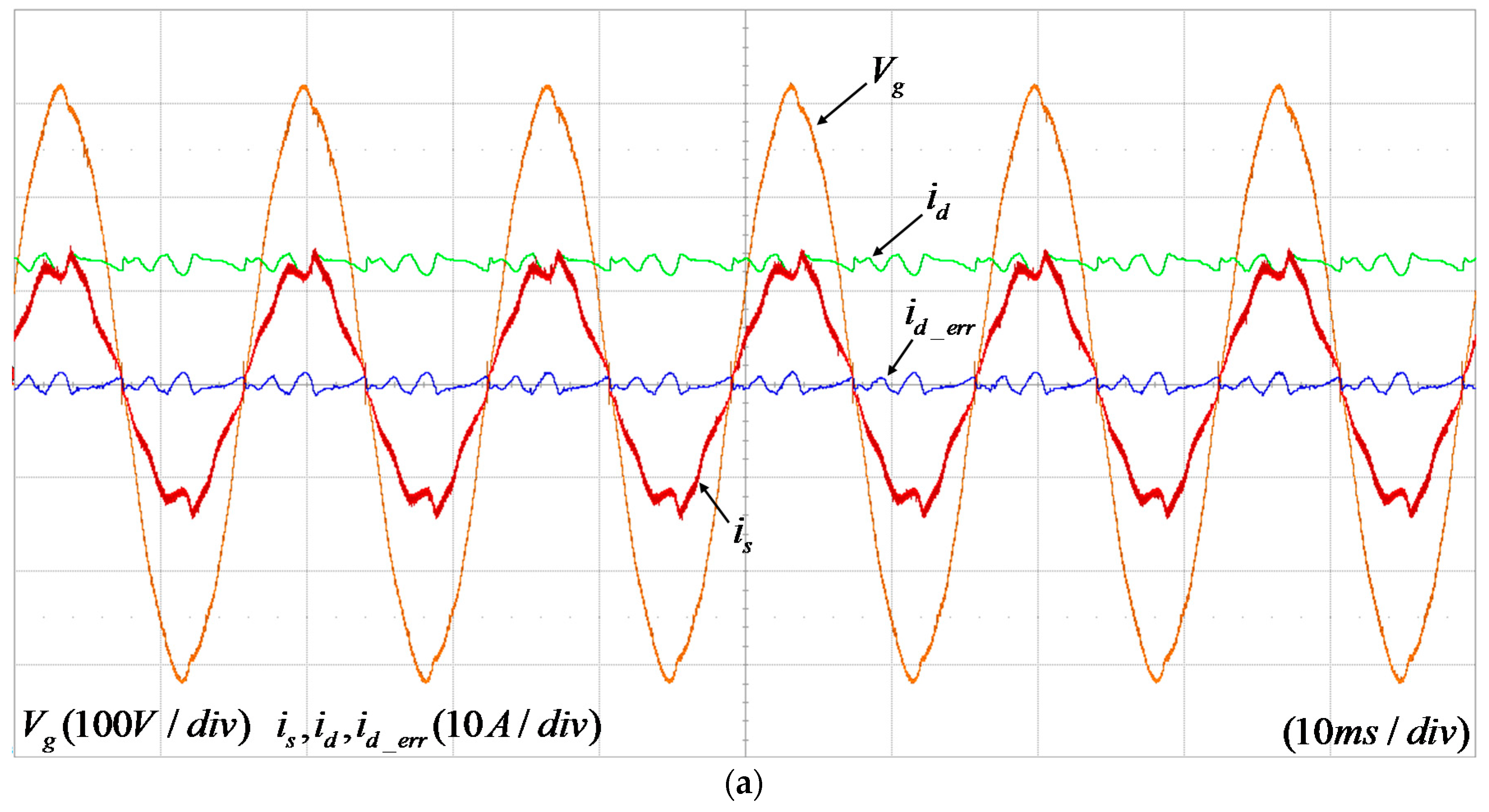
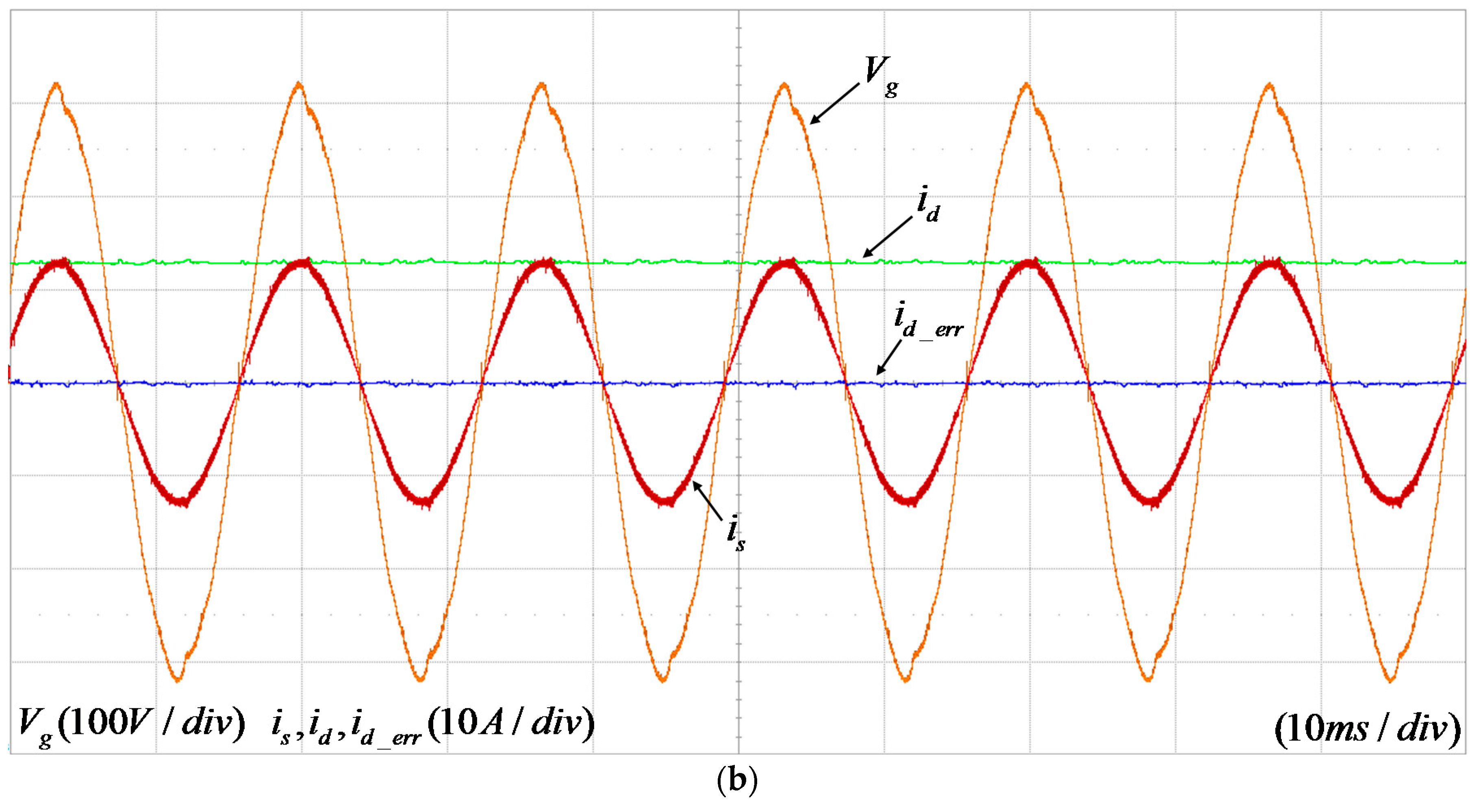
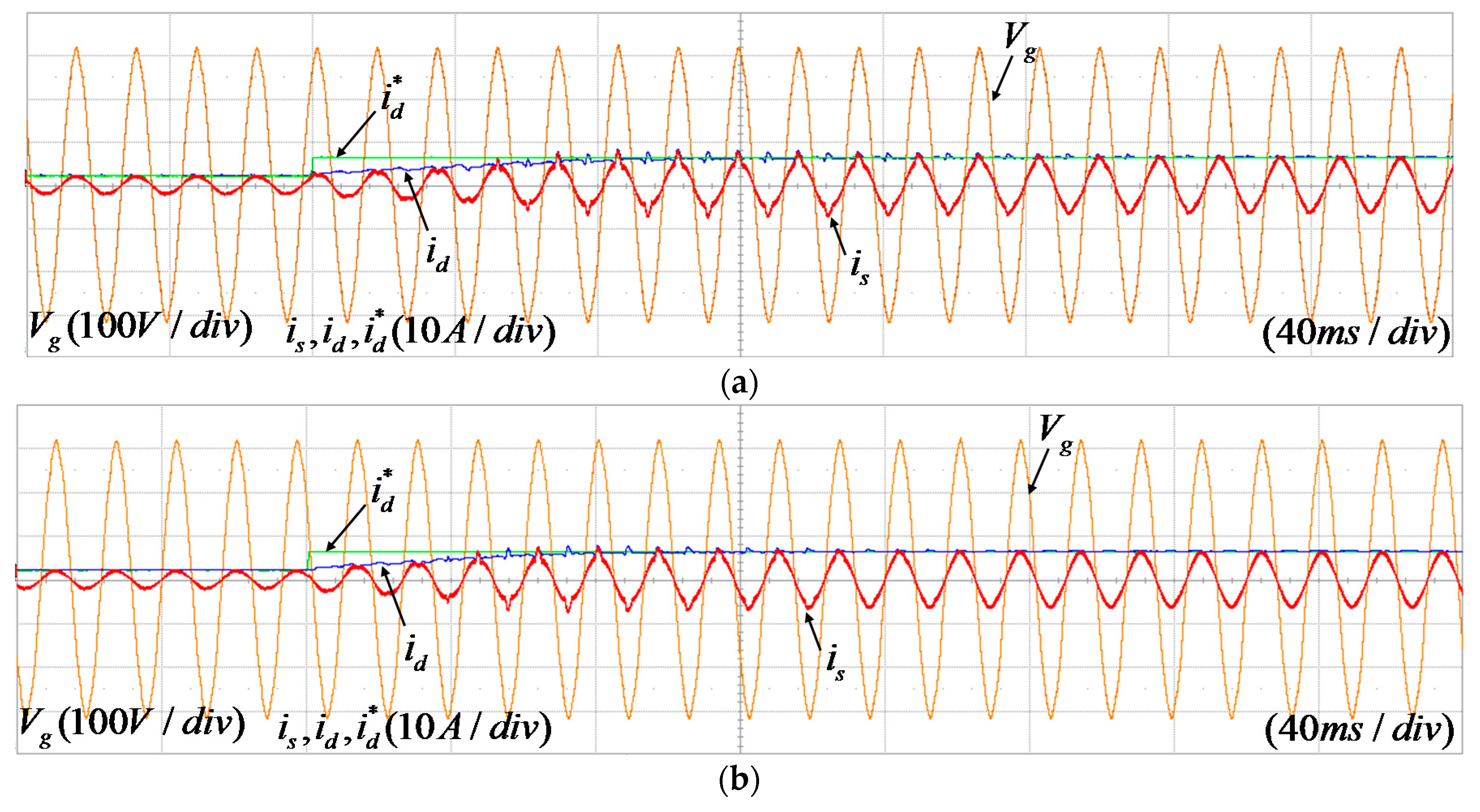
4. Simulation and Experimental Result

4.1. Simulation Results

Figure 12 shows the simulation results of the current control under a light load condition, 300 W. For simulations, the power electronics simulation package PSIM from Power SIM was utilized. The parameters used in the simulation are summarized in Table 1. As can be seen in the figure, i f 1 and i f 2 are operated in DCM. Apparently, using only the PI controllers cannot compensate the current distortion as shown in Figure 12a. The periodic error caused by the DCM operation not only worsens the THD, but also deteriorates the power tracking accuracy. The second-order harmonic component is dominantly detected in the SRF. However, once the proposed repetitive controller is applied, the current error in the SRF is almost perfectly cancelled out, as can be seen in Figure 12b.
Figure 13 compares the transient responses of two repetitive control schemes, the traditional repetitive controller that compensates all harmonics, and the even harmonic repetitive controller. In Figure 13a, the original repetitive controller starts at t = 0.1 s. About 0.2 s later, the current errors in both the SRF become within 0.1 A, except small pulses near the zero crossing points of the grid current. On the other hand, it takes less than 0.1 s for same amount of error convergence with the even harmonic repetitive control strategy. As the number of samples to iterate the error signal in the even harmonic repetitive controller is half the original one, it is reasonable that the convergence time of the error is shorter. Thus, the proposed control scheme has better transient characteristics.

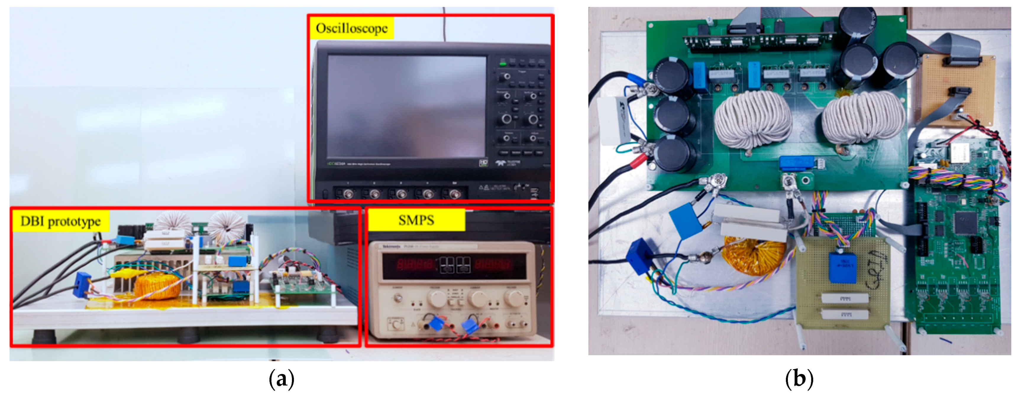
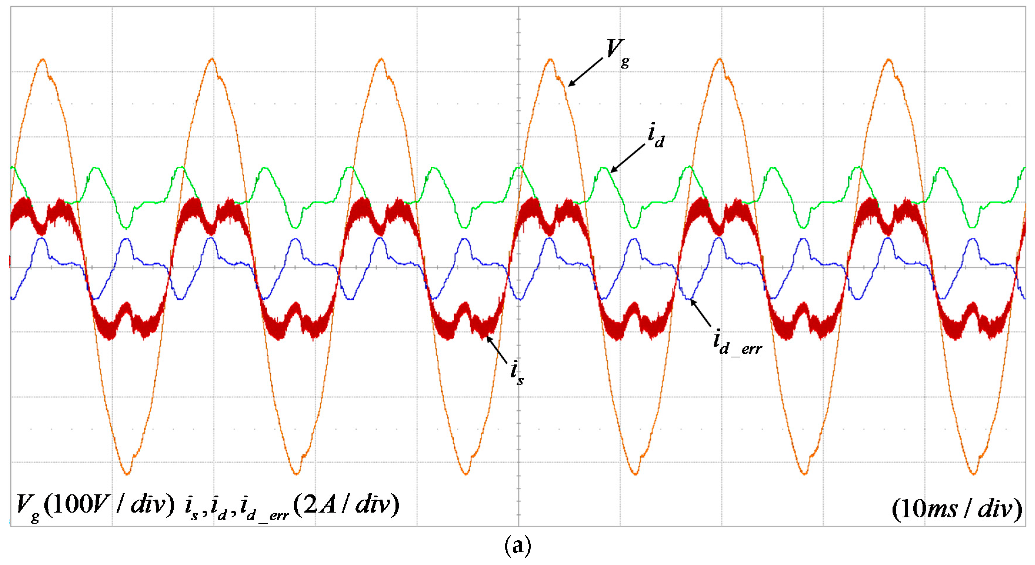
4.2. Experimental Results

Experiments were conducted to verify the effectiveness of the designed control strategy. The same parameters expressed in Table 1 were employed. Figure 14 illustrates the experimental setup of the DBI. For the DBI’s switching devices, silicon carbide (SiC) MOSFET C3M0065090D manufactured from Cree (Durham, NC, USA) were employed. Although the conduction loss seems higher than other optimized devices, the body diode of C3M0065090D was utilized for freewheeling diodes for testing purpose. For controller implementation, a TMS320F28335 digital signal processor (DSP) manufactured from Texas Instruments (Dallas, TX, USA) was used. The in-house designed DSP board has the additional circuits for digital-to-analog converter (DAC) to monitor the internal variables in the DSP. The dc-link and the grid voltage and the grid current are measured by using LEM’s (Geneva, Switzerland) LA55-P and LV25-P.
The proposed controller in Section 3 was implemented. The repetitive control gain Krp is chosen as 0.003. In fact, this value is different with the analysis taken in the previous section. It is supposed that the sensing noise, the non-ideal switching characteristics of the switching devices, and the digital propagation delay cause the selection of a lower gain compared with the simulation results.
Figure 15a shows the experimental result of the current control using the PI controller under 300 W operating condition. Here, id and id_err are monitored with the DAC in the DSP board. As shown in the figure, the third harmonic component in the output current becomes dominant as a result of the DCM operation with the traditional PI control strategy. The THD of the output current is calculated as 35.75% in this case.
On the contrary, with the proposed repetitive control scheme, no harmonic components are existent in the current errors. Only the error spikes near the zero crossing points of the grid current and the magnitude jumps in the grid voltage are monitored. Apparently, a more sinusoidal shape of the current is achieved, and the THD is measured as 10.59%.
Figure 16 compares the experimental results with and without the proposed repetitive control scheme at 2 kW condition. If no repetitive controller is applied, somewhat low frequency harmonics are present in the current error. The THD of the output current is 8.2% at this condition. According to the IEEE-929 standard, this obviously violates the THD standard for PV inverters less than 10 kW [36]. However, if the proposed repetitive controller is applied in Figure 16b, the current error is close to zero, and the output current is very well regulated with almost a sinusoidal shape even under the distorted grid voltage condition. At this mode, the THD is improved to 3.7%, and this satisfies the IEEE-929 standard.
Figure 17 shows the results of the dynamic response of the conventional repetitive controller and the even harmonic repetitive controller. The transient response is tested when the current reference is changed from 300 W to 1 kW. As shown in figure, the dynamic response of the current control using the even harmonic repetitive controller is better.

5. Conclusions

This paper presents the even harmonic repetitive control strategy in the SRF for the dual-buck PV inverter application. The system transfer functions in the SRF were derived by using the concept of the real and the imaginary orthogonal circuits. By using the transfer functions, the loop-gain of the proposed control strategy is analyzed. Although the even harmonic repetitive controller is designed in the SRF, the odd harmonic components are eliminated in the grid current. As the number of iterative samples in the proposed method is half the original repetitive control scheme, the error convergence time is significantly reduced, and the accuracy of the reference tracking performance is improved. Both the simulation and the experimental results on 2 kW DBI show that the proposed repetitive controller not only advances the dynamic properties of the current control, but also improves the THD of the output current. At 15% load condition, where the DBI operates in the DCM, the THD of the output current was improved from 35.75% to 10.59% using the proposed method. For the full load condition, the THD was measured as 8.2% with the traditional PI controller, but it dropped to 3.7% with the proposed method. Finally, the current reference was changed from 0.3 kW to 1 kW to compare the dynamic response of the even harmonic repetitive controller with the conventional one. The experimental results show that the even harmonic repetitive controller has better performance.

Author Contributions

J.-Y.L. implemented the system and performed the experiments. Y.C. assisted with the idea development and paper writing.

Funding

This work was supported by “Human Resources Program in Energy Technology” of the Korea Institute of Energy Technology Evaluation and Planning (KETEP), granted financial resource from the Ministry of Trade, Industry, and Energy, Republic of Korea. (No. 20174030201660). This research was supported by the Human Resources Program in Energy Technology of the Korea Institute of Energy Technology Evaluation and Planning (KETEP), granted financial resource from the Ministry of Trade, Industry, and Energy, Republic of Korea (No. 20174010201540).

Conflicts of Interest

The author declare no conflict of interest.

References

  1. Ayompe, L.; Duffy, A.; McCormack, S.; Conlon, M. Measured performance of a 1.72 kW rooftop grid connected photovoltaic system in Ireland. Energy Convers. Manag. 2011, 52, 816–825. [Google Scholar] [CrossRef]
  2. Díez-Mediavilla, M.; Dieste-Velasco, M.; Rodríguez-Amigo, M.d.C.; García-Calderón, T.; Alonso-Tristán, C. Performance of grid-tied PV facilities based on real data in Spain: Central inverter versus string system. Energy Convers. Manag. 2014, 86, 1128–1133. [Google Scholar] [CrossRef] [Green Version]
  3. Blaabjerg, F.; Chen, Z.; Kjaer, S.B. Power electronics as efficient interface in dispersed power generation systems. IEEE Trans. Power Electron. 2004, 19, 1184–1194. [Google Scholar] [CrossRef]
  4. IEA-PVPS. Trends in Photovoltaic Applications; Survey Report of Selected IEA Countries between 1992 and 2016; IEA: Paris, France, 2014. [Google Scholar]
  5. Freddy, T.K.S.; Rahim, N.A.; Hew, W.-P.; Che, H.S. Comparison and analysis of single-phase transformerless grid-connected PV inverters. IEEE Trans. Power Electron. 2014, 29, 5358–5369. [Google Scholar] [CrossRef]
  6. Chen, B.; Sun, P.; Liu, C.; Chen, C.-L.; Lai, J.-S.; Yu, W. High efficiency transformerless photovoltaic inverter with wide-range power factor capability. In Proceedings of the 2012 Twenty-Seventh Annual IEEE on Applied Power Electronics Conference and Exposition (APEC), Orlando, FL, USA, 5–9 February 2012; pp. 575–582. [Google Scholar]
  7. Kerekes, T.; Teodorescu, R.; Rodríguez, P.; Vázquez, G.; Aldabas, E. A new high-efficiency single-phase transformerless PV inverter topology. IEEE Trans. Ind. Electron. 2011, 58, 184–191. [Google Scholar] [CrossRef] [Green Version]
  8. Kafle, Y.R.; Town, G.E.; Guochun, X.; Gautam, S. Performance comparison of single-phase transformerless PV inverter systems. In Proceedings of the 2017 IEEE Applied Power Electronics Conference and Exposition (APEC), Tampa, FL, USA, 26–30 March 2017; pp. 3589–3593. [Google Scholar]
  9. Teodorescu, R.; Liserre, M.; Rodriguez, P. Grid Converters for Photovoltaic and Wind Power Systems; John Wiley & Sons: Hoboken, NJ, USA, 2011; Volume 29. [Google Scholar]
  10. Chen, B.; Lai, J.-S. A family of single-phase transformerless inverters with asymmetric phase-legs. In Proceedings of the 2015 IEEE Applied Power Electronics Conference and Exposition (APEC), Charlotte, NC, USA, 15–19 March 2015; pp. 2200–2205. [Google Scholar]
  11. Yu, W.; Lai, J.-S.J.; Qian, H.; Hutchens, C. High-efficiency MOSFET inverter with H6-type configuration for photovoltaic nonisolated AC-module applications. IEEE Trans. Power Electron. 2011, 26, 1253–1260. [Google Scholar] [CrossRef]
  12. Huang, Q.; Ma, Q.; Huang, A.Q. Single-phase dual-mode four-switch Buck-Boost Transformerless PV inverter with inherent leakage current elimination. In Proceedings of the 2018 IEEE Applied Power Electronics Conference and Exposition (APEC), San Antonio, TX, USA, 4–8 March 2018; pp. 3211–3217. [Google Scholar]
  13. Xiao, H.; Xie, S.; Chen, Y.; Huang, R. An optimized transformerless photovoltaic grid-connected inverter. IEEE Trans. Ind. Electron. 2011, 58, 1887–1895. [Google Scholar] [CrossRef]
  14. Zhang, L.; Sun, K.; Feng, L.; Wu, H.; Xing, Y. A family of neutral point clamped full-bridge topologies for transformerless photovoltaic grid-tied inverters. IEEE Trans. Power Electron. 2013, 28, 730–739. [Google Scholar] [CrossRef]
  15. Ma, L.; Kerekes, T.; Teodorescu, R.; Jin, X.; Floricau, D.; Liserre, M. The high efficiency transformer-less PV inverter topologies derived from NPC topology. In Proceedings of the 13th European Conference on Power Electronics and Applications, EPE’09, Barcelona, Spain, 8–10 September 2009; pp. 1–10. [Google Scholar]
  16. Cho, Y. Dual-buck residential photovoltaic inverter with a high-accuracy repetitive current controller. Renew. Energy 2017, 101, 168–181. [Google Scholar] [CrossRef]
  17. Hwang, D.-H.; Lee, J.-Y.; Cho, Y. Single-phase single-stage dual-buck photovoltaic inverter with active power decoupling strategy. Renew. Energy 2018, 126, 454–464. [Google Scholar] [CrossRef]
  18. Hong, F.; Liu, J.; Ji, B.; Zhou, Y.; Wang, J.; Wang, C. Interleaved dual buck full-bridge three-level inverter. IEEE Trans. Power Electron. 2016, 31, 964–974. [Google Scholar] [CrossRef]
  19. Monfared, M.; Golestan, S.; Guerrero, J.M. Analysis, design, and experimental verification of a synchronous reference frame voltage control for single-phase inverters. IEEE Trans. Ind. Electron. 2014, 61, 258–269. [Google Scholar] [CrossRef]
  20. Han, Y.; Fang, X.; Yang, P.; Wang, C.; Xu, L.; Guerrero, J.M. Stability Analysis of Digital-Controlled Single-Phase Inverter With Synchronous Reference Frame Voltage Control. IEEE Trans. Power Electron. 2018, 33, 6333–6350. [Google Scholar] [CrossRef] [Green Version]
  21. Zhang, R.; Cardinal, M.; Szczesny, P.; Dame, M. A grid simulator with control of single-phase power converters in DQ rotating frame. In Proceedings of the 2002 IEEE 33rd Annual Power Electronics Specialists Conference, PESC 02, Cairns, QLD, Australia, 23–27 June 2002; pp. 1431–1436. [Google Scholar]
  22. Hiti, S.; Boroyevich, D. Control of front-end three-phase boost rectifier. In Proceedings of the Ninth Annual Applied Power Electronics Conference and Exposition, APEC’94, Orlando, FL, USA, 13–17 February 1994; pp. 927–933. [Google Scholar]
  23. Hiti, S.; Borojevic, D.; Ambatipudi, R.; Zhang, R.; Jiang, Y. Average current control of three-phase PWM boost rectifier. In Proceedings of the 26th Annual IEEE Power Electronics Specialists Conference, PESC’95 Record, Atlanta, GA, USA, 18–22 June 1995; pp. 131–137. [Google Scholar]
  24. Roshan, A.; Burgos, R.; Baisden, A.C.; Wang, F.; Boroyevich, D. A DQ frame controller for a full-bridge single phase inverter used in small distributed power generation systems. In Proceedings of the APEC 2007-Twenty Second Annual IEEE Applied Power Electronics Conference, Anaheim, CA, USA, 25 February–1 March 2007; pp. 641–647. [Google Scholar]
  25. Kim, R.-Y.; Choi, S.-Y.; Suh, I.-Y. Instantaneous control of average power for grid tie inverter using single phase DQ rotating frame with all pass filter. In Proceedings of the 30th Annual Conference of IEEE Industrial Electronics Society, IECON 2004, Busan, Korea, 2–6 November 2004; pp. 274–279. [Google Scholar]
  26. Griñó, R.; Costa-Castelló, R.; Fossas, E. Digital control of a single-phase shunt active filter. In Proceedings of the 2003 IEEE 34th Annual Power Electronics Specialist Conference, PESC’03, Acapulco, Mexico, 15–19 June 2003; pp. 1038–1042. [Google Scholar]
  27. Liu, T.; Wang, D.; Zhou, K. High-performance grid simulator using parallel structure fractional repetitive control. IEEE Trans. Power Electron. 2016, 31, 2669–2679. [Google Scholar] [CrossRef]
  28. Pandove, G.; Trivedi, A.; Singh, M. Repetitive control-based single-phase bidirectional rectifier with enhanced performance. IET Power Electron. 2016, 9, 1029–1036. [Google Scholar] [CrossRef]
  29. Cho, Y.; Lai, J.-S. Digital plug-in repetitive controller for single-phase bridgeless PFC converters. IEEE Trans. Power Electron. 2013, 28, 165–175. [Google Scholar]
  30. Costa-Castelló, R.; Grinó, R.; Fossas, E. Odd-harmonic digital repetitive control of a single-phase current active filter. IEEE Trans. Power Electron. 2004, 19, 1060–1068. [Google Scholar] [CrossRef]
  31. Yang, S.; Wang, P.; Tang, Y.; Zagrodnik, M.; Hu, X.; Tseng, K.J. Circulating current suppression in modular multilevel converters with even-harmonic repetitive control. IEEE Trans. Ind. Appl. 2018, 54, 298–309. [Google Scholar] [CrossRef]
  32. Zhou, K.; Wang, D.; Zhang, B.; Wang, Y. Plug-in dual-mode-structure repetitive controller for CVCF PWM inverters. IEEE Trans. Ind. Electron. 2009, 56, 784–791. [Google Scholar] [CrossRef]
  33. Zhou, K.; Wang, D. Digital repetitive controlled three-phase PWM rectifier. IEEE Trans. Power Electron. 2003, 18, 309–316. [Google Scholar] [CrossRef] [Green Version]
  34. Chew, K.K.; Tomizuka, M. Digital control of repetitive errors in disk drive systems. In Proceedings of the American Control Conference, Milwaukee, WA, USA, 27–29 June 1989; pp. 540–548. [Google Scholar]
  35. Zou, Z.-X.; Zhou, K.; Wang, Z.; Cheng, M. Frequency-adaptive fractional-order repetitive control of shunt active power filters. IEEE Trans. Ind. Electron. 2015, 62, 1659–1668. [Google Scholar] [CrossRef]
  36. The Institute of Electrical and Electronics Engineers, Inc. IEEE Recommened Practice for Utility Interface of Photovoltaic(PV) System; IEEE Std. 929-2000: April 2000; The Institute of Electrical and Electronics Engineers, Inc.: New York, NY, USA, 2000. [Google Scholar]
Figure 1. The circuit structure of the three-level dual-buck photovoltaic (PV) inverter.
Electronics 07 00226 g001
Figure 2. The duty reference d and the switching signals for the switching devices.
Electronics 07 00226 g002
Figure 3. Real circuit and imaginary orthogonal circuit.
Electronics 07 00226 g003
Figure 4. Average circuit model of the real circuit and the imaginary orthogonal circuit.
Electronics 07 00226 g004
Figure 5. Single phase dual buck inverter DQ controller. APF—all pass filter; PLL—phase locked loop.
Electronics 07 00226 g005
Figure 6. Current control strategy for the dual-buck inverter. PI—proportional integral.
Electronics 07 00226 g006
Figure 7. Loop-gain bode plot.
Electronics 07 00226 g007
Figure 8. Repetitive control block scheme.
Electronics 07 00226 g008
Figure 9. The proposed even harmonic repetitive current control strategy for dual-buck inverters.
Electronics 07 00226 g009
Figure 10. The root loci of H ( z ) with different Krp.
Electronics 07 00226 g010
Figure 11. Current control loop-gain of Gie(z).
Electronics 07 00226 g011
Figure 12. Current response under 300 W operation (a) with the PI controller and (b) with the proposed controller.
Electronics 07 00226 g012
Figure 13. Current response under 300 W operation (a) with the original repetitive controller and (b) with the even harmonics repetitive controller.
Electronics 07 00226 g013
Figure 14. The experimental setup; (a) experimental setup and (b) 2 kW dual-buck inverters (DBI) prototype.
Electronics 07 00226 g014
Figure 15. Experimental result under 300 W condition (a) with PI controller and (b) with proposed controller.
Electronics 07 00226 g015aElectronics 07 00226 g015b
Figure 16. Experimental result under 2 kW condition (a) with PI controller and (b) with proposed controller.
Electronics 07 00226 g016aElectronics 07 00226 g016b
Figure 17. Experimental result of dynamic response (a) using conventional repetitive controller and (b) using even harmonic repetitive controller.
Electronics 07 00226 g017
Table 1. System parameters.
ParameterValue (unit)
Switching frequency ( f s w )18 kHz
Inverter side inductor ( L f )0.5 mH
Grid side inductor ( L s )0.5 mH
Filter capacitor ( C f )1 μ F
Damping Resistor ( R d )5 Ω
Grid voltage in RMS220 V/60 Hz
DC link voltage ( V d c )380 V

