Article

Embedded Real-Time Implementation of a Two-Diode Model Photovoltaic Emulator Using dSPACE for Hardware Validation

by
Flavius-Maxim Petcut
1,*,
Anca-Adriana Petcut-Lasc
2,3,* and
Valentina Emilia Balas
1,4
1
Faculty of Engineering, “Aurel Vlaicu” University of Arad, 310032 Arad, Romania
2
Doctoral School of Systems Engineering, Petroleum-Gas University of Ploiesti, 100680 Ploiesti, Romania
3
Faculty of Exact Sciences, “Aurel Vlaicu” University of Arad, 310032 Arad, Romania
4
Academy of Romanian Scientists, 050044 Bucharest, Romania
*
Authors to whom correspondence should be addressed.
Electronics 2026, 15(8), 1765; https://doi.org/10.3390/electronics15081765
Submission received: 29 March 2026 / Revised: 10 April 2026 / Accepted: 13 April 2026 / Published: 21 April 2026
(This article belongs to the Special Issue Embedded Systems and Microcontroller Smart Applications)

Abstract

This paper presents the design, implementation, and experimental validation of a real-time embedded photovoltaic (PV) emulator based on the two-diode model, using a dSPACE DS1103 platform for hardware validation. The proposed system aims to accurately reproduce the electrical behavior of PV modules under varying environmental conditions, including irradiance and temperature variations. The emulator architecture combines a lookup-table-based modelling approach with a programmable DC power source, enabling deterministic real-time execution and efficient implementation. A multi-level control structure is employed, integrating inner-loop regulation, model-based reference generation, and feedback control to ensure accurate tracking of the PV current–voltage (I–V) characteristics. Experimental results demonstrate that the emulator achieves high accuracy, with an approximation error of approximately 1.2% under standard operating conditions. The system exhibits stable dynamic behavior characterized by a time constant of approximately 0.5 s, with performance maintained across different sampling intervals and load conditions. Additional simulations confirm that the two-diode model preserves high accuracy over a temperature range of 15–60 °C, with deviations below 2%. The results highlight that the two-diode model provides an optimal trade-off between modelling accuracy and computational complexity for real-time embedded applications. The proposed emulator offers a flexible and reliable platform for laboratory validation of photovoltaic behavior and provides the foundation for future testing of maximum power point tracking (MPPT) algorithms, power electronic converters, and embedded control strategies under controlled conditions.

1. Introduction

The rapid expansion of photovoltaic (PV) systems worldwide has significantly increased the demand for reliable validation platforms for power converters and maximum power point tracking (MPPT) algorithms. According to recent reports, global PV deployment continues to grow at an accelerated rate, driven by the need for efficient and flexible renewable energy solutions [1]. However, conventional testing using real PV panels is often affected by uncontrollable environmental conditions, such as irradiance variability, temperature fluctuations, and partial shading, which reduce repeatability and complicate systematic evaluation [2,3,4,5,6]. Consequently, photovoltaic emulators have emerged as a practical alternative, enabling controlled and repeatable testing environments independent of environmental factors [7,8,9].
Various approaches have been proposed for the development of PV emulators, ranging from analytical models to hardware-based and hybrid implementations. Classical modelling techniques include the single-diode, two-diode, and three-diode models, which aim to reproduce the nonlinear current–voltage characteristics of PV modules with different levels of accuracy and complexity [10,11,12]. In addition, lookup table (LUT)-based approaches and artificial intelligence techniques have been investigated to improve execution speed and adaptability [13,14]. Despite these advances, the implementation of high-fidelity PV models in embedded real-time systems remains challenging due to computational constraints, limited memory resources, and strict timing requirements [15].
Embedded real-time platforms are increasingly employed for the validation of power electronics and control algorithms, particularly in applications requiring deterministic execution and low latency. In such systems, factors such as sampling frequency, communication delays, and actuator dynamics have a direct impact on system performance. The use of programmable DC power supplies in PV emulators introduces additional constraints related to command update rates and transient response, which must be carefully addressed to ensure stability and accuracy [16,17]. Furthermore, recent studies highlight the growing importance of real-time and hardware-in-the-loop (HIL) platforms for testing embedded control strategies in renewable energy systems [9,18].
Among the available modelling approaches, the two-diode model represents a suitable compromise between accuracy and computational complexity, making it well suited for real-time embedded implementation. When combined with LUT-based execution, this model enables fast computation and predictable timing behavior, which are essential for embedded systems. Moreover, parameter extraction techniques such as genetic algorithms allow accurate identification of model parameters, improving emulator fidelity without significantly increasing computational burden [19].
The cost of commercial real-time photovoltaic panel emulators is typically very high. Dedicated solar array simulators, such as those offered by Chroma (62000H-S series), Keysight (PV8900 series) produce by Chroma ATE Inc., Taoyuan City, Taiwan, or AMETEK (Elgar TerraSAS) produce by AMETEK Programmable Power, Inc., San Diego, CA, USA, are designed for high-bandwidth MPPT testing and can cost from several thousand to tens of thousands of USD per unit depending on voltage and power ratings [20,21]. Similarly, complete HIL platforms based on dSPACE SCALEXIO for power electronics applications are priced at approximately 31,500 USD in discounted academic configurations, while industry pricing exceeds 74,000 USD [22]. In contrast, this paper presents an emulator implementation realized entirely using equipment commonly available in university research laboratories, specifically, a dSPACE DS1103 controller (dSPACE GmbH, Paderborn, Germany) [23] and a general-purpose programmable DC power source (EXTECH 382280, priced at approximately 650 USD, Extech, New Taipei City, Taiwan [24]). The proposed approach does not require the acquisition of specialized PV emulation hardware. Unlike most existing studies that focus primarily on model accuracy or converter design, this work provides a detailed experimental characterization of the programmable source dynamics, including the identification of its time constant and random dead time, which are rarely reported in the literature. This characterization enables informed selection of update rates and control parameters, contributing a practical methodology for researchers seeking to develop cost-effective PV emulators from general-purpose laboratory instruments.
This paper proposes an embedded real-time implementation of a photovoltaic emulator based on the two-diode model, using a dSPACE DS1103 platform for hardware validation of power converters and MPPT algorithms. The proposed architecture integrates an LUT-based PV model with a serially controlled programmable DC source, enabling flexible and accurate emulation under varying operating conditions. A detailed analysis of the embedded implementation is provided, including the impact of communication delays, discretization effects, and source dynamics on system performance.
The main contributions of this work are as follows:
Development of a real-time embedded photovoltaic emulator based on the two-diode model using a dSPACE platform;
Implementation of an LUT-based approach to ensure fast and deterministic execution suitable for real-time applications;
Experimental characterization of the programmable DC source dynamics and communication constraints;
Identification of optimal update rates considering serial interface limitations and system stability;
Validation of the emulator under different load conditions and discretization steps, demonstrating accurate and stable operation for hardware testing of MPPT and power converters.
The remainder of this paper is organized as follows. Section 2 reviews existing PV emulator implementations and real-time approaches. Section 3 presents the proposed embedded architecture and modelling methodology. Section 4 describes the experimental setup and system characterization. Section 5 discusses the experimental results. Finally, Section 6 concludes the paper.

2. Related Work on PV Emulators and Real-Time Implementations

This section reviews the main approaches reported in the literature for photovoltaic emulator development, with a particular focus on architectures, modelling techniques, and real-time embedded implementations. The analysis is structured into three main parts. First, the principal PV emulator topologies are discussed, highlighting their advantages and limitations. Next, commonly used PV modelling approaches are examined in terms of accuracy and computational complexity. Finally, real-time and embedded implementations are analyzed, with emphasis on hardware constraints, communication delays, and system performance. Based on this review, the main research gaps are identified, motivating the approach proposed in this work.

2.1. PV Emulator Topologies and Architectures

PV emulators reported in the literature can be broadly classified into three main categories: (i) software-based emulators, (ii) hardware-based emulators using programmable power supplies or power converters, and (iii) hybrid solutions combining real-time digital simulators with physical hardware interfaces.
Software-based emulators, typically implemented in environments such as MATLAB/Simulink 7.6.0 or LabVIEW 2022 Q3, provide high flexibility and ease of implementation. They enable rapid prototyping and efficient testing of control algorithms under various simulated operating conditions. However, their main limitation is the inability to deliver real electrical power to physical loads, restricting their applicability to offline analysis and algorithm development [25,26,27,28].
Hardware-based emulators, which rely on programmable DC power supplies or DC–DC converters, are capable of reproducing the electrical behavior of PV modules in real time. These systems can supply actual current and voltage to external loads, making them suitable for experimental validation of MPPT algorithms and power electronic converters. Nevertheless, their performance is often constrained by bandwidth limitations, response time, and the cost of high-performance power sources [29,30,31,32].
A comparative summary of representative PV emulator implementations is provided in Table 1.
Hybrid approaches, also known as hardware-in-the-loop (HIL) systems, combine real-time digital simulation platforms, such as dSPACE or OPAL-RT, with physical hardware components. These systems provide high fidelity and enable comprehensive testing of embedded control strategies. However, they typically involve increased system complexity, higher implementation costs, and the need for specialized expertise [19,23,33,34].
Despite the wide range of existing solutions, achieving accurate real-time emulation under hardware and communication constraints remains a significant challenge.

2.2. PV Modeling Approaches for Emulation

The performance of a PV emulator strongly depends on the selected modelling approach. The most widely used analytical models include the single-diode model (SDM), the two-diode model (TDM), and the three-diode model (ThDM), each offering different trade-offs between accuracy and computational complexity.
The SDM is commonly adopted due to its simplicity and reduced computational requirements, making it suitable for embedded implementations. However, its accuracy is limited, especially under varying environmental conditions. The TDM improves modelling accuracy by incorporating recombination losses, while maintaining a reasonable computational burden, making it suitable for real-time applications [11,12]. The ThDM further enhances accuracy but significantly increases computational complexity, limiting its applicability in embedded systems.
To address real-time constraints, lookup table (LUT)-based methods have been proposed, enabling fast evaluation of PV characteristics with reduced computational overhead. Advanced approaches based on optimization algorithms, such as genetic algorithms, have also been employed to improve parameter identification accuracy and model fidelity [35,36]. While these methods enhance accuracy, their implementation must be carefully optimized to meet real-time execution requirements.

2.3. Real-Time and Embedded Implementations

The implementation of PV emulators on embedded real-time platforms introduces additional challenges related to hardware limitations and timing constraints. Various platforms have been explored in the literature, including microcontrollers, digital signal processors (DSPs), field-programmable gate arrays (FPGAs), and real-time prototyping systems.
FPGA-based implementations offer high computational performance and parallel processing capabilities, enabling accurate and fast emulation of PV characteristics. However, they require complex development processes and specialized design expertise [37]. Microcontroller-based solutions are more cost-effective and easier to implement, but they are limited by processing power and memory resources, which can restrict model complexity and execution speed [17].
Real-time simulation platforms, such as dSPACE and OPAL-RT, provide flexible environments for rapid prototyping and hardware-in-the-loop (HIL) testing. These platforms enable deterministic execution and seamless integration with control systems, making them suitable for validating power electronics applications [19,24]. However, practical implementations must account for communication delays, sampling limitations, and actuator dynamics, which can significantly affect emulator performance.
Recent studies have emphasized the importance of evaluating real-time performance, including execution timing, stability, and dynamic response, when implementing PV emulators in embedded environments [9,38]. Nevertheless, many existing works focus primarily on model accuracy, while insufficient attention is given to hardware-induced constraints and communication interfaces.

2.4. Research Gaps and Motivation

Based on the reviewed literature, several limitations can be identified in existing PV emulator implementations. First, many studies prioritize model accuracy without adequately addressing real-time execution constraints and hardware limitations. Second, the dynamic behavior of programmable DC sources and their influence on system stability are often insufficiently analyzed. Third, the impact of communication delays and update rates on emulator performance is rarely investigated in detail.
Furthermore, there is a lack of comprehensive experimental validation that simultaneously considers modelling accuracy, real-time constraints, and hardware dynamics. This gap is particularly relevant for embedded systems used in MPPT and power electronics applications, where deterministic behavior and stability are essential.
To address these challenges, this work proposes a real-time embedded PV emulator based on the two-diode model, with a focus on practical implementation constraints, communication effects, and dynamic system behavior.

3. Proposed Embedded PV Emulator Architecture and Modelling Methodology

This section presents the proposed embedded PV emulator architecture, including the modelling approach, hardware design, control strategy, and real-time implementation. The objective is to accurately reproduce the electrical behavior of a PV panel under varying environmental conditions while ensuring deterministic execution and stability in a real-time embedded environment.
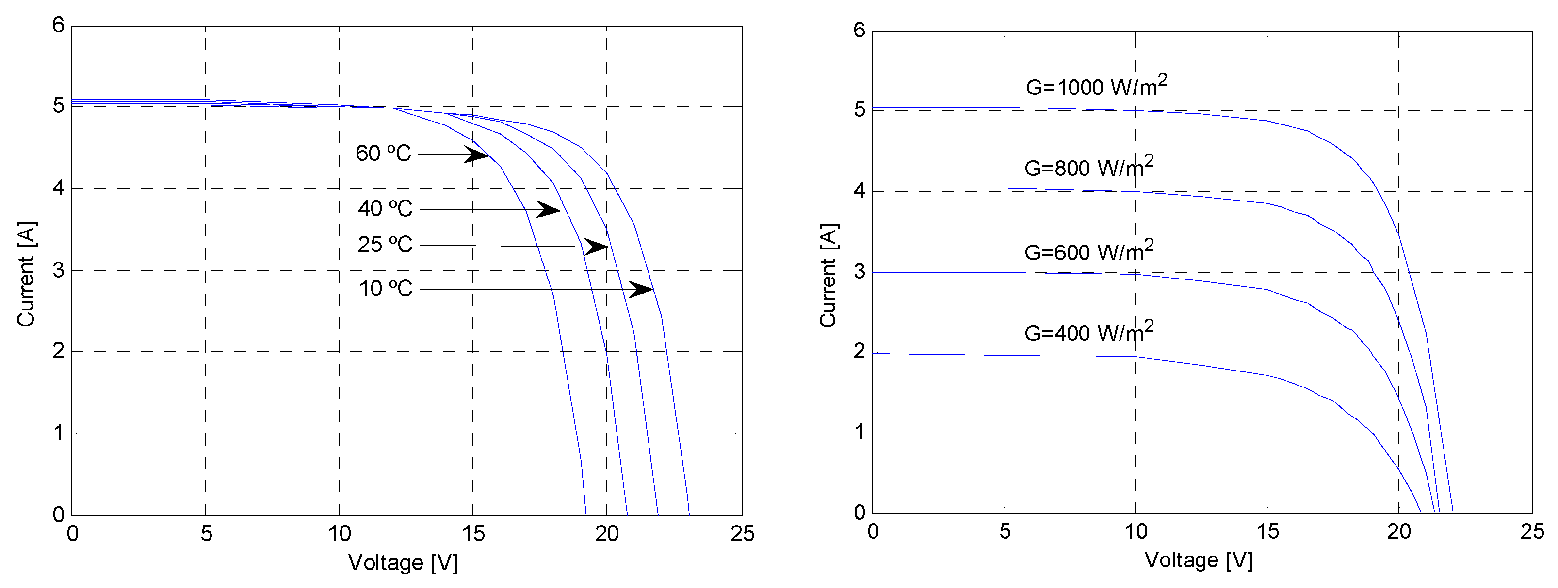
The used I-V characteristics presented in Figure 1 are from [39]. On the left are the temperatures variation and on the right are the sun radiation variation.

3.1. PV Panel Modelling

Accurate modelling of photovoltaic devices is essential for emulator development, since the output characteristics of the emulator must closely reproduce those of a real PV panel. Equivalent circuit models are widely used for this purpose because they offer a practical representation of the nonlinear current–voltage relationship of photovoltaic modules under different irradiance and temperature conditions [11,12,13,14]. Depending on the required trade-off between accuracy and computational burden, several model structures can be adopted, the most common being the single-diode, two-diode, and three-diode models [12,13,40].

3.1.1. Single-Diode Model (SDM)

The single-diode model is one of the most widely used equivalent circuit representations of a photovoltaic cell due to its relatively simple structure and satisfactory accuracy under standard operating conditions [11,13,14]. It consists of a photocurrent source, one diode describing the p–n junction behavior, a series resistance accounting for internal ohmic losses, and a shunt resistance representing leakage currents.
The output current of the model is expressed as:
I = I p h I 0 · e V + I · R s n · V t 1 V + I · R s R p
where I p h is the photocurrent, I 0 the reverse saturation current, R s and R p the series and shunt resistances (or parallel resistance), n the diode ideal factor, and V t the thermal voltage. SDM is attractive because of its reduced computational complexity, but its accuracy may degrade under low-irradiance conditions and in situations where recombination effects become more significant [12,40]. For this reason, more detailed models are often preferred when higher fidelity is required.

3.1.2. Two-Diode Model (TDM)

The two-diode model extends the single-diode representation by introducing an additional diode to separately capture diffusion and recombination phenomena within the photovoltaic cell [12,35,36,40]. This configuration allows better approximation of the I-V curve, especially in the low-voltage region and under non-ideal operating conditions where recombination dominates. The mathematical model is described by:
I = I p h I 01 · [ e V + I · R s n 1 · V t 1 ] I 02 · [ e V + I · R s n 2 · V t 1 ] V + I · R s R p
where I 01 and I 02 are the reverse saturation currents of the two diodes, and n 1 and n 2 are their corresponding ideality factors.
Compared with the SDM, the TDM provides improved modelling accuracy while still preserving a computational complexity that remains manageable for real-time implementation [12,40]. In addition, the use of optimization-based parameter extraction methods, such as genetic algorithms, further enhances the practical applicability of this model in emulator design [35,36]. Owing to this balance between accuracy and implementation effort, the two-diode model was selected as the main modelling basis for the proposed embedded PV emulator. Possible parameter identification approaches are presented in the paper [36].

3.1.3. Three-Diode Model (ThDM)

For applications requiring even higher modelling fidelity, the three-diode model can be adopted. This formulation introduces a third diode to capture additional recombination and leakage effects that may become relevant in advanced photovoltaic technologies or under strongly non-uniform operating conditions [40,41].
The corresponding mathematical expression becomes:
I = I p h I 01 · [ e V + I · R s n 1 · V t 1 ] I 02 · [ e V + I · R s n 2 · V t 1 ] I 03 · [ e V + I · R s n 3 · V t 1 ] V + I · R s R p
The three-diode model can achieve higher accuracy; at the same time, it involves a larger number of unknown parameters and a substantially increased computational burden [41]. These aspects make parameter identification more difficult and reduce its suitability for deterministic embedded real-time implementation. For this reason, despite its modelling advantages, it was not selected for the present emulator architecture.
Considering the trade-off between accuracy and computational burden, the two-diode model was selected as the primary basis for emulator implementation. Its capacity to balance modelling precision with feasible parameter extraction, particularly when combined with optimization techniques such as genetic algorithms, makes it well suited for real-time emulation.

3.2. Emulator Hardware Design

The emulator hardware was designed to reproduce the electrical behavior of photovoltaic (PV) panels in real time, enabling direct interaction with physical loads and power electronic converters. Compared to software-only approaches, hardware-based implementations provide actual voltage and current outputs, making them suitable for experimental validation of MPPT algorithms and embedded control strategies [8,9,10,29].
A programmable DC power source forms the core of the proposed system, allowing the generation of output current–voltage (I–V) characteristics defined by the selected PV model. This approach represents a practical compromise between implementation simplicity and real-time capability, as also reported in low-cost and software-driven PV emulator designs [29,31,32]. While converter-based emulators can offer faster dynamic response, programmable-source-based architectures remain attractive due to their reduced hardware complexity and ease of integration [9,18]
The main components of the emulator are:
  • Power Stage: A programmable DC source capable of operating over a wide voltage and current range, covering typical PV module operating conditions. Such solutions are widely adopted in PV emulation systems, although their dynamic response is inherently limited by internal control loops and communication delays [9,18].
  • Control and Processing Unit: A real-time embedded platform (dSPACE DS1103) is used to execute the PV model and generate control commands. Real-time platforms such as dSPACE enable rapid prototyping and deterministic execution, being widely employed in hardware-in-the-loop (HIL) testing and embedded system validation [19,24]. Alternative implementations based on FPGA or DSP platforms have also been reported, offering higher computational performance at the cost of increased development complexity [33].
  • Sensing and Feedback: Voltage and current sensors provide continuous feedback, ensuring that the emulator output matches the theoretical model and measurements are used to continuously update the emulator operating point. Accurate sensing and feedback are essential for ensuring consistency between the theoretical PV model and the physical output [16,37].
  • Communication Interface: The programmable power source is controlled via a serial communication interface (RS232), which introduces limitations in terms of command update rate and latency. These constraints must be explicitly considered in the design of the real-time control loop, as they directly affect the achievable dynamic performance of the emulator.
  • User Interface and Data Logging: A host computer allows parameter tuning, environmental condition emulation (irradiance and temperature), and recording of experimental data for validation.
In addition, the use of optimization-based parameter extraction techniques, such as genetic algorithms, combined with lookup-table (LUT) implementations, further enhances the practical applicability of hardware-based PV emulators by reducing computational burden and ensuring fast real-time execution [35,36,39].
The modular design of the proposed system ensures flexibility, allowing different PV models, control strategies, and testing conditions to be implemented without requiring hardware modifications. This adaptability is particularly important for research and development environments focused on embedded energy systems and real-time control validation.

3.3. Control Algorithms

To achieve accurate real-time emulation of photovoltaic (PV) behavior, the control system is structured in a hierarchical manner, combining fast inner-loop regulation with higher-level model-based control. This multi-layer architecture ensures both stability and accurate tracking of the desired current–voltage (I–V) characteristics under varying operating conditions. Such hierarchical control structures are widely adopted in power electronic systems and PV emulator implementations to balance dynamic performance and modelling accuracy [9,16,17,29,30]. The control framework consists of the following main components:
  • Inner Loop Control: Responsible for fast regulation of the emulator output, ensuring stability and dynamic response. Typically, current-mode or voltage-mode control strategies are employed to regulate the power stage and maintain the desired operating point. These control techniques are extensively used in power electronic converters and PV systems to improve transient response and robustness under load variations [16,38,40]. In hardware-based PV emulators, similar control structures are implemented to ensure that the generated voltage and current follow the reference characteristics with minimal error [9,18,32,34].
  • Outer Loop Modelling Control: Responsible for generating the reference voltage or current based on the photovoltaic model. The reference is computed using environmental inputs such as irradiance and temperature, allowing the emulator to reproduce realistic PV operating conditions. Model-based control approaches are commonly used in PV system simulation and emulator design, where accurate representation of environmental effects is required [2,3,4,5,17,19,23]. This separation between modelling and regulation improves modularity and enables efficient real-time implementation.
  • Parameter Identification and Adaptation: Accurate parameter identification is essential for ensuring that the emulator reproduces the behavior of real PV modules. Optimization techniques, particularly genetic algorithms, are widely used due to their robustness in solving nonlinear parameter estimation problems [25,35,36]. These methods allow the model to adapt to different PV technologies and operating conditions. Moreover, when combined with lookup-table (LUT) implementations, they significantly reduce computational complexity and enable fast real-time execution, which is critical for embedded systems [26,36].
  • Environmental Conditions Simulation: The control framework allows dynamic variation of environmental parameters, such as irradiance and temperature, enabling the emulation of realistic scenarios including partial shading and rapid environmental changes. Such conditions have a significant impact on PV system performance and are widely studied in the literature, particularly in the context of MPPT algorithm evaluation and system reliability [5,6,7,8,9,10,11,12,13,14,15,24,33,35]. The ability to reproduce these scenarios in a controlled environment is essential for validating advanced control strategies.
The synergy between accurate PV modelling, robust hardware design, and efficient control strategies results in a closed-loop system in which the operating point is continuously adjusted based on feedback measurements. This ensures convergence toward the intersection between the PV characteristic and the load line.
The combined use of accurate modelling, robust control strategies, and real-time execution enables faithful emulation of PV behavior. As a result, the proposed system provides a reliable platform for testing MPPT algorithms, power converters, and grid-integration strategies under controlled laboratory conditions [9,12,13,14,24,30].

3.4. Embedded Implementation Using dSPACE

The implementation of the proposed photovoltaic emulator is based on a real-time embedded architecture using a programmable DC power source and a dSPACE DS1103 control platform. This configuration enables hardware validation of photovoltaic behavior under controlled laboratory conditions while ensuring deterministic execution and real-time operation [24,42].
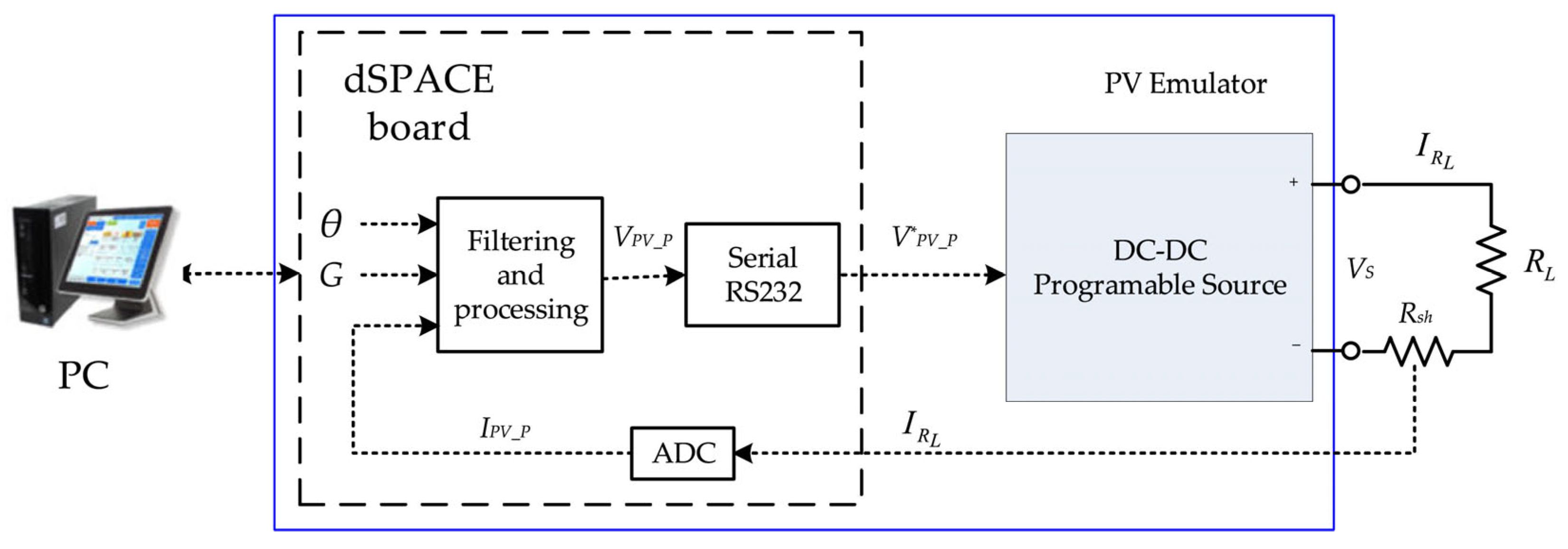
A schematic representation of the overall system architecture is shown in Figure 2. The implementation consists of a host computer, the dSPACE real-time control board, and a programmable DC source used to reproduce the output voltage of the photovoltaic module.
The dSPACE platform executes the control algorithm and the photovoltaic model in real time, generating the reference control signal V P V _ P * , which is transmitted to the programmable source via a serial communication interface. The programmable source generates the output voltage V S , which is applied to a resistive load R L . The system is designed to operate within a voltage range of up to 40 V and a current of up to 5 A, allowing the emulation of typical photovoltaic module operating conditions.
Control of the programmable source is achieved through feedback of the load current I L , I R L , obtained via a shunt resistor R s and the analogue-to-digital converter (ADC) on the dSPACE board. The measured signal is filtered and processed to ensure stable operation and accurate tracking of the reference characteristics.
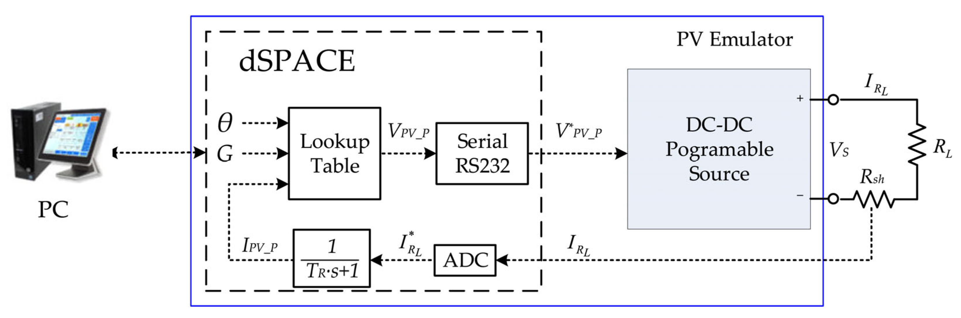
To reduce measurement noise and prevent instability, a first-order inertial element (PT1) is introduced in the feedback path. The transfer function of the filter is H F ( s ) = 1 T R s + 1 . The processing consists of generating the reference voltage based on the I–V characteristic corresponding to the current pair of values (θ, G) and the converted current signal I P V _ P . This generation is performed by means of a Lookup Table block, which stores a fixed number of PV external characteristics as reference points and, at the same time, interpolates additional points corresponding to the environmental pair (θ, G). According to these specifications, the board form in Figure 2 corresponds to the improved block diagram in Figure 3. The filtering stage ensures smoother signal transitions and mitigates high-frequency disturbances, improving the robustness of the control system [37,43]. The objective is for both the current I R L and voltage V S to match as closely as possible the current I P V _ P and voltage V P V _ P of the emulated PV panel.
The documentation of the programmable source [44] describes its programming and operating modes but does not provide detailed information regarding dynamic performance characteristics, such as response time or minimum update interval. Therefore, experimental testing was conducted to determine these parameters. It was observed that the minimum time between two successive programming commands applied through the control signal V P V _ P is approximately 0.05 s, corresponding to a maximum command sampling frequency of 20 Hz. To avoid operating near the physical limits of the source and to reduce modelling inaccuracies, a longer update period of h d S = 0.1 s was chosen, resulting in a command sampling frequency of 10 Hz.
The Lookup Table block has three inputs ( θ , G , I ) and one output V P V _ P (Vref).
Through interpolation it generates a family of I V characteristics stored by reference points.
The parameter identification procedure underlying the LUT is based on the two-diode model described in Section 3.1.2, using the genetic algorithm (GA) approach presented in [36]. In this method, the seven model parameters ( I p h , I 01 , I 02 , R s , R p , V T 1 , V T 2 ) are identified from experimentally obtained I–V data points. The GA operates on a population of 20 individuals, each representing a candidate parameter vector ( I 01 , I 02 , R s ), while R p and I p h are analytically derived from the open-circuit and short-circuit conditions, and the thermal voltages V T 1 , V T 2 are estimated from the cell temperature [36]. The fitness function minimizes the weighted root-mean-square error between measured and calculated current values across the sampled voltage points. Convergence is typically achieved within 30–50 generations for panel-level identification. The identified parameters are then used to compute the I–V characteristics for each environmental condition pair (θ, G).
To construct the LUT, the I–V characteristic is first computed at the reference points provided by the panel datasheet (typically 12 voltage–current pairs per curve). Since the two-diode model equation is implicit in current, each operating point is obtained by solving the associated transcendent equation using the dynamic simulation method described in [36], which avoids numerical root-finding by integrating a stable first-order nonlinear system to its equilibrium. To enhance resolution, particularly in the knee region where nonlinearity is most pronounced, additional intermediate points are generated using cubic spline interpolation between the reference points, resulting in approximately 50–60 points per I–V curve. Multiple curves are stored for discrete combinations of temperature (θ ∈ {15, 25, 35, 45, 60} °C) and irradiance (G ∈ {200, 400, 600, 800, 1000} W/m2), yielding a total of 25 reference curves. During real-time execution, the LUT employs linear interpolation across all three input dimensions (θ, G, I) to compute the output voltage V P V _ P . Linear interpolation was selected over higher-order methods due to its deterministic execution time and minimal computational overhead, which are critical for meeting the 0.1 s update period constraint of the serial communication interface. The total memory footprint of the LUT is approximately 30 kB, well within the capacity of the dSPACE DS1103 platform [39].
Assuming that the inertia of the source circuit and the load circuit is negligible, an algebraic loop may appear in the feedback structure. To prevent this, an inertial element must be introduced in the loop. This approach enables fast computation and deterministic execution, which are essential for real-time embedded systems. LUT-based implementations are widely used to reduce computational complexity and ensure high-speed operation in PV emulators [26,32,39].
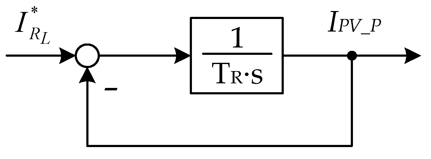
The first-order filter can also be interpreted as a current regulation loop that ensures the measured current I P V _ P matches the prescribed value I R L * from the ADC conversion as illustrated in Figure 4. The closed-loop structure in Figure 3 therefore presents the emulator as a special regulation system. For each pair θ and G, the Lookup Table assigns a distinct I–V characteristic. The role of the regulation loop is to adjust the operating point on this characteristic to the values corresponding to the load resistance R L , that is, to the values satisfying the equality V P V _ P = R L I P V _ P , regardless of the value of R L . The inertia of the control process should be as small as possible.
The proposed embedded implementation integrates a real-time control platform (dSPACE DS1103), a programmable DC source, an LUT-based photovoltaic model, and a feedback control loop with filtering. The architecture explicitly accounts for real-time constraints such as communication delays, sampling frequency limitations, and actuator dynamics.
As a result, the system provides a flexible and reliable platform for emulating photovoltaic behavior under realistic and repeatable laboratory conditions and is designed to support future integration with MPPT algorithms, power converters, and embedded control strategies [9,24].

4. Experimental Results and Validation of the Proposed PV Emulator

The experimental validation of the proposed PV emulator was carried out using the real-time embedded platform described in Section 3. The system consists of a dSPACE DS1103 control board, a programmable DC power source, and a resistive load.
The photovoltaic model is implemented using an LUT approach, while the control algorithm is executed in real time within the dSPACE environment. Environmental parameters such as irradiance and temperature are varied through the host computer interface to emulate different operating conditions.
The modelling of the programmable source-load assembly is based on the fact that the programmable source EXTECH 382280 can be considered as a black box, since its internal electrical circuit is unknown. The following aspects are documented:
(i)
the maximum permissible current and voltage values at its output terminals, and
(ii)
the fact that control commands can be applied through the serial interface at discrete time intervals of h d S 0.1   s .
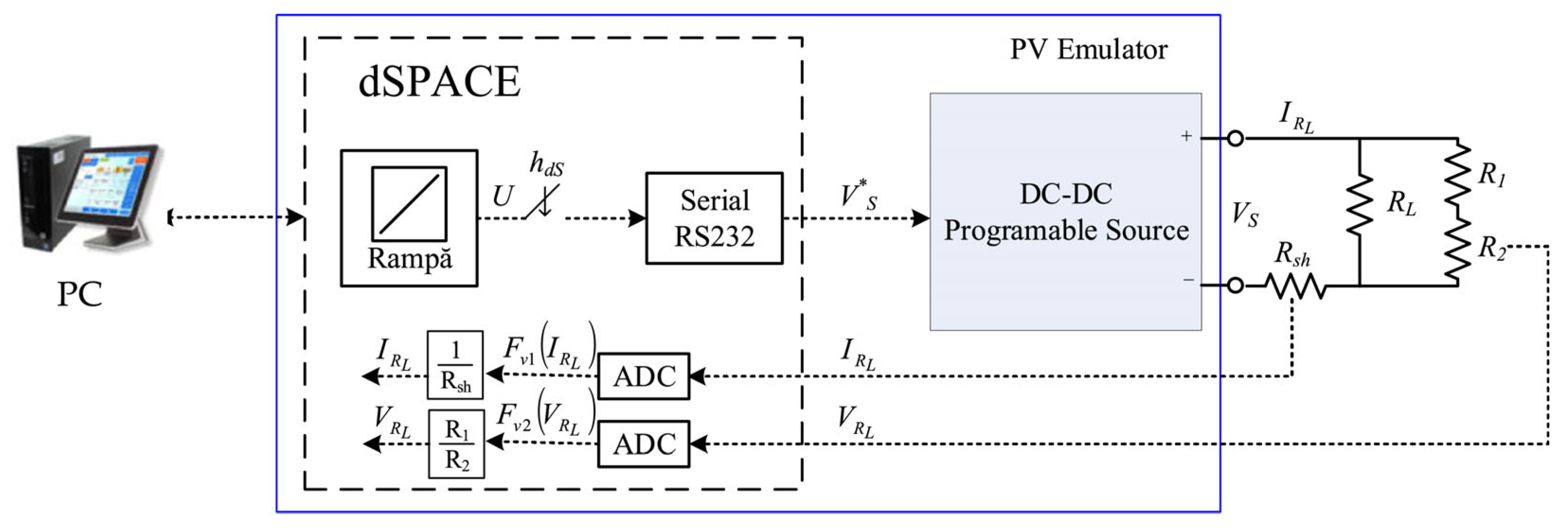
In this context, mathematical modelling of the source and identification of its parameters were required. The working scheme considered is shown in Figure 5. In parallel with the load resistor R L , a voltage divider consisting of resistors R 1 and R 2 is connected. These resistors are dimensioned so that the additional load they introduced is negligible compared to R L ( R 1 + R 2 R L ). Using the shunt resistor R s h and the resistor R 2 , both the current and the voltage across the load, I R L and V R L , are determined.
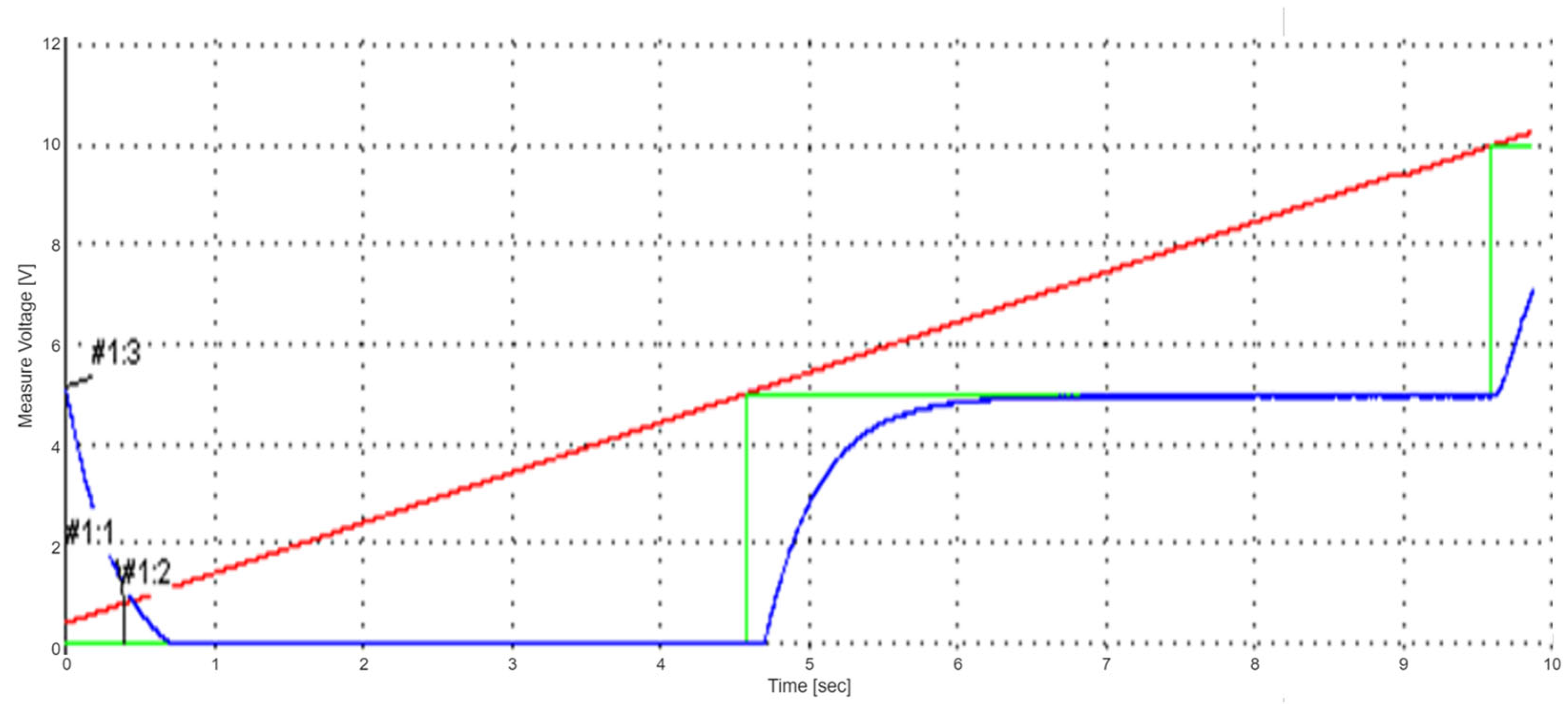
The setup shown in Figure 5 is an open-loop structure commanded by a ramp signal with a slope of 1 V/s. This signal is generated by the dSPACE module and discretized with a step of h d S . The experimental scenarios consisted of determining the system’s response, I R L ( t ) and V R L ( t ) , for different values of load resistance R L and discretization step h d S . In this study, only the results for constant R L = c o n s t . , while for constant h d S { 1 , 3 , 5 } s are presented. The case where R L is varied, with h d S being constant, will be presented in future work. Due to the limitation of the voltage range at the input of the dSPACE board ADC to [−10 V, 10 V] interval, and the required measure voltages in the [0 V, 23 V] range, a voltage divider defined by with R 1 = 24.9 KΩ and R 2 = 4.87 KΩ was used.
The programmable source is commanded through a serial signal. In an analogue control signal interpretation, the command corresponds to a staircase signal generated by feeding a ramp signal U to a zero-order hold element. Conceptually, with a Simulink implementation, this signal can be obtained by directly connecting a hold block to the ramp signal U and setting the sampling period to ∆t. In this context, in Figure 5 the signal V S * corresponds precisely to this staircase signal.
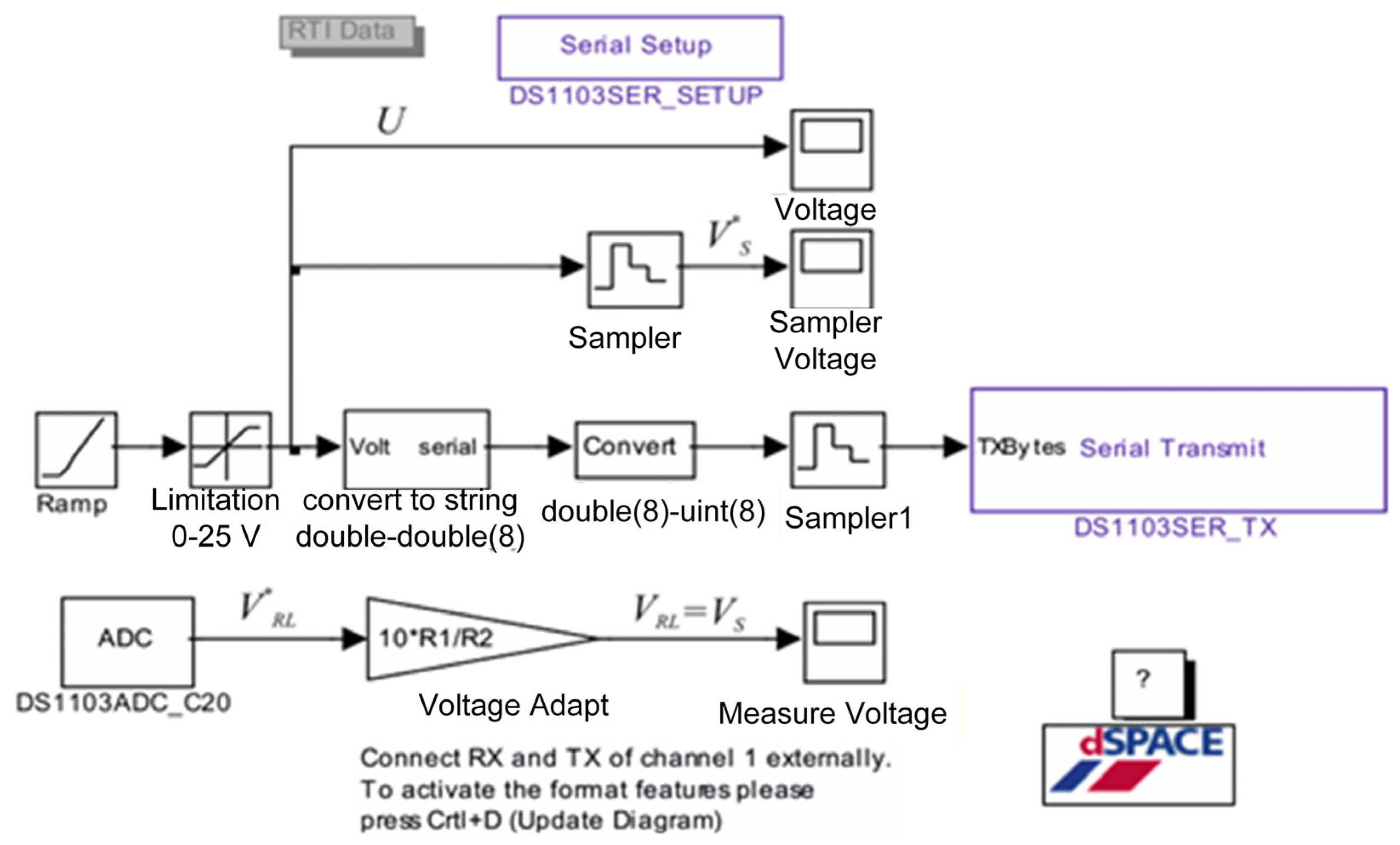
The scheme in Figure 4 was practically implemented as shown in Figure 6. The Simulink blocks used are:
  • Serial Setup—configures the serial communication according to the source communication protocol [27]. Settings: Baud rate 9600, Parity none, Data bits 8, Stop bits 1, Flow control none.
  • Transform to string—converts the control voltage value into the character string required by the source command. For example, for 3.45 V the string sent is: “V 03.450 <cr>”, where “V” is the voltage programming code and <cr> (Carriage Return, ASCII code 13) is the command terminator.
  • Convert—transforms the numerical representation from double (64-bit) to 8-bit unsigned integer.
  • Limiter—constrains the voltage command to the range [0 V, 25 V] to avoid programming the source with out-of-range values.
  • Voltage_Adapt—scales the measured ADC voltage to the actual load voltage V L , by multiplying with the factor corresponding to the dSPACE board scaling and the divider ratio R 1 + R 2 R 2 .
  • Sampler—samples the signals with period Δt.
The measured signals during experiments are presented in Figure 6.
Figure 6. Simulink implementation on the dSPACE module of the scheme in Figure 5.
Electronics 15 01765 g006
The results obtained for different values of R L and h d S are summarized by the experiments presented below.
Beyond its technical validation, the proposed emulator also supports sustainable research practices. By avoiding repetitive outdoor testing and the physical degradation of PV modules, it reduces material waste and the associated energy expenditure during experimental phases. This approach contributes to the sustainable development goals (SDG 7—Affordable and Clean Energy, and SDG 12—Responsible Consumption and Production).

5. Experimental Results with the Proposed PV Emulator

The experimental results obtained using the proposed PV emulator confirm its capability to accurately reproduce the electrical behavior of real PV modules under various operating conditions. The implementation based on a programmable DC source and a dSPACE real-time platform ensures stable operation, deterministic execution, and compatibility with embedded control applications.

5.1. Summary of Experimental Findings

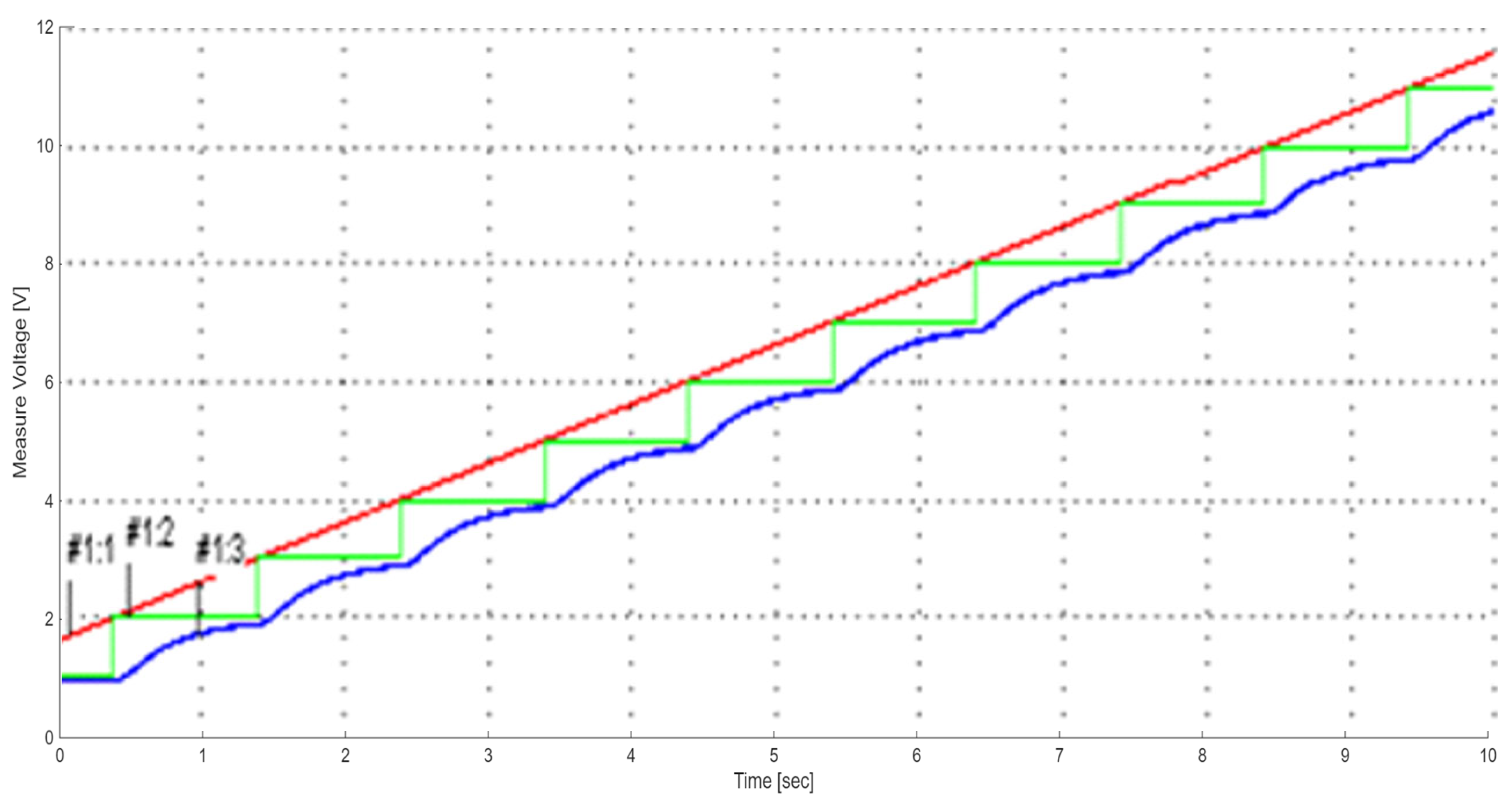
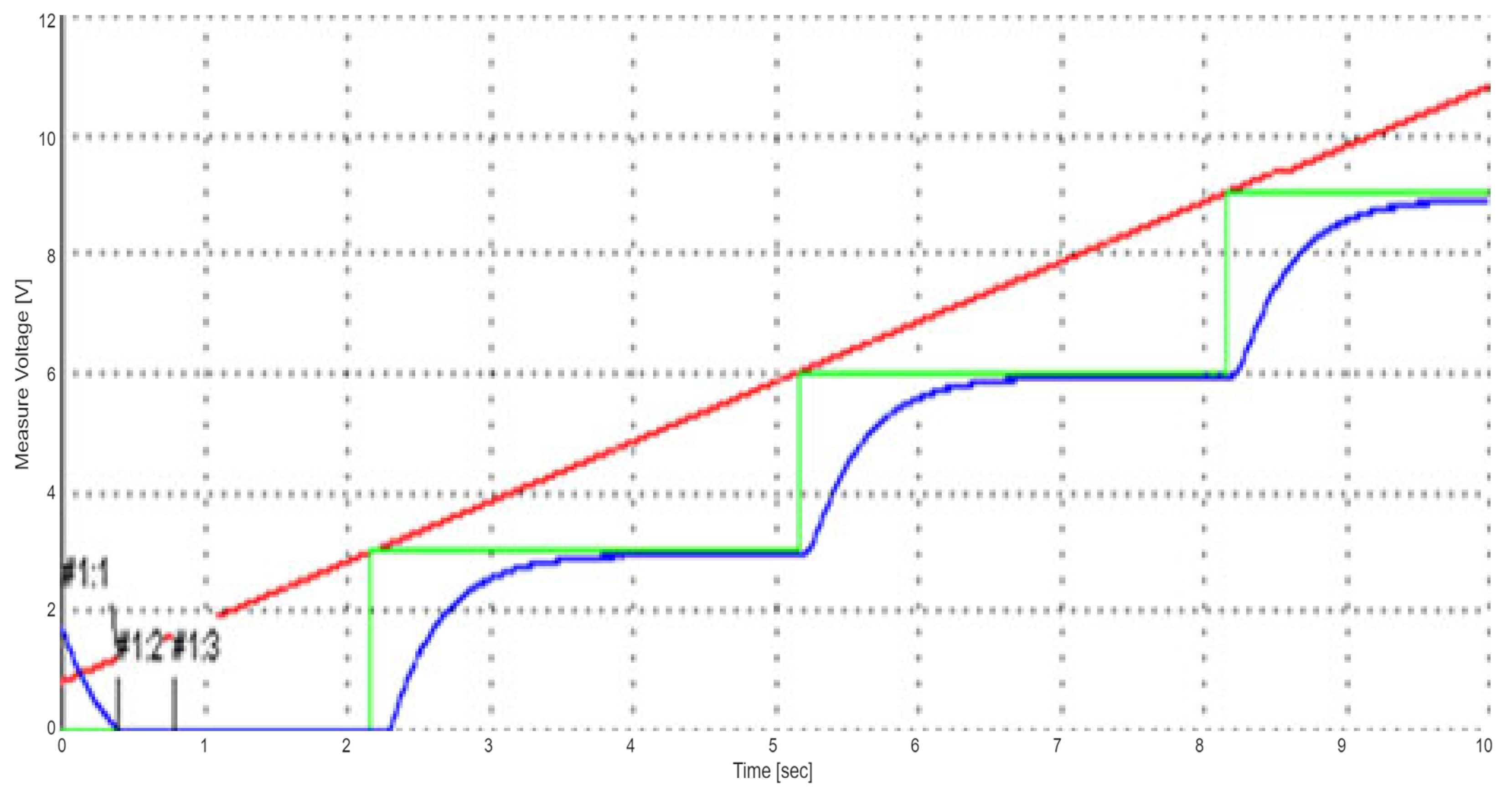
The analysis of the recorded signals, presented in Figure 7, Figure 8 and Figure 9, highlights the influence of the sampling period on the emulator response.
From the analysis of these results, the following findings can be drawn:
  • The relationship between the signals V R L and V S * is inertial, and it is not influenced by the load resistance R L . It is characterized by both a time delay (a time constant, T P ) and a dead time τ p , having the form:
    T P V ˙ S ( t ) + V S ( t ) = V S * ( t τ P )
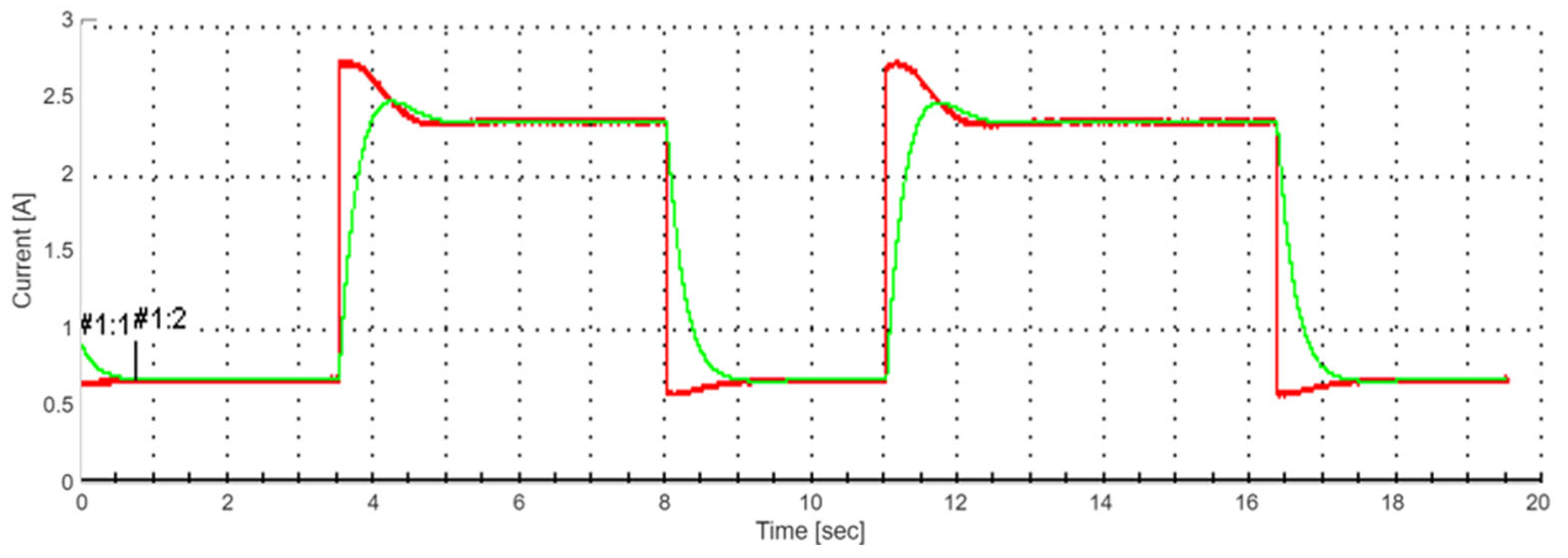
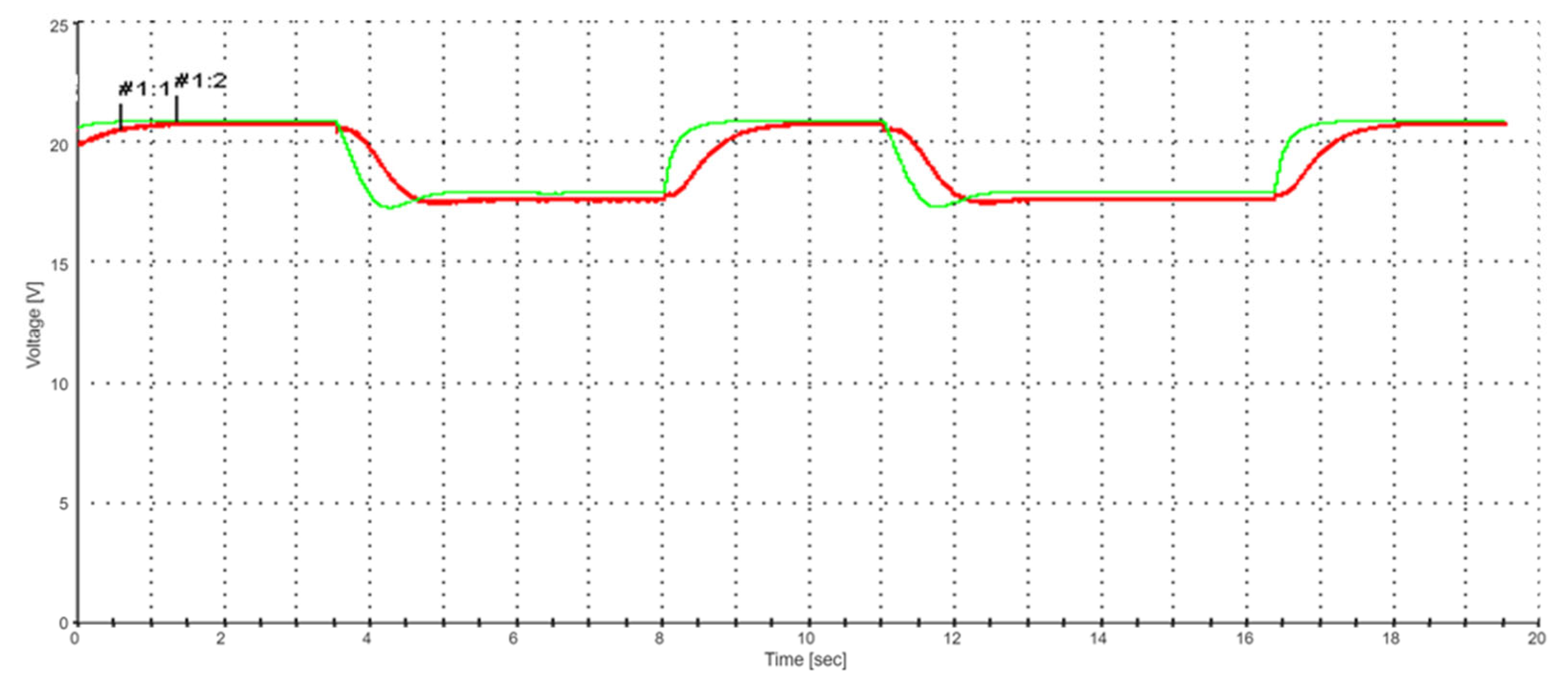
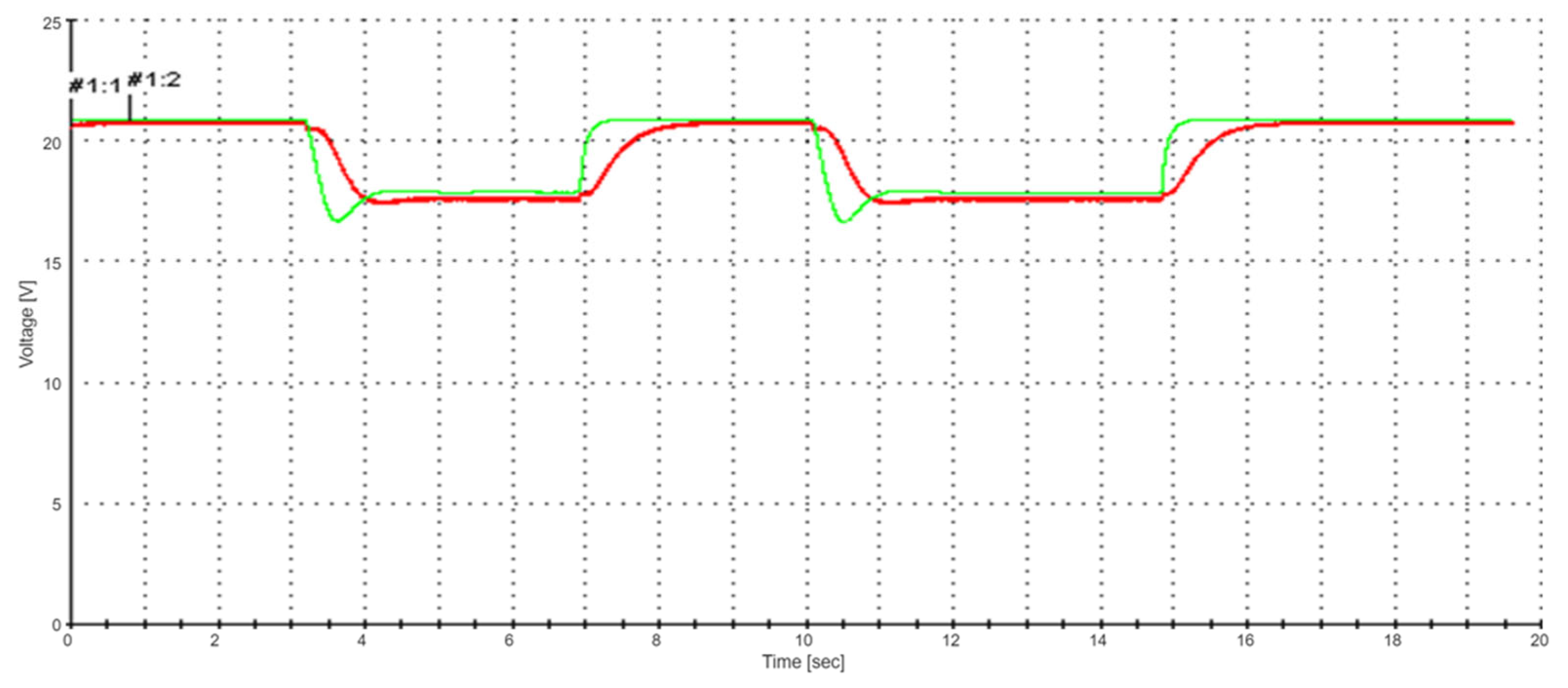
  • The time constant T P does not depend on R L or the sampling step h d S and is a practical invariant of T P 0.5 . When two programmable voltage sources are commanded synchronously and connected in series to create emulators for panels with higher terminal voltages, the time constant is observed to double (see Figure 10 and Figure 11).
  • The dead time τ p is a random variable of the programmable source, taking values in the interval [0, 0.1] s. Based on this, as a first approximation, one can consider τ p = 0 s and operate with the following model:
    T P V ˙ S ( t ) + V S ( t ) = V S * ( t ) ,   T P = 0.5   s ,
    and in a second approximation, one can consider τ P = 0.05 s, operating with the model:
    T P V ˙ S ( t ) + V S ( t ) = V S * ( t τ P ) ,   T P = 0.5   s ,   τ P = 0.05   s
  • Given that the load circuit is resistive and therefore non-inertial, under the assumption that R s h < < R L < < R 1 + R 2 , Vs, we can consider that:
    V S ( t ) = R L I R L ( t )
    T P d I R L ( t ) d t + I R L ( t ) = 1 R L V S * ( t τ P )
    with T P = 0.5 s, τ P = 0 in the first approximation and with T P = 0.5 s, τ P = 0.05   s in a second approximation.

5.2. Dynamic Behavior Under Load Variations

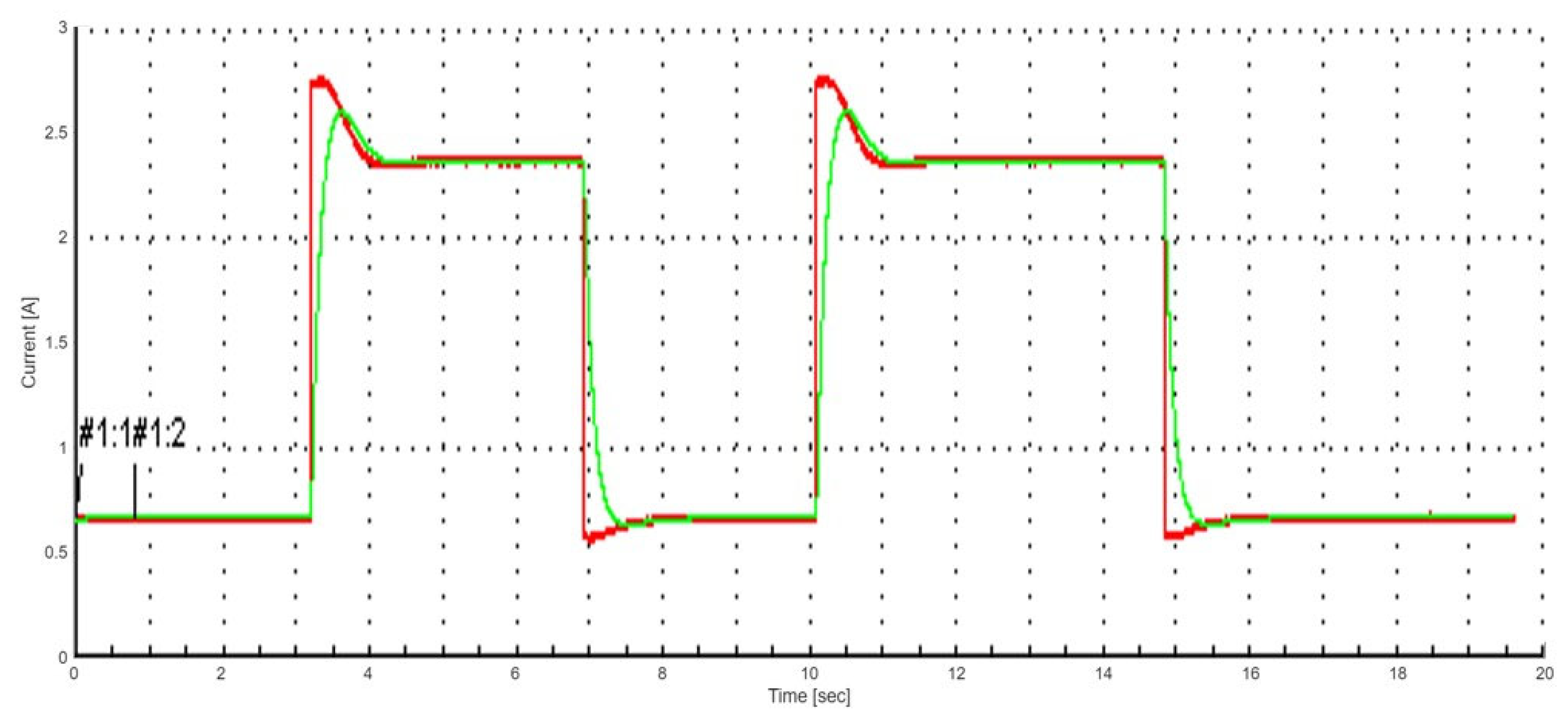
The effect of load variation on the emulator response is illustrated in Figure 10, Figure 11, Figure 12 and Figure 13.
In the diagram shown in Figure 2, the signal V S * plays the role of the signal V P V _ P * . Furthermore, given that the RS232 serial block transmits a numerical signal practically instantaneously, we can consider that the signal V S * also plays the role of the signal V P V _ P * . Consequently, we will consider the following equation as the model for the programmable source–load circuit:
T P d I R L ( t ) d t + I R L ( t ) = 1 R L V P V _ P * ( t τ P )
with T P = 0.5 s, τ P = 0 s on the first approximation.
The experimental results confirm that the emulator maintains stable operation across all tested load conditions. The programmable source exhibited a consistent time constant of approximately 0.5 s, independent of the load resistance R L and the sampling step h d S , with a random dead time varying between 0 and 0.1 s. The invariance of the time constant with respect to the load confirms that the system dynamics are dominated by the programmable source rather than by the external circuit. A detailed stability analysis is presented in Section 5.3.

5.3. Stability Analysis

The stability of the closed-loop emulator system was analyzed considering the structure shown in Figure 2, which consists of a linear dynamic element (the programmable source, modeled as a first-order system with time constant T P ≈ 0.5 s and dead time τ P ∈ [0, 0.1] s) in feedback with the nonlinear static mapping defined by the LUT-based PV model.
The nonlinear element corresponds to the I–V characteristic of the two-diode model, which is a monotonically decreasing function of current in the operating region ( V / I < 0 ). As demonstrated in [36], for any constant voltage input, the two-diode model equation defines a strictly increasing function with a unique zero crossing, guaranteeing the existence and uniqueness of a stable equilibrium point for each operating condition.
Based on this structure, a stability analysis using the Popov absolute stability criterion has been carried out by the authors. The analysis confirms that the closed-loop system satisfies the Popov stability condition for the identified range of system parameters, including the experimentally determined time constant and dead time of the programmable source. The detailed derivation and graphical interpretation of the Popov criterion applied to the proposed emulator architecture will be presented in a forthcoming dedicated publication. However, the key conclusion is that the system is absolutely stable for all resistive load conditions within the tested operating range.
This analytical result is fully consistent with the experimental observations reported in Section 5.1 and Section 5.2: no oscillatory behavior, overshoot, or divergence was observed in any of the tested scenarios, across different load resistances ( R L ∈ {10, 35} Ω), sampling periods ( h d S ∈ {1, 3, 5} s), and filter time constants ( T R ∈ {0.125, 0.25} s).
It is noted that the present stability analysis applies to passive resistive loads. The extension to active loads, such as DC–DC converters with input capacitors, requires additional analysis and will be addressed in future work.

5.4. Comparative Analysis and Experimental Performance

A summary of representative PV emulator approaches is provided in Table 2.
A comparison of photovoltaic models used in emulation is presented in Table 3.
The developed PV emulator demonstrates robust real-time performance and accuracy. Future work includes FPGA acceleration and hybrid PV–battery system integration.
A summary of the experimental results obtained using the proposed system is presented in Table 4.

5.5. Final Remarks and Future Work

The developed PV emulator demonstrates robust real-time performance, accurate reproduction of PV characteristics, and stable operation under varying resistive load conditions. The use of a lookup-table-based implementation combined with a real-time embedded platform enables efficient and flexible system design. Furthermore, the explicit consideration of communication delays and hardware dynamics enhances the practical applicability of the emulator.
It is acknowledged that the current experimental validation is limited to resistive loads, which was a deliberate choice to isolate and characterize the emulator behavior independently of downstream control or conversion stages. The platform architecture, however, is fully compatible with active load interfaces and can be directly extended to support such applications.
Future work will focus on: (i) experimental validation with DC–DC converters implementing MPPT algorithms (e.g., Perturb and Observe, Incremental Conductance), including comparison with real PV panel behavior under equivalent conditions; (ii) FPGA-based acceleration for improved dynamic performance; (iii) integration with hybrid PV–battery systems; and (iv) extension to grid-connected scenarios.

6. Conclusions

This paper presented the design, implementation, and experimental validation of a real-time embedded photovoltaic (PV) emulator based on the two-diode model and implemented using a dSPACE DS1103 platform.
The proposed system enables accurate reproduction of PV current–voltage characteristics under varying environmental conditions, while ensuring deterministic execution and stable operation in a real-time embedded environment. The use of a programmable DC source combined with a lookup-table-based modelling approach provides an efficient and flexible solution for laboratory testing of PV systems.
The hardware architecture, based on a programmable DC source interfaced with the dSPACE controller, enables high-fidelity reproduction of I–V characteristics while maintaining flexibility for testing different PV technologies. The inclusion of accurate sensing and feedback loops ensures that the emulator output tracks the theoretical model. The modular architecture is designed to allow researchers to evaluate, in future extensions, advanced MPPT techniques, inverter topologies, and hybrid energy systems under controlled and repeatable conditions.
In addition, the implementation of multi-level control strategies, comprising inner-loop converter regulation, outer-loop PV modelling, adaptive parameter identification, and environmental simulation, has been demonstrated to significantly improve emulator performance. The ability to replicate varying environmental conditions, such as irradiance and temperature changes, demonstrates that the emulator constitutes a reliable and safe research platform. Extension to more complex scenarios, including partial shading patterns and rapid transients, is planned for future work.
Simulation and experimental validation confirm the accuracy of the proposed emulator approach. The two-diode model achieved 1.2% error using GA-optimized parameters. In addition to the results presented earlier, further simulations were carried out to investigate the performance of the emulator across varying temperatures (15–60 °C) showed that the model maintains high accuracy, with deviations below 2% under all tested conditions. These results further validate the suitability of the selected model for real-time applications.
The comparison of PV models highlighted that the two-diode model offers the best trade-off between accuracy and computational complexity for real-time applications. When combined with optimization-based parameter identification and lookup-table implementation, the model enables accurate emulation with reduced computational burden.
The proposed architecture provides a reliable platform for reproducing photovoltaic electrical behavior under controlled and repeatable laboratory conditions, suitable for future integration with MPPT algorithms, power electronic converters, and embedded control strategies.
Future work will focus on improving dynamic performance through high-speed embedded platforms (e.g., FPGA-based implementations), as well as extending the emulator to support hybrid energy systems and advanced control strategies.

Author Contributions

Conceptualization, F.-M.P.; Methodology, F.-M.P. and A.-A.P.-L.; Software, F.-M.P.; Validation, F.-M.P. and A.-A.P.-L.; Formal analysis, V.E.B.; Investigation, A.-A.P.-L.; Resources, F.-M.P.; Data curation, F.-M.P. and A.-A.P.-L.; Writing—original draft, F.-M.P. and A.-A.P.-L.; Writing—review & editing, F.-M.P., A.-A.P.-L. and V.E.B.; Visualization, A.-A.P.-L.; Supervision, F.-M.P. and V.E.B.; Project administration, F.-M.P.; Funding acquisition, F.-M.P. All authors have read and agreed to the published version of the manuscript.

Funding

This research was funded by Aurel Vlaicu University of Arad, grant number 5578/03.06.2025, through national scientific research project “Evaluation, Modelling, and Simulation of Advanced Soft Computing Methods in the Field of Electricity Generation Using Photovoltaic Panels”, coordinated by Dr. Eng. Flavius-Maxim Petcut as project director.

Data Availability Statement

The original contributions presented in this study are included in the article. Further inquiries can be directed to the corresponding authors.

Conflicts of Interest

The authors declare no conflict of interest.

Abbreviations

The following abbreviations are used in this manuscript:
ADCAnalogue-to-Digital Converter
crCarriage Return
DSPDigital Signal Processor
I–VCurrent–Voltage
I 0 The reverse saturation current
I 01 The reverse saturation current diode 1
I 02 The reverse saturation current diode 2
I 03 The reverse saturation current diode 3
I p h Photocurrent
I P V _ P Current of Photovoltaic Panel
FPGAField-Programmable Gate Array
GSun radiation
GAGenetic Algorithm
HILHardware-In-the-Loop
h d S Discretization step
MPPTMaximum Power Point Tracking
n The diode ideal factor
n 1 The diode 1 ideal factor
n 2 The diode 2 ideal factor
n 3 The diode 3 ideal factor
PCPersonal Computer
PVPhotovoltaic
P–VPower–Voltage
R 1 Voltage divider consisting of resistors
R 2 Voltage divider consisting of resistors
R L Resistive Load
R p The shunt resistances (or parallel resistance)
R s The Series Resistance
SDMSingle-Diode Model
secSeconds
TDMTwo-Diode Model
ThDMThree-Diode Model
UThe ramp signal to a zero-order hold element
VThe voltage programming code
V L Actual load voltage
V P V _ P Voltage of Photovoltaic Panel
V P V _ P * Board using the Voltage control signal
V S DC voltage
V t The thermal voltage
θTemperature

References

  1. International Energy Agency Photovoltaic Power Systems Programme (IEA-PVPS). Snapshot of Global PV Markets 2025; IEA-PVPS: Paris, France, 2025; Available online: https://iea-pvps.org/wp-content/uploads/2025/04/Snapshot-of-Global-PV-Markets_2025.pdf (accessed on 20 September 2025).
  2. Pytel, K. Evaluation of Environmental Factors Influencing Photovoltaic Power. Energies 2025, 18, 2113. [Google Scholar] [CrossRef]
  3. Al Humairi, A.; El Asri, H.; Al Hemyari, Z.A.; Jung, P. A Robust Modeling Analysis of Environmental Factors Influencing the Direct Current, Power, and Voltage of Photovoltaic Systems. Electronics 2025, 14, 2647. [Google Scholar] [CrossRef]
  4. Baxevanaki, E.; Tzoumanikas, P.; Kazadzis, S. Effects of Aerosols and Clouds on Solar Energy Production. Remote Sens. 2025, 17, 3201. [Google Scholar] [CrossRef]
  5. Raza, M.A.; Rehman, S.; Ahmad, S.; Sajjad, I.A.; Bhatti, M.A. Mitigating the Impact of Partial Shading Conditions on Photovoltaic Systems. Sustainability 2025, 17, 1263. [Google Scholar] [CrossRef]
  6. Sezgin-Ugranlı, H.G. Photovoltaic System Performance Under Partial Shading Conditions: Insight into the Roles of Bypass Diode Numbers and Inverter Efficiency Curve. Sustainability 2025, 17, 4626. [Google Scholar] [CrossRef]
  7. Petcut-Lasc, A.-A.; Balas, V.E.; Petcut, F.-M. A Survey of MPPT Techniques Under Partial Shading Conditions: Evaluating the Firefly Algorithm’s Performance. In Proceedings of the 18th International Conference on Engineering of Modern Electric Systems (EMES 2025), Oradea, Romania, 29–30 May 2025; IEEE: New York, NY, USA, 2025; pp. 1–6. [Google Scholar] [CrossRef]
  8. Tahir, Z.; Ghafoor, A.; Saqib, M.A.; Khan, A.A.; Tariq, M.; Arif, S.M. A Comprehensive Review on Recent Developments in PV Emulators: Topologies, Control, and Applications. Sol. Energy 2021, 220, 102–129. [Google Scholar] [CrossRef]
  9. Ayop, R.; Tan, C.W. A Comprehensive Review on Photovoltaic Emulator. Renew. Sustain. Energy Rev. 2017, 80, 430–452. [Google Scholar] [CrossRef]
  10. Krismadinata; Anggraini, S.; Asnil; Mulya, R.; Syafii; Fahmi. Design and Implementation of Photovoltaic Emulator for Testing of Photovoltaic Energy Conversion System. Int. J. Electr. Electron. Eng. 2025, 12, 191–200. [Google Scholar] [CrossRef]
  11. Villalva, M.G.; Gazoli, J.R.; Filho, E.R. Comprehensive Approach to Modeling and Simulation of Photovoltaic Arrays. IEEE Trans. Power Electron. 2009, 24, 1198–1208. [Google Scholar] [CrossRef]
  12. Ishaque, K.; Salam, Z.; Taheri, H. Simple, Fast and Accurate Two-Diode Model for Photovoltaic Modules. Sol. Energy 2011, 85, 1938–1949. [Google Scholar] [CrossRef]
  13. Cubas, J.; Pindado, S.; De Manuel, C. Explicit Expressions for Solar Panel Equivalent Circuit Parameters Based on Analytical Formulation and the Lambert W-Function. Energies 2014, 7, 4098–4115. [Google Scholar] [CrossRef]
  14. Nguyen, X.H.; Nguyen, M.P. Mathematical Modeling of Photovoltaic Cell/Module/Arrays with Tags in MATLAB/Simulink. Energies 2015, 8, 12264–12284. [Google Scholar] [CrossRef]
  15. Mellit, A.; Kalogirou, S.A. Artificial Intelligence Techniques for Photovoltaic Applications: A Review. Prog. Energy Combust. Sci. 2008, 34, 574–632. [Google Scholar] [CrossRef]
  16. Blaabjerg, F.; Teodorescu, R.; Liserre, M.; Timbus, A.V. Overview of Control and Grid Synchronization for Distributed Power Generation Systems. IEEE Trans. Ind. Electron. 2006, 53, 1398–1409. [Google Scholar] [CrossRef]
  17. Rotar, R.; Petcut-Lasc, A.-A.; Petcut, F.-M.; Opritoiu, F.; Vladutiu, M. Failure Mode and Effects Analysis of a Microcontroller-Based Dual-Axis Solar Tracking System with Testing Capabilities. Appl. Syst. Innov. 2025, 8, 159. [Google Scholar] [CrossRef]
  18. Chouder, A.; Silvestre, S. Analysis Model of Photovoltaic Emulator Based on DC Power Supply. Renew. Energy 2010, 35, 2414–2420. [Google Scholar] [CrossRef]
  19. OPAL-RT Technologies. Real-Time Simulation for Power Electronics and Smart Grid; White Paper; OPAL-RT: Montreal, QC, Canada, 2019. [Google Scholar]
  20. Chroma ATE Inc. 62000H-S Series Solar Array Simulator. Available online: https://www.chromaate.com/eu/product/solar_array_simulator_62000h_s_series_205 (accessed on 5 April 2026).
  21. Keysight Technologies. PV8900 Series Photovoltaic Array Simulator. Available online: https://www.keysight.com/us/en/products/dc-power-supplies/dc-power-solutions/pv8900-photovoltaic-simulator.html (accessed on 5 April 2026).
  22. dSPACE GmbH. ACE Kit Pricing Sheet for Universities; dSPACE GmbH: Paderborn, Germany, 2022; Available online: https://acc2022.a2c2.org/wp-content/uploads/sites/45/2022/02/ACE_Kit_Pricing_Sheet_2022.pdf (accessed on 5 April 2026).
  23. dSPACE GmbH. Hardware-in-the-Loop Simulation for Power Electronics; Application Note; dSPACE GmbH: Paderborn, Germany, 2020; Available online: https://www.mathworks.com/products/connections/product_detail/dspace-hil-test.html (accessed on 22 March 2026).
  24. Test Equipment Depot. Extech 382280 Triple Output Programmable DC Power Supply, 40V/5A, 200W-Product Listing. Available online: https://www.testequipmentdepot.com/extech-382280-triple-output-programmable-dc-power-supply-40v5a-adj-5v2a-and-33v3a-fixed-200w.html (accessed on 5 April 2026).
  25. National Instruments. LabVIEW System Design Software; National Instruments: Austin, TX, USA, 2016. [Google Scholar]
  26. Walker, G. Evaluating MPPT Converter Topologies Using a MATLAB PV Model. J. Electr. Electron. Eng. Aust. 2001, 21, 49–55. [Google Scholar]
  27. Hohm, D.P.; Ropp, M.E. Comparative Study of Maximum Power Point Tracking Algorithms. Prog. Photovolt. Res. Appl. 2003, 11, 47–62. [Google Scholar] [CrossRef]
  28. Esram, T.; Chapman, P.L. Comparison of Photovoltaic Array Maximum Power Point Tracking Techniques. IEEE Trans. Energy Convers. 2007, 22, 439–449. [Google Scholar] [CrossRef]
  29. Merenda, M.; Iero, D.; Carotenuto, R.; Della Corte, F.G. Simple and Low-Cost Photovoltaic Module Emulator. Electronics 2019, 8, 1445. [Google Scholar] [CrossRef]
  30. Moussa, I.; Khedher, A.; Bouallegue, A. Design of a Low-Cost PV Emulator Applied for PVECS. Electronics 2019, 8, 232. [Google Scholar] [CrossRef]
  31. Harrison, A.; Alombah, N.H.; Kamel, S.; Ghoneim, S.S.M.; El Myasse, I.; Kotb, H. Towards a Simple and Efficient Implementation of Solar Photovoltaic Emulator. Eng. Proc. 2023, 56, 261. [Google Scholar] [CrossRef]
  32. El-Hameed, A.A.; Mahmoud, M.S.; Mohamed, A.H. Development of a Software-Based PV Emulator for Educational and Research Applications. Appl. Sci. 2025, 15, 2457. [Google Scholar] [CrossRef]
  33. Mekki, H.; Mellit, A.; Kalogirou, S.A.; Messai, A.; Furlan, G. FPGA-Based Implementation of a Real Time Photovoltaic Module Simulator. Prog. Photovolt. Res. Appl. 2010, 18, 115–127. [Google Scholar] [CrossRef]
  34. Panuya, P.S.; Salkuti, S.R.; Mandal, K.; Roy, M.; Kim, S.C. Design and Analysis of Digitally Operated PV Emulator Using Newton–Raphson Method. In Energy and Environmental Aspects of Emerging Technologies for Smart Grid; Springer: Cham, Switzerland, 2024; pp. 497–514. [Google Scholar] [CrossRef]
  35. Petcut-Lasc, A.-A.; Balas, V.E.; Petcut, F.-M.; Barna, C. Modelling and Identification of Two Genetic Algorithms Used for Solar Cell Parameter Extraction. In Proceedings of the 29th International Conference on Intelligent Engineering Systems (INES 2025), Palermo, Italy, 11–13 June 2025; IEEE: New York, NY, USA, 2025; pp. 21–26. [Google Scholar] [CrossRef]
  36. Petcut, F.M. Solar Cell Parameter Identification Using Genetic Algorithms. J. Control Eng. Appl. Inform. 2010, 12, 30–37. [Google Scholar]
  37. Sun, J. Small-Signal Methods for AC Distributed Power Systems—A Review. IEEE Trans. Power Electron. 2009, 24, 2545–2554. [Google Scholar] [CrossRef]
  38. Petcut-Lasc, A.-A.; Balas, V.E.; Petcut, F.-M. Real-Time Performance Evaluation of a MATLAB/Simulink-Based Residential PV System. In Proceedings of the ICCSC 2025, Fez, Morocco, 19–20 June 2025. [Google Scholar] [CrossRef]
  39. Petcut, F.M. Advanced Lookup Table for Enhanced Maximum Power Point Tracking Accuracy in Photovoltaic Systems. J. Control Eng. Appl. Inform. 2025, 27, 102–109. [Google Scholar] [CrossRef]
  40. Prakash, S.B.S.; Singh, G.S.; Singh, S.S. Modeling and Performance Analysis of Simplified Two-Diode Model of Photovoltaic Cells. Front. Phys. 2021, 9, 690588. [Google Scholar] [CrossRef]
  41. Qais, M.H.; Hasanien, H.M.; Alghuwainem, S.; Loo, K.H.; Elgendy, M.A.; Turky, R.A. Accurate Three-Diode Model Estimation of Photovoltaic Modules Using a Novel Circle Search Algorithm. Ain Shams Eng. J. 2022, 13, 101824. [Google Scholar] [CrossRef]
  42. Dolara, A.; Faranda, R.; Leva, S. Physical Modeling of Photovoltaic Arrays for Emulator Applications. Energy Convers. Manag. 2012, 59, 144–152. [Google Scholar] [CrossRef]
  43. Koran, A.; Sera, D.; Teodorescu, R. PV Emulator for Real-Time Simulation of PV Systems. In Proceedings of the IEEE ISIE, Gdansk, Poland, 27–30 June 2011. [Google Scholar] [CrossRef]
  44. Extech Instruments. Power Supply Used: EXTECH 382280; Extech Instruments: Nashua, NH, USA, 2013; Available online: https://assets.testequity.com/te1/Documents/pdf/extech/manuals/382280_UM.pdf (accessed on 10 September 2025).
Figure 1. I(V) characteristics displayed for different temperature and irradiance levels.
Electronics 15 01765 g001
Figure 2. Principal diagram of the PV emulator.
Electronics 15 01765 g002
Figure 3. Block diagram of the PV emulator—variant with measured current filtering.
Electronics 15 01765 g003
Figure 4. Block diagram of the measured current filter.
Electronics 15 01765 g004
Figure 5. Schematic diagram for identification of the programmable source–load assembly.
Electronics 15 01765 g005
Figure 7. Recorded signals U, V S * , V S in the case of signal discretization with a step of 1 s (sampling step h d S = 1 s).
Electronics 15 01765 g007
Figure 8. Recorded signals U, V S * , V S in the case of signal discretization with a step of 3 s (sampling step h d S = 3 s).
Electronics 15 01765 g008
Figure 9. Recorded signals U, V S * , V S in the case of signal discretization with a step of 5 s (sampling step h d S = 5 s).
Electronics 15 01765 g009
Figure 10. Current command θ = 25 °C, G = 600 W/m2, R L { 10 , 35 }   Ω , TR = 0.25 s, Measure Curent, Adjusted Curent.
Electronics 15 01765 g010
Figure 11. Voltage Command θ = 25 °C, G = 600 W/m2, R L { 10 , 35 } Ω , TR = 0.25 s, Measure Voltage, Adjusted Voltage.
Electronics 15 01765 g011
Figure 12. Current Command θ = 25 °C, G = 600 W/m2, R L { 10 , 35 }   Ω , T R = 0.125 s, Measure Curent, Adjusted Curent.
Electronics 15 01765 g012
Figure 13. Voltage Command θ = 25 °C, G = 600 W/m2, R L { 10 , 35 }   Ω , T R = 0.125 s, Measure Voltage, Adjusted Voltage.
Electronics 15 01765 g013
Table 1. Representative PV emulator implementations reported in the literature.
Emulator TypeImplementation
Example
Key CharacteristicsLimitationsTypical
Application
Software-Based [25,26,27,28]MATLAB/Simulink PV models [26]; LabVIEW-based implementations [25]High flexibility; low cost; easy model modification; suitable for rapid prototyping and algorithm testingCannot supply real current/voltage; limited to offline simulationsAlgorithm development; theoretical MPPT analysis [27,28]
Hardware-Based [29,30,31,32]Programmable DC power supplies [29]; DC–DC converter-based emulators [30,31]; software-driven PV emulators [32]Real-time current and voltage output; direct interface with physical loads; suitable for experimental validationLimited bandwidth and dynamic response; high cost of high-performance equipmentMPPT validation; inverter and power converter testing
Hybrid (HIL) [19,24,33,34]dSPACE-based systems [24]; OPAL-RT platforms [19]; FPGA-based simulators [33]; digitally controlled emulators [34]Combines real-time simulation with hardware; high fidelity; supports hardware-in-the-loop testingHigh complexity; expensive; requires specialized expertiseResearch laboratories; industrial prototyping; embedded control validation
Table 2. Summary of representative PV emulator implementations.
Approach Advantages Limitations Typical
Application
Reference
Software-based emulator (MATLAB/Simulink, LabVIEW)Flexible, low cost, easy to modify; suitable for fast prototyping and algorithm testingLimited accuracy at low irradiance; cannot supply real current/voltage; restricted to simulation environmentsAlgorithm development, theoretical MPPT studies[19,25,26]
Hardware emulator, using DC–DC converterFast response, suitable for MPPT testing; direct interaction with loadsIncreased system complexity; higher implementation cost; design effort requiredMPPT validation, inverter testing[18,29,32]
FPGA-based real-time emulatorHigh accuracy, parallel processing capability; very fast responseRequires FPGA expertise, high development costInverter evaluation, PV system testing[33]
DSP-based hardware emulator
Accurate real-time reproduction, modularity; good compromise between performance and flexibilityDSP programming complexity; limited scalability for complex modelsInverter evaluation, PV system testing[18,34]
Microcontroller-based emulatorLow cost, easy to implement; good compromise between performance and flexibilityLimited computational capability; reduced accuracy for complex modelsEducational setups, low-power PV tests[10,32]
Hybrid HIL (dSPACE/OPAL-RT)Combines real-time simulation with hardware; high fidelity; suitable for embedded validation High complexity, expensive, requires specialized tools and expertiseResearch laboratories, industrial prototyping[19,24]
Comparative studies (software, hardware, hybrid)Comprehensive evaluation of emulator architectures; benchmarking capabilitiesNot focused on a specific implementation; limited experimental validationBenchmarking architectures[8,9]
Table 3. Comparison of PV Models for Emulation.
ModelAccuracyComputational ComplexitySuitability for Real-TimeReference
Single-DiodeModerate (error ~5%); suitable under standard conditions; reduced accuracy under low irradiance and partial shadingLowHigh[11,13,14]
Two-DiodeHigh (error ~1.2%); improved accuracy due to inclusion of recombination effectsModerateOptimal trade-off between accuracy and complexity[12,35,36]
Three-DiodeVery High (error ~0.8%); improved accuracy due to inclusion of recombination effectsHighLimited; constrained by higher computational requirements[12,35,40,41]
Table 4. Summary of experimental results with Extech source and dSPACE.
ExperimentSampling
Step (s)
Load
(Ω)
Time
Constant (s)
Error
(%)
Stability
1180.51.8Stable
2380.51.5Stable
3580.51.2Stable
Disclaimer/Publisher’s Note: The statements, opinions and data contained in all publications are solely those of the individual author(s) and contributor(s) and not of MDPI and/or the editor(s). MDPI and/or the editor(s) disclaim responsibility for any injury to people or property resulting from any ideas, methods, instructions or products referred to in the content.