Article

A Target-Oriented Shared-Control Framework for Adaptive Spatial and Kinematic Support in Mixed Reality Teleoperation


Department of Mechatronics Engineering, Graduate School of Science and Technology, Meijo University, 1-501 Shiogamaguchi, Tempaku-ku, Nagoya 468-8502, Japan
*
Author to whom correspondence should be addressed.
These authors contributed equally to this work.
Electronics 2026, 15(8), 1653; https://doi.org/10.3390/electronics15081653
Submission received: 6 March 2026 / Revised: 8 April 2026 / Accepted: 13 April 2026 / Published: 15 April 2026
(This article belongs to the Special Issue Artificial Intelligence for Cyber-Physical Systems)

Abstract

Mixed Reality (MR) teleoperation offers an intuitive interface for Human-Robot Collaboration (HRC), yet it often faces the “Embodiment Gap”—a physical and kinematic mismatch between human operators and robotic platforms. Existing MR systems primarily rely on a “direct mapping” approach, where user movements are transferred directly to the robot. This forces operators to manually adapt to robotic constraints, such as singularities and joint limits, making task performance heavily dependent on individual skill. This study proposes Mixed reality Adaptive Spatial and Kinematic support (MASK), an adaptive shared-control framework designed to bridge the “Gulf of Execution” and “Gulf of Evaluation” by separating target selection from reachability and kinematic feasibility. The MASK system integrates three core modules: (1) Target Object Identification (TOI) based on body motion features to identify the intended manipulation target; (2) a Base Relocation Module (BRI) utilizing Inverse Reachability Maps to optimize the robot’s spatial configuration; and (3) a Kinematic Correction Module (KCM) that autonomously resolves kinematic constraints through pose blending and null-space optimization. Initial experimental results suggest that MASK reduces the operator’s cognitive and physical load by shifting the burden of kinematic resolution from the human to the system. This approach enables high-precision manipulation through an intuitive interface, potentially reducing the performance gap between different levels of operator proficiency.

1. Introduction

In recent years, Human–Robot Collaboration (HRC) has seen increasing practical application in diverse fields such as manufacturing, logistics, healthcare, and disaster response. It has attracted substantial attention as a critical research area for enabling humans and robots to perform tasks cooperatively [1,2,3]. In particular, by combining human flexible judgment with the physical execution capabilities of robots, it becomes possible to simultaneously improve operational efficiency, safety, and adaptability, especially for unstructured tasks and unpredictable environmental changes that are difficult for conventional fully autonomous robots to handle [1,4,5].
However, formidable challenges remain for humans and robots to work collaboratively in the same workspace. One major issue is the lack of mutual understanding regarding intent and action. Humans find it difficult to accurately predict robot capabilities and behaviors, while robots often struggle to sufficiently interpret high-level human goals. This creates a “Gulf of Execution” and a “Gulf of Evaluation,” which impede smooth collaboration [6,7,8]. In MR-based teleoperation, this difficulty is further amplified by the embodiment gap between humans and robots, including differences in reachable workspace, kinematic structure, and joint constraints.
To address this challenge, research on Mixed Reality (MR) to map human manipulation to robots for intuitive operation has gained attention [9,10,11,12,13]. Although these studies have succeeded in improving user interfaces, many remain limited to a “direct mapping” approach, where user actions are transferred directly to the robot. Consequently, even if the user’s intended motion is infeasible or unstable for the robot, the system may still attempt to follow it without sufficient correction. As a result, the quality of the final motion currently depends heavily on the operator’s skill.
Accordingly, we argue that the embodiment gap in MR teleoperation should not be treated merely as a mapping error between human motion and robot motion, but rather as a shared-control problem in which human intent and robot-side feasibility must be jointly resolved online. From this perspective, intuitive teleoperation is achieved not only by improving the user interface, but also by allowing the robot to autonomously compensate for spatial and kinematic constraints while preserving the operator’s task-level intent. Based on this perspective, this study proposes a system called Mixed Reality Adaptive Spatial and Kinematic Support (MASK). This system goes beyond providing a mere intuitive interface; it actively harmonizes the human’s intended manipulation goal with the robot’s physical constraints. MASK integrates three key modules: Target Object Identification (TOI), which estimates the intended manipulation target from user body motion features; a Base Relocation Module based on Inverse Reachability Map (BRI), which performs reachability-aware spatial adaptation; and a Kinematic Correction Module (KCM), which resolves robot-side kinematic infeasibility through pre-grasp interpolation and null-space-based posture adjustment.
Within this framework, BRI and KCM bridge the Gulf of Execution by autonomously resolving complex spatial and kinematic constraints that would otherwise require expert-level operation skill. Simultaneously, the MR-based visual feedback within TOI and BRI reduces the Gulf of Evaluation by providing the user with a clear representation of the robot’s identified target and planned actions.
In summary, the methodological novelty of this study lies not in proposing a novel control law in isolation or adding another MR interface component, but in reformulating the embodiment gap between humans and robots as a shared-control problem in MR space. Within this formulation, human intent is expressed at the target level, while spatial and kinematic feasibility are autonomously resolved by the robotic system through target identification, reachability analysis, and null-space optimization. This structure allows users to focus on task-level target selection, while robot-specific constraints are compensated online by the system.

Contributions

The main contributions of this study are summarized in the following three points:
  • Target Object Identification (TOI) as Target-Level Guidance: We formulate human operation not as a trajectory-level control input but as target-level guidance by identifying the specific manipulation target based on body motion features. A lightweight computational method is established that adaptively switches weight vectors according to the user’s physical features and reachability, enabling geometric identification of intervention targets while minimizing the computational load on the MR device.
  • Base Relocation Module (BRI) for Reachability-Aware Spatial Adaptation: Based on the robot’s Inverse Reachability Map, this module autonomously determines an optimal base position for grasping while providing an interactive navigation mechanism that allows intuitive user modification in MR space. This approach integrates mathematical reachability guarantees with flexible path adjustment based on situational judgment, thereby eliminating cognitive load related to spatial feasibility.
  • Kinematic Correction Manipulation (KCM) for Autonomous Feasibility Resolution: We propose a Kinematic Correction Module that autonomously resolves kinematic feasibility by dynamically interpolating the hand pose obtained from user hand tracking with the robot’s optimal pre-grasp pose and adjusting joint postures via null-space optimization. Through this two-stage correction, users can perform safe and high-precision grasping operations without being conscious of the robot’s kinematic constraints.
Through the integration of these modules, the proposed system (MASK) establishes a shared-control architecture in which human operators specify task intent, while spatial and kinematic feasibility are systematically resolved by the robotic system. This departs from conventional HRC frameworks that require humans to adapt their operation to robot constraints.

2. Related Work

This section outlines the technical progress of interfaces in robot teleoperation and reviews the current state of manipulation research using Mixed Reality (MR). Furthermore, we identify the structural challenges inherent in existing MR manipulation systems and clarify the positioning of this study.
Bridging the “gap in spatial awareness” between the operator and the robot has been a long-standing challenge in robot teleoperation. In early control systems using joysticks or 2D monitors, the lack of depth information made it difficult to grasp the distance to objects or the grasping position, requiring extensive training for smooth operation [14,15].
In response, Virtual Reality (VR) and Augmented Reality (AR), which utilize three-dimensional spatial information, have been introduced. Approaches using VR [16,17] provide high immersion and are suitable for precise motion control and simulation. However, since visual information of the real environment is blocked from the user, the challenges remain regarding safety confirmation against unexpected obstacles or human contact during real-time collaborative work. On the other hand, the use of AR [18,19] offers the advantage of superimposing task information onto the real space. However, in the integration of three-dimensional manipulation inputs (such as hand tracking), the constraints exist regarding occlusion processing with the environment and depth perception.
Mixed Reality (MR) integrates these advantages, enabling interaction between the physical world and virtual objects. It is regarded as one of the most promising platforms for realizing intuitive Human–Robot Collaboration (HRC) [9,10,11,12,13].
Recent studies have further strengthened the relevance of XR/MR-based teleoperation for Human–Robot Collaboration. Wang et al. [20] provided a systematic review of XR-enabled remote HRI systems and emphasized the growing importance of intuitive interaction, multimodal assistance, and user-centered evaluation. Furthermore, recent AR/MR-based teleoperation studies have demonstrated improved spatial cognition, usability, and task performance in robot manipulation and mobile manipulator operation [21,22], supporting the practical significance of immersive assistance frameworks such as the one proposed in this study.
HRC research using MR can be broadly classified into two categories: “Information Presentation” and “Direct Manipulation.” The information presentation approach [23] focuses on improving the user’s Situation Awareness by visualizing the robot’s path planning, sensor information, and internal state within the MR space. While this direction contributes to enhancing the environmental understanding and reducing cognitive load, direct intervention or modification of the robot’s motion itself remains limited as users are primarily positioned as passive observers who lack intuitive mechanisms to correct the robot’s trajectory in real time.
Regarding the direct manipulation approach, we have proposed “Immersive Robot Teleoperation Based on User Gestures in Mixed Reality Space” (IRT-MRO) [24]. IRT-MRO is a framework integrating (i) a visualization system for robot-perspective information, (ii) a calibration mechanism based on markers and point clouds, (iii) a manipulation system based on hand tracking, and (iv) a base movement system utilizing user demonstration gestures. In pick-and-place tasks targeting bottles, it demonstrated a certain success rate of 70–80%, verifying the effectiveness of intuitive operation support and path editing using MR.
However, existing direct manipulation systems, including IRT-MRO, face a structural challenge known as the “limitations of Direct Mapping” [25]. These systems focus on transmitting human hand movements directly as target values for the robot’s end-effector position and orientation. Since humans and robots have fundamentally different joint structures and workspaces (embodiment), movements that are natural for a human often result in the robot approaching singularities or exceeding joint limits. Currently, the final quality of operation is left to the operator’s skill.
Moreover, realizing real-time adaptive intervention is technically demanding due to strict latency, accuracy, and safety/QA requirements. Such system-level bottlenecks have been systematically discussed in real-time MR-guided adaptive frameworks [26].
To mitigate this dependence on operator proficiency, the concept of shared control has been extensively explored, where a control effort is distributed between the human operator and the robot’s autonomy [6,27].
In such frameworks, the robot actively assists the human by compensating for limitations in perception, motion planning, or low-level execution, thereby improving task reliability and reducing operator burden [27,28]. A particularly important direction in this context is intent inference, in which the robot estimates the user’s intended goal and uses that estimate to generate more appropriate assistance. Prior studies have shown that intent-aware assistance can improve the legibility and efficiency of robot behavior [6].
However, applying these shared-control principles to immersive MR teleoperation remains challenging. Many existing shared-control methods assume that human inputs are provided in or near the robot’s control space, whereas MR-based manipulation often starts from human body motion and hand motion defined in the user’s own embodied space. As a result, the embodiment gap between humans and robots must be resolved together with target inference, spatial feasibility, and kinematic feasibility in a dynamic 3D environment [25].
To overcome these limitations, this paper proposes the Mixed Reality Adaptive Spatial and Kinematic Support (MASK) system, which is designed to shift MR teleoperation from passive mapping relaxation to active feasibility resolution. Unlike conventional frameworks that focus mainly on trajectory-level follow-up, MASK formulates human operation as target-level guidance. By first identifying the intended manipulation target from body motion features, the system does not merely relax mapping constraints; it actively resolves spatial and kinematic limitations online by aligning the robot’s physical configuration with the identified target. This enables the framework to systematically absorb the embodiment gap and reduce dependence on operator proficiency.
These observations motivate the need for a framework that explicitly integrates target identification, reachability-aware spatial adaptation, and kinematic feasibility within MR teleoperation.

3. Adaptive Shared-Control Architecture in Mixed Reality

The overall pipeline of MASK is as follows. First, TOI infers the user’s intended target object from body-motion features in MR space. Next, BRI computes a reachability-aware base pose and corresponding relocation plan for the selected target. Finally, KCM adjusts the end-effector pose and joint configuration online so that the grasp can be executed within the robot’s kinematic constraints. In this way, the human specifies task intent, while the system sequentially resolves spatial and kinematic feasibility through shared control.
The Mixed reality Adaptive Spatial and Kinematic support (MASK) system is designed to enhance the “high reliance on operator proficiency,” which is a notable challenge in conventional MR-based HRC systems.
In existing systems, technical constraints such as insufficient use of environmental information and lack of posture bring the situation where the user has to manipulate the robot while consciously considering its workspace and stability. In contrast, the proposed system autonomously recommended “base movements adapted to the environment” and “posture control considering kinematic constraints,” which heve been left to the operator’s skill. This enables stable and intuitive collaborative work regardless of the user’s experience.
This system is constructed as an extension and improvement of the preceding study, “Immersive Robot Teleoperation Based on User Gestures in Mixed Reality Space” (IRT-MRO) [24], aiming at resolving its inherent issues. While IRT-MRO implemented a Unity-based holographic application using HoloLens 2 (Microsoft Corporation, Redmond, WA, USA), our proposed system adopts a Unity-based pass-through application using the Meta Quest 3 (Meta Platforms, Inc., Menlo Park, CA, USA). Although both devices allow real-world objects to be reflected in the MR space, there is a notable difference in their display methods. HoloLens 2 employs an optical see-through method, allowing the user to view the real environment and virtual objects simultaneously through a transparent display; however, it has been noted for its narrow Field of View (FOV) and display brightness limitations.
In contrast, the Meta Quest 3 adopts a video pass-through method, projecting images captured by external cameras onto the display to realize a wide FOV and high-resolution display. The expanded FOV facilitates peripheral checks during robot base movements, thereby improving safety. This allows the user to obtain a more natural and immersive MR experience, enhancing environmental understanding and operational intuitiveness.

3.1. System Overview and Implementation Platform

In this study, the KUKA youBot (KUKA AG, Augsburg, Germany) is adopted as an experimental platform. This robot is a mobile manipulator equipped with an omnidirectional base, a 6-DOF manipulator, and a two-finger gripper.
The MR system was implemented using Unity (Version 2022.3.52f1, Unity Technologies, San Francisco, CA, USA) and MRTK3 (Mixed Reality Toolkit 3, Microsoft Corporation, Redmond, WA, USA), developed in compliance with OpenXR (Khronos Group, Beaverton, OR, USA) standards. The user can manipulate MR objects via hand gestures, providing an intuitive and natural input interface. Furthermore, by presenting the robot’s planned actions through MR objects, the operator can easily understand the robot’s decision-making process, improving the coordination between human and robot.
In this system, the position and posture changes of the target objects detected in a MR space, as well as the user operations, are reflected in the robot’s motion to realize smooth interaction. Additionally, the robot’s behavior is immediately fed back to the MR space, providing high-precision visual information to the operator.
The overall software architecture consists of three layers: the MR-side interface, a ROS-based middleware layer, and the robot-side control modules. The MR-side interface acquires user input such as head orientation, hand motion, and object interaction information through Unity and MRTK3, and converts them into geometric and operational data used by the support modules. These data are transmitted to the robot-side system through ROS Noetic (Open Source Robotics Foundation, Mountain View, CA, USA), where target inference, base relocation planning, and kinematic correction are executed. The resulting robot states and assistance outputs are then fed back to the MR environment, allowing the operator to observe the planned motion, target-related guidance, and execution results in real time.
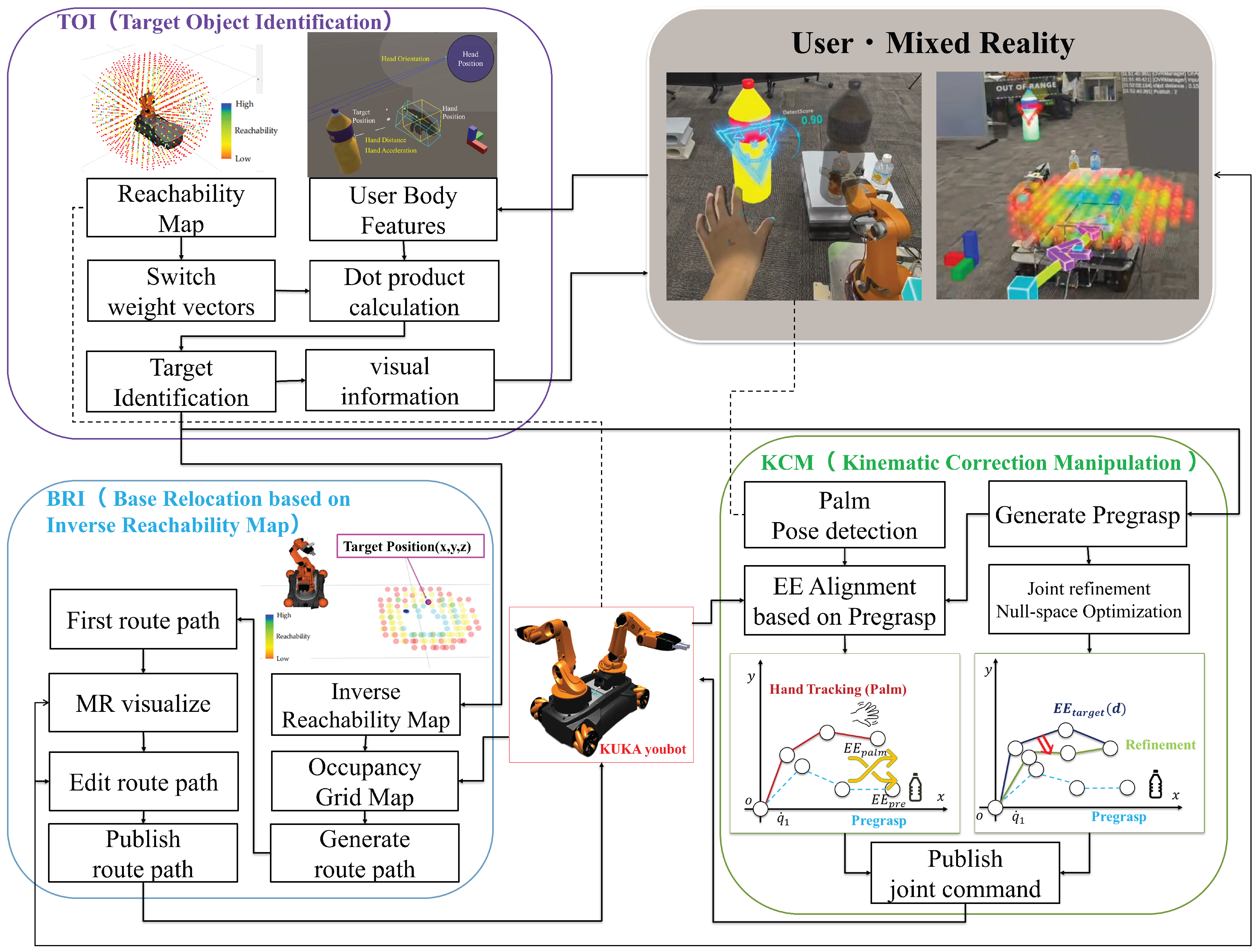
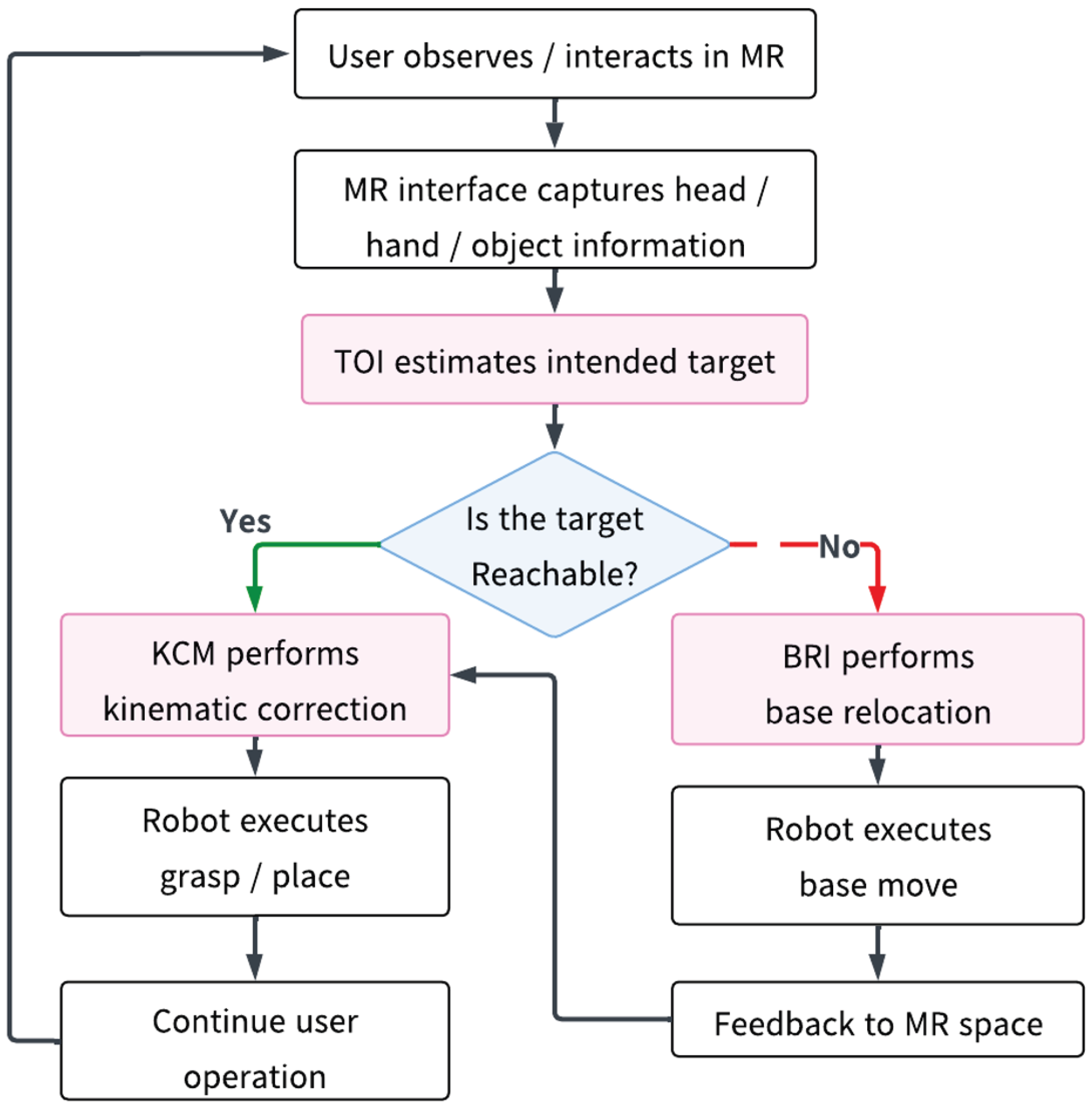
Figure 1 illustrates the overall operational flow of the proposed MASK system, showing how user input in MR is processed through target identification, reachability-based branching, base relocation when necessary, kinematic correction, robot execution, and feedback to the MR environment.
The system architecture of MASK is shown in Figure 2 which consists of the following three modules:
  • Target Object Identification Module (TOI):
    This module tracks the user’s head direction and hand movements within the MR space and extracts a geometric relationships with candidate objects as a feature. This information is processed based on an integrated score to estimate the user intended manipulation target. By comprehensively evaluating diverse features of user movement, this module enables high-precision and real-time target selection.
  • Base Relocation Module based on Inverse Reachability Map (BRI):
    This module is activated when the target bottle is outside the robot’s workspace. First, it generates an Inverse Reachability Map (IRM) based on the Reachability Map (RM) [29] to extract a set of candidate base positions that make the target position reachable. Next, it solves an optimization problem considering the IRM score and movement cost to determine the optimal base placement. Furthermore, the candidate path is visualized in the MR space, allowing for modification by the user.
  • Kinematic Correction Manipulation Module (KCM):
    The purpose of this module is to compensate for the discrepancies between the user’s operation and the robot’s physical constraints. Specifically, it integrates the reference pose obtained from the user’s hand tracking information with a pre-grasp pose that has high graspability for the robot, adjusting the joint posture using null-space optimization. This allows the user to achieve stable grasping with a natural operational sensation without being conscious of the robot’s kinematic constraints.
The integration of these modules enables an action selection according to the user’s manipulation target which was not sufficiently addressed in the conventional IRT-MRO realizing more intuitive and adaptive path planning. Moreover, as a result of enabling users operation without being conscious of the robot’s specific physical constraints, adaptive grasping actions become possible, substantially reducing the dependence on operation proficiency. This enhances smooth and stable operations even for unskilled users.

3.2. Reachability and Inverse Reachability Modeling

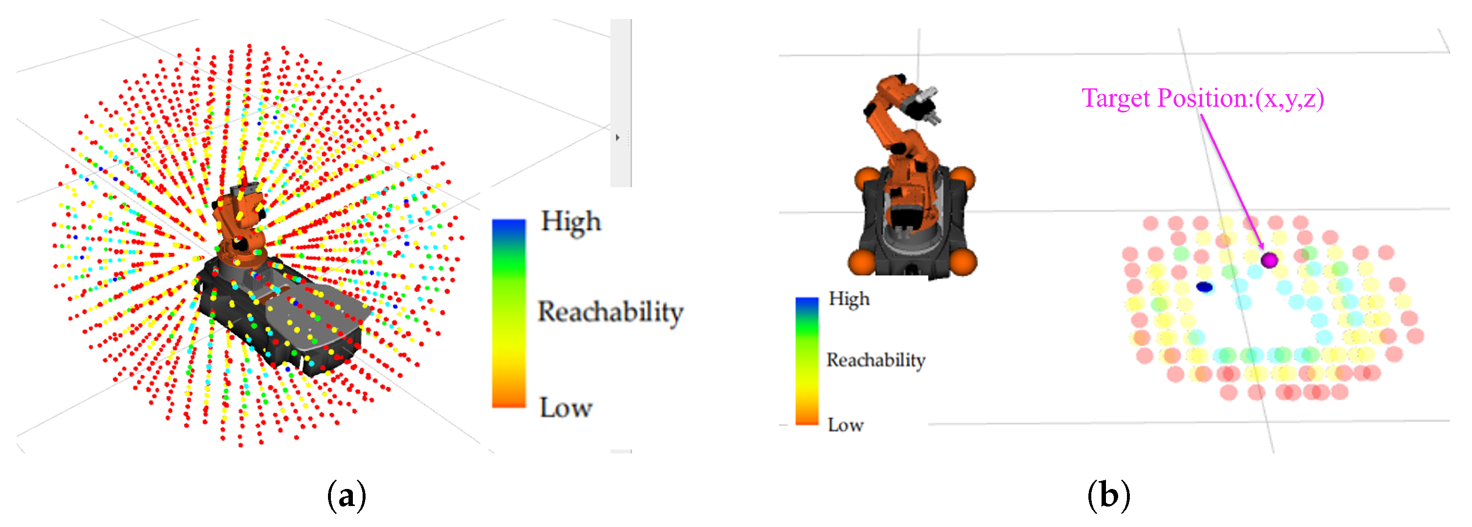
In each module of this system (particularly for information presentation in TOI and movement planning in BRI), the methods of the Reachability Map (RM) and Inverse Reachability Map (IRM) are utilized for mobile robot manipulations [29]. Figure 3 presents example visualizations of the RM and IRM.
In this study, the Reachability Map (RM) is generated in advance based on the kinematic model of the robot and its admissible joint configuration space. During execution, the Inverse Reachability Map (IRM) is dynamically constructed from the RM for the currently selected task point in order to identify feasible base positions. The visualizations shown in Figure 3 were generated in RViz: the RM visualization represents the distribution of reachable end-effector positions for a fixed base pose, whereas the IRM visualization represents the distribution of feasible base poses corresponding to a target point in the workspace.
Let b be the robot base position. The space reachable by the end-effector (EE) from that position is defined as:
R M ( b ) = { p R 3 θ s . t . F K ( θ , b ) = p } ,
where F K ( θ , b ) represents forward kinematics and θ denotes the vector of joint angles within the robot’s admissible joint space. The RM indicates the range reachable by the arm from a fixed base position.
Conversely, for a given target point p t , the set of base positions that make it reachable is defined as:
I R M ( p t ) = { b R 3 p t R M ( b ) } .
This set is referred to as the Inverse Reachability Map (IRM). The IRM provides an inverse mapping giving the set of base positions reachable to the task point.
Furthermore, in this study, to evaluate the stability and redundancy of reaching, we perform scoring using the number of inverse kinematics solutions N IK ( p ) existing for position p . Since the IRM is the inverse mapping of the RM, the score of a candidate base position b I R M ( p t ) for a target position p t is assigned as follows:
S I R M ( b ; p t ) = N IK ( p t b ) .
This allows us to handle not only “whether it can be reached” but also “how flexibly it can be reached” as a quantitative indicator. In this system, this score S I R M is used as the common metric for visualization in TOI and optimization in BRI.

3.3. Target Object Identification Module (TOI)

The TOI module aims to identify the manipulation target based on the user’s body movements. This method utilizes the following four features for identification:
  • Head Orientation: The direction the user’s face is pointing.
  • Hand Distance: Proximity based on the distance between the hand and each target.
  • Hand Acceleration: The direction and magnitude of the hand’s movement.
  • Contact: Presence or absence of physical contact (immediate decision factor).
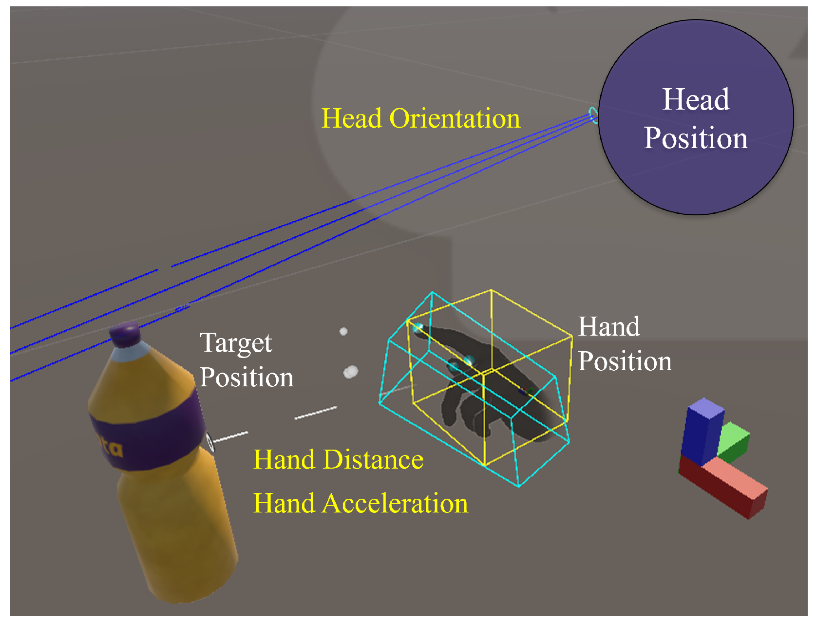
Figure 4 shows examples of these geometric relationships in the information space.

3.3.1. Feature Definition and Score Calculation

First, we define the geometric direction vectors based on the spatial positions as shown in Figure 4. Let the target position (manipulation target o i ) be p t a r , i ( t ) , and the Head Position and Hand Position be p h e a d ( t ) and p h a n d ( t ) , respectively. For each target, the normalized vectors indicating the relative direction from the user’s body parts are expressed as:
d i h e a d ( t ) = p t a r , i ( t ) p h e a d ( t ) p t a r , i ( t ) p h e a d ( t ) , d i h a n d ( t ) = p t a r , i ( t ) p h a n d ( t ) p t a r , i ( t ) p h a n d ( t )
To incorporate motion dynamics, let v h e a d ( t ) be the vector representing the user’s head forward direction, and a h a n d ( t ) be the hand acceleration vector. The unit vectors extracted by normalizing these direction components are defined as:
v ^ h e a d ( t ) = v h e a d ( t ) v h e a d ( t ) , a ^ h a n d ( t ) = a h a n d ( t ) a h a n d ( t ) .
Note that if a h a n d ( t ) 0 , we set a ^ h a n d ( t ) = 0 .
Using the above vectors, the following three continuous scores and one binary flag are calculated:
(i)
Head Orientation Score s head and Acceleration Score s accel :
By utilizing the directional vectors defined in Equation (4) and the normalized movement and orientation vectors defined in Equation (5), cosine similarity is calculated to evaluate the directional alignment between the user’s intent and each candidate target:
s head ( i , t ) = max 0 , v ^ h e a d ( t ) · d i h e a d ( t ) ,
s accel ( i , t ) = max 0 , a ^ h a n d ( t ) · d i h a n d ( t ) .
(ii)
Hand Distance Score s dis :
Defined based on the Euclidean distance between the Hand Position and the Target Position, such that closer distances yield higher values.
s dis ( i , t ) = max 0 , 1 p h a n d ( t ) p t a r , i ( t ) R max .
Here, R max is the maximum effective distance for proximity determination; scores become 0 if the distance exceeds this value. In this experiment, R max was set to 1 m .
(iii)
Contact Flag c i ( t ) :
A binary variable indicating the presence or absence of physical contact.
c i ( t ) { 0 , 1 } .
This c i ( t ) is the highest priority indicator in the final decision process described later and is not included in the feature vector for weighted score calculation.

3.3.2. Score Integration and Decision-Making Process

By aggregating the individual scores calculated in Equations (6)–(8), the feature vector summarizing the three features (excluding the contact flag) is defined as:
s ( i , t ) = [ s dis , s head , s accel ] .
The integrated score is calculated using different weightings depending on whether the target belongs to the reachable set O i n ( t ) or the unreachable set O o u t ( t ) :
S ( i , t ) = w i n · s ( i , t ) , i O i n ( t ) , w o u t · s ( i , t ) , i O o u t ( t ) .
Here, w i n and w o u t are preset weight vectors. For reachable targets, emphasizing “Hand Distance” and “Hand Acceleration” allows for robust identification without being misled by noisy head movements. Conversely, for unreachable targets, emphasizing “head orientation” correctly reflects the focus on the distant targets. This enables flexible and robust estimation tailored to the situation.
Additionally, since sudden score fluctuations due to momentary body motion jitter are expected, we introduce an Exponential Moving Average (EMA) [30] to smooth the score temporally.
S ¯ ( i , t ) = α S ( i , t ) + ( 1 α ) S ¯ ( i , t 1 ) , α ( 0 , 1 ] .
Here, S ¯ ( i , t ) represents the smoothed total score, and α is the smoothing coefficient. In this system, α was set to 0.45 , which places a slightly higher weight on the previous state ( 1 α = 0.55 ) than on the current observation. This empirical setting ensures that the identification process remains robust against high-frequency noise and momentary jitters while maintaining sufficient responsiveness to intentional changes in the user’s motion. Consequently, this suppresses temporary false detections and allows for stable target identification.
The final manipulation target is determined using “contact presence” as the priority criterion. That is:
i * ( t ) { c i ( t ) = 1 i O } .
If the contact flag is raised for any candidate, that target immediately becomes the final decision.
Otherwise, the target that maximizes the smoothed score across the entire candidate set O is selected:
i * ( t ) = arg max i O S ¯ ( i , t ) .
However, the selected target must satisfy the following threshold condition to be finalized:
S ¯ i * ( t ) , t T in , i * ( t ) O in ( t ) , T out , i * ( t ) O out ( t ) .
Here, T in and T out represent the decision thresholds for the reachable and unreachable sets, respectively. In this study, both T in and T out were set to 0.5 as a default baseline. This thresholding process ensures that the target with the highest score is not automatically adopted but is confirmed only when the targeting certainty is sufficiently high. By requiring this level of confidence, the system effectively prevents unintended robot movements caused by ambiguous user gestures or momentary tracking noise.

3.3.3. Adjustment of Information Presentation

In the TOI module, when presenting identification results to the user, the amount of visual information is adjusted to facilitate intuitive understanding while avoiding excessive visual clutter.
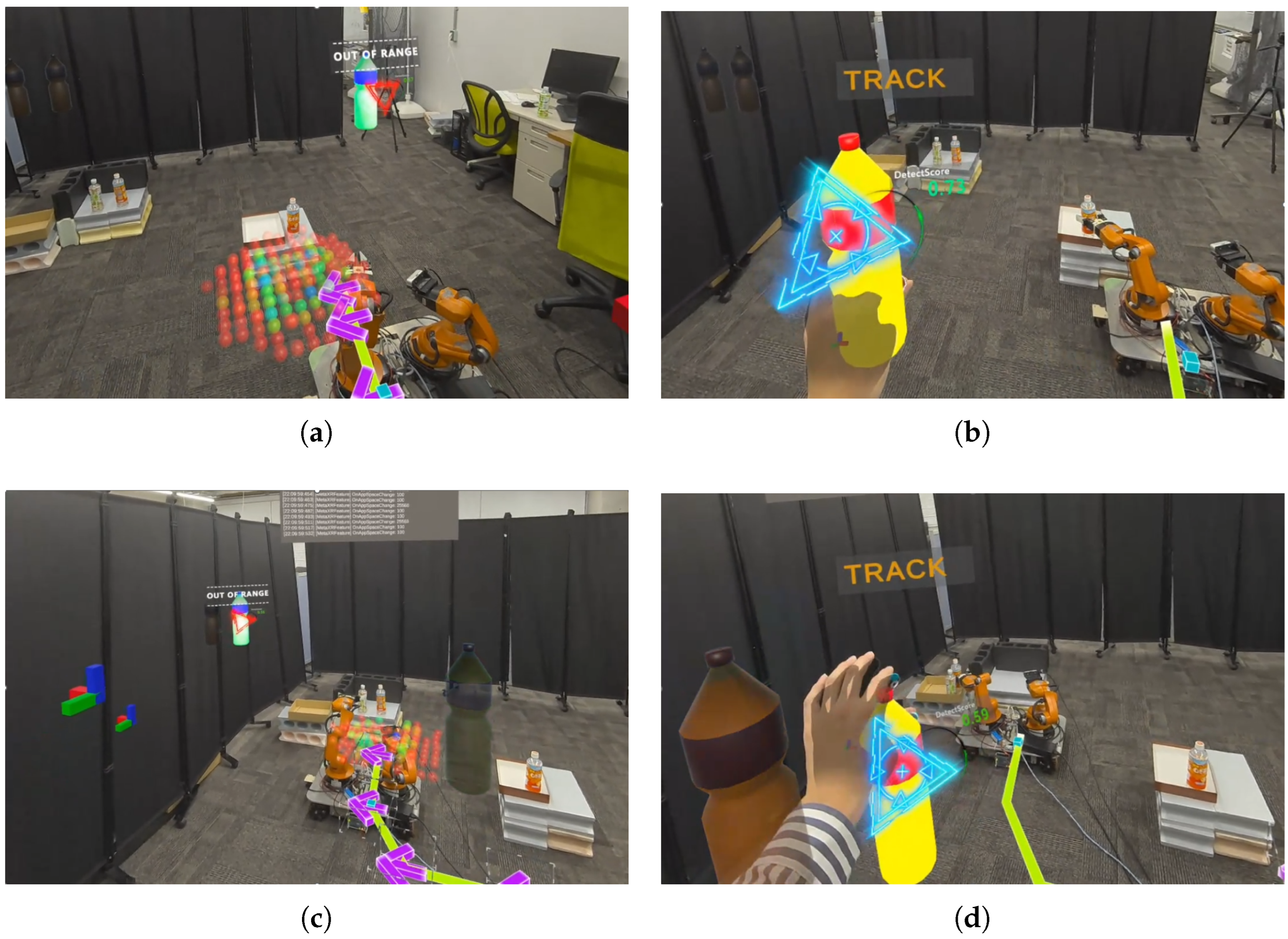
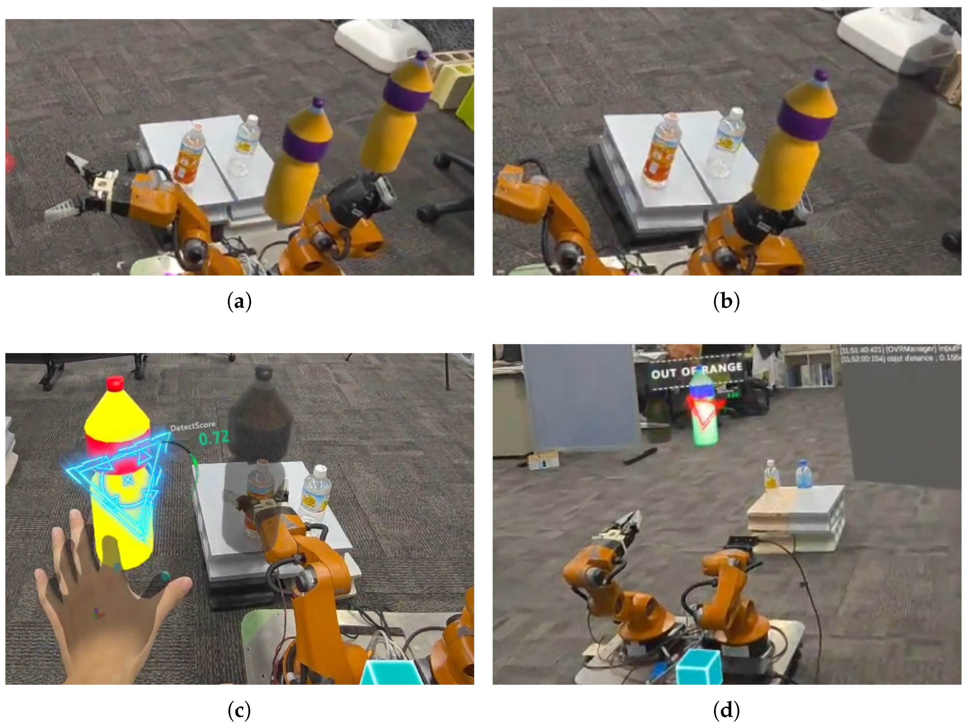
Figure 5a,b illustrates the transition of target reachability resulting from a slight positional adjustment of the mobile base. While such minimal physical displacements are often imperceptible to human operators, the MR interface explicitly communicates the resulting change in the robot’s functional workspace.
Following the logic of the Reachability Map (RM) [29], the system dynamically updates the visual properties of each target: graspable targets are rendered with their standard opaque shaders to signify availability, whereas ungraspable targets are transitioned to a semi-transparent state with reduced saturation. This visual contrast serves as an immediate indicator of task feasibility, allowing the operator to intuitively recognize the impact of base relocation without the need for complex mental spatial reasoning.
Furthermore, as shown in Figure 5c,d, when a manipulation target is determined through target identification, all objects other than the identified target are switched to a semi-transparent display. At this time, the method of UI highlighting distinguishes between graspable and ungraspable targets: the former is assigned a highlight color indicating “high manipulability,” while the latter is assigned a different hue indicating that “base movement is required.”
This two-stage adjustment of information volume allows the user to clearly distinguish between “targets the robot can currently grasp” and “targets requiring movement.” Moreover, highlighting the identified manipulation target suppresses selection errors and supports intuitive decision-making while reducing cognitive load.
In summary, the TOI module geometrically defines diverse body features such as head orientation and hand movement, and calculates an integrated score based on cosine similarity, distance, and contact indicators, thereby establishing a mechanism for high-precision and real-time target identification. Additionally, temporal smoothing suppresses temporary false detections, guaranteeing stable target identification. Furthermore, by integrating identification with adaptive visual presentation, the module enables the system to accurately identify the intended manipulation target, which serves as the foundation for the entire MASK system.

3.4. Base Relocation Module Based on Inverse Reachability Map (BRI)

Before detailing the implementation, we summarize the core idea of the BRI module. The methodological core of BRI is to resolve spatial infeasibility by transforming a target object position into a set of feasible robot base candidates through the Inverse Reachability Map (IRM), and then selecting an appropriate base pose through optimization. This optimization balances reachability quality, movement cost, and heading consistency so that the robot can relocate to a position from which the intended task becomes physically executable. The subsequent distinction between mapped and unmapped environments mainly concerns implementation and deployment conditions, whereas the core method itself is the IRM-based reachability-aware base selection.
Even if the target object is correctly identified by TOI, the task may remain infeasible if the object lies outside the robot’s current reachable range. In such cases, selecting a new base position based only on geometric proximity can lead to configurations that are technically reachable but kinematically poor, unsafe, or unnecessarily costly.
Therefore, this module adopts an approach to quickly and optimally determine “where to move to make grasping easiest” by using the IRM score S I R M defined in Equation (3). The strategy is categorized into two workflows based on the availability of environmental information: (1) System-Initialized: The system autonomously generates a path using IRM, which the user can then modify; and (2) User-Initialized: The user lesignates the initial path, and the system suggests alternative routes as the cost map is updated during operation.
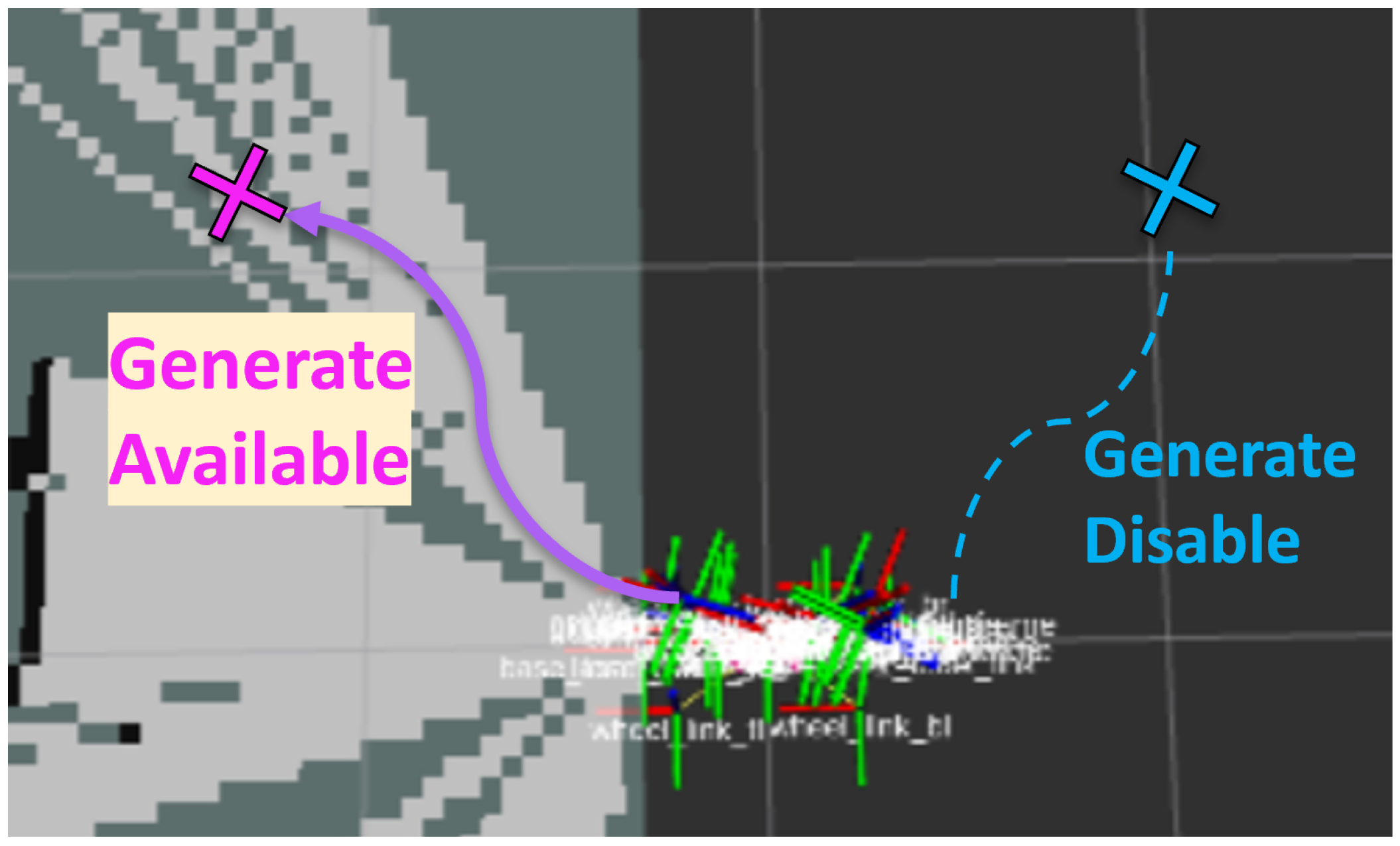
Next, we describe the algorithm for selecting the optimal base position from the candidate set I R M ( p t ) . Here, the formulation is divided into two cases depending on the availability of environmental information, as shown in Figure 6.

3.4.1. Case 1: Known Path (System-Initialized Generation)

When the environment is mapped and the movement path to the target position is known (navigable), the system takes the initiative to generate an optimal relocation route. The optimal base position b * is selected from the candidate set I R M ( p t ) by maximizing an objective function that balances manipulation quality with navigation effort:
b * = arg max b I R M ( p t ) S I R M ( b ; p t ) ω c C ( b ) ,
where S I R M ( b ; p t ) is the IRM score defined in Equation (3), representing the reachability index of the target position p t from the candidate base position b . The term C ( b ) represents the movement cost, calculated as the path length L ( Γ ( b ) ) from the initial position b 0 to b provided by the navigation system:
C ( b ) = L ( Γ ( b ) ) = 0 1 x ˙ ( s ) d s k = 1 N x k x k 1 .
Here, ω c is a weighting coefficient that adjusts the penalty for the movement distance relative to the graspability score. This formulation ensures the selection of a base position that is both kinetically favorable for the task and reachable with minimal travel.
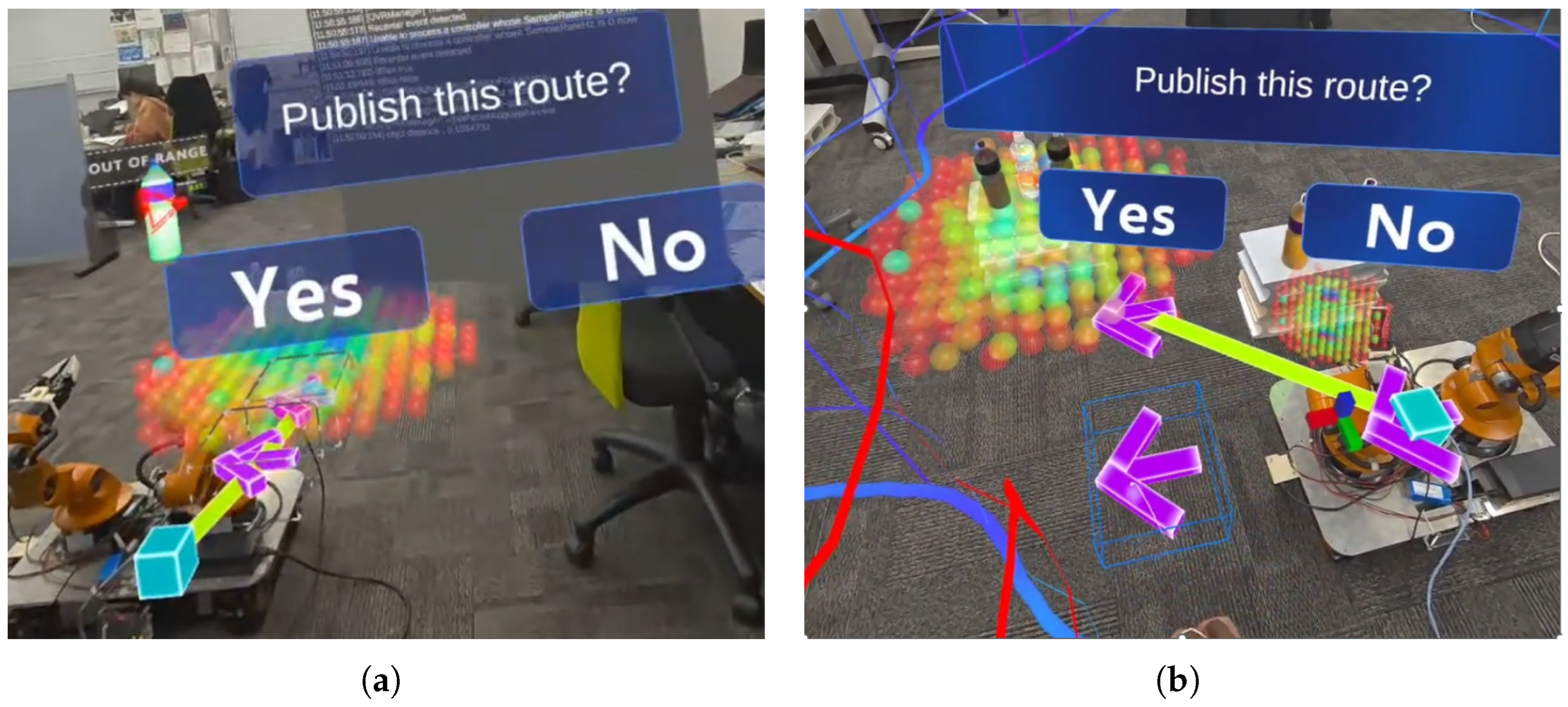
Although the system provides an autonomous proposal based on the optimization in Equation (16), the user retains final authority over the robot’s movement. The generated path and base position are presented in the MR space as an initial template, which the operator can refine to better suit the immediate task context or to avoid local obstacles not captured in the global map.
Interactive Path Refinement (Shared Autonomy Logic)
When the user manually adjusts the path in the MR space, the system treats the edited path as a reference Γ ¯ u = { x ¯ k } k = 0 N . To ensure the robot’s movement respects the user’s intent while maintaining navigation safety, we define the modified navigation cost C ( b Γ ¯ u ) for each candidate base b as follows:
C ( b Γ ¯ u ) = C ( b ) + w edit k K lock x k x ¯ k 2 ,
subject to Γ ( b ) F nav and x k = x ¯ k for k K lock . Here, F nav denotes the collision-free configuration space (navigable area), and K lock represents the set of indices for waypoints “pinned” by the user to fix specific transit points. The term w edit is the “path-editing weight”, which penalizes deviations from the user’s manual trajectory.
The system then selects the final optimal base position b by solving the following optimization problem:
b = arg max b I R M ( p t ) F nav S IRM ( b ; p t ) ω c C ( b Γ ¯ u ) ω ψ Δ ψ ( b ) 2 ,
where S IRM ( b ; p t ) is the reachability score (Equation (3)) representing the ease of manipulation from position b , and C ( b Γ ¯ u ) denotes the navigation cost weighted by the user’s manual path edits. The term Δ ψ ( b ) corresponds to the required change in the robot’s heading to face the target position p t at the new base b , while ω c and ω ψ serve as weighting coefficients for the movement distance and base rotation, respectively.
The weighting coefficients were selected empirically through repeated developer-side trial operation of the system. In this tuning process, the coefficients were adjusted so that IRM-based reachability remained the primary criterion, while the distance-related movement cost was set to have a slightly stronger influence than the heading penalty. This design was intended to avoid selecting base candidates that were easy to reach geometrically but required unnecessarily long relocation, while still preventing large rotational reorientation of the platform. In other words, candidates with poor graspability were not preferred even if they yielded shorter travel distances or smaller heading changes. These coefficients were fixed throughout the experiments. Although a full sensitivity analysis was beyond the scope of the present study, a more systematic investigation of parameter influence remains an important topic for future work.
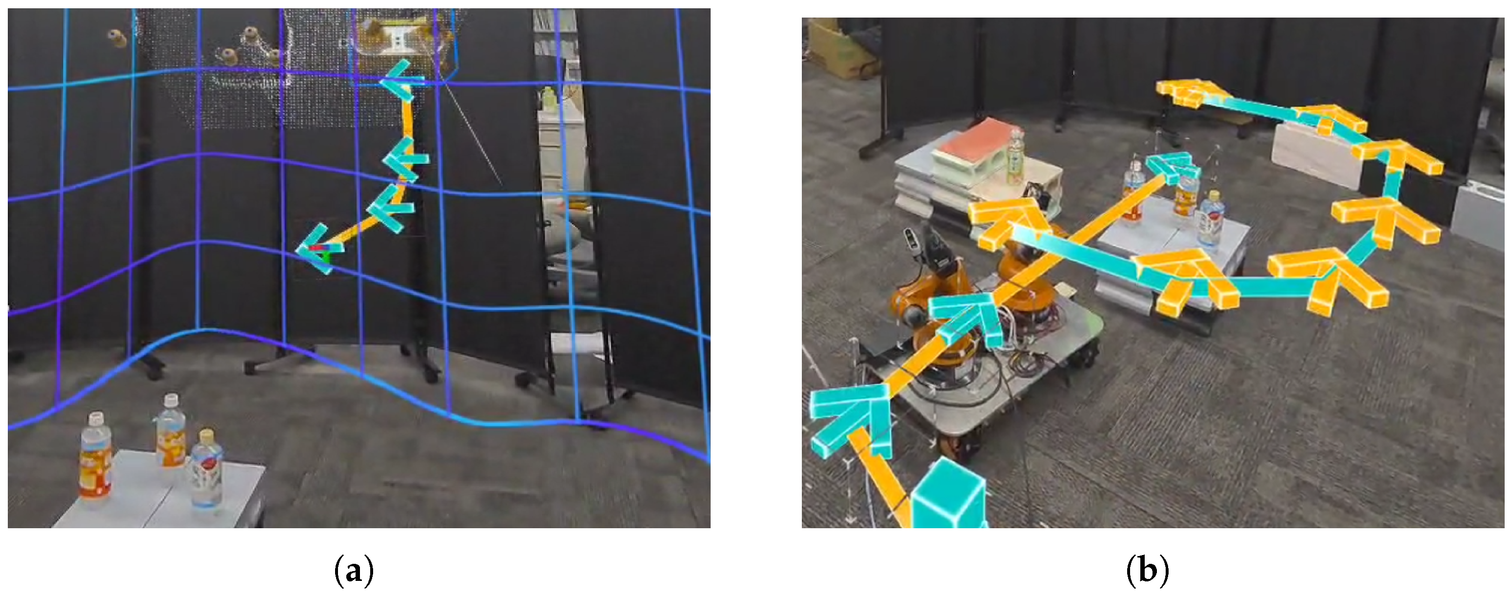
By including Δ ψ ( b ) 2 , the system penalizes excessive base rotation, promoting smoother transitions. The updated waypoint sequence Γ ( b ) is immediately recalculated and redrawn in the MR space, providing real-time visual feedback (see Figure 7).

3.4.2. Case 2: Unknown Path (User-Initialized with Dynamic Update)

On the other hand, when environmental information is incomplete and autonomous path generation is impossible, the user initially presents the base placement path in the MR space, based on the method of the preceding study IRT-MRO [24]. However, relying solely on the user’s initial input is insufficient if the environment changes or if the user’s view is obstructed.
Therefore, in this study, we apply a dynamic adaptation mechanism. As the robot moves along the user-presented path, the known area expands, and the cost map is updated in real-time. Based on this updated cost map, the system locally and autonomously corrects the path, proposing alternative routes to avoid obstacles or optimize movement. As shown in Figure 8, each waypoint is adjusted to a safe and executable position.
Since these correction results are reflected in the MR space, the user can visually understand how the robot’s autonomy supports the navigation.
Cost Map (OccupancyGrid → Grid with Safety Margin)
We construct a cost map C R H × W from the occupancy grid G { 1 , 0 , 100 } H × W (Unknown = −1, Free = 0, Obstacle = 100). First, the base cost for each cell is given by:
C i j = 100 ( G i j = 100 ) [ impassable ] P unk ( G i j = 1 ) [ weak penalty for unknown ] 0 ( G i j = 0 ) .
Next, inflation is performed near obstacles using Manhattan distance d 1 ( d 1 d avoid ) to set C i j P pen (morphological dilation; adding safety margin). Furthermore, from the robot radius r safe and map resolution h, the cell radius is calculated as r c = r safe / h , and expansion based on the Minkowski sum for the actual machine width is added by setting C i j P pen even in the disk neighborhood of Euclidean distance r c . Here, P pen 1 implies “passable but high cost,” naturally encouraging paths away from obstacles.
Path Suggestion (MR Reference → Safety A* Correction)
The reference path designated by the user in the MR space is defined as a sequence of waypoints Γ ¯ = { x ¯ k } k = 0 N , where each x ¯ k R 2 represents a 2D position vector in the map coordinate system. Since the user’s manual input may not account for precise obstacle boundaries or safety margins, the system executes an A* search for each segment ( x ¯ k 1 x ¯ k ) to obtain a collision-free path Π k . The 1-step movement cost l ( i j ) from a cell i to an adjacent cell j, and the heuristic function h ( n ) for a given node n, are formulated as:
l ( i j ) = 1 + { C j = P pen } P pen , h ( n ) = | x n x g | + | y n y g | ,
where { · } denotes the indicator function, C j represents the cost value of the target cell j in the extended cost map, and P pen is a constant penalty cost (set to 50 in this study) assigned to the inflated regions surrounding obstacles. The heuristic h ( n ) utilizes the Manhattan distance between the scalar coordinates of the current node ( x n , y n ) and the goal ( x g , y g ) . Transition to any cell with C j = 100 (occupied) is strictly prohibited.
In the system implementation, two candidate paths are computed for each segment: (a) Π k pen with the penalty cost enabled to prioritize safety clearance, and (b) Π k nop with the penalty disabled to find the geometrically shortest route. The path with the minimum total cost is adopted to construct the finalized trajectory Γ = Π 1 Π 2 Π N , where ⊕ denotes path concatenation. For robot execution, Γ is sampled at fixed spatial intervals δ to generate a waypoint sequence. These points are then transformed into the machine’s local coordinate system using the map base _ link transform obtained from the TF tree and followed under velocity saturation constraints.

3.4.3. Summary of BRI

As described above, the base movement strategy of this study has a two-stage structure applying: (i) “Path proposal based on IRM score and movement cost with user modification” when the path is known, and (ii) “Dynamic path suggestion triggered by user presentation and updated cost maps” when the path is unknown. This enables fulfilling both robot autonomy and user-led interaction, realizing flexible and robust base movement.

3.5. Kinematic Correction Manipulation Module (KCM)

Before presenting the detailed formulation, we summarize the key mechanism of the KCM module. The purpose of KCM is to preserve the operator’s task-level manipulation intent while autonomously resolving robot-side kinematic infeasibility caused by the embodiment gap. To achieve this, KCM combines three elements: pre-grasp interpolation, which smoothly guides the user-generated hand pose toward a robot-feasible grasping pose; null-space optimization, which improves manipulability and joint-limit avoidance without changing the end-effector task; and an FSM-based intervention strategy, which activates assistance only when kinematic risk becomes significant. Thus, the core contribution of KCM is not simple motion smoothing, but online feasibility resolution that maintains intuitive user interaction while ensuring robot-executable motion.
Even when the target is reachable, stable grasp execution is not guaranteed if the user-generated hand motion leads the robot toward a kinematically poor posture. To address this issue, the following formulation combines pre-grasp guidance, null-space-based posture refinement, and FSM-based intervention.

3.5.1. Pregrasp and EE Interpolation

Relying solely on raw user trajectory data may result in instructions that are difficult for the robot to execute. For instance, if a user pinches the top of a bottle, controlling the EE to target the back of the user’s hand might command an inappropriate posture that does not consider graspability.
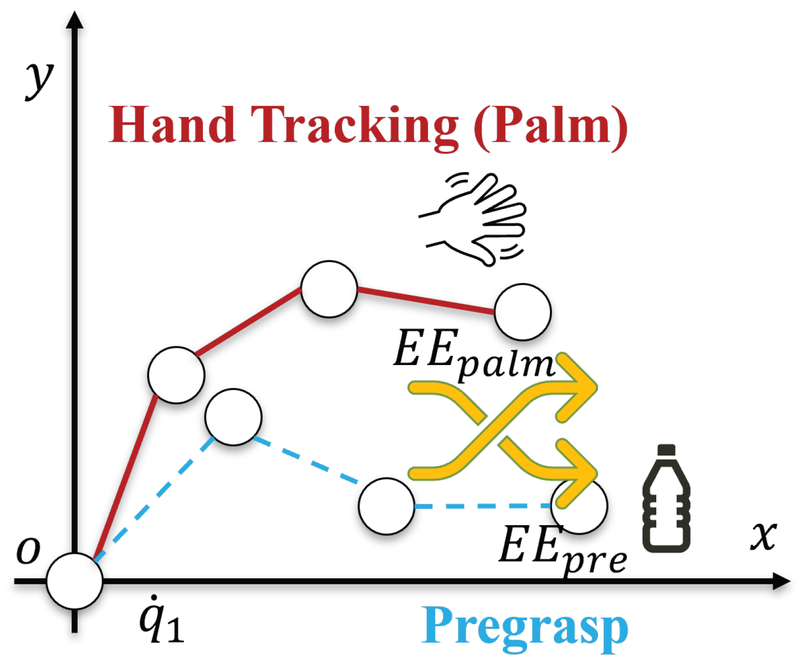
To address this issue, as shown in Figure 9, we generate a stable and executable reference posture (Pregrasp posture x p r e ) for the robot based on the target position p t a r , i ( t ) .
Derivation of Pregrasp Posture
First, for the target’s position p t a r , i ( t ) and orientation (e.g., upright direction for a bottle), we define an offset position p p r e in the approach direction that is easy for the robot hand to access. We solve Inverse Kinematics (IK) targeting this p p r e and the ideal grasping orientation R p r e . From the obtained joint angle solutions, we adopt the one with the highest manipulability as θ p r e and the corresponding end-effector pose as x p r e . This ensures that x p r e is always the “most natural preparation posture for the robot.”
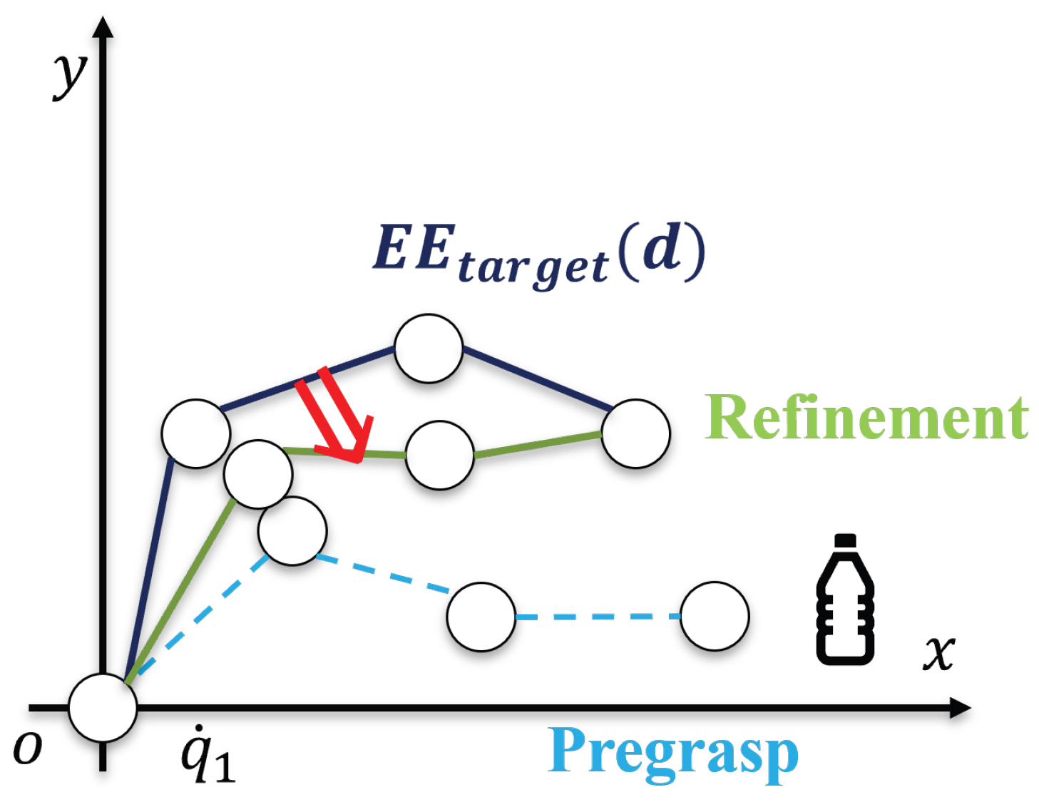
The actual EE target posture is defined by interpolating between the user’s hand-tracking-derived pose E E p a l m and the robot-feasible pre-grasp pose E E p r e ( x p r e ) based on distance:
E E t a r g e t ( d ) = ( 1 β ( d ) ) E E p a l m + β ( d ) E E p r e ,
where β ( d ) [ 0 , 1 ] is an interpolation coefficient based on the distance d to the target.
With this mechanism, the user’s hand tracking data ( E E p a l m ) is strongly reflected when the target is far, and the weight shifts to the stable Pregrasp posture ( E E p r e ) as the robot approaches the target. In other words, user operation is “magnetically” corrected toward the target. Similar to assistive guidance (aim-assist) in video games, this maintains a natural operational feel while ultimately guaranteeing safe and stable grasping for the robot.

3.5.2. Joint Refinement via Null-Space Optimization

In redundant manipulators such as robot arms, multiple joint solutions exist that can realize the same EE position and orientation. The set of degrees of freedom that do not affect the motion of the EE is called the Nullspace [31,32].
Mathematically, for the relationship linking task space velocity x ˙ and joint velocity θ ˙ :
x ˙ = J θ ˙ ,
any θ ˙ n u l l that satisfies J θ ˙ n u l l = 0 belongs to the null space. These motions represent degrees of freedom that can adjust only the joint posture without affecting the EE’s position or orientation.
Utilizing this property, this study optimizes joint posture in parallel with task achievement. The joint velocity is given by:
θ ˙ = J + x ˙ d + P θ H ( θ ) ,
where J + is the Damped Least Squares (DLS) pseudoinverse:
J + = J ( J J + λ I ) 1 ,
and P = I J + J is the null-space projection matrix. The first term guarantees EE tracking, faithfully reproducing the hand motion instructed by the user. The second term is the optimization component projected onto the null space, adjusting the joint posture based on the merit function H ( θ ) as shown in Figure 10.
The merit function is defined as:
H ( θ ) = w m a n i log det ( J J ) + w l i m i t i = 1 n log m i ( θ ) γ θ θ p r e 2 ,
The role of each term is as follows:
  • w m a n i log det ( J J ) : Maximizes the Yoshikawa manipulability measure [33] to avoid Jacobian singularities and prevent the arm from falling into directions where movement is difficult. Physically, this means maintaining motion redundancy by utilizing joint degrees of freedom, guaranteeing the user a sensation of continuous and smooth operation.
  • w l i m i t i log m i ( θ ) : Increases the joint limit margin m i ( θ ) [34] to prevent joint angles from approaching the ends of their range. This is important for ensuring robot longevity and safety, and simultaneously reduces the discomfort users might feel if motion stops suddenly due to awkward postures.
  • γ θ θ p r e 2 : Maintains consistency with the Pregrasp posture to prevent the robot from deviating considerably from the target-specific requirement due to its own optimization. This term maintains a balance between the user’s operational sensation and the robot’s kinematic stability.

3.5.3. Finite State Machine for Grasp Preparation

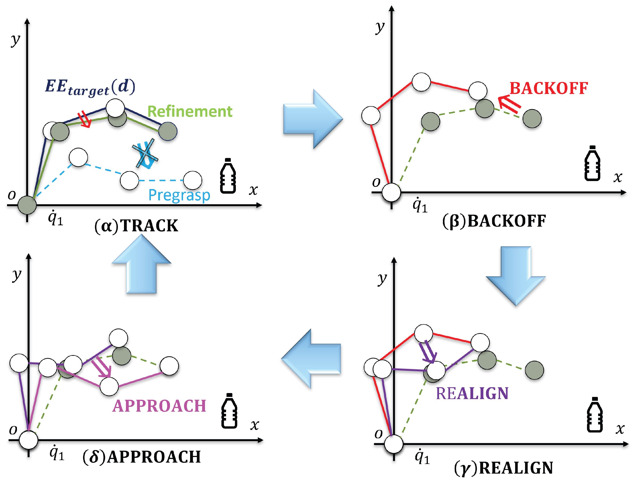
To ensure the entire grasping motion proceeds safely and stably, this study introduces a Finite State Machine (FSM) consisting of four states. An FSM is a classical modeling method that defines system behavior as a combination of “states” and “transitions” [35,36]. The FSM guarantees the compatibility of following the target-level instruction and robot kinematic constraints, preventing failures such as “rushing into the object with an awkward posture.” The state transition diagram is illustrated in Figure 11.
  • TRACK: The stage of tracking the target based on Palm/Pregrasp blending and sequentially updating joint angles via DLS-IK.
  • BACKOFF: If manipulability M ( θ ) or joint margins m i ( θ ) fall below thresholds ( τ m a n i , τ l i m i t ), the robot temporarily retreats to avoid unstable postures.
  • REALIGN: After BACKOFF, joint postures are realigned using null-space optimization until safety conditions are met.
  • APPROACH: When the EE satisfies a stable posture and the distance to the target is d < τ d i s t , the robot executes the final approach for grasping.
As described above, the FSM is a mechanism linking mathematical criteria with user experience. In particular, the transition BACKOFF → REALIGN guarantees that even if the user performs an erroneous operation, the robot autonomously corrects it, realizing “collaborative safety” in HRC.

3.6. Importance of Module Integration

The MASK system proposed in this study consists of three modules: Target Object Identification (TOI), Base Relocation Module based on Inverse Reachability Map (BRI), and Kinematic Correction Manipulation Module (KCM). Each module not only functions independently but also complements the others, thereby overcoming the constraints inherent in conventional MR-based HRC systems.
First, TOI clarifies “which object is to be manipulated” by identifying the intended target with high precision. This target information is input into BRI, which determines whether robot base movement is necessary depending on whether the target is currently graspable. Furthermore, receiving the results from TOI and BRI, KCM compensates for the discrepancies between the human’s intended manipulation goal and the robot’s kinematic constraints, ensuring stable grasping.
In this way, the integration of TOI, BRI, and KCM establishes a continuous processing flow that:
  • Accurately identifies the intended manipulation target,
  • Ensures reachability through appropriate robot base relocation, and
  • Guarantees the stability of the grasping motion.
As a result, the robot moves intuitively and adaptively without relying excessively on the user’s embodiment, providing a stable operational experience for a wide range of users, from novices to experts.
Therefore, the importance of this study lies not merely in individual technical improvements, but in establishing an integrated framework of Target Identification → Reachability Assurance → Stable Grasping for HRC in MR environments.

4. Experiment: Evaluation of KCM

4.1. Experimental Setup

To clarify the superiority of the proposed Kinematic Correction Manipulation Module (KCM), we conducted a comparison with an existing MR-based manipulation framework, “Immersive Robot Teleoperation Based on User Gestures in Mixed Reality Space” (IRT-MRO) [24]. The conventional system focuses on directly transferring user operations in MR space to the robot side and does not sufficiently consider kinematic feasibility or grasping stability.
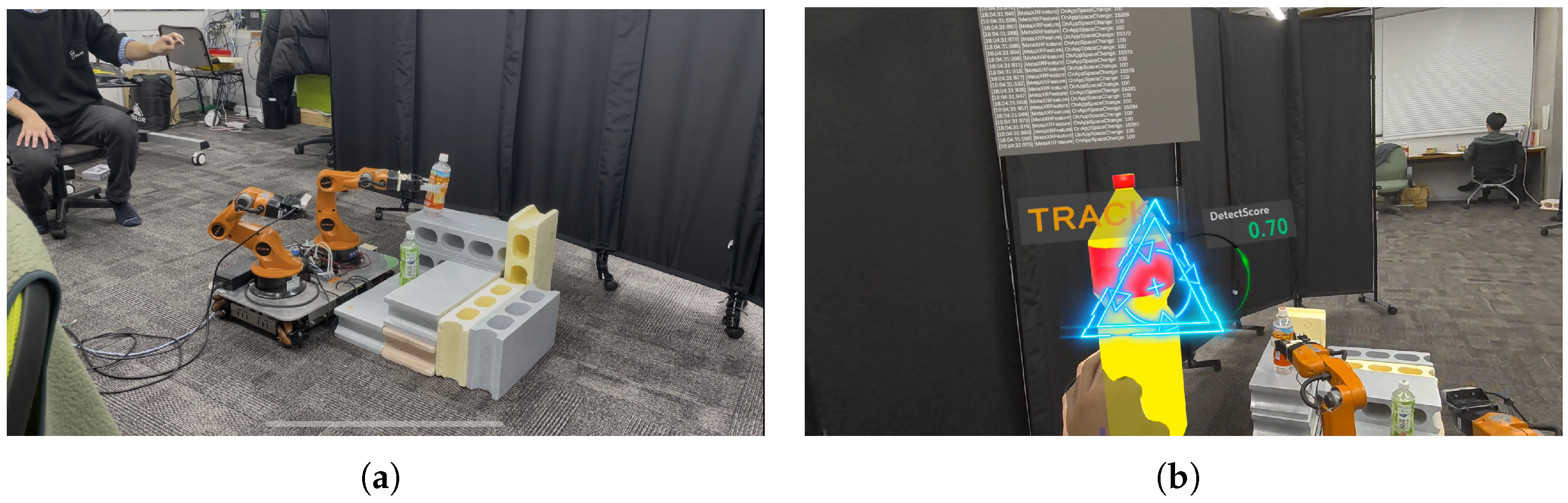
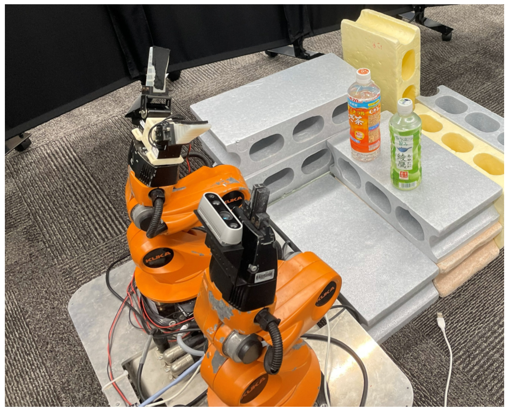
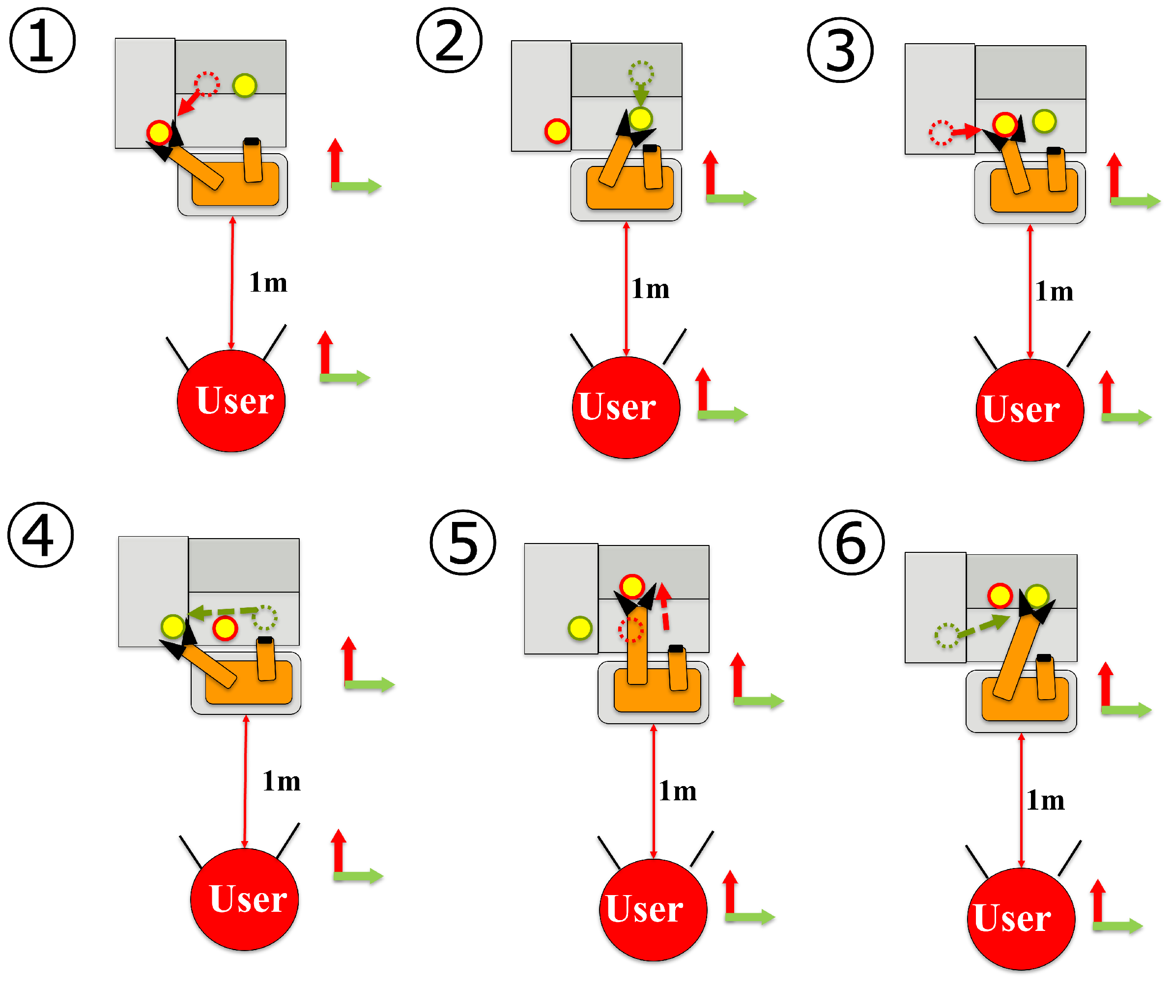
The experimental setup was designed to evaluate both the baseline performance of IRT-MRO and the improvement effects of KCM. Figure 12 shows the task environment for the pick-and-place experiment. A KUKA youBot platform was used, and the user was positioned 1.0 m away from the robot. As the task environment, three-tiered blocks of different heights were installed. The task required the user to swap the placement of two bottles existing within the robot’s reachable range multiple times and finally return them to their original positions.
The specific procedure follows the order 1 to 6 shown in Figure 13. This sequence tests whether stable approaches can be made even to targets at different heights and whether a series of complex operations can be executed accurately. The task is considered successful only if all bottles are correctly returned to their initial positions.
As shown in Figure 14, when the user grasps the MR object, the robot also grasps the actual object. Similarly, when the user releases the MR object, the robot releases the actual object. Through this sequence, the pick-and-place task is executed.
The evaluation metrics were set as follows:
(i)
Workload based on NASA-TLX: Evaluates the subjective operational burden on the user caused by performing the task [37].
(ii)
Grasp Failure Rate: The percentage of trials where the user executed a grasping action (closing the gripper) but failed to grasp the target.
(iii)
Retry Count: The number of times the system’s posture improvement was not completed, requiring the user to perform manual posture readjustment (retry).
(iv)
Convergence to Pregrasp Posture: Evaluates how smoothly user operations were guided to the robot’s recommended posture in the proposed method (described as a characteristic evaluation rather than a comparison).
In addition to the subjective NASA-TLX evaluation, the study included objective operational metrics such as grasp failure rate and retry count to assess behavioral differences in task execution. These metrics were selected because they directly reflect task-level breakdown and recovery behavior during initial use, thereby complementing the subjective workload analysis with observable operational outcomes under each condition. Nevertheless, additional performance measures such as task completion time, motion efficiency, and trajectory smoothness were not systematically analyzed in the present study and should be incorporated in future work to provide a more comprehensive evaluation.
A total of 10 subjects participated in the experiment ( n = 10 ). Verbal informed consent was obtained from all subjects in advance, and this experiment was conducted in accordance with the guidelines of the affiliated institution.
The present experiment should be interpreted as an initial feasibility evaluation of the proposed framework rather than as a comprehensive benchmark for all teleoperation scenarios. The task was intentionally designed as a controlled pick-and-place experiment so that the effects of target identification, reachability-aware base positioning, and kinematic correction could be examined in a consistent manner. At the same time, the task difficulty was increased compared with simpler prior settings: the bottles were arranged on a three-tier platform with upper, middle, and lower levels, and the participants were required to perform repeated sequential pick-and-place operations. Unlike conventional settings with objects placed at a uniform height, this configuration introduced additional reachability and posture-adjustment challenges, particularly for upper and lower targets. Therefore, although the task was controlled, it was not limited to a trivial single-height manipulation scenario. However, more complex situations involving cluttered environments, longer task sequences, and broader multi-object manipulation remain important subjects for future evaluation.
The participant size was determined as an initial exploratory within-subject study aimed at examining the immediate usability and feasibility of the proposed framework for first-time users. Although a larger sample would be desirable for stronger statistical generalization, the present study was intended as a controlled preliminary evaluation to identify whether the proposed assistance mechanism provides measurable benefits at the initial-use stage. Therefore, the current results should be interpreted as preliminary evidence rather than as definitive population-level validation.
Each subject performed the task under both the baseline system (IRT-MRO) condition and the proposed system (KCM) condition. To avoid bias due to order effects, the order of conditions was counterbalanced among subjects.
For statistical analysis, paired comparisons between the baseline and proposed conditions were conducted using the Wilcoxon signed-rank test, with a significance level of α = 0.05 . In addition to p-values, effect sizes were reported using the rank-biserial correlation. Because the study was designed as a small-sample within-subject exploratory evaluation, the analysis focused primarily on paired nonparametric comparison.
The core objective of the MASK system is to enable immediate teleoperation without prior training, allowing even first-time users to handle the robot intuitively. Therefore, we deliberately omitted practice sessions and designated the participants’ first-try (the first trial) as the subject of evaluation. By analyzing the results of these initial attempts, we examined the immediate and intuitive operability of the MASK framework.
While this design was chosen to evaluate first-use usability, we acknowledge that the lack of practice may also introduce a confounding factor related to participants’ unfamiliarity with the MR interface. Accordingly, the present results should be interpreted as an evaluation of immediate usability rather than long-term learned performance.
Throughout the experiment, a total of 120 pick-and-place cycles were performed across all conditions and subjects, amounting to 240 discrete robotic actions (pick or place). This dataset provides a sufficient basis for evaluating the system’s ability to resolve kinematic constraints in real-time during a continuous task sequence.
In this study, all thresholds and weights were fixed as follows:
β ( d ) = hyst - sigmoid ( d ; d in = 0.18 m , d out = 0.22 m , k = 40 , α = 0.2 ) ,
where DLS damping was set to λ = 10 2 (adaptively varying around e + 0.002 in implementation). FSM thresholds were set to: minimum manipulability τ mani = 0.03 , condition number τ cond = 60 , and minimum joint margin τ limit = 0.08 rad . The backoff distance was 0.07 m , the REALIGN timeout was 0.6 s , and the null-space update step was k null = 0.02 . The weights for the merit function were w mani = 1.0 and w limit = 0.3 , with an additional weak pull-back term to the Pregrasp. These values were fixed across all subjects and trials.

Rationale for Embedded Evaluation of TOI (Validation of Subjective Consistency)

The purpose of this study is to realize a system that allows the user to operate intuitively without relying on proficiency, even without detailed knowledge of the robot’s motion characteristics. From this perspective, the evaluation of Target Object Identification (TOI) prioritizes “subjective consistency” how well it matches the user’s internal target selection over quantitative metrics such as physical accuracy rates.
For instance, if a user changes their target during operation and the system switches the identification accordingly, this behavior is “correct,” but a simple stability metric might classify it as an “error.” Conversely, even if the system misinterprets the intended target, if the user compromises to match the robot, the apparent task success rate might improve. To avoid such “numerical traps” and verify whether the system can identify the intended target truly “without imposing a burden on the human, ” this experiment adopts evaluation based on subjective indicators.
Specifically, we assume that the estimation accuracy and tracking performance of TOI are directly reflected in the user’s mental state (NASA-TLX). If TOI estimation is unstable or diverges from intended target, the user is forced to exert high Mental Demand to correct the robot’s erroneous movements, increasing Frustration. Therefore, a reduction in NASA-TLX scores serves as evidence that TOI was able to identify the user’s dynamic target correctly and without discomfort.

4.2. Experimental Results

4.2.1. Subjective Workload Based on NASA-TLX

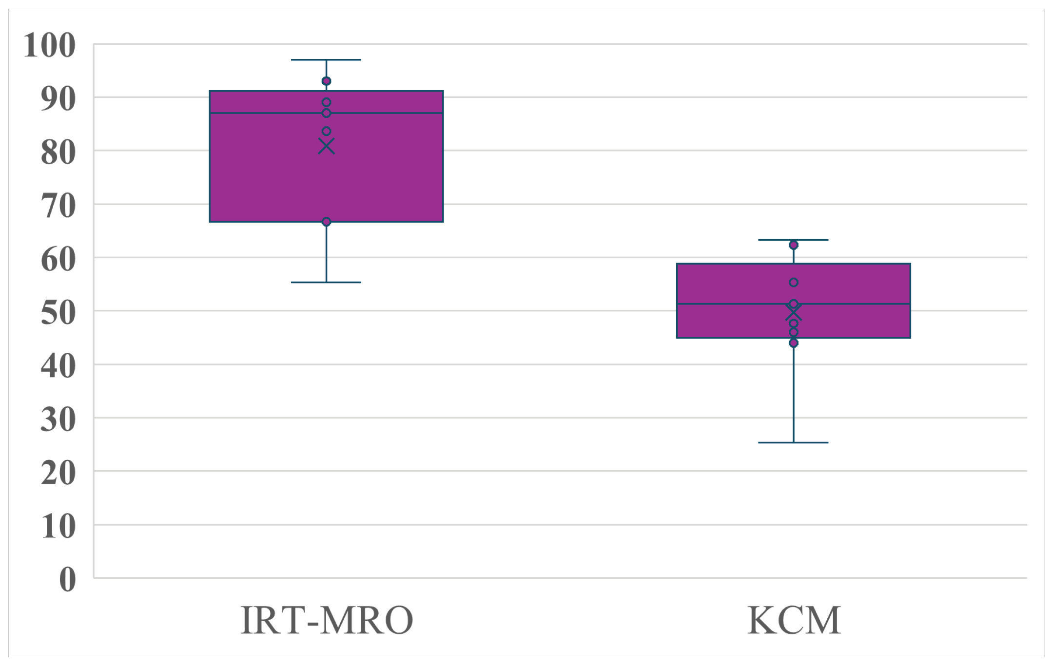
As shown in the experimental results, the NASA-TLX weighted rating (WWL) was substantially improved from 78.78 in the baseline (IRT-MRO) to 50.48 in the proposed KCM. A Wilcoxon signed-rank test revealed that this reduction in workload was statistically significant ( W = 0 , p < 0.01 ), with a large effect size (rank-biserial correlation = 1.00 ). This result reflects the fact that all paired NASA-TLX scores were lower in the proposed condition than in the baseline condition.
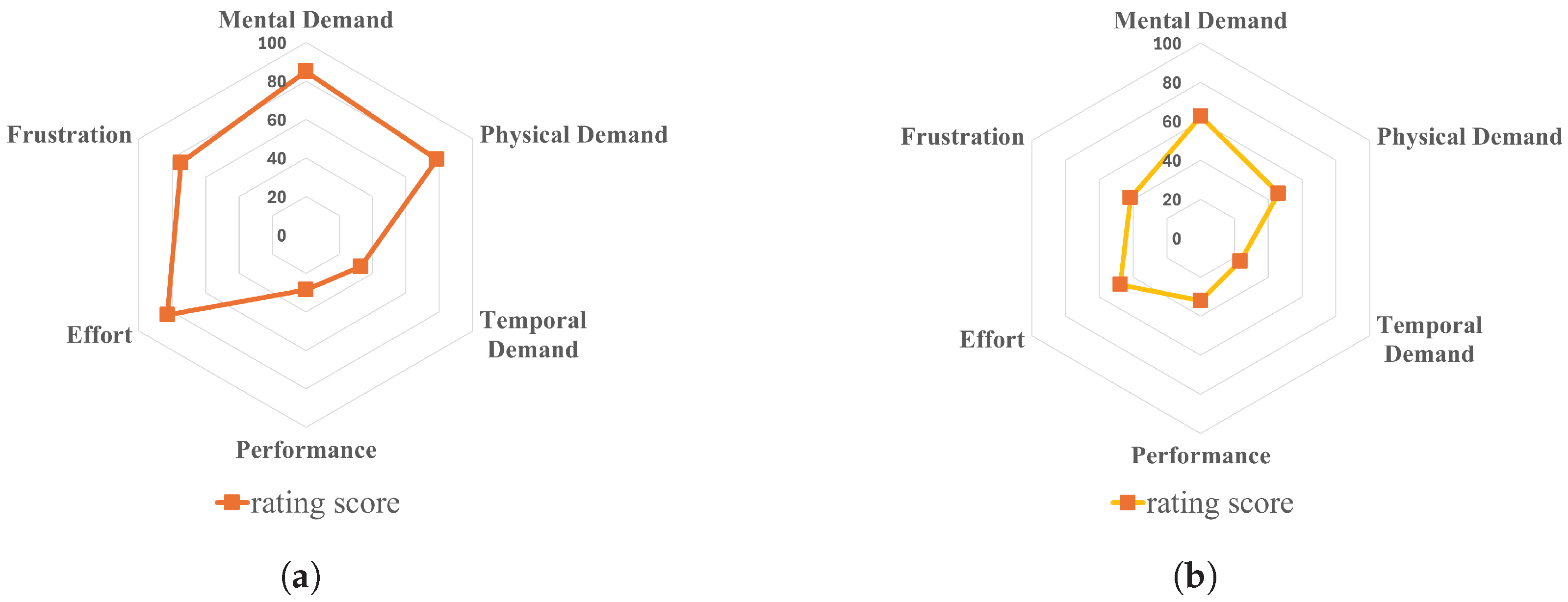
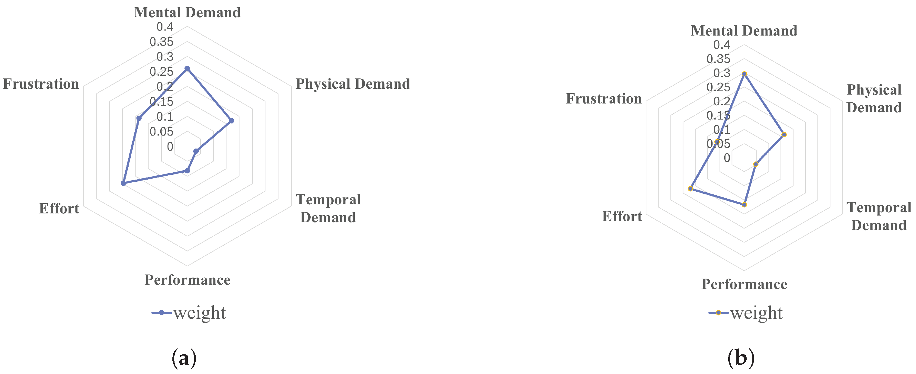
This result confirms that the KCM module effectively mitigates the cognitive and physical burden on the operator. Figure 15 and the radar charts in Figure 16 and Figure 17 visualize this improvement across all dimensions.
  • Physical Demand (PD) & Effort: The rating for PD decreased from 78.5 to 46.2, and Effort decreased from 83.0 to 47.5. This demonstrates that KCM’s autonomous posture correction effectively eliminated the need for unnatural body movements to compensate for robot constraints.
  • Mental Demand (MD) and Cognitive Reallocation: While the raw MD rating markedly decreased from 85.0 to 62.5, the weighted score remained nearly constant (22.4 for IRT vs. 18.7 for KCM). This phenomenon is attributed to the structural weighting of NASA-TLX; as the physical burden (PD and Effort) was drastically mitigated by the system, the relative importance of mental judgment in the task score increased. This suggests a shift in the quality of struggle: as physical stress was mitigated, cognitive resources were reallocated from low-level motion control to high-level task judgment. In other words, the user was freed from the “how to move” struggle and could focus on the “what to do” aspect of the task.
  • Performance & Frustration: Frustration levels substantially improved from 75.0 to 41.5, confirming that the stress caused by kinematic “lock-ups” was effectively suppressed. Self-evaluated performance shifted from 28.5 to 32.0, likely reflecting a reduced sense of manual agency or achievement due to the high degree of system assistance.

4.2.2. Quantitative Operational Performance

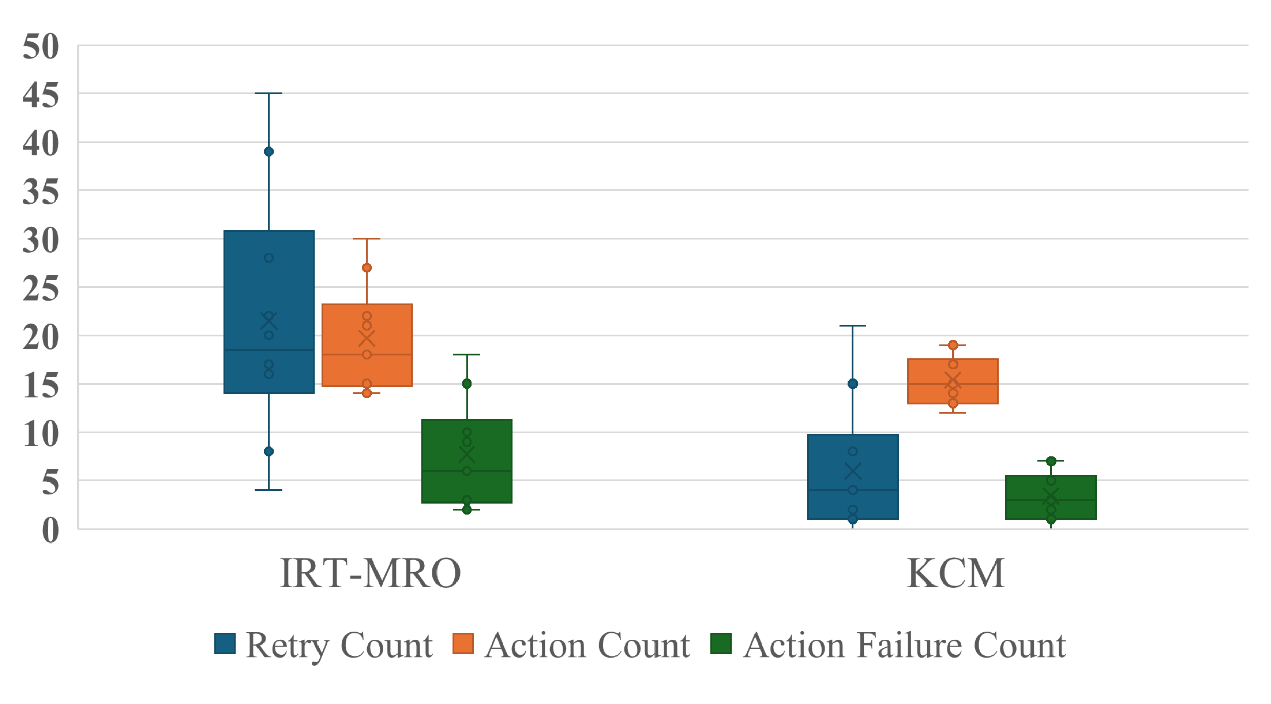
The superiority of KCM was further examined through objective operational metrics across all subjects, as shown in Figure 18.
Figure 18 shows the distributions of Retry Count, Action Count, and Action Failure Count obtained from video-based post hoc annotation of the experimental trials. In addition to these recorded counts, the pick-and-place failure rate was calculated from the ratio between Action Failure Count and Action Count for each participant and condition. The retry count was significantly lower with the proposed method than with IRT-MRO ( W = 0 , p < 0.01 ), with a large effect size (rank-biserial correlation = 1.00 ). Furthermore, the pick-and-place failure rate calculated from the recorded action counts was also significantly lower under the proposed method ( W = 0 , p < 0.01 ), with a large effect size (rank-biserial correlation = 1.00 ). These statistical results indicate that the proposed method reduced both the frequency of recovery actions and the rate of failed pick-and-place operations during task execution.
  • Retry Count for Posture Adjustment: The average number of manual posture readjustments required by the user decreased from 21.5 times to 6.3 times, with a median reduction from 18.7 to 4.0. This drastic reduction confirms that the system successfully resolved kinematic constraints autonomously.
  • Task Efficiency and Stability: The pick-and-place failure rate improved from 35.2% to 20.2%. Additionally, the median action count required to complete the task decreased from 18 to 15. These results demonstrate that KCM not only makes operation easier but also more efficient and accurate, even for first-time users.

4.2.3. Analysis of Kinematic Control Behavior

To verify the internal mechanism of the KCM, we analyzed the transition of the merit function H ( θ ) defined in Equation (26).
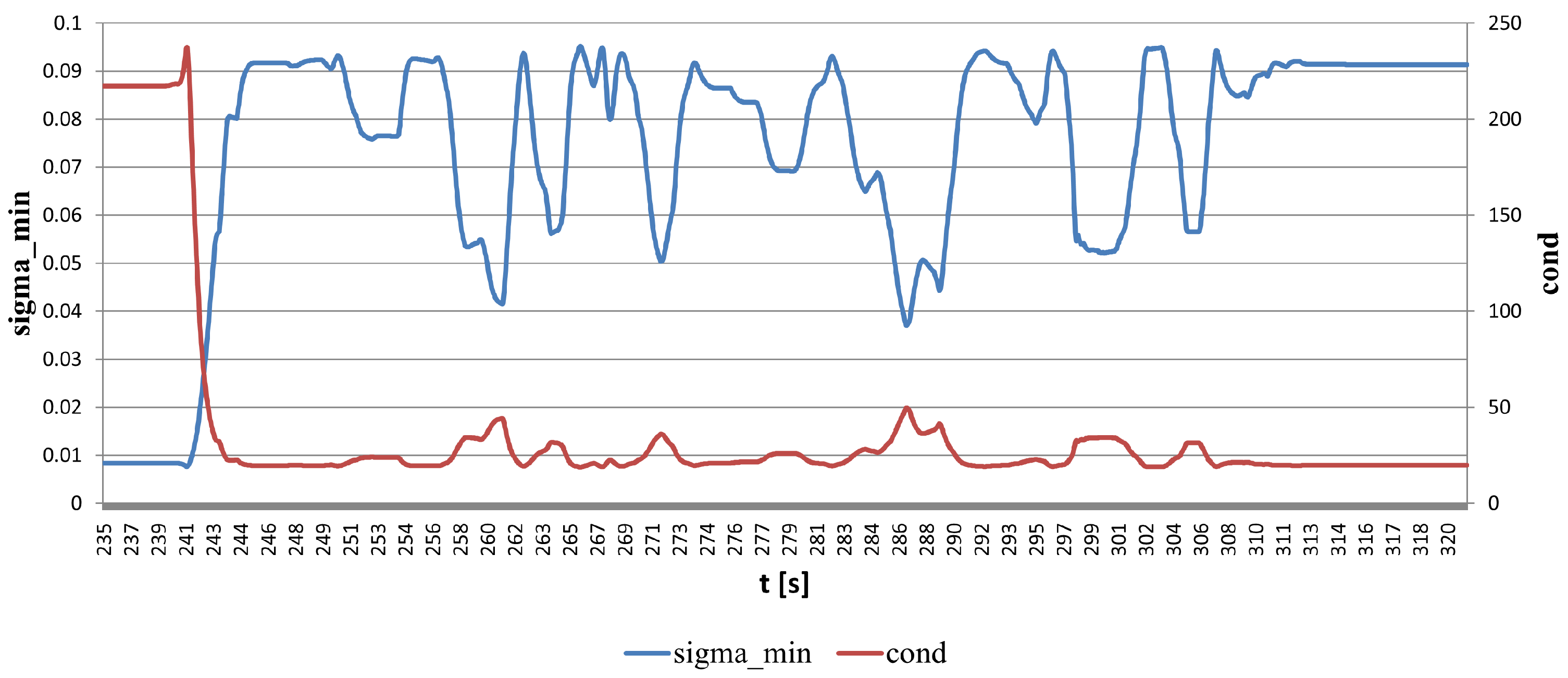
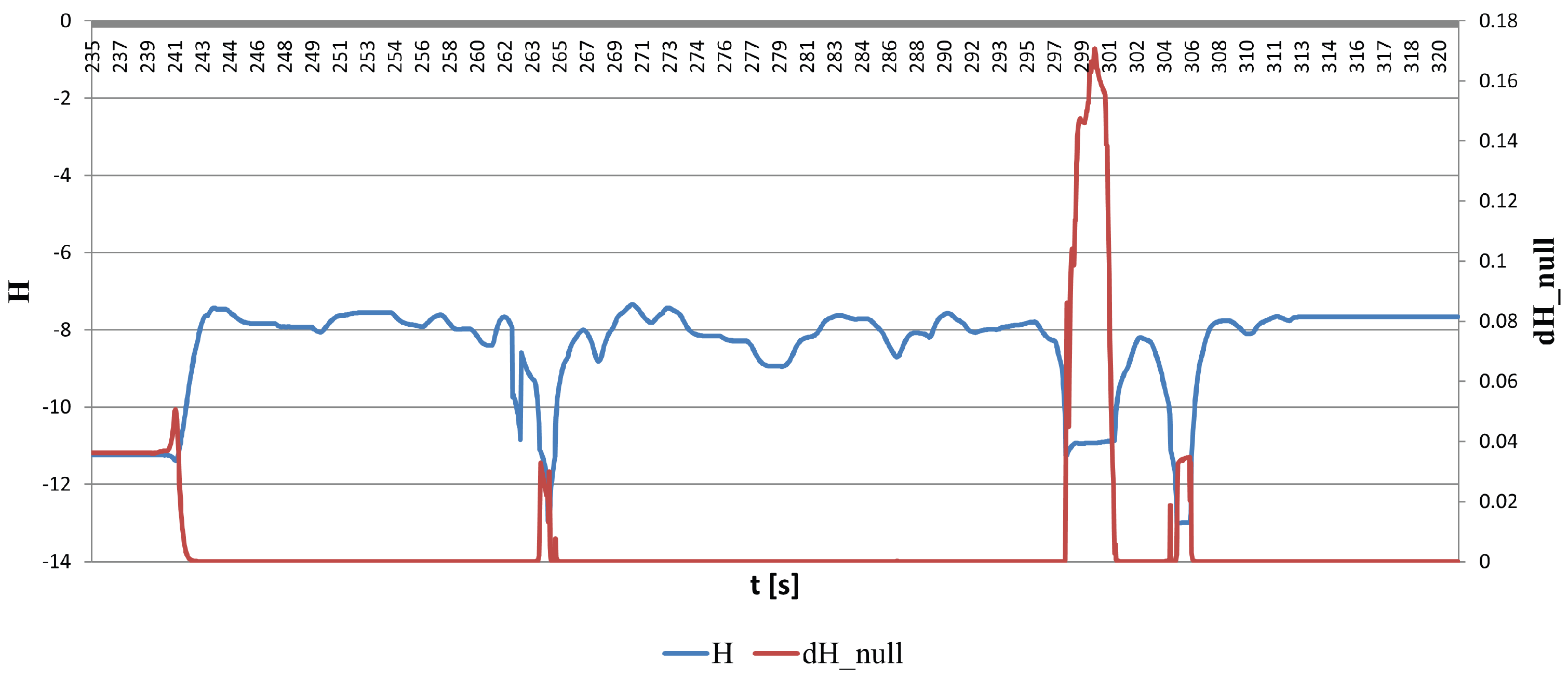
  • Singularity Avoidance and Recovery: As shown in Figure 19, at t 241  s, the condition number c o n d spiked above 200, but KCM intervention immediately restored it to a stable range below 50, preventing the operational “freeze” observed in the baseline.
  • Reactive Posture Correction via Null-space Optimization: As shown in Figure 20, a clear inverse correlation was observed between the merit function H and the null-space update vector d H n u l l . Sharp spikes in d H n u l l occurred precisely when H began to decrease due to unfavorable kinematics (e.g., t = 241  s, t = 298  s). This reactive behavior, driven by the gradient of the log-terms in H ( θ ) , ensures autonomous posture recovery using redundant degrees of freedom without affecting the target trajectory.
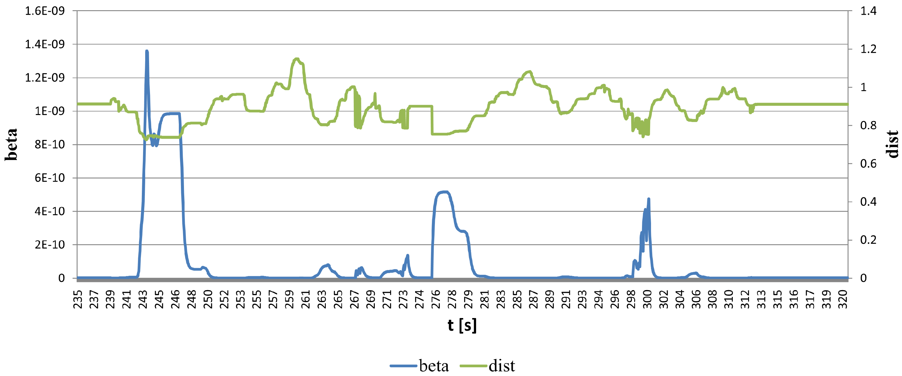
  • Adaptive Intervention Blending: As shown in Figure 21, the blending coefficient β adjusted dynamically based on the distance d i s t and kinematic risk. β provided localized support during critical phases (e.g., t = 243  s, t = 300  s) while maintaining user agency during free movement.

4.3. Discussion

The experimental results demonstrate that KCM effectively conceals the robot’s mechanical constraints, bridging the gap between complex kinematics and intuitive human operation. The reduction in Retry Count and Physical Demand confirms that the system significantly alleviates the need for the user to consciously manage the robot’s state.
The shift in Mental Demand highlights a cognitive reallocation, where users focus on target-level manipulation goals rather than low-level kinematic control. This transition from physical coordination to target-oriented decision-making is further evidenced by the fact that the MD weighted score remained constant despite the substantial reduction in raw rating. Furthermore, the reactive spikes in d H n u l l and the dynamic blending of β show that KCM acts as an adaptive safety net, providing assistance only when necessary. This balance ensures that the MASK framework enables immediate, intuitive teleoperation for novice users without the need for prior training by systematically resolving the embodiment gap through target-based active resolution.
Table 1 compares representative prior teleoperation frameworks with the proposed MASK system. Rather than focusing only on task performance, this comparison emphasizes whether each study explicitly addresses the key methodological components claimed in this work, namely target identification, reachability-aware base relocation, and kinematic correction. Here, Interface type indicates the primary immersive interaction modality used in each study, Target ID indicates whether the system explicitly infers or identifies the intended manipulation target, Reachability/Base relocation indicates whether the framework explicitly supports reachability-aware spatial adaptation or mobile base repositioning, and Kinematic correction indicates whether robot-side kinematic feasibility is actively adjusted during manipulation. The columns Real robot and User study indicate whether the system was validated with a physical robotic platform and whether an experimental user evaluation was reported, respectively.
As summarized in Table 1, prior studies have addressed important but largely separate aspects of immersive teleoperation, such as MR-based visualization, direct manipulation, or limited feasibility support. In contrast, the proposed MASK framework integrates target identification, reachability-aware base relocation, and kinematic correction within a unified MR-based shared-control architecture. This integrated design is intended to reduce dependence on operator proficiency by resolving spatial and kinematic constraints online rather than leaving them to manual adaptation.
A limitation of the present study is the still limited number of participants ( n = 10 ). Although the within-subject design enabled a controlled comparison of initial-use performance between the baseline and proposed systems, broader validation with a larger and more diverse participant pool will still be necessary to strengthen generalizability and to further examine variability across user characteristics and operation styles. These points will be important directions for future work.
To provide a quantitative reference regarding participant size, we additionally conducted a sample-size estimation using G*Power (version 3.1.9.7) [38] under a paired-comparison framework, with Retry Count as the primary endpoint. Under a two-tailed setting ( α = 0.05 , power = 0.80 ) and an effect size of d z = 2.01 estimated from the paired differences in the current dataset, the required sample size was estimated to be N = 5 . Since the present study included 10 participants, the current sample size satisfies this requirement for the selected primary endpoint. Nevertheless, broader validation will still require a larger and more diverse participant pool.
Another practical consideration is system latency, which can significantly affect user experience and control stability in MR teleoperation. In the present study, the robot and the MR device were operated in the same physical space, while ROS-based communication was maintained within the same local network to minimize communication delay during the user study. User experience and perceived operational burden were evaluated through NASA-TLX, which provided an indirect assessment of usability under the tested conditions. However, end-to-end latency itself was not quantitatively measured, and its direct relationship to control stability was not separately analyzed in the present experiment. Therefore, latency remains an important issue for practical deployment, especially in more complex or wide-area teleoperation settings, and should be evaluated more systematically in future work.

5. Preliminary Case Study: Functional Validation of BRI

To verify the functional feasibility of the proposed BRI pipeline, we conducted a preliminary case study focused on the integration of optimal base selection and autonomous navigation. Consistent with the validation protocol established in the preceding study [24], this functional verification was conducted as a single-subject case study. This approach allows us to rigorously monitor the system’s technical response and repeatability during continuous operation, distinguishing the technical validation from the multi-subject user study in Section 4.

5.1. Validation Setup

To verify the effectiveness of the proposed Inverse Reachability Map (IRM) system, we designed a stepwise pick-and-place scenario. In this pilot trial, the system focusing on optimal base selection by IRM was evaluated in a unified scenario.
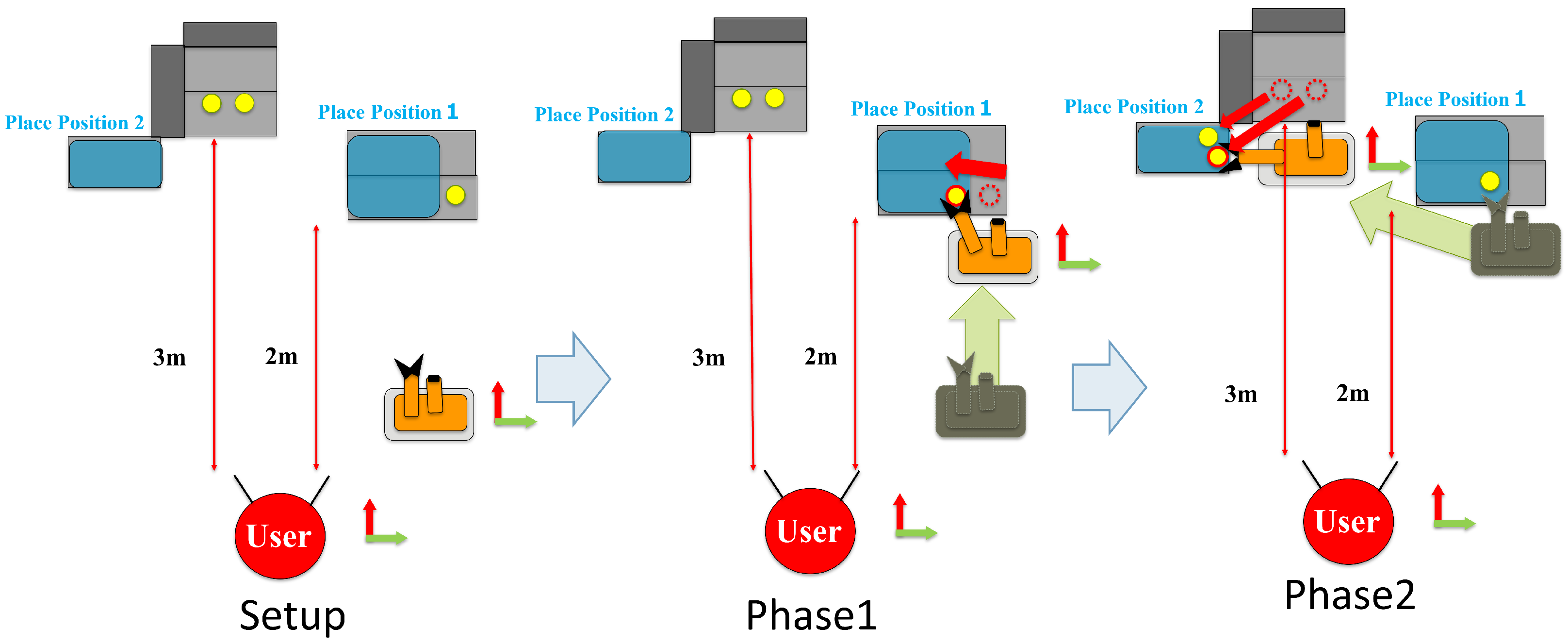
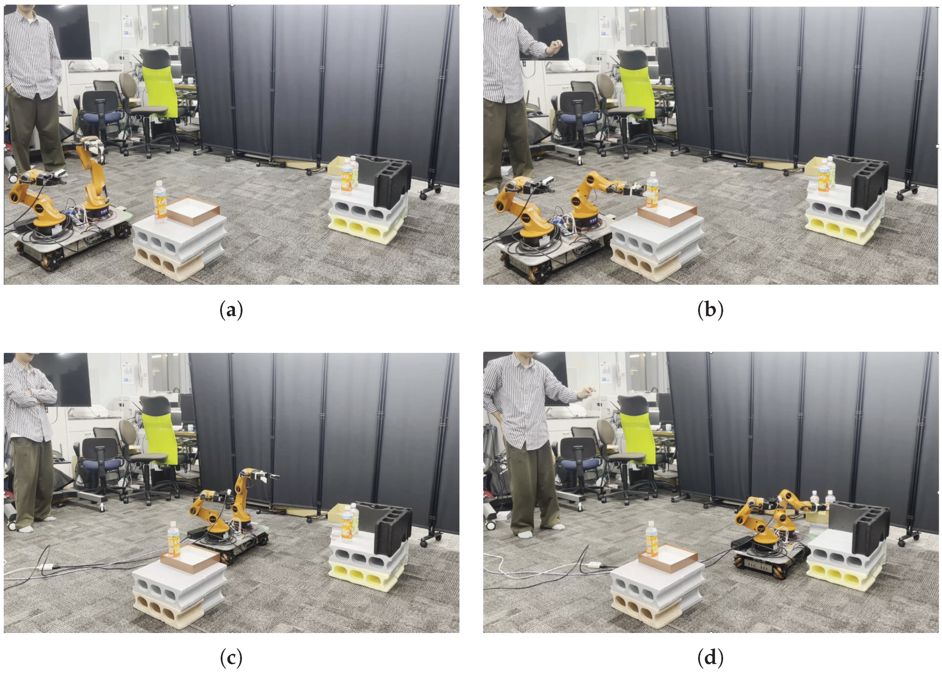
The validation setup utilized the KUKA youBot platform, integrating omnidirectional movement by the mobile base and the 6-DOF manipulator. PET bottles were used as target objects and placed at positions that were impossible to grasp directly from the robot’s initial position. The user stood approximately 1.0 m away from the robot to operate the task via the MR device. The specific task execution sequence is illustrated in Figure 22, while the visual feedback provided to the user and the actual experimental environment are shown in Figure 23 and Figure 24, respectively.
The functional validation was conducted in two phases. Phase 1: The user was required to move the base position once based on BRI, and then pick and place a single bottle. The purpose was to confirm whether the robot could move to a position where grasping is actually possible, following the optimal solution considering the IRM score and movement cost. Phase 2: After performing another base movement, the user performed a task of picking and placing two bottles continuously. This phase verified whether BRI could continuously stabilize the task through multiple relocations. This task sequence was repeated 10 times. In total, the evaluation encompasses 20 autonomous base relocations (10 for Phase 1 and 10 for Phase 2) and 60 discrete manipulation actions (30 picks and 30 places). This high-density operation set allows for a rigorous assessment of the system’s repeatability and the impact of cumulative errors, such as localization drift, over an extended operational period.
Base Relocation Success (BRS) is defined as the robot’s ability to reach the IRM-optimized destination for the primary target object, ensuring it is within the physical reachable workspace. In Phase 2, although two bottles are present, the relocation is optimized only for the first bottle (primary target). The second bottle is treated as a test of the “reachability margin” from the same base position.
The evaluation metrics were: (i) the Base Relocation success rate, evaluating the BRI’s navigation to the primary target; (ii) the Manipulation success rate, calculated for 60 discrete actions (30 picks and 30 places); and (iii) the overall task success rate per phase. Through these settings, we aimed to clarify BRI’s ability to autonomously and efficiently relocate the robot base and improve task success rate and stability in task expansion from single to multiple targets. The single-subject setting in this case study was adopted as a pilot evaluation to verify the feasibility and reproducibility of the BRI pipeline, adhering to the experimental design of the baseline framework [24].

5.2. Results

The preliminary results for the BRI pipeline are summarized in Table 2. These figures serve as a technical baseline to evaluate the logic of the IRM-based relocation and its robustness against environmental factors within a unified scenario.
In Phase 1 (single pick-and-place), the system achieved a high success rate of 90.0% for both relocation and manipulation. The robot successfully navigated to the IRM-optimized base positions, confirming the basic feasibility of the proposed method for single-target scenarios.
In Phase 2 (dual pick-and-place), the relocation success rate for the primary target decreased to 70.0%, and the manipulation success rate dropped to 65.0%. This decrease was primarily attributed to the structural limitation of the current BRI algorithm, which optimizes the base position solely for the primary target without computing the intersection of reachable regions for subsequent targets. Consequently, secondary targets often fell near the boundary of the workspace, making the system highly sensitive to the accompanying localization drift. Overall, the integrated system achieved an 73.3% success rate for manipulation, successfully executing 44 out of 60 discrete actions.

5.3. Discussion

The findings from this case study, derived from a cumulative total of 80 system operations (20 movements and 60 manipulations), demonstrate that the IRM-based system is generally effective for autonomous relocation. However, the results also reveal the system’s limitation in multi-step planning. The 80.0% success rate in base relocation indicates the reliability of the BRI algorithm’s logic for single targets, while the 73.3% success rate in manipulation highlights the challenges of handling multi-target constraints and maintaining visual consistency in MR-based HRI.

5.3.1. Impact of Localization Drift on Visualization

The primary cause of failure was the localization drift in the LiDAR-based SLAM system. The MR origin was updated based on the variation of the base_link relative to the map frame. Due to factors such as wheel slippage and measurement noise, the robot’s perceived position in the map frame occasionally drifted from its actual physical location.
This drift led to inaccurate visualization in the MR interface. While the BRI algorithm internally calculated a path based on the robot’s drifted coordinates (often leading to a “logical” success but a “physical” failure), the virtual representation (the “Digital Twin”) appeared misaligned to the user. This gap between the real world and the MR overlay directly impacted the success of fine manipulation tasks.
It should be noted that while the current MASK framework is inherently adaptive to kinematic inconsistencies, closed-loop compensation for sensor-derived disturbances, such as SLAM-based localization drift, remains a subject for future research. Specifically, the discrepancy between the physical robot and its “Digital Twin” in the MR space directly affects the reliability of the BRI module. To address this in practical applications, it is essential to implement an external ground-truth correction mechanism. Potential solutions include:
  • External Tracking Systems: Integrating high-precision trackers (e.g., HTC Vive Trackers or OptiTrack) on the robot base to continuously correct the odometry drift in the MR coordinate system.
  • Visual Marker Compensation: Placing fiducial markers (e.g., AprilTags or QR codes) at key locations in the environment. The robot can scan these markers to periodically relocalize and reset the accumulation of SLAM errors.
Implementing these “anchor” mechanisms would ensure that the spatial optimization calculated by BRI is faithfully executed in the physical world.

5.3.2. Multi-Target Optimization Constraints and Error Accumulation

Phase 2 was explicitly designed as a stress test to evaluate the system’s robustness under continuous operation and to identify the boundary conditions of the current single-target optimization logic. The decline in performance during this phase highlighted a critical limitation in the current path planning pipeline. The failures were driven by two interacting factors:
  • Single-Target Optimization Bias (Primary Factor): The current BRI module generates the optimal base position b * based solely on the Inverse Reachability Map (IRM) of the first target. It does not currently calculate the intersection of reachable regions for multiple targets (i.e., IRM ( t 1 ) IRM ( t 2 ) ). Consequently, while the base position was optimal for the first grasp, the second target often resided near the extreme edge of the robot’s reachable workspace. This lack of multi-objective optimization significantly reduced the margin for error.
  • Error Accumulation: The extended operation time and sequential movements in Phase 2 led to a higher accumulation of localization drift compared to Phase 1. When combined with the narrow workspace margin mentioned above, even minor localization errors were sufficient to render the second target physically unreachable.
Under these conditions, visual misalignment often led users to believe the grasp would fail, prompting manual corrections via the MR interface. However, since the system’s internal logic was consistent with its own perceived (but drifted) coordinates, these manual adjustments sometimes moved the robot to positions where the second target became kinematically inaccessible. These findings confirm that future iterations of the MASK framework must incorporate multi-target IRM intersection to ensure robust base placement for sequential manipulation tasks.
Limitations and Future Work
While the MASK framework demonstrates substantial improvements in usability, this study has several limitations. First, the evaluation of the KCM module was conducted with a limited sample size ( n = 10 ). Although statistical significance regarding workload reduction was confirmed, further large-scale trials with a broader demographic are recommended to validate the generalizability of these findings.

6. Conclusions

This study proposed the Mixed Reality Adaptive Spatial and Kinematic Support (MASK) framework as an adaptive shared-control solution to the “Embodiment Gap” in Mixed Reality (MR)-based teleoperation. In this study, the Embodiment Gap was addressed not merely as a motion-mapping mismatch, but as a shared-control problem in which human task intent and robot-side spatial and kinematic feasibility must be resolved jointly.
By integrating target identification based on body motion features (TOI), spatial optimization via Inverse Reachability Maps (BRI), and kinematic correction (KCM), the system dynamically harmonizes the human’s intended manipulation goal with the robot’s physical constraints. Our findings demonstrate that this adaptive approach not only yields a statistically significant reduction in perceived workload ( p < 0.05 ) but also facilitates a qualitative “Cognitive Reallocation,” enabling operators to focus their attention on target-level manipulation goals rather than low-level motor coordination.
The results highlight that within the context of Cyber-Physical Systems (CPS), the subjective reliability of the visual interface is as critical as the computational accuracy of the underlying algorithms. The preliminary case study on the BRI pipeline revealed that sensor-derived disturbances, such as SLAM-based localization drift, pose a substantial challenge to maintaining the alignment of the digital twin. Furthermore, the stress test on continuous operation identified the structural limitations of single-target optimization, underscoring the necessity of calculating multi-target reachable intersections for robust sequential tasks. This identification of the gap between logical consistency and physical reality provides crucial insights for the refinement of human-centered adaptive systems.
The successful integration of TOI, BRI, and KCM demonstrates that bridging the Embodiment Gap requires a multi-layered approach that addresses both spatial and kinematic levels simultaneously. By providing a transparent representation of the identified target and planned actions, the MASK framework effectively mitigates the “Gulf of Execution” and the “Gulf of Evaluation” that typically hinder intuitive teleoperation. This holistic integration suggests that effective Human–Robot Collaboration is achieved through a symbiotic relationship where the robot’s physical configuration and kinematics are dynamically adjusted to match the intended target, rather than forcing the human operator to adapt to the machine’s mechanical constraints. Taken together, these results suggest that the proposed framework can mitigate the Embodiment Gap at the stages of target selection, reachability-aware base positioning, and grasp execution, although the extent of this mitigation was examined only in a limited experimental setting. The present findings should, therefore, be interpreted as an initial validation, since the evaluation was conducted with a small number of participants and a relatively simple pick-and-place task.
Future work will prioritize two key technical advancements: (1) implementing external spatial anchoring mechanisms (e.g., visual markers or trackers) to ensure digital twin consistency against SLAM drift, and (2) extending the BRI algorithm to support multi-objective optimization for continuous manipulation. Additionally, we intend to conduct larger-scale user studies to further validate the framework’s generalizability across broader demographics and practical scenarios.

Author Contributions

Conceptualization, S.O. and K.S.; methodology, S.O.; software, S.O.; validation, S.O. and K.S.; formal analysis, S.O. and K.S.; investigation, S.O.; writing—original draft preparation, S.O. and K.S.; writing—review and editing, S.O. and K.S.; visualization, S.O.; supervision, K.S. All authors have read and agreed to the published version of the manuscript.

Funding

This research received no external funding.

Institutional Review Board Statement

According to institutional practice, ethical review and approval were not required for this study because it involved a preliminary non-clinical MR teleoperation experiment with voluntary adult participants and did not include physical human–robot contact, biometric measurement, collection of private personal information, sensory stimulation, or vulnerable participants.

Informed Consent Statement

Verbal informed consent to participate in the study was obtained from all subjects involved. Before the experiment, all participants were informed of the purpose and procedure of the study, the voluntary nature of participation, possible risks, data handling, and their right to withdraw at any time without disadvantage.

Data Availability Statement

The data presented in this study are available on request from the corresponding author.

Conflicts of Interest

The authors declare no conflicts of interest.

Abbreviations

The following abbreviations are used in this manuscript:
HRCHuman–Robot Collaboration
MRMixed Reality
MASKMixed reality Adaptive Spatial and Kinematic support
TOITarget Object Identification module
IRMInverse Reachability Map
BRIBase Relocation Module based on Inverse Reachability Map
KCMKinematic Correction Manipulation module

References

  1. Ajoudani, A.; Zanchettin, A.M.; Ivaldi, S.; Albu-Schäffer, A.; Kosuge, K.; Khatib, O. Progress and prospects of the human–robot collaboration. Auton. Robot. 2018, 42, 957–975. [Google Scholar] [CrossRef] [Scilit]
  2. Matheson, E.; Minto, R.; Zampieri, E.G.G.; Faccio, M.; Rosati, G. Human–Robot Collaboration in Manufacturing Applications: A Review. Robotics 2019, 8, 100. [Google Scholar] [CrossRef] [Scilit]
  3. Sheridan, T.B. Human-Robot Interaction: Status and Challenges. Hum. Factors 2016, 58, 525–532. [Google Scholar] [CrossRef] [Scilit] [PubMed]
  4. Villani, V.; Pini, F.; Leali, F.; Secchi, C. Survey on human-robot collaboration in industrial settings: Safety, intuitive interfaces and applications. Mechatronics 2018, 55, 248–266. [Google Scholar] [CrossRef] [Scilit]
  5. Krüger, J.; Lien, T.K.; Verl, A. Cooperation of human and machines in assembly lines. CIRP Ann. 2009, 58, 628–646. [Google Scholar] [CrossRef] [Scilit]
  6. Dragan, A.D.; Lee, K.C.T.; Srinivasa, S.S. Legibility and predictability of robot motion. In Proceedings of the 2013 8th ACM/IEEE International Conference on Human-Robot Interaction (HRI), Tokyo, Japan, 3–6 March 2013; pp. 301–308. [Google Scholar] [CrossRef] [Scilit]
  7. Nikolaidis, S.; Hsu, D.; Srinivasa, S. Human-robot mutual adaptation in collaborative tasks: Models and experiments. Int. J. Robot. Res. 2017, 36, 618–634. [Google Scholar] [CrossRef] [Scilit]
  8. Norman, D.A. The Psychology of Everyday Things; Basic Books: New York, NY, USA, 1988. [Google Scholar] [CrossRef] [Scilit]
  9. Delmerico, J.; Mueggler, E.; Nitsche, J.; Scaramuzza, D. Spatial Computing and Intuitive Interaction: Bringing Mixed Reality and Robotics Together. IEEE Robot. Autom. Mag. 2022, 29, 45–57. [Google Scholar] [CrossRef] [Scilit]
  10. Su, Y.-P.; Chen, X.-Q.; Zhou, T.; Pretty, C.; Chase, G. Mixed-Reality-Enhanced Human–Robot Interaction with an Imitation-Based Mapping Approach for Intuitive Teleoperation of a Robotic Arm-Hand System. Appl. Sci. 2022, 12, 4740. [Google Scholar] [CrossRef] [Scilit]
  11. Ens, B.; Lanir, J.; Tang, A.; Bateman, S.; Lee, G.; Piumsomboon, T.; Billinghurst, M. Revisiting Collaboration through Mixed Reality: The Evolution of Groupware. Int. J. Hum. Comput. Stud. 2019, 131, 81–98. [Google Scholar] [CrossRef] [Scilit]
  12. de Belen, R.A.J.; Nguyen, H.; Filonik, D.; Del Favero, D.; Bednarz, T. A systematic review of the current state of collaborative mixed reality technologies: 2013–2018. AIMS Electron. Electr. Eng. 2019, 3, 181–223. [Google Scholar] [CrossRef] [Scilit]
  13. Milgram, P.; Kishino, F. A Taxonomy of Mixed Reality Visual Displays. IEICE Trans. Inf. Syst. 1994, E77-D, 1321–1329. [Google Scholar]
  14. Chen, J.Y.C.; Haas, E.C.; Barnes, M.J. Human Performance Issues and User Interface Design for Teleoperated Robots. IEEE Trans. Syst. Man Cybern. Part C (Appl. Rev.) 2007, 37, 1231–1245. [Google Scholar] [CrossRef] [Scilit]
  15. Nielsen, C.W.; Goodrich, M.A.; Ricks, R.W. Ecological Interfaces for Improving Mobile Robot Teleoperation. IEEE Trans. Robot. 2007, 23, 927–941. [Google Scholar] [CrossRef] [Scilit]
  16. Si, W.; Wang, N.; Yang, C. A review on manipulation skill acquisition through teleoperation-based learning from demonstration. Cogn. Comput. Syst. 2021, 3, 1–16. [Google Scholar] [CrossRef] [Scilit]
  17. Leidner, D.; Bartels, G.; Bejjani, W.; Albu-Schäffer, A.; Beetz, M. Cognition-enabled robotic wiping: Representation, planning, execution, and interpretation. Robot. Auton. Syst. 2019, 114, 199–216. [Google Scholar] [CrossRef] [Scilit]
  18. Fang, H.C.; Ong, S.K.; Nee, A.Y.C. Novel AR-based interface for human-robot interaction and visualization. Adv. Manuf. 2014, 2, 275–288. [Google Scholar] [CrossRef] [Scilit]
  19. Li, C.; Zheng, P.; Yin, Y.; Pang, Y.M.; Huo, S. An AR-assisted Deep Reinforcement Learning-based approach towards mutual-cognitive safe human-robot interaction. Robot. Comput. Integr. Manuf. 2023, 80, 102471. [Google Scholar] [CrossRef] [Scilit]
  20. Wang, X.; Shen, L.; Lee, L.-H. A Systematic Review of XR-Enabled Remote Human-Robot Interaction Systems. ACM Comput. Surv. 2025, 57, 273. [Google Scholar] [CrossRef] [Scilit]
  21. Xu, F.; You, H.; Zhou, T.; Du, J. Augmented reality robot manipulation with physical mock-up and improved spatial cognition. Int. J. Hum.-Comput. Stud. 2025, 205, 103658. [Google Scholar] [CrossRef] [Scilit]
  22. Yeh, H.-H.; Chang, Y.-W.; Liu, Y.-C. Intuitive hand motion-based teleoperation system for human-mobile manipulator interaction using mixed reality. Control Eng. Pract. 2025, 164, 106467. [Google Scholar] [CrossRef] [Scilit]
  23. Roldán, J.J.; Peña-Tapia, E.; Martín-Barrio, A.; Olivares-Méndez, M.A.; Del Cerro, J.; Barrientos, A. Multi-Robot Interfaces and Operator Situational Awareness: Study of the Impact of Immersion and Prediction. Sensors 2017, 17, 1720. [Google Scholar] [CrossRef] [Scilit]
  24. Esaki, H.; Sekiyama, K. Immersive Robot Teleoperation Based on User Gestures in Mixed Reality Space. Sensors 2024, 24, 5073. [Google Scholar] [CrossRef] [Scilit]
  25. Rakita, D.; Mutlu, B.; Gleicher, M. A motion retargeting method for effective mimicry-based teleoperation of robot arms. In Proceedings of the 2017 ACM/IEEE International Conference on Human-Robot Interaction (HRI), Vienna, Austria, 6–9 March 2017; pp. 361–370. [Google Scholar] [CrossRef] [Scilit]
  26. Thorwarth, D.; Low, D.A. Technical Challenges of Real-Time Adaptive MR-Guided Radiotherapy. Front. Oncol. 2021, 11, 634507. [Google Scholar] [CrossRef] [Scilit]
  27. Losey, D.P.; McDonald, C.G.; Battaglia, E.; O’Malley, M.K. A Review of Intent Detection, Arbitration, and Communication Aspects of Shared Control for Physical Human–Robot Interaction. Appl. Mech. Rev. 2018, 70, 010804. [Google Scholar] [CrossRef] [Scilit]
  28. Nikolaidis, S.; Lasota, P.; Ramakrishnan, R.; Shah, J. Improved human–robot team performance through cross-training, an approach inspired by human team training practices. Int. J. Robot. Res. 2015, 34, 1711–1730. [Google Scholar] [CrossRef] [Scilit]
  29. Jauhri, S.; Peters, J.; Chalvatzaki, G. Robot Learning of Mobile Manipulation with Reachability Behavior Priors. IEEE Robot. Autom. Lett. 2022, 7, 8399–8406. [Google Scholar] [CrossRef] [Scilit]
  30. Holt, C.C. Forecasting seasonals and trends by exponentially weighted moving averages. Int. J. Forecast. 2004, 20, 5–10. [Google Scholar] [CrossRef] [Scilit]
  31. Kim, S.; Yun, S.; Shin, D. Numerical Quantification of Controllability in the Null Space for Redundant Manipulators. Appl. Sci. 2021, 11, 6190. [Google Scholar] [CrossRef] [Scilit]
  32. Koszulinski, A.; Sandoval, J.; Essomba, T.; Vendeuvre, T.; Zeghloul, S.; Laribi, M.A. Null-Space Compliance with Non-linear Behavior: Application to Spine Surgery Robotic Platform. In Advances in Service and Industrial Robotics (RAAD 2022); Müller, A., Brandstötter, M., Eds.; Mechanisms and Machine Science; Springer: Cham, Switzerland, 2022; Volume 120, pp. 268–277. [Google Scholar] [CrossRef] [Scilit]
  33. Yoshikawa, T. Analysis and Control of Robot Manipulators with Redundancy. In Robotics Research: The First International Symposium; Brady, M., Paul, R.P., Eds.; MIT Press: Cambridge, MA, USA, 1984; pp. 735–747. [Google Scholar]
  34. Iossifidis, I.; Schoner, G. Dynamical Systems Approach for the Autonomous Avoidance of Obstacles and Joint-limits for an Redundant Robot Arm. In Proceedings of the 2006 IEEE/RSJ International Conference on Intelligent Robots and Systems, Beijing, China, 9–15 October 2006; pp. 580–585. [Google Scholar] [CrossRef] [Scilit]
  35. Foukarakis, M.; Leonidis, A.; Antona, M.; Stephanidis, C. Combining Finite State Machine and Decision-Making Tools for Adaptable Robot Behavior. In Universal Access in Human-Computer Interaction. Aging and Assistive Environments (UAHCI 2014); Stephanidis, C., Antona, M., Eds.; Lecture Notes in Computer Science; Springer: Cham, Switzerland, 2014; Volume 8515, pp. 634–645. [Google Scholar] [CrossRef] [Scilit]
  36. Park, H.-W.; Ramezani, A.; Grizzle, J.W. A Finite-State Machine for Accommodating Unexpected Large Ground-Height Variations in Bipedal Robot Walking. IEEE Trans. Robot. 2013, 29, 331–345. [Google Scholar] [CrossRef] [Scilit]
  37. Hart, S.G.; Staveland, L.E. Development of NASA-TLX (Task Load Index): Results of empirical and theoretical research. In Advances in Psychology; Hancock, P.A., Meshkati, N., Eds.; North-Holland: Amsterdam, The Netherlands, 1988; Volume 52, pp. 139–183. [Google Scholar] [CrossRef] [Scilit]
  38. Faul, F.; Erdfelder, E.; Lang, A.G.; Buchner, A. G*Power 3: A flexible statistical power analysis program for the social, behavioral, and biomedical sciences. Behav. Res. Methods 2007, 39, 175–191. [Google Scholar] [CrossRef] [Scilit]
Figure 1. Operational flow of the proposed MASK system. User input acquired in the MR interface is processed through target object identification (TOI), followed by reachability-based branching. When the target is unreachable, the base relocation module (BRI) is activated before kinematic correction manipulation (KCM). The resulting robot action and assistance outputs are then fed back to the MR environment for continued operation.
Electronics 15 01653 g001
Figure 2. System architecture of MASK. The color scale in the reachability visualization (upper right) indicates the density of kinematic solutions, where blue (High) and red (Low) represent high and low densities, respectively.
Electronics 15 01653 g002
Figure 3. Conceptual visualization of the Reachability Map and Inverse Reachability Map: (a) Reachability Map (RM); (b) Inverse Reachability Map (IRM). The color scale represents the density of valid inverse kinematics (IK) solutions, where blue (High) and red (Low) indicate high and low solution densities, respectively.
Electronics 15 01653 g003
Figure 4. Visualization of geometric parameters for the TOI module, showing the relationship between spatial positions (Head, Hand, and Target) and calculated features (Head Orientation, Hand Distance, and Hand Acceleration). In the figure, purple, black, and yellow represent the head, hand, and target bottles, respectively.
Electronics 15 01653 g004
Figure 5. MR-based visualization of target graspability and identified target status. (a) Initial graspability visualization before robot base relocation. (b) Updated graspability visualization after a slight base movement. Graspable targets are rendered as opaque, whereas ungraspable targets are shown semi-transparently based on the RM calculation. (c) Identified target visualization when the target is within reach. (d) Identified target visualization when the target is out of reach, indicating that additional base movement is required. These visual cues allow the user to intuitively recognize both changes in the robot’s workspace and the manipulability status of the selected target.
Electronics 15 01653 g005
Figure 6. Comparison of navigation feasibility across different environmental mapping states. The left panel illustrates a case where the target is within a mapped area, allowing the system to generate a global path (indicated by the solid purple line). The right panel illustrates a case where the target is in an unmapped area, resulting in a failure to generate a feasible navigation route (represented by the cyan dotted line).
Electronics 15 01653 g006
Figure 7. Process of user interaction in Case 1 (Known environment): (a) Initial path proposal generated by the system, where the optimal base position is determined by maximizing the IRM score and minimizing movement cost; (b) Interactive path editing by the user, allowing for manual adjustment of waypoints in the MR space while the system maintains kinematic feasibility. In these panels, the green line represents the navigation path, the purple arrows at the waypoints indicate the positive x-axis direction of the robot base.
Electronics 15 01653 g007
Figure 8. Comparison of the path generation strategies in Case 2 (Unknown environment): (a) User-initialized path, where the operator provides a rough trajectory (orange line) and base orientations (blue arrows) through hand gestures; (b) Dynamic path suggestion, where the system incrementally updates the cost map based on real-time LiDAR data and suggests a safe, optimized route (blue line) and base orientations (orange arrows) while respecting the user’s navigational intent. In both panels, the arrows indicate the positive x-axis direction of the robot base.
Electronics 15 01653 g008
Figure 9. Conceptual diagram of end-effector (EE) pose interpolation. The target pose is dynamically adjusted from the user’s hand tracking ( E E p a l m ) to the robot’s optimized pre-grasp pose ( E E p r e ) as the distance d to the target decreases, ensuring a stable approach.
Electronics 15 01653 g009
Figure 10. Postural refinement within the manipulator’s null space. The optimization process adjusts redundant joint angles (Refinement) to maximize manipulability and avoid joint limits while maintaining the end-effector at the desired target pose, starting from the initial inverse kinematics solution (IK) toward the reference stable posture (Pregrasp). The red arrow indicates the adjustment of the joint configuration toward the Pregrasp posture after the target end-effector position is determined.
Electronics 15 01653 g010
Figure 11. State transition diagram of the Finite State Machine (FSM) for reliable grasp execution. The four states TRACK, BACKOFF, REALIGN, and APPROACH ensure kinematic stability and collaborative safety. Arrows indicate transitions triggered when specific conditions are met, such as manipulability M ( θ ) or joint margins m i ( θ ) falling below thresholds ( τ m a n i , τ l i m i t ), or the distance d reaching the target threshold τ d i s t .
Electronics 15 01653 g011
Figure 12. Task environment layout of pick-and-place experiments.
Electronics 15 01653 g012
Figure 13. Sequential procedure of the pick-and-place task. The user is required to swap the positions of two bottles on a three-tiered platform in the order of (1) to (6). The dashed circles represent the initial positions of the bottles before movement, while the solid yellow circles indicate their current positions in each step. The dashed arrows indicate the direction of movement for the robot arm.
Electronics 15 01653 g013
Figure 14. Pick-and-place task shown from different perspectives. (a) Third-person view showing the physical setup of the user and the robot. (b) User’s first-person view through the MR interface. The visual overlays, including the status panel and tracking cues, are captured within the limited Field of View (FoV) of the Head-Mounted Display, providing an authentic representation of the operator’s perspective.
Electronics 15 01653 g014
Figure 15. Comparison of NASA-TLX weighted ratings between the baseline (IRT-MRO) and the proposed KCM across all subjects.
Electronics 15 01653 g015
Figure 16. NASA-TLX radar charts visualizing the distribution of raw ratings across six dimensions for: (a) the baseline (IRT-MRO) and (b) the proposed KCM. Each axis represents a workload subscale ranging from 0 to 100.
Electronics 15 01653 g016
Figure 17. Comparison of NASA-TLX weight factors between (a) the baseline IRT-MRO and (b) the proposed KCM. The radar charts illustrate the relative distribution of workload contributors, showing how the proposed system shifts the user’s perceived burden among the six dimensions.
Electronics 15 01653 g017
Figure 18. Distribution of Retry Count, total Action Count, and Action Failure Count, demonstrating improved efficiency and stability with KCM. The box plots indicate the 25th, 50th (median), and 75th percentiles, with the whiskers representing the minimum and maximum values. The “×” marks represent the mean values, and the individual dots denote the data points for each trial.
Electronics 15 01653 g018
Figure 19. Time-series transition of the minimum singular value ( σ m i n ) and condition number ( c o n d ), showing immediate recovery from kinematic singularities through KCM intervention.
Electronics 15 01653 g019
Figure 20. Relationship between the merit function H and the null-space update vector d H n u l l , highlighting the reactive nature of the autonomous posture correction.
Electronics 15 01653 g020
Figure 21. Transition of the blending coefficient β and the distance to the target d i s t , illustrating adaptive system assistance synchronized with task phases.
Electronics 15 01653 g021
Figure 22. Functional validation workflow for validating the proposed BRI system. The procedure consists of an initial setup and two distinct phases. Phase 1: Single-target pick-and-place task to verify reachability after base relocation. Phase 2: Multi-target task (two bottles) to evaluate continuous stability. Red arrows indicate the distance from the user, and green arrows represent the robot’s base and arm movements.
Electronics 15 01653 g022
Figure 23. User’s view (MR interface) during the validation phases. (a) Phase 1: The robot relocating based on the IRM. The IRM is visualized with downsampled spheres to optimize computational load, while the arrows and lines indicate the calculated optimal trajectory and target position for base relocation. (b) Phase 1: Grasping the single target bottle. (c) Phase 2: The robot relocating again for the continuous task. (d) Phase 2: Grasping the first of two target bottles.
Electronics 15 01653 g023
Figure 24. Third person’s view during the validation phases. (a) Phase 1: The robot relocating based on the IRM. (b) Phase 1: Grasping the single target bottle. (c) Phase 2: The robot relocating again for the continuous task. (d) Phase 2: Grasping the first of two target bottles.
Electronics 15 01653 g024
Table 1. Comparison of representative teleoperation frameworks and the proposed MASK system. “Partial” indicates that a related function is present in a limited or indirect form, but not as an explicit integrated module.
StudyInterface TypeTarget IDReachability/Base RelocationKinematic CorrectionReal RobotUser Study
Roldán et al. [23]VR/predictive interfaceNoNoNoPartialYes
Esaki and Sekiyama [24]MRNoPartialNoYesYes
Xu et al. [21]ARNoNoNoYesYes
Yeh et al. [22]MRNoNoPartialYesYes
MASK (Proposed)MRYesYesYesYesYes
Table 2. System performance breakdown (Results from a single-subject pilot study). Relocation success is defined by the primary target’s reachability, while manipulation covers all attempted actions.
Task ComponentTotal AttemptsSuccessesSuccess Rate (n = 1 )
Base Relocation201616/20 (80%)
    Phase1 (Primary target)1099/10 (90%)
    Phase2 (Primary target)1077/10 (70%)
Manipulation Action604444/60 (73%)
    Phase1 (Pick-and-Place)201818/20 (90%)
    Phase2 (Pick-and-Place)402626/40 (65%)
Disclaimer/Publisher’s Note: The statements, opinions and data contained in all publications are solely those of the individual author(s) and contributor(s) and not of MDPI and/or the editor(s). MDPI and/or the editor(s) disclaim responsibility for any injury to people or property resulting from any ideas, methods, instructions or products referred to in the content.