Article

Optimising Substation Earthing Networks Considering Resistive Coupling with Metal Piping

Key Laboratory of Modern Power System Simulation and Control & Renewable Energy Technology, Ministry of Education, Northeast Electric Power University, Jilin 132012, China
*
Author to whom correspondence should be addressed.
Electronics 2026, 15(6), 1257; https://doi.org/10.3390/electronics15061257
Submission received: 15 February 2026 / Revised: 13 March 2026 / Accepted: 15 March 2026 / Published: 17 March 2026

Abstract

With the rapid transition toward modern power systems, ensuring the operational integrity of substation earthing networks has become a critical priority in infrastructure modernisation. This paper investigates the resistive coupling interference between substation earthing grids and adjacent underground metallic pipeline networks within the context of renovation projects. An integrated field–circuit coupling methodology, synergising CDEGS-based electromagnetic field analysis with ETAP-based circuit modelling, is proposed to quantify critical safety performance metrics. Simulation results demonstrate that resistive coupling induces significant fluctuations in key performance parameters, potentially compromising system safety during faults. Based on these findings, a suite of targeted optimisation strategies and protective measures is developed to ensure the stable operation of both the earthing system and the surrounding metallic infrastructure. This study provides a rigorous theoretical framework and practical technical guidance for the design and optimisation of substation earthing systems in complex electromagnetic environments.

1. Introduction

The implementation of the “dual-carbon” strategy has catalysed a profound transformation in traditional power systems, ushering in a new paradigm characterised by decarbonisation, enhanced safety, and intelligent controllability. This evolving architecture emphasises operational flexibility, high-level interactivity, and advanced intelligence to accommodate the integration of diverse energy sources. The urgency of this transition is underscored by a surging global electricity demand, which is projected to reach approximately 30 trillion kWh by 2024. This growth is most pronounced in Asia; notably, China’s electricity consumption has escalated by nearly 60% over the past decade, establishing it as the world’s preeminent producer and consumer. Concurrently, the proliferation of clean energy—exemplified by the exponential growth of global solar capacity from 40 GW in 2010 to nearly 1 TW by 2024—reflects a resolute global shift toward a cleaner and more sustainable energy mix [1].
As critical hub nodes, substations constitute the backbone of modern power systems, where their operational reliability is pivotal to the stability of the entire energy infrastructure. Central to the design and construction of these facilities is the earthing network—an indispensable infrastructure that functions not only as a fundamental safeguard for equipment and personnel but also as a primary determinant of a substation’s resilience against lightning strikes and systemic fault currents. The performance of the earthing system is instrumental in mitigating the destructive effects of transient surges, thereby ensuring operational continuity and maintaining the long-term integrity of the power network.
Within the paradigm of conventional earthing system design, researchers have historically prioritised the minimisation of earthing resistance and the enhancement of potential distribution uniformity. These criteria are essential to ensure the rapid and effective dissipation of fault currents during a ground fault, thereby safeguarding both personnel and critical infrastructure [2,3,4]. Nevertheless, these traditional methodologies often overlook the influence of intricate metallic pipeline networks—comprising municipal water, gas, heating, and telecommunication systems—that frequently coexist with substations in complex engineering environments. When subjected to electromagnetic fields, these pipelines can experience significant resistive coupling with the earthing network, potentially degrading system performance and introducing latent safety risks. Prior research [5] investigated the influence of peripheral metallic networks on earthing resistance and evaluated the impact of corrosion protection layers using a field–circuit coupling approach; however, a comprehensive analysis of the effects of varying pipeline locations and geometric scales remains insufficient. Similarly, although the literature [6] provides a detailed examination of how underground metallic structures affect earthing resistance measurements and suggests various mitigation techniques, comparative studies focusing on holistic performance parameters of earthing systems have been largely overlooked.
Extant studies have proposed diverse methodologies to enhance the reliability of earthing systems, thereby establishing a robust theoretical foundation for substation earthing design. For instance, Ref. [7] introduced a novel approach for assessing earthing resistance at short distances, specifically tailored for large-scale substation networks. By employing finite element modelling to analyse surface potential distribution across varying soil structures, this technique significantly improves computational efficiency. Similarly, the influence of underground metallic piping on earthing resistance and its measurement in high-resistivity regions was explored in [8], alongside various mitigation strategies. Furthermore, Ref. [9] utilised the method of moments (MoM) to quantitatively evaluate the resistive coupling between substation earthing grids, adjacent building earthing systems, and buried metallic pipelines, analysing the impact of spatial distribution and orientation. Despite these advancements, a significant gap remains in the literature regarding an in-depth comparative analysis of critical environmental variables—such as soil resistivity and climatic conditions—and their synergistic effects on system performance. Moreover, the relative lack of empirical validation through actual engineering projects and on-site data limits the practical feasibility and broader industrial recognition of these theoretical findings.
To address the aforementioned challenges, this paper presents a comprehensive investigation into the resistive coupling effects between substation earthing networks and peripheral metallic pipelines during power-frequency short-circuit events, specifically within the framework of substation reconstruction projects. A rigorous electromagnetic field model is developed utilizing a field–circuit coupling methodology. Furthermore, a systematic analysis is conducted to evaluate the critical performance parameters influenced by the complex interplay between the earthing grid and adjacent pipeline systems. By integrating actual engineering project data with a synergistic simulation approach employing CDEGS and ETAP, this study performs a comparative analysis of key safety metrics, including touch and step voltages, ensuring their compliance with established safety thresholds for human exposure [10,11]. Additionally, to mitigate pipeline corrosion risks arising from excessive induced voltages, a suite of optimized protective measures is proposed. These strategies provide both a robust theoretical foundation and empirical evidence to support secure operations, with the primary objective of safeguarding station personnel and enhancing the operational integrity of the surrounding metallic infrastructure.

2. Research Methodology and Modelling

2.1. Field-Coupled Method

In the field and road coupling method, the field is defined as the magnetic field produced by the current, and the road is understood to refer to the path through which the magnetic flow occurs. The concept of field–circuit coupling can be categorised into two distinct classifications: direct and indirect coupling. The former pertains to the exchange of data between the field and the circuit, thereby reusing it as input data for calculation purposes. The latter involves the development of a method based on the principles of the magnetic circuit method. The incorporation of key parameters of steady-state field analysis into the calculation process of the magnetic circuit method serves to enhance the accuracy of the calculation. Furthermore, the method ensures full consideration of material nonlinearity, saturation, and other pertinent issues [12,13,14]. With regard to the complexity of the substation environment, field–circuit coupling analysis is a complicated process involving the interaction between electromagnetic fields generated by high-voltage equipment and the circuits in the substation. This interaction is further complicated by the numerous interconnected components and their wide range of frequencies. However, advances in computer technology offer the potential to address complex environmental issues. Given that the computational complexity of the moment method increases as O(N3) with the number of nodes, in this study, the MoM is employed to solve the scalar potential φ ( P ) at any point P in the soil, which is determined by the leakage current I i from n conductor segments:
φ ( P ) = i = 1 n I i 4 π σ L i 1 r P i d l
where σ represents the soil conductivity and r P i is the distance from the source segment to the calculation point.
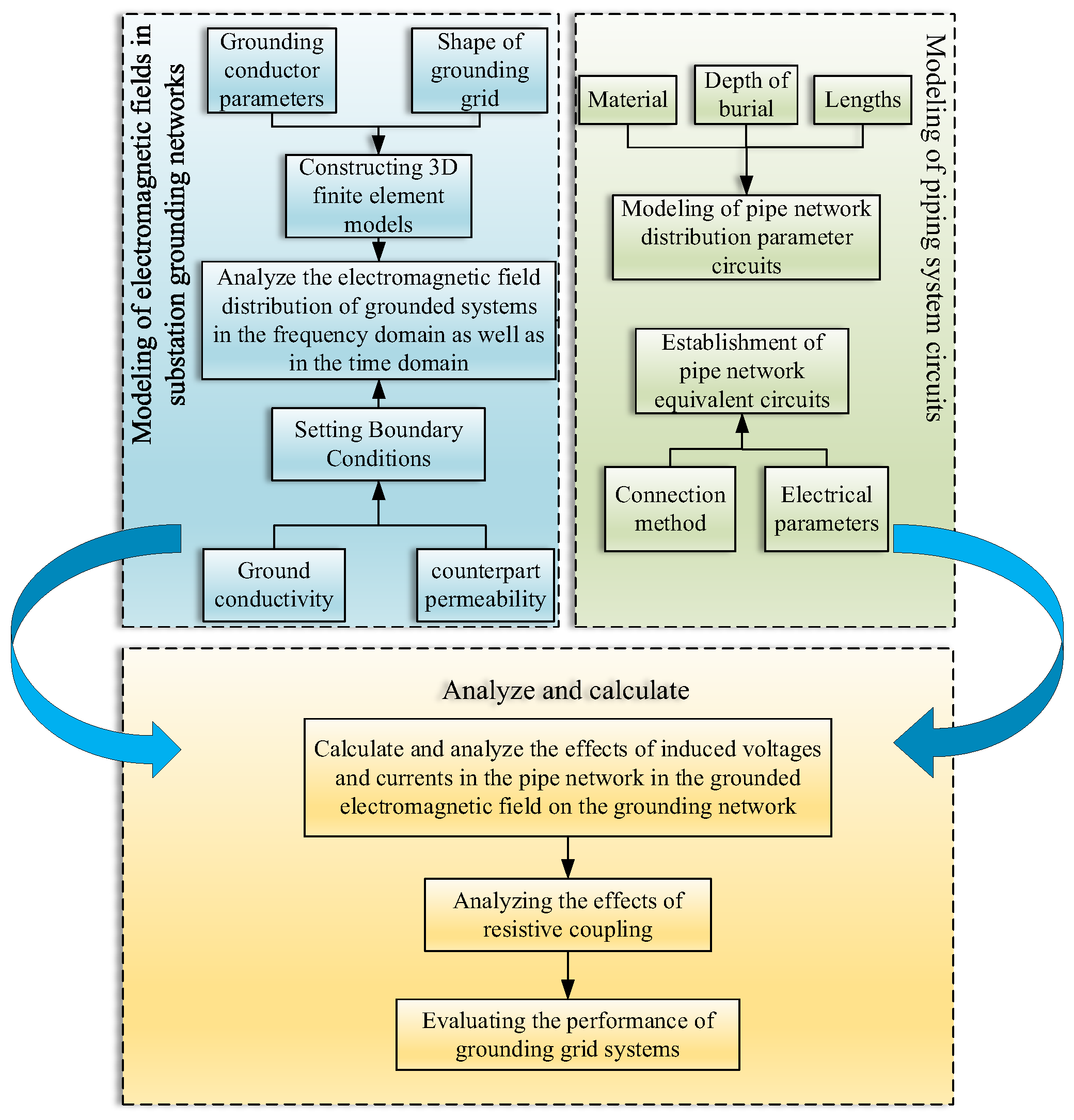
For complex urban pipeline networks, this study employs a field–path coupling approach. By simplifying the remote pipeline network into an equivalent circuit model, the direct solution of an extremely large matrix is effectively avoided, significantly enhancing simulation efficiency. The methodological topology of the optimisation strategies involved in analysing and manipulating the variables of the substation earthing grid and peripheral pipe network is illustrated in Figure 1. This topology defines the recursive logic between field analysis and circuit validation to ensure all safety parameters converge within theoretical limits.
As demonstrated in Figure 1, when analysing the impact of the pipe network surrounding the substation on the grounding network’s resistive coupling, it is imperative to initially establish the electromagnetic field model of the grounding network and the circuit model of the pipe network system through the fundamental performance parameters of the grounding network and the pipe network, respectively.

2.2. Resistive Coupling Analysis Method

This study focuses on analysing the resistive coupling effect in scenarios where underground metallic pipelines exist in the vicinity of substation earthing grids. This is because, in the vicinity of substations, the conducted earth potential rise constitutes the dominant component of the elevated potential within the pipeline network. Although neglecting inductive coupling theoretically simplifies matters to some extent. However, under the close-proximity coupling conditions demonstrated in this case study, its impact on the overall potential rise is relatively minor. Resistance coupling adequately reflects the core safety risks within the pipeline network. The potential vector equations for the midpoints of each section of the grounding grid and the metal pipe are established separately:
U 0 = R 00 I + R A 0 I A U A = R 0 A I + R AA I A
where U 0 and U A represent the potentials of the grounding network and the surrounding metal pipe network; R 00 and R AA represent the resistance coefficient matrices of the grounding network and the metal pipe network itself; I and I A represent the stray current vectors at each end of the grounding network and the surrounding metal pipe network; R A 0 represents the matrix of mutual resistance coefficients for the effect of metallic pipes on the grounding grid; and R 0 A represents the matrix of mutual resistance coefficients for the effect of the grounding grid on the metallic pipe.
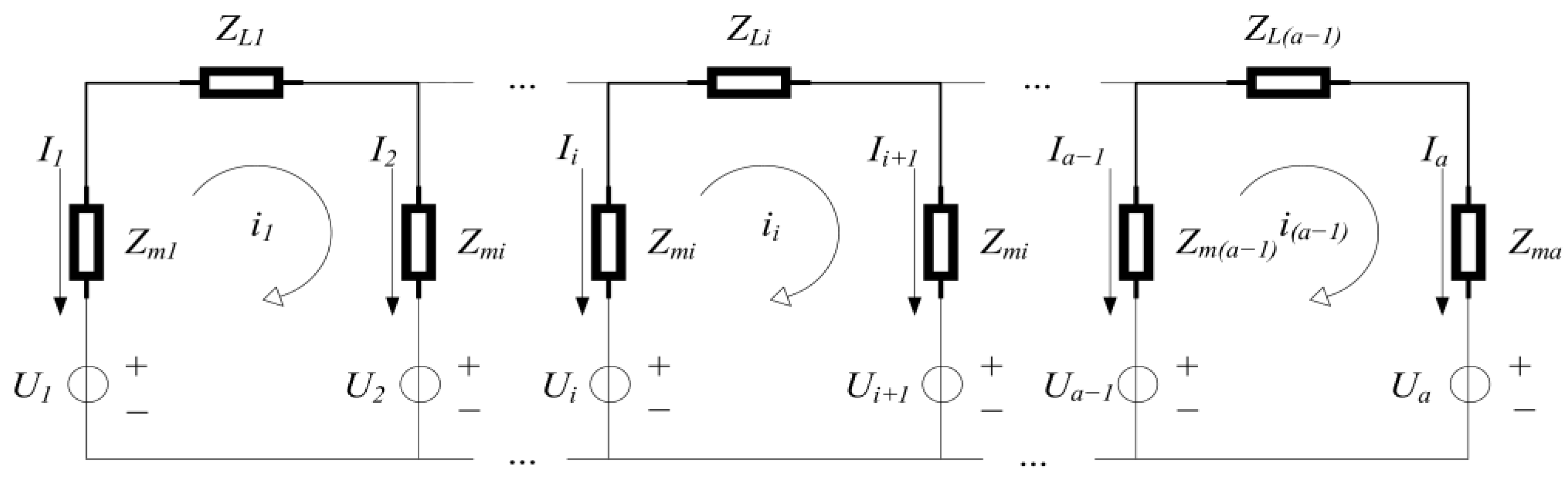
A metal pipe equivalent circuit is modelled as shown in Figure 2.
This is obtained from Kirchhoff’s law:
T A U A = I A
where T A represents the metal pipe equivalent circuit matrix.
The grounding network can be viewed as an isotope, and with the magnitude of the injected current i set known, one obtains
u 0 = U 01 = U 02 = = U 0 n i set = I 1 + I 2 + + I n
The collation reduces to matrix form:
R 00 R A 0 1 0 R 0 A R AA 0 1 0 E 0 T A 1 1 0 0 I I A U 0 U A = 0 0 0 i set
In the event of a pipe network comprising multiple metal pipes surrounding the substation grounding grid, the expression for the relationship between their potentials can be derived as follows:
U 0 = R 00 I + R A 0 T A U A + R B 0 T B U B + + R K 0 T K U K U A = R 0 A I + R AA T A U A + R BA T B U B + + R KA T K U K U B = R 0 B I + R AB T A U A + R BB T B U B + + R KB T K U K U K = R 0 K I + R AK T A U A + R BK T B U B + + R KK T K U K
where U 0 U K is the potential distribution of the grounding network and metal pipe network; T A T K is the equivalent circuit matrix of the metal pipe network; R i j (i, j = 0, A, …, K) is the matrix of resistance coefficients formed by the grounding network and the metal pipe network itself and by each other; and K is the number of pipes in the metal pipe network.
Analogous to the case of a single metal pipe, the derivation yields the final matrix equation as:
R 00 R T 1 R P G T E 0 1 0 0 I U u 0 = 0 0 i set   A K
where i set   is the total dissipation value of the grounding grid; E is a unit array of order m; and m is the number of pipe segments after dissecting the metal pipe network.
R T = R A 0 T A R B 0 T B R K 0 T K
R P = R 0 A R 0 B R 0 K
G = R AA R BA R KA R AB R BB R KB R AK R BK R KK
T = T A 0 0 0 T B 0 0 0 T K
U = U A U B U K
Solving this m + n + 1 dimensional matrix equation yields the grounding network bulk current distribution I, potential U 0 , and the metal pipe network potential distribution.
The grounding grid potential–dispersion relation matrix can be expressed as follows in the absence of a metal pipe network surrounding the grounding grid:
R 00 1 1 0 I u 0 = 0 i s e t
The potential u 0 of the grounding grid and the bulk flow distribution vector I are obtained by solving for the absence of pipe influence. Then the grounding resistance of the grounding grid can be further solved:
R = u 0 i s e t

3. Engineering Simulation Analysis

This paper is based on the actual transformation project of a substation grounding network in Shandong. The paper sets out the basic parameters of the substation grounding network and the surrounding soil resistivity. It also establishes an equivalent model of the substation grounding network and the surrounding metal pipe network system. Furthermore, it studies the impact of resistive coupling between the two.

3.1. Project Overview

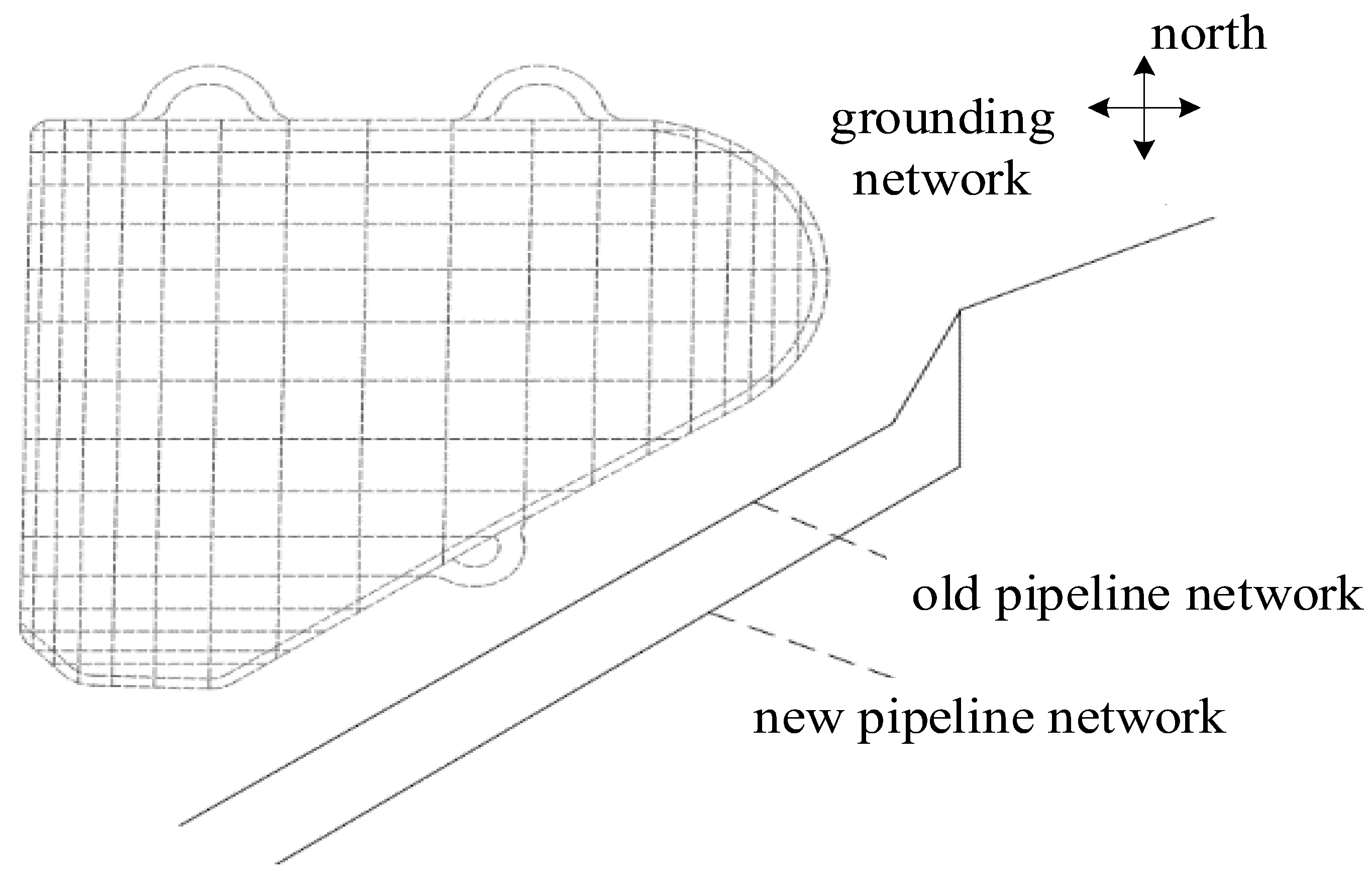
According to engineering information, the substation is currently set up in the station: four deep well grounding bodies, a vertical grounding body using Φ20 mm copper-plated steel rods, depth of 40 m, and a horizontal grounding body using 40 × 5 flat copper, to take the unequal spacing of the laying, a depth of burial of 0.8 m or so. Unlike common rectangular grounding grids, the overall shape of this substation grounding grid is close to a right triangle. When a short-circuit fault occurs in the substation, the fault current into the ground through the grounding grid is about 15 kA. Additionally, this study uniformly adopts 0.4 s as the duration of the short-circuit fault. This value is applied synchronously in both the theoretical calculation of safety limits and the parameter configuration of software simulation models. In the southeast direction of the grounding network, there are two old and new gas pipelines, the old gas pipeline distance from the nearest grounding network is about 15 m or so, the new pipeline distance from the grounding network is about 24 m, does not meet the requirements of GB50028 in the underground gas pipeline and 220 KV substation grounding body not less than 30 m distance. The old pipeline crossing section placed in DN700 ductile iron casing, new and old pipelines are Φ529 mm spiral seam welded steel pipe, wall thickness of 8.0 mm, using a 3-layer PE anticorrosion layer, the thickness of the anticorrosion layer of 3 mm, resistivity of 1 × 10¹³ Ω-m, the pipeline burial depth of 1.2 m. The length of the new and old pipes parallel to the grounding grid is about 120 m. The model of grounding network and pipeline is shown in Figure 3.
A dual-layer soil resistivity model of the geographical environment at the substation site was derived from field measurement data, as detailed in Table 1. The established two-layer model assumes that each soil layer constitutes an isotropic homogeneous medium. Sensitivity studies indicate that the computational results are relatively sensitive to upper soil parameters. Should the measured thickness of the topsoil deviate by 20%, the calculated values for touch voltage and step voltage will exhibit fluctuations of approximately 10–15%. This underscores the importance of conducting actual measurements of soil parameters.
The utilisation of CDEGS 15.4 and ETAP 19 power system analysis software is predicated on the premise that these programmes are instrumental in modelling and analysing the substation grounding network and the surrounding underground metal pipe network structure. This assertion is substantiated by the empirical evidence derived from measured underground soil resistivity data. The employment of these software programmes entails the execution of simulation calculations, the objective of which is to ascertain the potential rise in the substation and the metal pipe network, in addition to other safety parameters. A concomitant study and analysis of the impact of resistive coupling between the grounding network system and the metal pipe network system is also recommended.

3.2. CDEGS Simulation Analysis

The CDEGS software package (MALZ) solves Maxwell’s equations using the method of moments (MoM). In power–frequency fault analysis, this method characterises soil frequency-dependent properties through complex resistivity and complex permittivity measurements. Combined with frequency-domain Green’s function calculations for quasi-static field distribution, it effectively accounts for soil skin effects and the influence of electromagnetic propagation on ground potential distribution. In accordance with the two-layer soil model that was presented in the preceding section, the substation grounding network and the surrounding underground metal pipes are modelled and analysed using the CDEGS simulation programme. This programme combines the material and structure of the grounding system and the metal pipes [15].
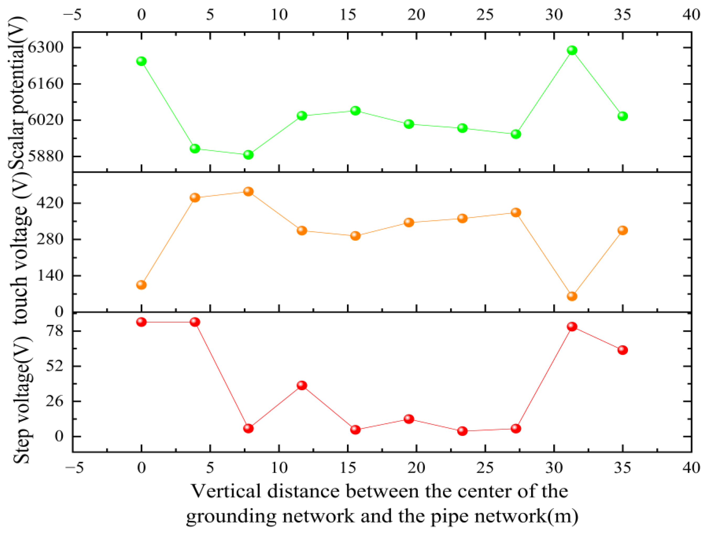
Initially, ten equal measurement points are established at the centre of the grounding network along the path perpendicular to the direction of the metal pipe. Subsequently, a 15 KA fault current is conducted, and the alterations in scalar potential, touch voltage, and step voltage along the path are simulated and calculated, as illustrated in Figure 4.
In the event of a short-circuit fault occurring in the substation, with a resulting fault current of 15 kA, the scalar potential from the centre to the edge of the grounding grid exhibits an uneven distribution trend. The touch voltage is lower at the centre point (104.62 V) and fluctuates above and below 400 V along the remainder of the path. The step voltage can reach a maximum of 84.6 V at the centre point, with all other locations along the path falling below this value. The step voltage reaches a minimum of 3.98 V, with a tendency to increase closer to the pipe.
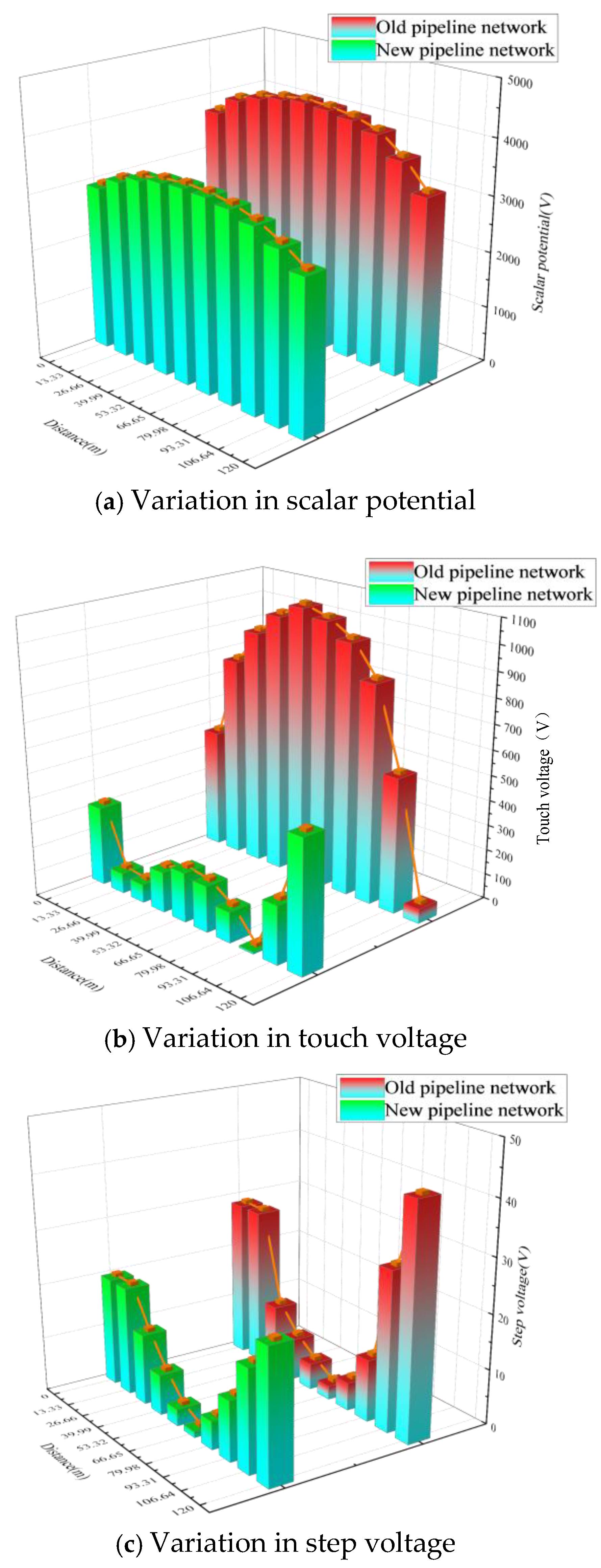
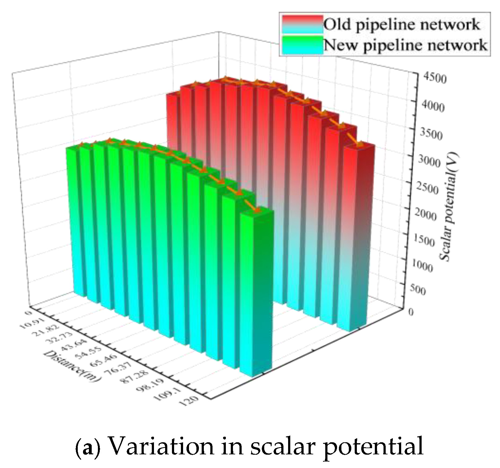
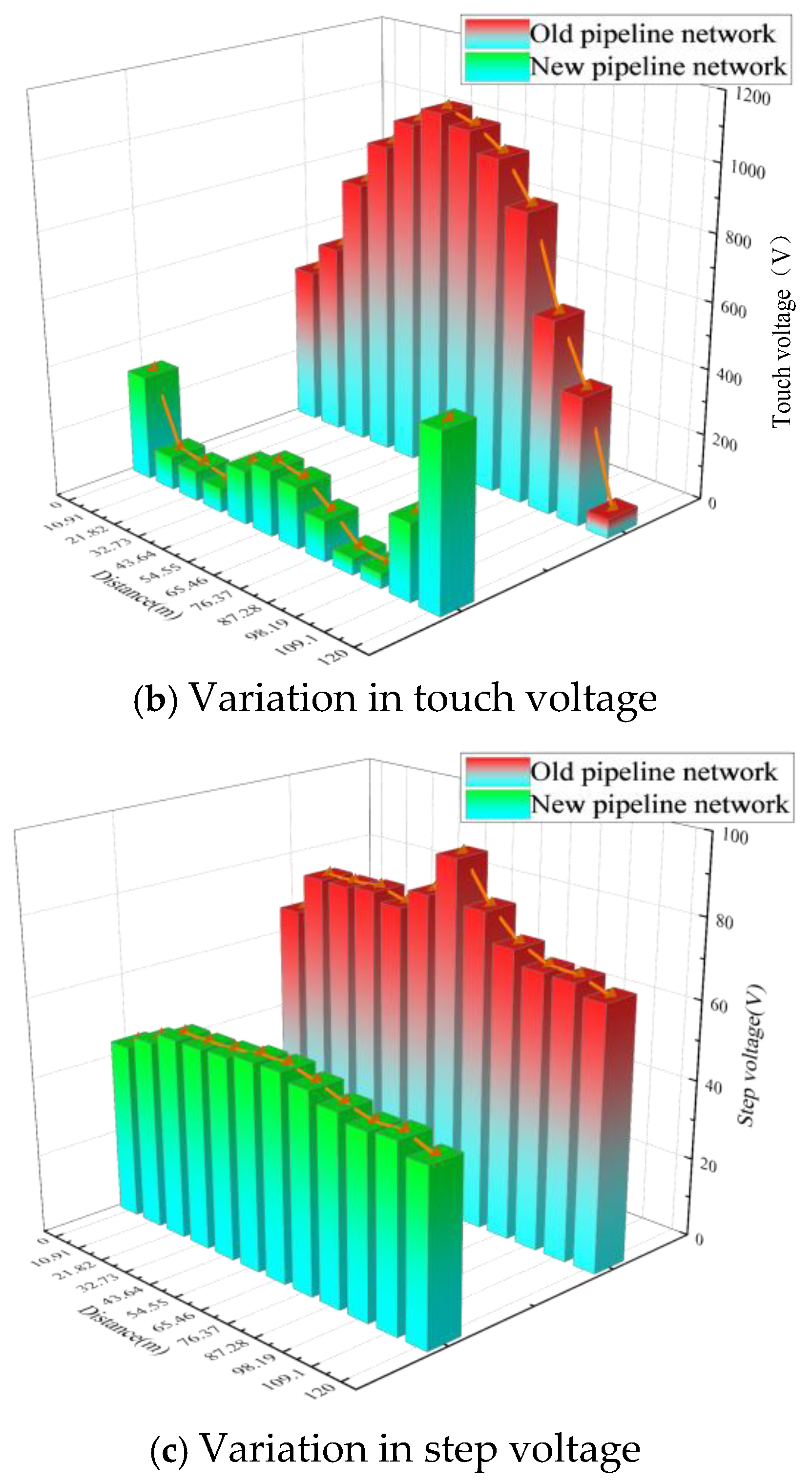
Conversely, the antiquated and contemporary metal conduits are oriented in parallel with the grounding network from a northerly direction, with a parallel length of approximately 120 m. In the context of a 15 kA fault current, the antiquated conduits are positioned in parallel with the grounding network from the northerly direction of the map as the initial point. The trend of the pertinent performance parameters of the contemporary and antiquated conduits under a parallel distance of 120 m is simulated and calculated, as illustrated in Figure 5.
In the event of a fault current flowing in, the scalar potential exhibits a tendency to be high in the middle and low at both ends for both the old and new pipe networks. With regard to the touch voltage, the trend of the old pipe network is closely aligned with the scalar potential; conversely, the trend of the new pipe network fluctuates more significantly, exhibiting high values at both ends and low values in the middle. With regard to the step voltage, both the existing and the proposed pipe networks demonstrate a tendency towards low central values and elevated lateral values. A comparison of the performance parameters of the two networks reveals a higher trend in the old network compared to the new one.
The primary cause of the aforementioned trend is attributable to the presence of a low-resistance grounding conductor. This results in a reduction in the equivalent soil resistivity in the vicinity of the conductor. Consequently, the grounding network centre to the edge of the ground potential rise exhibits an uneven distribution trend. The high-resistance anti-corrosion coating on the surface of metal pipelines physically blocks the path for current to enter the pipe body from the soil. Under this high-impedance shielding effect, the longitudinal current in the pipeline network is extremely small. Ground potential rise is primarily transmitted through distributed capacitive coupling or weak points in the coating. This results in a more gradual potential distribution along the pipeline network compared to uncoated conditions, with a significant reduction in amplitude. The older pipeline is in closer proximity to the grounding network. Consequently, when a substation short-circuit fault exceeds a certain threshold, the older pipeline is subject to the coupling effect. This results in the three voltage parameters of the older pipeline exceeding those of the newer pipeline.

3.3. ETAP Simulation Analysis

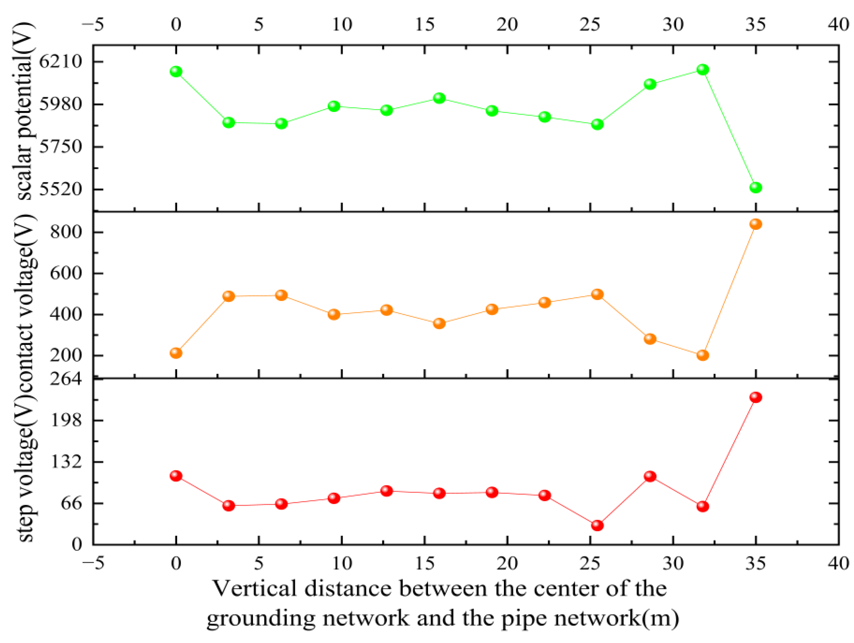
The ETAP software is a comprehensive graphical interface that facilitates the simulation and analysis of power systems. This software has been developed by OTI [16,17,18]. In accordance with the double-layer soil model set out in the preceding section and the data concerning substation and pipeline, the finite element method modelling and analysis module of the ETAP analysis programme is utilised to model and analyse the irregular grounding grid system and metal pipeline. Furthermore, the programme is employed to study the trend of ground potential rise, touch voltage, and step voltage change from the centre of the grounding grid to the edge of the grounding grid that is parallel to the metal pipeline, and along the old and new metal pipelines. Twelve equal points from the centre to the edge of the grounding network, the old pipeline, and the path of the new pipeline were selected for the calculation of the relevant safety parameters (see Figure 6).
As demonstrated in Figure 6, the scalar potential attains its maximum at 0 m, after which the voltage undergoes slight fluctuations with an increase in distance, yet remains largely stable in general. The voltage begins at 0 m, subsequently rises, and then fluctuates with an increase in distance, demonstrating a certain degree of variability. The step voltage undergoes a decrease before exhibiting fluctuations in conjunction with an increase in distance, exhibiting a relatively consistent overall trend.
The initial phase of the project involved the establishment of a pipeline in the north-eastern region of the map, which was then integrated with the grounding network. The utilisation of ETAP software simulation facilitated the calculation of the 120-m parallel distance. The subsequent analysis of the performance parameters of both the new and old pipelines is illustrated in Figure 7.
As demonstrated in Figure 7, the scalar potential and touch voltage trends obtained using the ETAP software are essentially analogous to those obtained in the preceding section. However, the trend of the step voltage is notably smoother and exhibits a pronounced middle and low sides.
Simulation results demonstrate a high degree of consistency between the two software packages. The specific comparative data is shown in Table 2. The relative deviation of each key safety parameter was maintained at approximately 5%, thereby validating the model’s reliability. In comparison with the simulation of CDEGS, the ETAP simulation demonstrates a largely congruent alteration in the performance parameters of the grounding network. However, the trend of this alteration is less pronounced, and the scalar potential distribution from the centre to the periphery of the grounding network exhibits increased uniformity, devoid of substantial fluctuations. Furthermore, the touch and step voltages are reduced at the centre, while a discernible upward trend is evident near the pipeline, accompanied by significant fluctuations in the alteration. The key performance parameters of the pipe networks demonstrated a clear increasing trend at closer linear distances from the grounding network. Furthermore, the fluctuations in changes were significantly smaller for the new pipes than for the older ones. Nevertheless, a discrepancy exists between the two in terms of the simulation value, which is primarily attributable to the ETAP for irregular grounding network modelling and finite element algorithm analysis. Furthermore, it encompasses the calculation of grounding system-related parameters and the geodetic structure of the mesh partition. Conversely, the CDEGS software, founded on the method of moments calculations, is exclusively employed for the region of the grounding network and its underground geodetic stratification structure in the engineering simulation. Conversely, CDEGS software facilitates the establishment of observation points in the construction of grounding network and pipeline models, thereby optimising design processes. Consequently, CDEGS software is employed to model resistive coupling analysis and other influencing factors in the subsequent analysis [19,20,21,22,23,24].

4. Optimised Design of Protective Measures

In order to further enhance the transformation of the substation grounding network in the project, the impact of the surrounding metal pipe network on the grounding network is currently being investigated from multiple perspectives.

4.1. Analysis of Influencing Factors

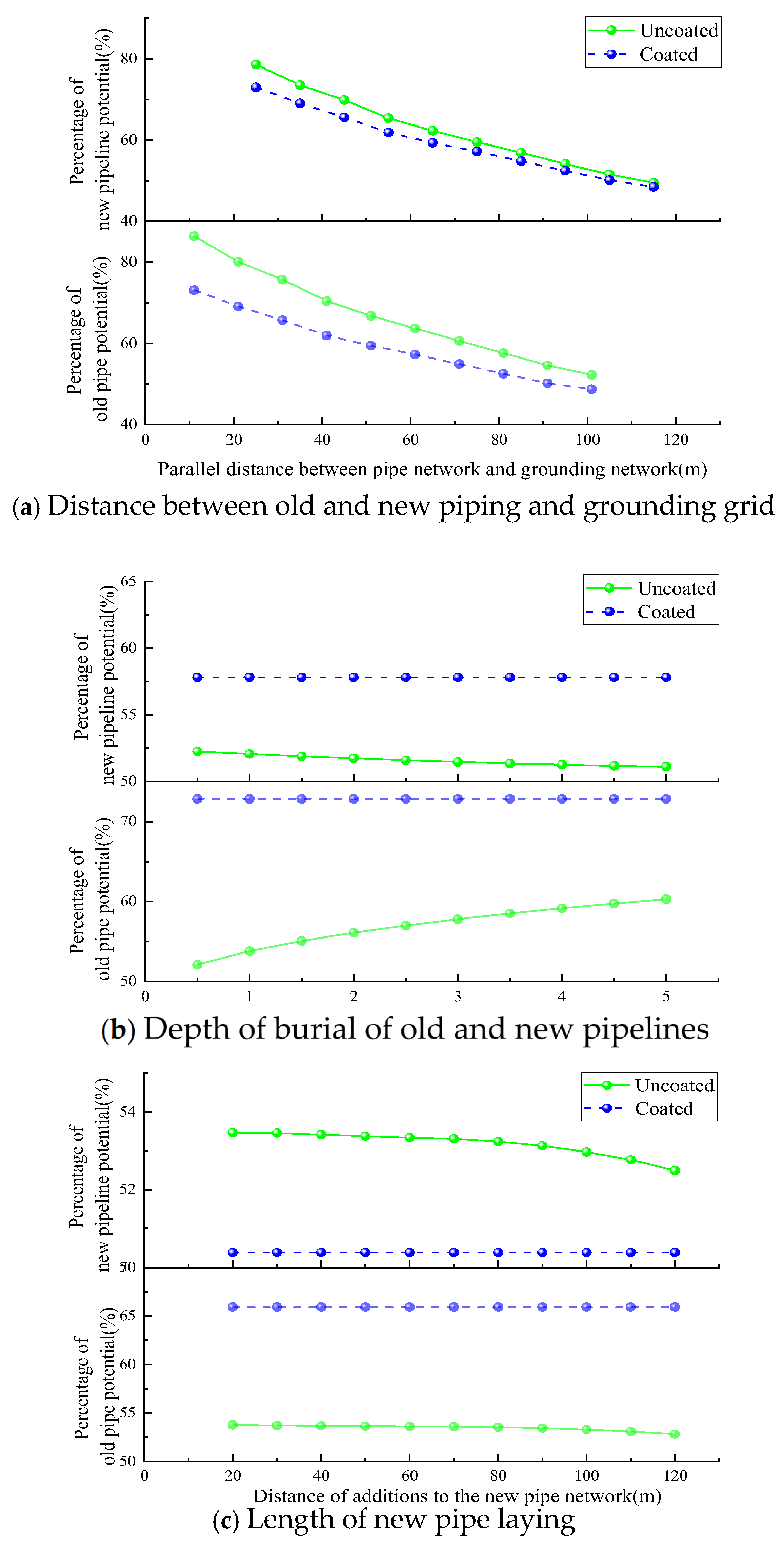
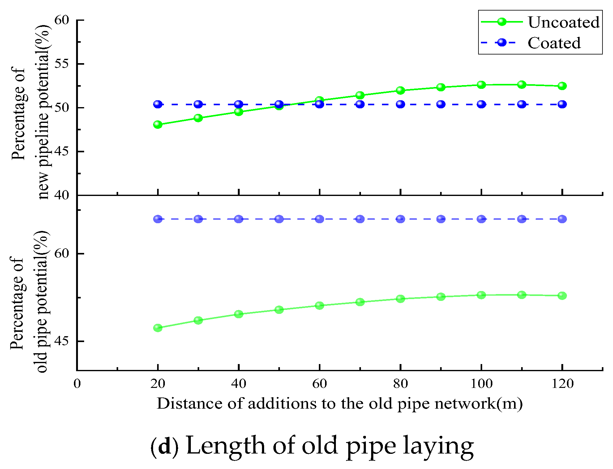
In accordance with the substation grounding network and the surrounding metal pipe network model set out in the preceding section, the same fault current of 15 KA is passed. The potential of the grounding network is used as a benchmark, and the new and old metal pipe networks are analysed as a whole. The new and old grounding networks are studied respectively by changing the parallel distance between the pipe networks and the grounding network, the laying length of the new and old pipe networks, and the degree of depth of the burial. The influence of the layers of the pipe networks based on the 3-PE corrosion layer is also considered. It should be emphasised that the distance referred to here denotes the horizontal distance between the edge of the earthing grid and the centre line of the pipeline network. In the simulation, the burial depth remains constant while only the horizontal displacement is altered. The percentage change in the potential is shown in Figure 8.
As demonstrated in Figure 8a, an increase in the distance between the pipe and the grounding network results in a reduction in the impact of the resistive coupling between the two. Consequently, the percentage of the pipe’s potential decreases, allowing for a reduction in the addition of the coating to mitigate the impact of the resistive coupling. As demonstrated in Figure 8b, the percentage of potential of the pipe with additional coating remains largely unaltered as the depth of the pipe increases. In contrast, without additional coating, the percentage of potential of the old pipe close to the grounding grid with respect to the grounding grid gradually increases, while the percentage of potential of the new pipe away from the grounding grid with respect to the grounding grid gradually decreases. As demonstrated in Figure 8c, in the absence of a coating, as the length of the old pipe is reduced, the percentage of potential between the old and new pipes and the grounding grid gradually decreases. However, upon the addition of a coating, the alteration in length of the old pipe exerts minimal influence on the percentage of potential between the old and new pipes and the grounding grid. As demonstrated in Figure 8d, in the absence of a coating, a decrease in the length of the new pipe results in a marginal increase in the percentage of potential between the old and new pipes and the grounding grid. Conversely, the addition of a coating renders the length of the new pipe essentially inconsequential to the percentage of potential between the old and new pipes and the grounding grid.

4.2. Installation of Additional Vertical Grounding Electrodes

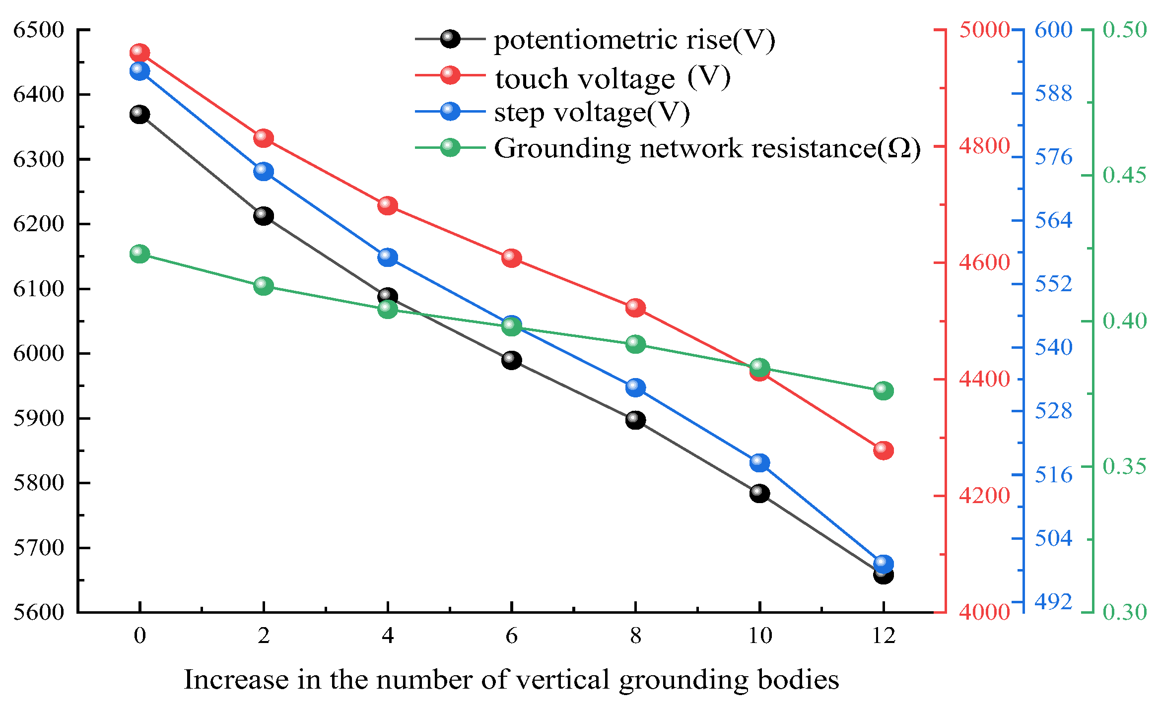
The original grounding network contains four vertical grounding bodies; on the grounding network 2 to 12 vertical grounding bodies were added, grounding body conductivity of 100 S/m, thermal conductivity of 234, melting temperature of 1083 °C, resistivity of 1.72 Ω-m, heat capacity of 3.42 J/K, length of 40 m, fault clearing time of 0.4 s, and body weight of 50 kg. The changes in the performance parameters of the grounding system after adding different numbers of vertical grounding bodies are analysed and shown in Figure 9:
As demonstrated in Figure 9, an increase in the number of vertical grounding bodies leads to a decline in the ground potential rise, touch voltage, step voltage, and grounding resistance of the grounding network. Furthermore, an augmentation in the number of vertical grounding poles by 12 resulted in a reduction in the ground potential rise by 6.8%. Consequently, under circumstances that permit, the incorporation of additional vertical grounding bodies into the grounding system can be contemplated to mitigate grounding resistance.

4.3. Addition of Surface Material

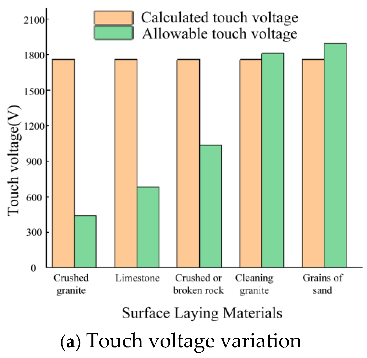
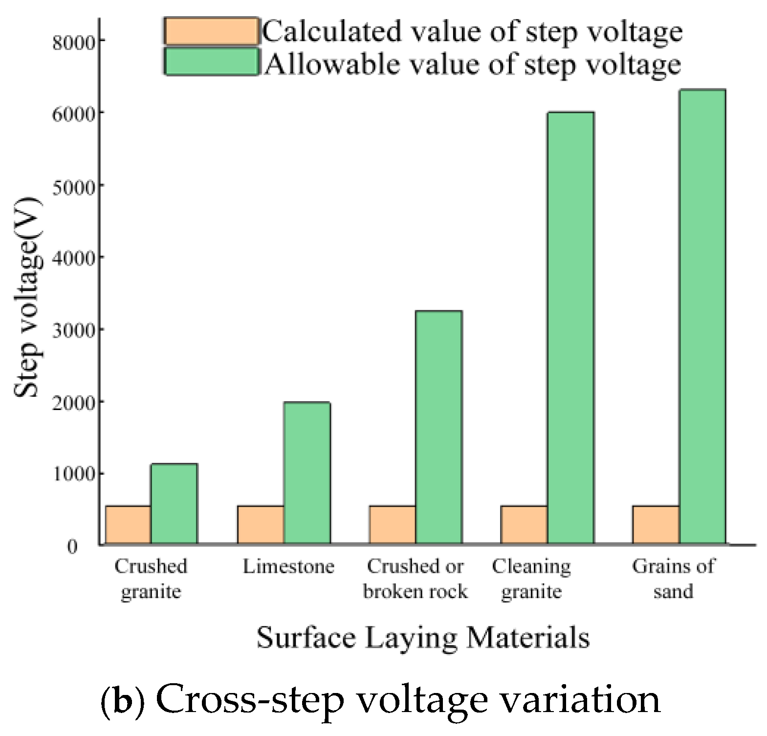
The construction of the new vertical grounding body in the completed substation poses a significant challenge. To address this challenge, an analysis of the substation and the pipeline above the surface is conducted. This analysis involves the use of five types of high-resistance materials, each with a thickness of 0.2 m. The objective of this analysis is to determine the optimal layering of these materials, taking into account the calculated values of the material above the touch voltage and the corresponding permissible values. The results of this analysis are presented in Figure 10a, which illustrates the layering of materials above the calculated step voltage and permissible value. Figure 10b provides a similar representation, showing the layering of materials above the calculated step voltage and permissible value.
As demonstrated in Figure 10, with an increase in the resistivity of the surface due to the presence of additional surface material, the material’s role becomes predominantly insulating. This ensures that the material above the touch voltage and the permissible increase in the safety voltage is effective in safeguarding the personal safety of staff. It is evident that, of the five materials under consideration, the 0.2 m thick crushed gravel layer with a resistivity of 8534.4 Ω-m exerts the most significant effect on the improvement of the permissible values of touch and step voltages. A comparison of the specific values is provided in Table 3.
As illustrated in Table 3, the permissible touch voltage threshold is established at 1883.8 V, while the safe step voltage limit is determined to be 7043.2 V under conditions where the station is surfaced with a 0.2-metre layer of crushed sand and gravel. In the absence of a gravel layer, the safe touch voltage limit is set at 193.1 V, while the safe step voltage limit is 282.5 V. The implementation of a high-resistance crushed sand and gravel layer on the ground surface, situated above the grounding network and metal piping, has been demonstrated to be an effective method of reducing step and touch voltages below the established safety limit. This approach serves to ensure the safeguarding of personal safety. It should be noted that the surface layer primarily enhances safety by increasing the human body’s tolerance capacity. Consequently, the permissible voltage in the table increases significantly, whilst the calculated voltage of the earthing system itself remains unchanged.

5. Conclusions

This study integrates engineering practice with a field–circuit coupling methodology to establish a rigorous mathematical model. By synergizing the analytical capabilities of CDEGS and ETAP, the research investigates the distribution of fault currents within substation earthing networks and the consequential resistive coupling effects on adjacent metallic pipeline networks. The primary findings and future outlook are summarized as follows:
(1)
Resistive Coupling Dynamics: Upon the injection of fault currents into the earthing system, the resistive coupling between the earthing grid and peripheral metallic pipelines facilitates a complex, interdependent current distribution path. This phenomenon significantly influences the current partitioning across both infrastructures, leading to observable fluctuations in their critical performance parameters.
(2)
Simulation Consistency: Comparative analysis reveals that CDEGS and ETAP exhibit a high degree of consistency in capturing the performance trends of the earthing system. A marginal numerical deviation of approximately 5% was observed between the two platforms, validating the reliability of the synergistic simulation approach.
(3)
Optimization Strategies: For renovation projects where extensive excavation is constrained, the implementation of high-resistance coatings and vertical earthing electrodes has been demonstrated to effectively optimize system performance. Furthermore, enhancing the earthing network’s surface parameters and utilizing high-resistivity gravel layers can significantly improve the safety metrics of both the earthing grid and adjacent metallic pipelines.
(4)
Academic and Industrial Significance: The methodology and findings presented in this paper offer valuable theoretical references and practical guidance for the design of earthing poles in HVDC transmission projects and converter station earthing networks.

Author Contributions

The paper investigation, resources, data preparation, writing—original draft preparation, writing—review and editing, and visualization were undertaken by C.M. and M.S. The paper conceptualization, software, validation, formal analysis, methodology were done by C.M., M.S. and Z.Z. Supervision, project administration, and final check for approval of the version to be published were conducted by J.L. and L.S. All authors have read and agreed to the published version of the manuscript.

Funding

This research work is supported by the National Natural Science Foundation of China (52477178).

Data Availability Statement

Data will be made available on request.

Conflicts of Interest

The authors declare no conflicts of interest.

Abbreviations

The following abbreviations are used in this manuscript:
CDEGSCurrent Distribution, Electromagnetic Fields, Grounding and Soil Structure
ETAPElectrical Transient and Analysis Program

References

  1. Liu, M.; Xie, Y.; Chen, Y.; Trinchero, R.; Stievano, I.S. Modeling of Induction in Integrated Power-Gas Systems Due to Geomagnetic Disturbances. IEEE Trans. Power Deliv. 2023, 38, 3847–3859. [Google Scholar] [CrossRef] [Scilit]
  2. Wang, L.; Liu, Z.; Song, M.; Zheng, X.; Li, C.; Yao, X.; Guo, D.; Ma, C. Impact of Newly Built Grounding Grid on the Original Grounding Grid Based on the Method of Moments. Power Syst. Clean Energy 2023, 39, 32–39, 46. [Google Scholar] [CrossRef] [Scilit]
  3. Kettunen, L. Fields and circuits in computational electromagnetism. IEEE Trans. Magn. 2001, 37, 3393–3396. [Google Scholar] [CrossRef]
  4. Ma, C.; Yao, X.; Wang, L.; Zheng, X.; Song, M.; Li, C.; Sun, L.; Guo, D. Impacts of the pipe network around the substation and the new grounding system on the characteristic parameters of the original grounding grid. Power Syst. Clean Energy 2024, 40, 21. [Google Scholar]
  5. Zhang, H.; Wang, F.; Jin, Z.; Sun, Y. Influence of underground metal pipes on grounding resistance and its measurement in substation grounding network. Power Grid Technol. 2011, 35, 134–140. [Google Scholar]
  6. He, J.; Yu, S.; Zeng, R.; Zhang, B. Influence of underground structures near substations on grounding resistance measurement. High Volt. Electr. Appar. 2004, 40. [Google Scholar]
  7. Li, Y. Research on Short Distance Measurement Method for Grounding Resistance of Large Substation Grounding Grid. Ph.D. Thesis, Department of Electrical Engineering, Zhengzhou University, Zhengzhou, China, 2017. [Google Scholar]
  8. Li, Z. Influence of underground metal pipes on grounding resistance and its measurement in substation grounding networks. Autom. Appl. 2023, 64, 71–73. [Google Scholar]
  9. Qi, L.; Zhang, B.; Cui, X. Analysis of resistive coupling of substation grounding network to nearby building grounding network and direct buried metal pipeline. Power Syst. Technol. 2002, 26, 46–49. [Google Scholar]
  10. Cheng, M.; Qin, W.; Zhu, X.; Wang, Z. Magnetic-Inductance: Concept, Definition, and Applications. IEEE Trans. Power Electron. 2022, 37, 12406–12414. [Google Scholar] [CrossRef] [Scilit]
  11. Zhan, B.; Cui, X.; Zhao, Z. Analysis of grounding grids at large scale substations in frequency domain. Proc. CSEE 2002, 22, 59–63. [Google Scholar]
  12. Hu, H.; Luo, R.; Fang, M.; Zeng, S.; Hu, F. A new optimization design for grounding grid. Int. J. Electr. Power Energy Syst. 2019, 108, 61–71. [Google Scholar] [CrossRef] [Scilit]
  13. Zhang, P.; Zhang, B.; Wang, J.; Huang, W.; Chen, H.; Xiong, X. Short-term risk assessment for a power substation considering the time-varying operation conditions of power equipment. Power Syst. Prot. Control 2021, 49, 73–81. [Google Scholar]
  14. Huangfu, Y.; Wang, S.; Qiu, J.; Zhang, H.; Wang, G.; Zhu, J. Transient Performance Analysis of Induction Motor Using Field-Circuit Coupled Finite-Element Method. IEEE Trans. Magn. 2014, 50, 873–876. [Google Scholar] [CrossRef] [Scilit]
  15. Kamberaj, H. Electromagnetism: With Solved Problems. In Undergraduate Texts in Physics; Springer International Publishing: Cham, Switzerland, 2022. [Google Scholar]
  16. Liu, H.; Mitolo, M.; Qiu, J. Ground-Fault Loop Impedance Calculations in Low-Voltage Single-Phase Systems. IEEE Trans. Ind. Appl. 2014, 50, 1331–1337. [Google Scholar] [CrossRef] [Scilit]
  17. Fang, J.; Chen, H. Status quo of substation grounding and related design technology. East China Electr. Power 2009, 37, 2010–2015. [Google Scholar]
  18. Ma, C.; Song, M.; Yin, B.; Liu, L.; Yang, M.; Sun, L. Optimizing the design of a new substation grounding network by combining IEEE std80-2000 and CDEGS. Power Syst. Prot. Control 2024, 52, 131–139. [Google Scholar]
  19. Calvin, H.A.; Virostek, S.P. Railgun electromagnetism. IEEE Trans. Magn. 1995, 31, 107–112. [Google Scholar] [CrossRef] [Scilit]
  20. Lee, C.-H.; Chang, C.-N.; Jiang, J.-A. Evaluation of Ground Potential Rises in a Commercial Building During a Direct Lightning Stroke Using CDEGS. IEEE Trans. Ind. Appl. 2015, 51, 4882–4888. [Google Scholar] [CrossRef] [Scilit]
  21. Xue, J.; Huang, H.; Cai, L.; Xu, Z.; Fang, Y.; Wang, J.; Fan, Y. Lightning Impulse Impedance and Surface Potential Distribution of 10 kV Distribution Line Tower: Field Test and Simulation. IEEE Trans. Power Deliv. 2022, 37, 415–422. [Google Scholar] [CrossRef] [Scilit]
  22. Lange, E.; Henrotte, F.; Hameyer, K. A Circuit Coupling Method Based on a Temporary Linearization of the Energy Balance of the Finite Element Model. IEEE Trans. Magn. 2008, 44, 838–841. [Google Scholar] [CrossRef] [Scilit]
  23. Chadebec, O.; Coulomb, J.-L.; Janet, F. A review of magnetostatic moment method. IEEE Trans. Magn. 2006, 42, 515–520. [Google Scholar] [CrossRef] [Scilit]
  24. Wang, C.; Liang, X.; Adajar, E.P. A Systematic Approach for AC Electromagnetic Interference Study Between Railways and Nearby Power Lines. IEEE Trans. Ind. Appl. 2023, 59, 5527–5538. [Google Scholar] [CrossRef] [Scilit]
Figure 1. Steps of analysing the impact of substation peripheral pipe network on grounding network resistive coupling.
Electronics 15 01257 g001
Figure 2. Pipeline equivalent circuit model.
Electronics 15 01257 g002
Figure 3. Model of grounding grid and pipeline.
Electronics 15 01257 g003
Figure 4. Variation in basic performance parameters of measurement points within the grounding network (CDEGS).
Electronics 15 01257 g004
Figure 5. Changes in key performance parameters of old and new pipelines (CDEGS).
Electronics 15 01257 g005
Figure 6. Variation in basic performance parameters of measurement points within the grounding network (ETAP).
Electronics 15 01257 g006
Figure 7. Changes in key performance parameters of old and new pipelines (ETAP).
Electronics 15 01257 g007aElectronics 15 01257 g007b
Figure 8. Percentage of potential for new and old pipes.
Electronics 15 01257 g008aElectronics 15 01257 g008b
Figure 9. Changes in safety parameters with the addition of a vertical grounding body.
Electronics 15 01257 g009
Figure 10. Changes in safety parameters with the addition of different surface materials.
Electronics 15 01257 g010aElectronics 15 01257 g010b
Table 1. Soil model around substations.
Layer of SoilDepth (m)Resistivity (Ω·m)
13.0120.3
282.0
Table 2. Quantitative comparison of CDEGS and ETAP simulation results.
Key ParametersCDEGS Calculated ValueETAP Calculated ValuesRelative
Deviation (%)
Grounding Resistance0.245 Ω0.258 Ω5.3%
Max GPR6289.5 V6012.8 V4.5%
Max Touch Voltage464.62 V493.3 V5.8%
Max Step Voltage84.6 V88.5 V4.6%
Table 3. Contact and step voltages before and after the addition of a gravel layer.
Touch Voltage (V)Step Voltage (V)
Calculated value in the absence of a surface layer1746.1597.8
Allowable value without surface layer193.1282.5
Calculated value with surface layer1746.1597.8
Permissible value when there is a surface layer1883.87043.2
Disclaimer/Publisher’s Note: The statements, opinions and data contained in all publications are solely those of the individual author(s) and contributor(s) and not of MDPI and/or the editor(s). MDPI and/or the editor(s) disclaim responsibility for any injury to people or property resulting from any ideas, methods, instructions or products referred to in the content.