1. Introduction
Doubly fed induction generators (DFIGs) have become the dominant type of wind turbine due to their numerous advantages, including good reactive power characteristics, high power generation efficiency, and low production costs. With the large-scale integration of wind power into the grid, and the resulting evolution of power systems into low-inertia systems [
1], DFIGs have gradually captured a large market share and become the main type of wind turbine currently in use [
2]. In currently available wind energy conversion systems, these turbines are widely used due to their superior advantages [
3]. The stator side of the doubly fed induction generator is directly connected to the power grid, while the rotor side is connected to the grid through a back-to-back converter composed of a Rotor-side converter (RSC) and a Grid-side converter (GSC). Because the stator side is directly connected to the power grid, changes in grid voltage directly affect the stator voltage [
4]. Furthermore, due to insufficient converter capacity, when a grid fault occurs, voltage changes can trigger a series of chain reactions in the doubly fed wind turbine, such as increased rotor current and power fluctuations. These changes are detrimental to the normal operation of the DFIG [
5]. Low-voltage ride-through (LVRT) of a DFIG means that when a fault or disturbance occurs in the power system and causes the grid voltage to drop to a certain range, the DFIG can continue to operate in grid connection instead of being immediately disconnected from the grid. Its purpose is to ensure that the wind farm does not aggravate the instability of the grid due to large-scale disconnection when the grid experiences a short-term voltage fluctuation. The ability of a DFIG to withstand LVRT events serves as a key parameter in assessing its overall operational quality.
In order to enable the motor to smoothly achieve LVRT, there are currently two main improvement methods: one method involves refining the control strategy, while the alternative necessitates the inclusion of hardware-based circuits. This paper mainly focuses on improving the control strategy. Among the current methods to improve the control strategy, the most widely used is Proportional−integral (PI) control. The PI controller monitors the error between the actual value (such as speed, current, and DC voltage) and the reference values in real time. The error is adjusted through Proportional (P) and Integral (I) operations to generate control signals and adjust circuit parameters [
6]. However, the PI control relies on fixed proportional and integral parameters. In the event of sudden faults (such as voltage sag), the dynamic performance may be insufficient, and the system response speed may be slow, preventing it from compensating for grid voltage fluctuations in time [
7]. On this basis, many scholars have proposed new control methods. Demagnetization control is one of the important control methods in LVRT of DFIGs. It maintains the rotor current within an appropriate range by rapidly adjusting the rotor-side converter to ensure the continuous existence of the rotor magnetic field, prevent the wind turbine from losing synchronization, and maintain a stable connection between the grid and the wind turbine. However, traditional demagnetization control requires complex real-time monitoring and rapid response mechanisms and has high requirements for the control system when the grid voltage changes rapidly. The demagnetization control scheme based on the virtual inductance self-demagnetization algorithm does not require the installation of additional hardware, and its passive action mechanism does not require fault flux information, which solves the problems existing in traditional demagnetization control and effectively augments the ability of the DFIG to withstand grid faults. Therefore, it has good cost-effectiveness and engineering feasibility [
8]. Another widely used control method is the decoupled feedforward control method. The advantage of the decoupled feedforward control method is that this method minimizes the mutual influence between different control links, thereby achieving the purpose of optimizing the control effect. This method enables the wind turbine to respond to low-voltage faults more smoothly and maintain output stability. Reference [
9] uses a decoupled feedforward control model with enhanced LVRT capability to avoid excessive current on the rotor side when the voltage drops, and uses the rotor electromotive force model to accurately and quickly predict the rotor-side current. However, the decoupled feedforward control involves the precise design and parameter adjustment of multiple control links, so the system is relatively complex and difficult to design and debug. The control method based on interference suppression refers to taking measures on wind turbine generator sets or other control systems to reduce or eliminate the negative impact of external disturbances on system operation. Reference [
10] proposed an LVRT control strategy based on interference suppression. This method is based on the state-dependent Riccati equation technology. The primary goal is to regulate the rotor-side converter to inject the necessary reactive power during transient events, while simultaneously managing the grid-side converter to stabilize the DC-link voltage. Therefore, the operational capability of wind power systems during low-voltage events has been greatly improved. The methods mentioned above, compared to model predictive control methods, often struggle to handle multiple complex faults correctly, thus requiring the development of more robust and precise control methods.
Currently, a widely studied control method is Model predictive control (MPC). MPC is an advanced control technique that utilizes the system’s mathematical model to predict future behavior and performs feedback correction through rolling optimization. It can effectively deal with the influence of uncertainty in the system and has been widely used in industrial processes. MPC offers significant advantages in LVRT of DFIGs. It mainly includes fast response, multi-objective optimization, good nonlinear processing ability and strong robustness. Reference [
11] proposed a model predictive control method for DFIGs based on state-space representation. This method establishes a state-space expression for the DFIG and uses it to predict the state trajectory of the generator. Reference [
12] proposed a demagnetization control method based on Explicit model predictive control (E-MPC) to enhance the LVRT capability of DFIGs. The designed E-MPC significantly accelerates the solution of the optimization problem, making it highly suitable for online control applications. Reference [
13] proposed a model predictive control-based active and reactive power optimization control strategy for wind farm fault ride-through. The proposed control strategy can quickly and effectively stabilize the voltage within a feasible range, improving the fault ride-through capability of the wind farm. Reference [
14] proposed a computationally Efficient finite-set model predictive voltage control (EFS-MPVC) scheme. Experimental results show that compared with traditional MPVC schemes, the proposed EFS-MPVC scheme reduces computational complexity and improves control performance. Reference [
15] conducted in-depth research on model predictive control in the control field, providing important references for this research. Reference [
16] proposed a Virtual vector-based modulated model predictive control (VV-M2PC) strategy for indirect matrix converters (IMC). Compared with the traditional M2PC, the VV-M2PC constructs and utilizes new virtual vectors to reduce current control errors. To optimize the DFIG response to low-voltage events, Reference [
17] introduces a strategy coupling MPC with a Dynamic Voltage Restorer (DVR), which effectively boosts the unit’s overall fault ride-through potential. In addition, the DVR can play a certain role in reactive power compensation in the circuit. However, the high cost of DVR equipment reduces the economic efficiency of this solution. Under asymmetric faults, traditional PI control cannot accurately track the AC reference value. Reference [
18] employs MPC for the rotor-side converter within a stationary reference frame to mitigate torque ripples and bolster the system’s LVRT performance. This strategy significantly enhances the precision of rotor current tracking during unbalanced grid faults, reducing electrical torque oscillation and improving the stability of the doubly fed wind turbine. In most cases, relying solely on software for control yields limited results; when dealing with complex failures, it is best to use a combination of hardware and software.
Additionally, under conditions of serious grid malfunctions, the successful fault ride-through of the grid-tied wind turbine cannot be assured solely through improvements to the control logic. In such cases, hardware protection circuits are needed. The control method based on the improved strategy does not require additional hardware circuits and is relatively low-cost, but its control capability is limited by the capacity of the unit converter, preventing effective ride-through operation during serious faults. Therefore, additional hardware protection measures must be adopted in the event of a serious fault [
19]. Reference [
20] used a crowbar circuit for control and studied the response capability of a doubly fed induction generator with an additional crowbar circuit under asymmetrical faults. Reference [
21] proposed a low-voltage ride-through control scheme for a doubly fed induction generator using stator crowbar circuit mode switching. The proposed control scheme ensures low-voltage ride-through of the doubly fed induction generator while effectively reducing rotor transient current, stabilizing the DC bus voltage, and providing reactive power to the grid. Reference [
22] studied the control methods of two different circuits, Crowbar and Chopper, and verified the effectiveness of the Crowbar and Chopper protection circuits. Reference [
23] conducted an in-depth analysis of the doubly fed induction generator circuit, derived an analytical expression for the resistance of the short-circuit protection device considering grid impedance, and verified the effectiveness of the proposed method through theoretical analysis and MATLAB simulation. Analysis shows that using such methods increases equipment costs, and engaging these devices locks the rotor-side converter, which is unfavorable for grid voltage recovery. However, these devices can effectively suppress rotor overcurrent and improve the fault tolerance of the generator.
Building upon the preceding analysis and grounded in traditional MPC, this study introduces a novel control strategy based on Model predictive current control (MP-CC) combined with a crowbar circuit. Through the analysis and research of the traditional MPC control strategy, the use of new control measures can control the parameters of the wind turbine in real time and can obtain the next operating status of the circuit in time, which can effectively improve the LVRT capability of the DFIG. Compared with the traditional PI control, it can achieve a better control effect on the circuit. The main innovations of this paper are as follows: Addressing the problem of insufficient prediction accuracy of traditional MPC under large fault disturbances, a fourth-order Runge–Kutta method is used for model discretization and solution, significantly improving the prediction accuracy of the rotor current during transient processes; secondly, a cost function design minimizing active and reactive power is proposed, utilizing the fast dynamic response characteristics of MP-CC to effectively suppress rotor current surges and solve the problem of overcurrent and grid disconnection that easily occurs during the recovery phase with conventional control strategies. By connecting a crowbar circuit to the rotor side of the DFIG, combining control strategies and hardware circuits, the stability of the DFIG is significantly improved. Simulation results show that using the improved control strategy, the low-voltage ride-through capability of the DFIG unit is significantly enhanced.
2. DFIG Mathematical Model
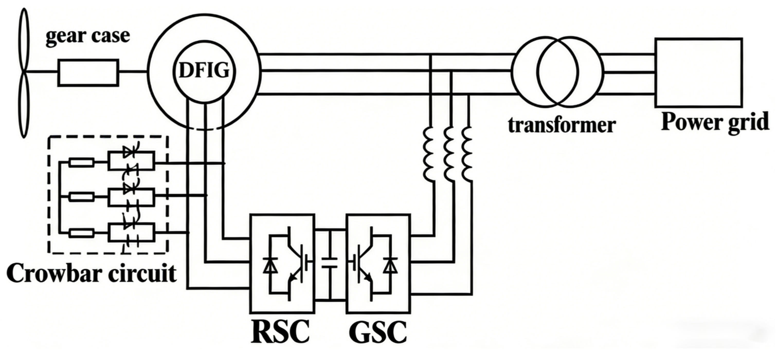
The DFIG described in this article uses a 3 MW doubly fed induction wind turbine. The terminal voltage of the DFIG is 690 V and the operating frequency is 50 Hz. The structure diagram of the DFIG system is shown in
Figure 1. The stator side of the DFIG is directly connected to the grid, so it is greatly affected by the grid voltage drop. The rotor side is connected to the grid through a back-to-back converter, and a crowbar circuit controlled by a circuit breaker is connected to the rotor side for control. The crowbar circuit is put into operation within a certain period of time after a system failure occurs to facilitate the smooth LVRT operation of the generation unit even under severe voltage dip conditions.
2.1. Wind Turbine Model
The initial step involves deriving the torque model. As per aerodynamic principles, the mechanical power captured by the wind turbine at a specific wind speed
v [
24] is expressed as follows:
where
Cp is the wind energy utilization coefficient,
R is the radius of the wind wheel, and
ρ is the air density. Then its output mechanical torque is as follows:
where
Tm is the mechanical torque output by the wind turbine, and
λ is the tip speed ratio, which is the ratio of the wind turbine linear speed to the wind speed.
The motion equation of the doubly fed wind turbine is as follows:
where
Te is the electromagnetic torque,
np is the number of pole pairs of the motor,
J is the moment of inertia,
D is the damping coefficient of the resistance torque,
K is the torsional elastic torque coefficient, and
ωr is the rotor angular velocity.
The expression of the electromagnetic torque
Te is as follows:
where
isd,
isq,
ird,
irq are the stator- and rotor-side currents in dq coordinates, respectively, and
Lm represents the stator and rotor mutual inductance of the motor.
2.2. Generator Model
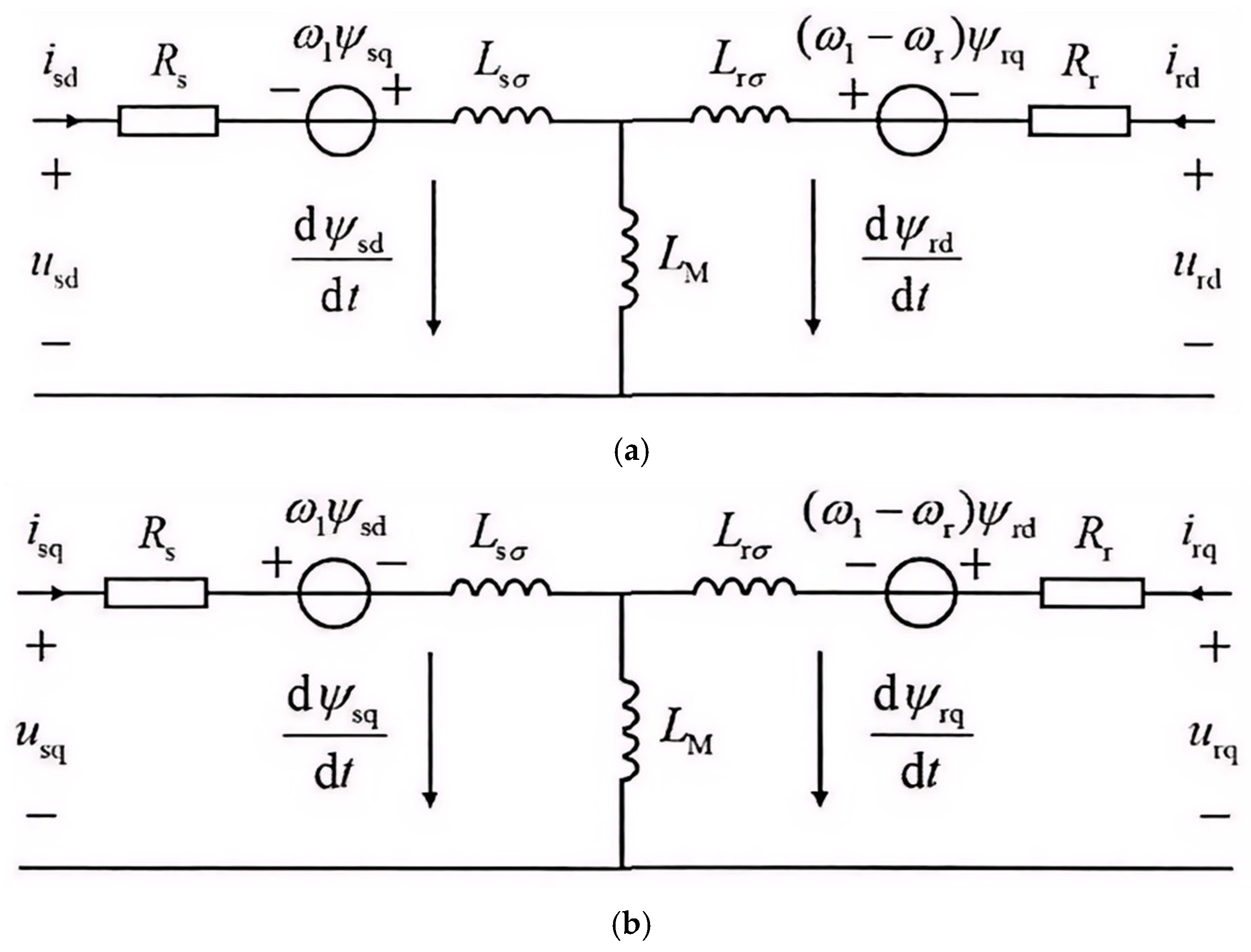
First, the equivalent circuit diagram of the doubly fed induction motor in the dq-axis is drawn, and further analysis is performed based on the circuit diagram.
Based on the dq-axis equivalent circuit model of the DFIG shown in
Figure 2, the spatial vector equations for the stator and rotor voltages are first written according to Kirchhoff’s voltage law (KVL). At this time, the voltage and current are complex vectors containing amplitude and phase information. There is a phase difference between the resistive voltage drop and the induced electromotive force generated by the inductance, and their relationship is expressed [
25] as follows:
where
u,
i, and
ψ represent the spatial vectors of voltage, current, and magnetic flux, respectively;
j is the imaginary unit vector, reflecting the phase relationship between the rotating electromotive force and the main magnetic flux in the rotating coordinate system. Decomposing the above vector equations in the synchronously rotating coordinate system, letting the real part be the d-axis component and the imaginary part be the q-axis component, the instantaneous voltage equations in the dq coordinate system can be obtained as follows:
In the formula, usd, usq, urd, urq are the stator and rotor voltages in dq coordinates. The voltage and current components here are instantaneous components. ψsd, ψsq, ψrd, ψrq are the stator and rotor flux in dq coordinates; Rs and Rr are the stator resistance and rotor resistance. In addition, ωs is the synchronous angular velocity, and ωr is the rotor angular velocity, so ωs − ωr is the slip angular velocity.
Based on the equivalent circuit shown in
Figure 2, and considering the magnetic coupling effect between the stator and rotor windings, the magnetic flux linkage equations can be expressed as follows:
In the formula, Ls and Lr, respectively, represent the stator inductance and rotor inductance of the motor.
Combining Formulas (5) and (6) and simplifying them, the differential expression of the stator and rotor current of the DFIG with respect to time is as follows:
For the denominator part of the above formula, we have , .
2.3. Converter Model
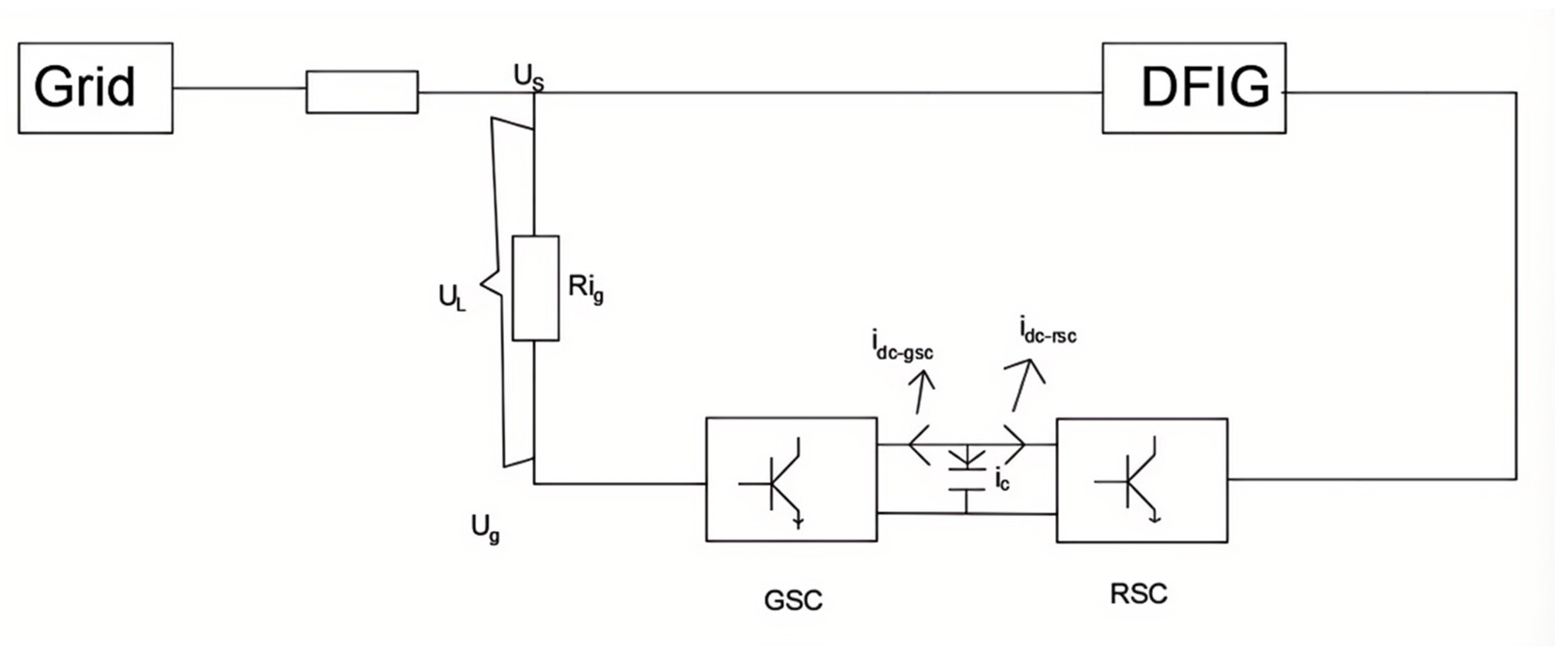
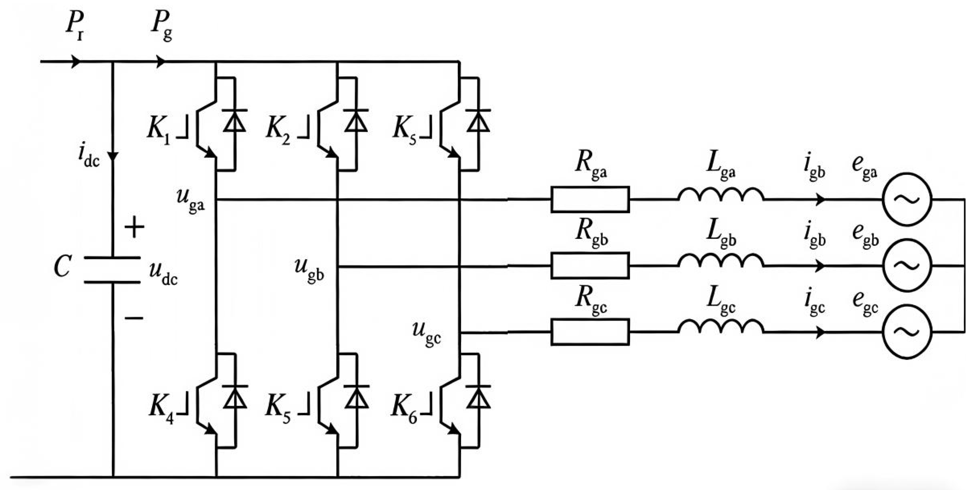
In a DFIG setup, the rotor winding couples to the grid via a back-to-back PWM converter system, which consists of the RSC and the GSC. Both can operate in rectification or inversion mode. A DC capacitor connects the two converters, allowing for independent control of the RSC and GSC to meet multi-objective control requirements. Since the circuit structures of the RSC and GSC are identical, the mathematical model of the converter is introduced using the GSC as an example. The circuit structure of the grid-side converter is shown in the figure below. The switching state equations of the rotor-side converter can be derived. It should be noted that
Figure 3 mainly shows the topology of the converter connected to the grid via a filter inductor. This part of the circuit mainly reflects the filtering and transmission characteristics of the inductor and does not involve the stator–rotor magnetic coupling relationship inside the generator itself. Based on this, applying voltage and current laws, combined with energy conservation, and using the fourth-order Runge–Kutta method for iteration, the control model for model predictive control can be obtained.
The switching state of the converter is determined by the gate signals K
1, K
2, and K
3 [
26] (K
4, K
5, and K
6 are opposite to the switching states of K
1, K
2, and K
3, respectively). These signals can be expressed in vector form as follows:
where
, and therefore, the output voltage space vector of the converter is defined by the following formula:
where
uga,
ugb, and
ugc are the three-phase voltage values output by the converter. Accordingly, a direct correlation exists between the output voltage vector, the switching vector, and the DC voltage
udc, where the switching states are described by the following:
where
ui can represent the output voltage of either the grid-side converter or the machine-side converter, and
Si can represent the switching state of either the GSC or the RSC. Therefore, the formulas for the output voltages of the GSC and RSC are as follows:
where
vr and
vg are the output voltages of the RSC and the GSC, respectively, and
Kr and
Kg are the switch state vectors of the RSC and the GSC, respectively.
The grid-side current
ig is composed of the inductor d-axis current
iLd and the inductor q-axis current
iLq, and its expression is as follows:
Combined with the above analysis, the voltage and current diagram of the doubly fed induction generator converter part is shown in
Figure 4 below:
As shown in
Figure 4, the grid-side converter is connected to the power grid through a filter inductor. To accurately describe the dynamic relationship between the AC-side voltage and current, and to represent the phase shift between the vectors, a complex space vector model needs to be established in the synchronous rotating coordinate system (dq coordinate system).
According to KVL, the complex vector form of the voltage balance equation for the grid-side circuit can be expressed as follows:
where
us,
ig are the grid voltage vector and grid-side current vector;
Rg and
Lg are the equivalent resistance and inductance values of the grid-side filter inductor. In the above equation, the introduction of the imaginary term reflects the orthogonal phase relationship between the inductor voltage and current in the rotating coordinate system.
Decomposing the above complex vector equation into d-axis and imaginary q-axis components, the state equations of the grid-side converter in the dq coordinate system can be obtained as follows:
From
Figure 4, KCL is applied to the DC side of the converter, and we obtain the following:
where
iC is the current flowing through the capacitor on the DC side;
idc-gsc and
idc-rsc are the DC currents of the GSC and the RSC, respectively. The calculation formula obtained by power conservation is as follows:
where
and
represent the conjugate values of the DC currents of the RSC and the GSC, respectively.
From the capacitor calculation formula
and the inductor calculation formula
, the differential of the state variable can be expressed by the following formula:
where
Re(
uL) and
Im(
uL) are the real and imaginary parts of the inductor voltage, respectively.
2.4. Crowbar Circuit Model
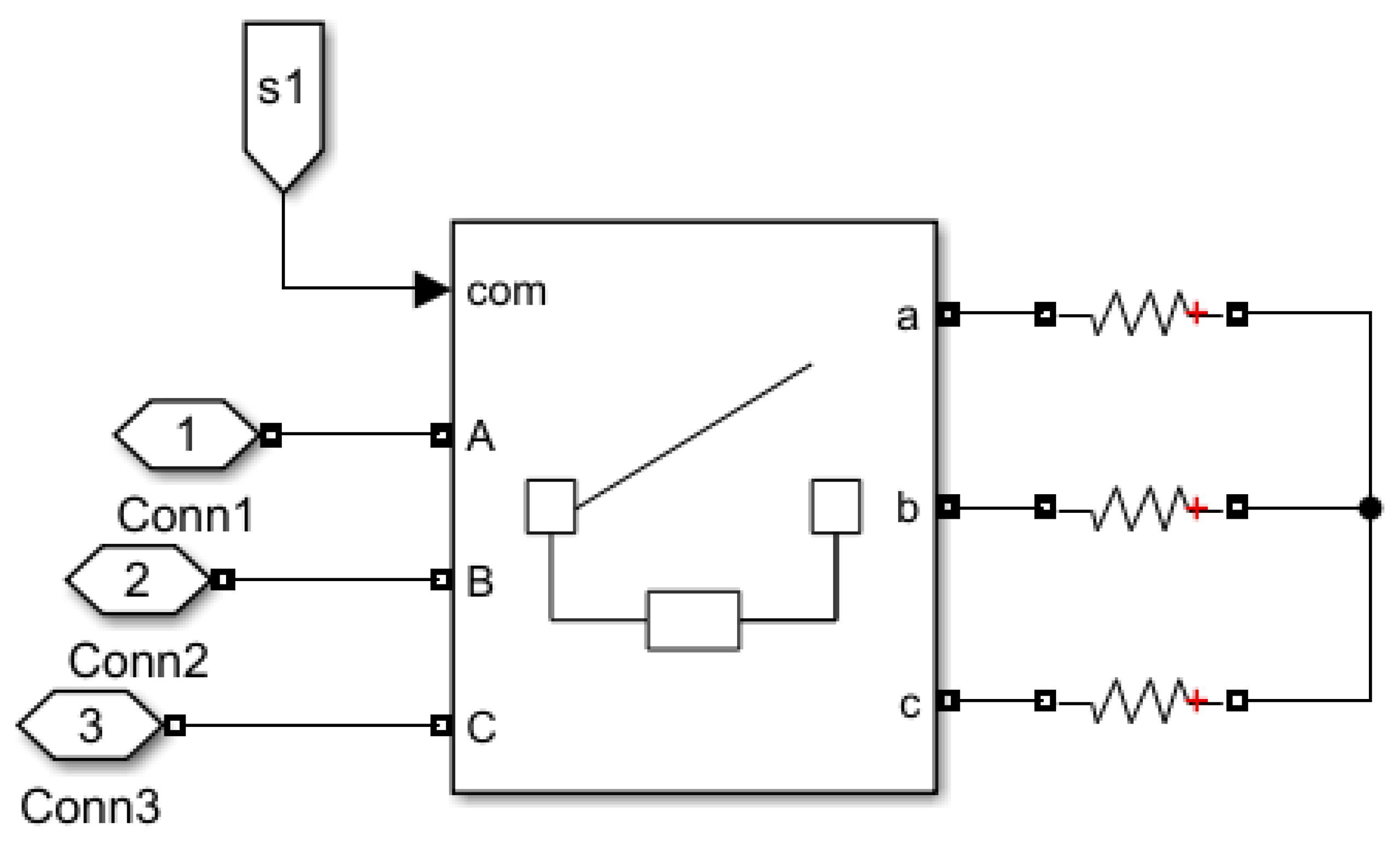
The crowbar protection circuit has a simple structure and reliable control. It is the most commonly used rotor winding hardware protection circuit. The crowbar circuit is a set of parallel branches located after the rotor winding outlet and before the RSC. When the rotor winding has over current or over voltage, the power electronic components within the branch are activated to establish a bypass channel for the current flow. This paper uses an active crowbar protection circuit, which can cut off the crowbar circuit from the rotor circuit at any time during the operation, so that the RSC can be restored to normal working state. The structure diagram of the crowbar circuit used is shown in
Figure 5 below:
As shown in the figure, the three-phase crowbar circuit is controlled by a circuit breaker, and the resistance of each phase crowbar circuit is equal. By controlling the circuit breaker, the time of crowbar input and removal can be flexibly controlled, so that the crowbar circuit can be put into operation at the same time when a fault occurs, thereby significantly mitigating the adverse influence of grid disturbances on the circuitry.
3. LVRT Control Strategy Based on MP-CC
3.1. Principle of MPC
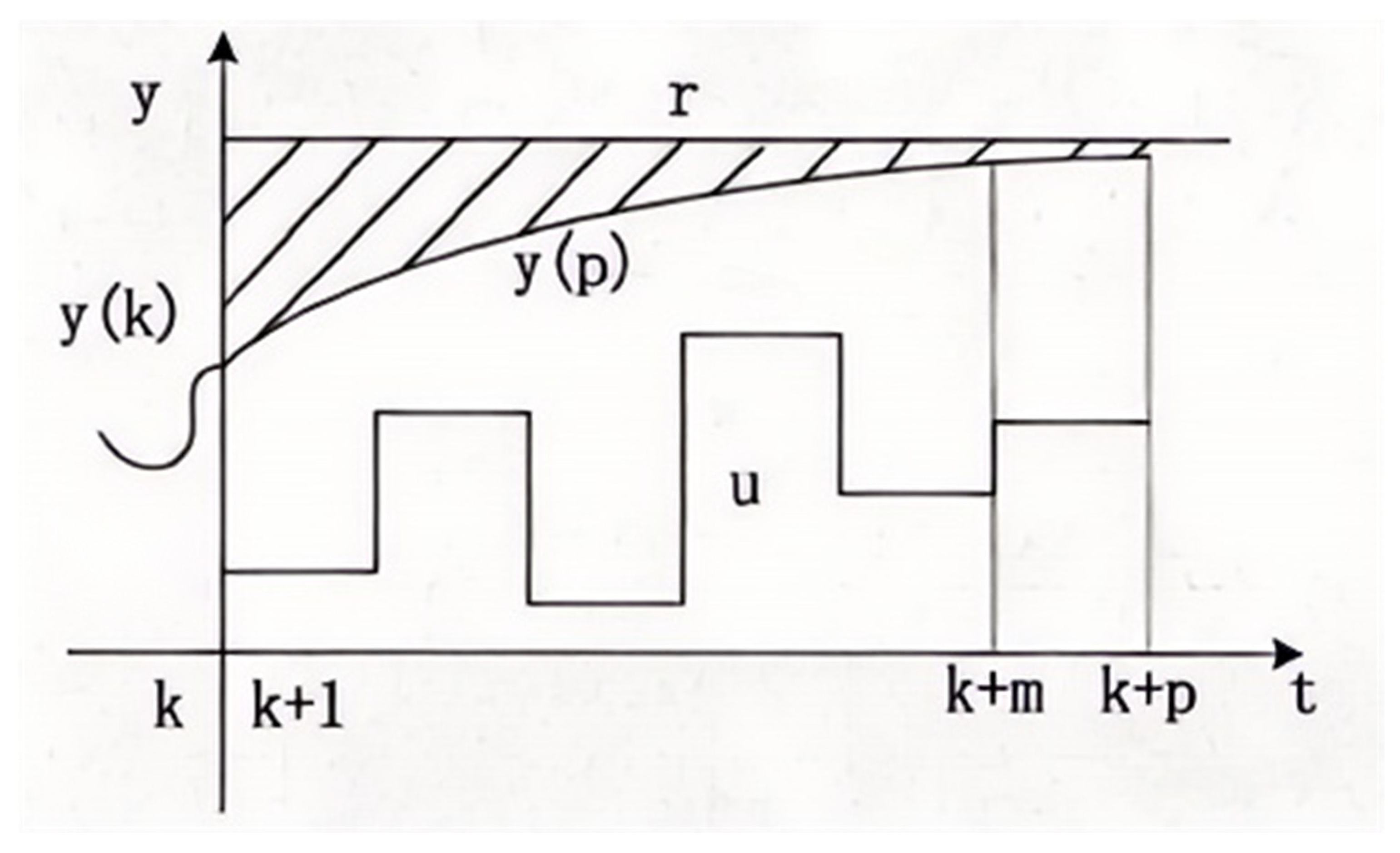
MPC is a control technology based on the system dynamic model. MPC predicts the system behavior for a period of time in the future based on the model at the current moment and then determines the control input by solving an optimization problem. The goal of the optimization problem is to minimize the cost function. In MPC, the optimization problem is usually solved within a limited prediction time horizon. Each time the MPC is calculated, it will re-solve the optimization problem based on the current state and only execute the first control input in the optimization result. Then it will move on to the next moment and repeat this process. This process is called rolling horizon optimization. In general, the predictive control algorithm includes three steps:
Predict the future dynamics of the system. Given the system measurement value y(k), predict the output of the system from y(k) to a period of time in the future, denoted as y(k + p), where p is the prediction time domain. The control input in the prediction time domain is denoted as u(k), and the control target is the system output r, where r is the expected output.
The optimization problem is solved numerically. At every sampling instance, the problem formulation is updated with the most recent measurements and resolved. Subsequently, the first element u(k1) of the resulting optimal control sequence is applied to the system.
Repeat the above process at time k + 1. Repeat the optimization process until the constraints meet the requirements.
The principle diagram of MPC is shown in
Figure 6 below:
3.2. Runge–Kutta Method
The Runge–Kutta method is a high-precision algorithm widely used by engineers for numerically solving differential equations. Among them, the fourth-order Runge–kutta method (RK4) is the most commonly used method in the computer simulation solution process and has significant advantages in the simulation process. The MP-CC control used in this paper uses the RK4 method for convergence. When using the RK4 method, the initial value problem can be expressed as follows:
Then, the RK4 equation for this problem is given by the following equation:
where
,
yn is the function value of the current step,
yn+1 is the approximate solution of the next step, and
k1–
k4 are the slopes at different positions.
3.3. MP-CC LVRT Control Model
This program implements a cooperative control strategy for a DFIG based on Finite control set model predictive control (FCS-MPC). The core idea of the algorithm is to utilize the discrete switching characteristics of the converter to construct a finite control set containing eight basic voltage vectors. First, eight different switching combinations of the three-channel converter are listed, where Sr and Sg represent the eight different combinations of the stator and rotor converters, respectively. Through state transition equations, the power and accumulated error at the current time are calculated, and the switching state with the minimum error is selected. The Runge–Kutta method is used for real-time error control. The program adopts a collaborative optimization architecture for the grid-side converter and the rotor-side converter. Through a double nested loop structure, all 64 global switching combinations are traversed and searched in each control cycle. For each combination, the algorithm uses the RK4 to solve the state equations and predict the system state in the next n steps. Compared with the traditional Euler method, RK4 can significantly reduce the prediction error caused by discretization.
The error of the input initial state is as follows:
The state space of the DFIG is linearized to obtain the linearized state space expression of the DFIG:
Here, A, B, C, and D are all coefficient matrices, and the objective function is defined as minimizing the difference between the active and reactive power and their reference values:
The initial state is set with n = 0. The target formula is then used for calculation. If the calculated cumulative error is greater than the minimum error, the calculation continues for the next value. If the calculated cumulative error is less than the minimum error, the value of the cumulative error is saved, along with the switching states of the grid-side and machine-side converters obtained during this process. Then, in this state, the 3-channel converter is transformed into a 6-channel converter, ensuring that the two switches in the same branch have opposite states during the conversion process, and then the signal is output. Finally, the algorithm outputs the optimal switching state combination that minimizes the cost function, and converts it into a 6-channel pulse signal to drive the converter, and then calculates the resulting active and reactive power values.
In the above equation,
ugd and
ugq represent the d-axis and q-axis components of the grid voltage, and the following applies for
id and
iq:
isd and isq are the d-axis and q-axis components of the stator current, and iLd and iLq are the d-axis and q-axis components of the grid-side converter current.
3.4. Algorithm Complexity and Real-Time Performance Analysis
The MP-CC strategy proposed in this paper employs coordinated control of the grid-side and machine-side converters, requiring the traversal of 64 switching combinations within a single control cycle. Furthermore, to improve prediction accuracy, the model discretization uses the RK4. Compared to traditional PI control or Euler-based MPC, the computational burden is indeed increased. However, for the practical application scenario of megawatt-level doubly fed wind turbines, the algorithm is real-time feasible, as analyzed below:
Algorithm Complexity Quantification: For 64 switching combinations, the controller needs to complete 64 model predictions and cost function calculations within one cycle. Since this algorithm belongs to FCS-MPC, its optimization process is exhaustive traversal, requiring no complex differential iteration or quadratic programming solutions. Therefore, the algorithm’s execution time is deterministic, and there are no convergence issues.
Hardware Execution Capability:
DSP Platform: Modern multi-core DSPs commonly used in wind turbine main controllers (such as the 2837x series) have clock speeds up to several hundred MHz. For high-power doubly fed wind turbines of 3 MW and above, the control cycle is approximately 400–500 microseconds. Within such a long control cycle, modern DSPs are fully capable of serially completing 64 algebraic operation cycles.
FPGA Platform: If an FPGA (such as Xilinx Kintex-7) is used, its parallel processing capabilities can be utilized to distribute the prediction process of the 64 switching combinations to different logic units for parallel execution. In this case, the total time required for the algorithm will only depend on the time of a single RK4 prediction, and the calculation delay can be reduced to the microsecond level, fully meeting real-time requirements.
In summary, although the computational load of the strategy presented in this paper is greater than traditional methods, it is fully feasible for real-time operation within the computing power of current mainstream industrial control chips.
4. Simulation Analysis
4.1. Parameter Settings
This paper uses MATLAB/Simulink (version 2024b) software to build a DFIG model and conduct simulation verification. The fault scenarios are categorized into two types: one is a general fault, where the voltage is reduced to 50% of the nominal voltage, and the other is a severe fault, where the voltage drops to 20% of the nominal voltage. The power grid system is set to experience a voltage drop at 1 s, the fault duration is 0.5 s, and the fault is restored at 1.5 s. To validate the enhanced efficacy of the MP-CC strategy combined with a crowbar circuit in boosting DFIG low-voltage ride-through resilience, this study conducts a comparative analysis against PI and MP-CC methods. Simulations are configured for a duration of 2.5 s utilizing the ode23 solver, with a step interval 5 × 10⁻⁶ s.
The main parameter table (
Table 1) of the DFIG is as follows:
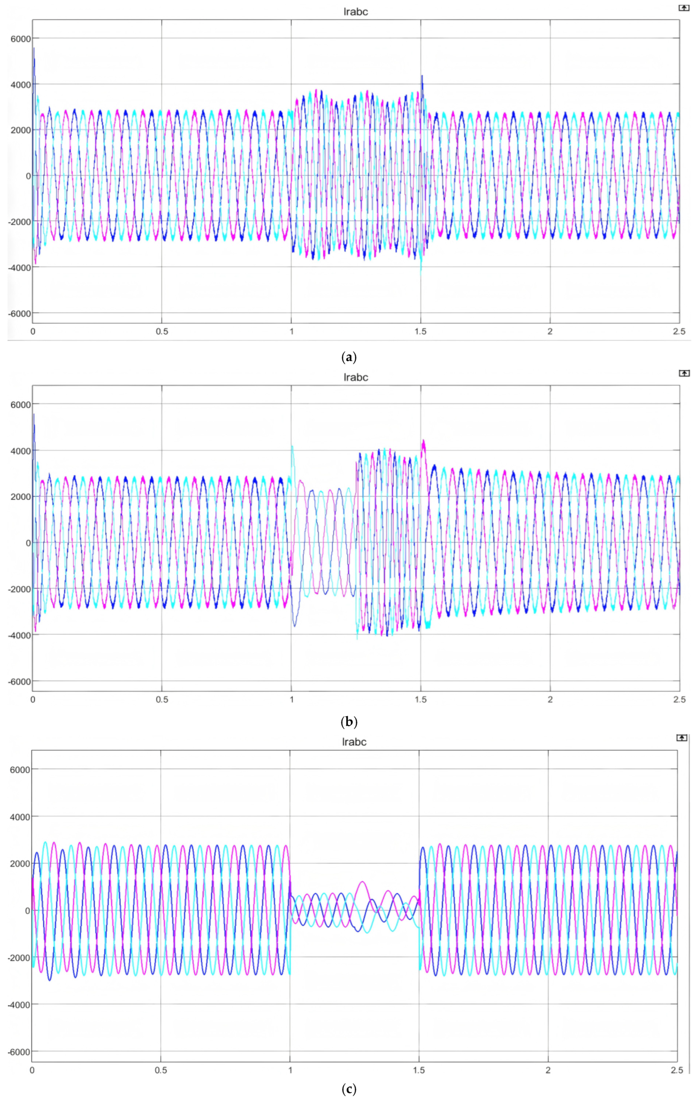
The main parameters of the DFIG discussed in this paper are engine terminal current, rotor-side current, reactive power, electromagnetic torque, and DC voltage.
Machine-end current: When the grid voltage suddenly drops, the stator flux cannot change instantaneously, which will cause the machine-end current of the DFIG to increase. This current will affect the entire system, pose a threat to the safety of the stator side, and affect the stability of the entire system.
Rotor-side current: During a voltage drop, the rotor current may rise abnormally, potentially exceeding the converter’s current limit and causing hardware failure. Therefore, once the current exceeds the set limit, effective mitigation measures must be taken immediately; otherwise, it may disrupt the stability of the entire power grid.
Reactive Power: This term specifically denotes the reactive power measured at the DFIG stator terminals. Upon activation of the crowbar protection mechanism, the RSC is effectively blocked. Consequently, the DFIG is forced to draw reactive power from the grid to maintain excitation, a behavior that hinders the voltage recovery process during faults.
Electromagnetic torque: When the grid voltage drops, the stator flux cannot change suddenly due to the transient component, which will cause air gap magnetic field distortion and cause violent fluctuations in the electromagnetic torque. Violent fluctuations in the electromagnetic torque will have an adverse effect on the wind turbine system, causing mechanical fatigue and even structural damage, so it is also very important to control the electromagnetic torque during the LVRT process.
DC voltage: When the voltage drops, the stator-induced electromotive force transmits energy back to the DC bus through the converter. During this interval, the DC voltage risks surging beyond the converter’s rated limits. Such a voltage spike poses a threat to the DC capacitors; therefore, implementing robust measures to suppress the DC-link voltage rise is mandatory.
Among the three different control methods adopted in this paper, one method uses only the control strategy for protection, while the other two methods combine the control strategy with the crowbar circuit for protection. It should be noted that, in the simulation setup, in order to focus on evaluating the effectiveness of the coordinated control logic between the MP-CC and the crowbar circuit in improving system stability, the crowbar circuit was idealized and modeled as an ideal switch with no switching delay. Although in practical engineering, the triggering of the crowbar is limited by the detection threshold and the switching device’s operating time (typically in the millisecond range), considering that the time scale of the low-voltage ride-through process studied in this paper is relatively long (in seconds), and that modern active crowbar circuits have very fast response speeds, neglecting its small operating delay has little impact on verifying the overall effectiveness of the control strategy proposed in this paper. Therefore, in both control methods using crowbar circuits described in this paper, the crowbar circuit breaker control switch is treated as ideal, that is, at the moment of the fault, the crowbar circuit is immediately put into operation, ignoring the action delay of the crowbar protection, and the total time of the crowbar is 0.25 s, that is, the crowbar circuit is put into operation at t = 1 s, and the crowbar circuit is cut off at t = 1.25 s. The resistance value of the crowbar circuit used is 0.2 pu.
4.2. Simulation Analysis of LVRT of DFIG When the Grid Voltage Drops to 50%
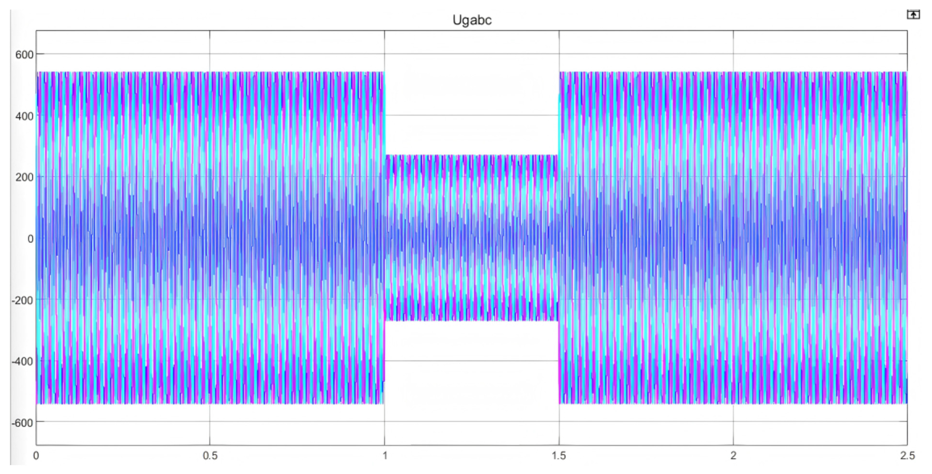
In the initial state, the grid line voltage is set to 690 V, and we have the following:
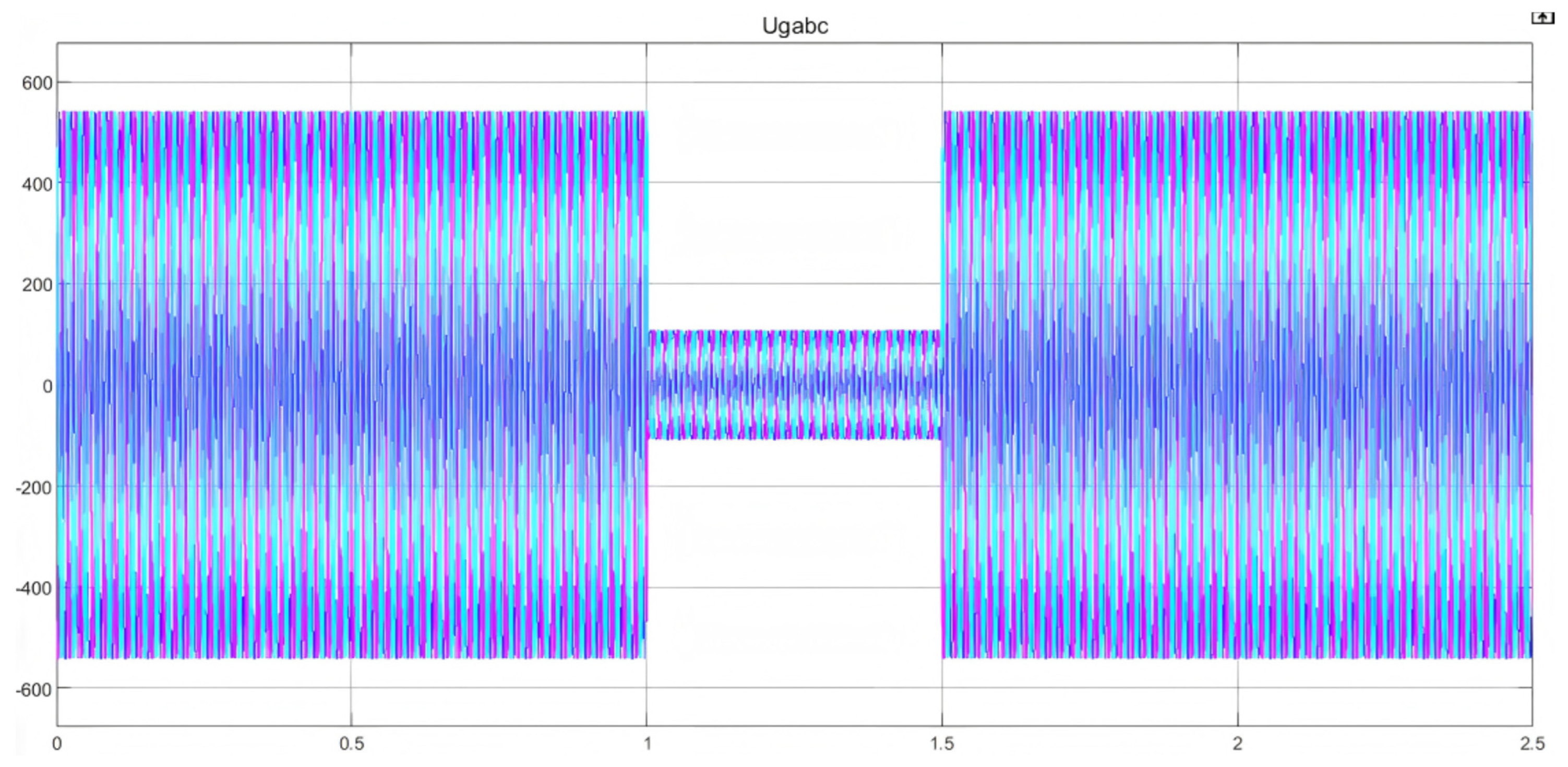
In the formula, VPG is the relative voltage of the grid to the ground, and 1.04 is the loss coefficient of the voltage transmission in the line. The waveform diagram of the grid voltage when the grid voltage drops by 50% is shown in
Figure 7. By comparing the data obtained by the above formula with the simulation waveform, it can be seen that the data of the initial voltage obtained by the above formula are exactly the same as the waveform data. Under normal fault conditions, when the grid voltage drops to 50%, the grid waveform is shown in the figure below. The specific voltage drop process can also be seen from the waveform.
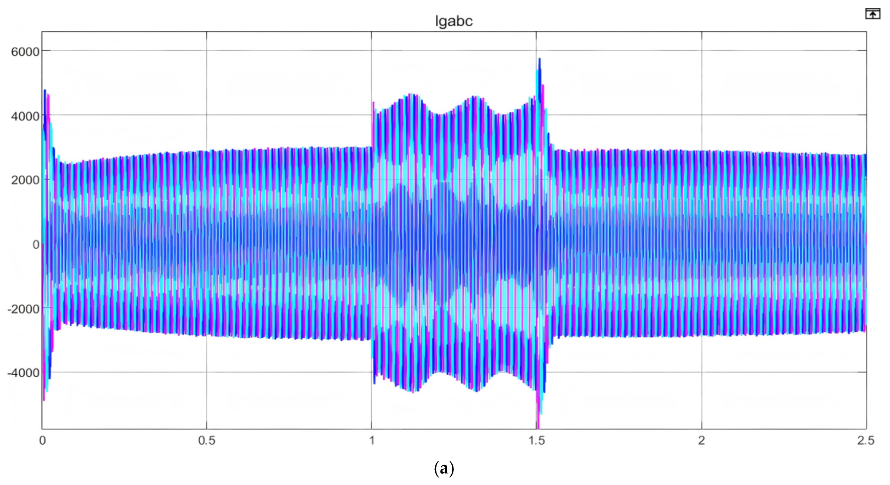
Figure 8 shows the waveform of the machine-end current of the DFIG under three different control modes: PI, PI+Crowbar, and MP-CC+Crowbar, when the grid voltage drops to 50%. Three different control methods are used for analysis to verify the superiority of the MP-CC+Crowbar control method proposed in this paper in the LVRT process. From the waveform, it can be observed that when the crowbar circuit is not used, the stability of the machine-end current is poor under the effect of PI control alone. When the grid voltage drops, the machine-end current increases significantly, which will affect the stability of the DFIG. When PI+Crowbar is used for control, the control effect of the machine-end current when the voltage drops are significantly better than that of using only the crowbar, and the increase in the machine-end current is significantly reduced. When MP-CC+Crowbar is controlled, when the grid voltage drops, the machine-end current does not increase significantly, thereby ensuring that the DFIG has a certain LVRT capability.
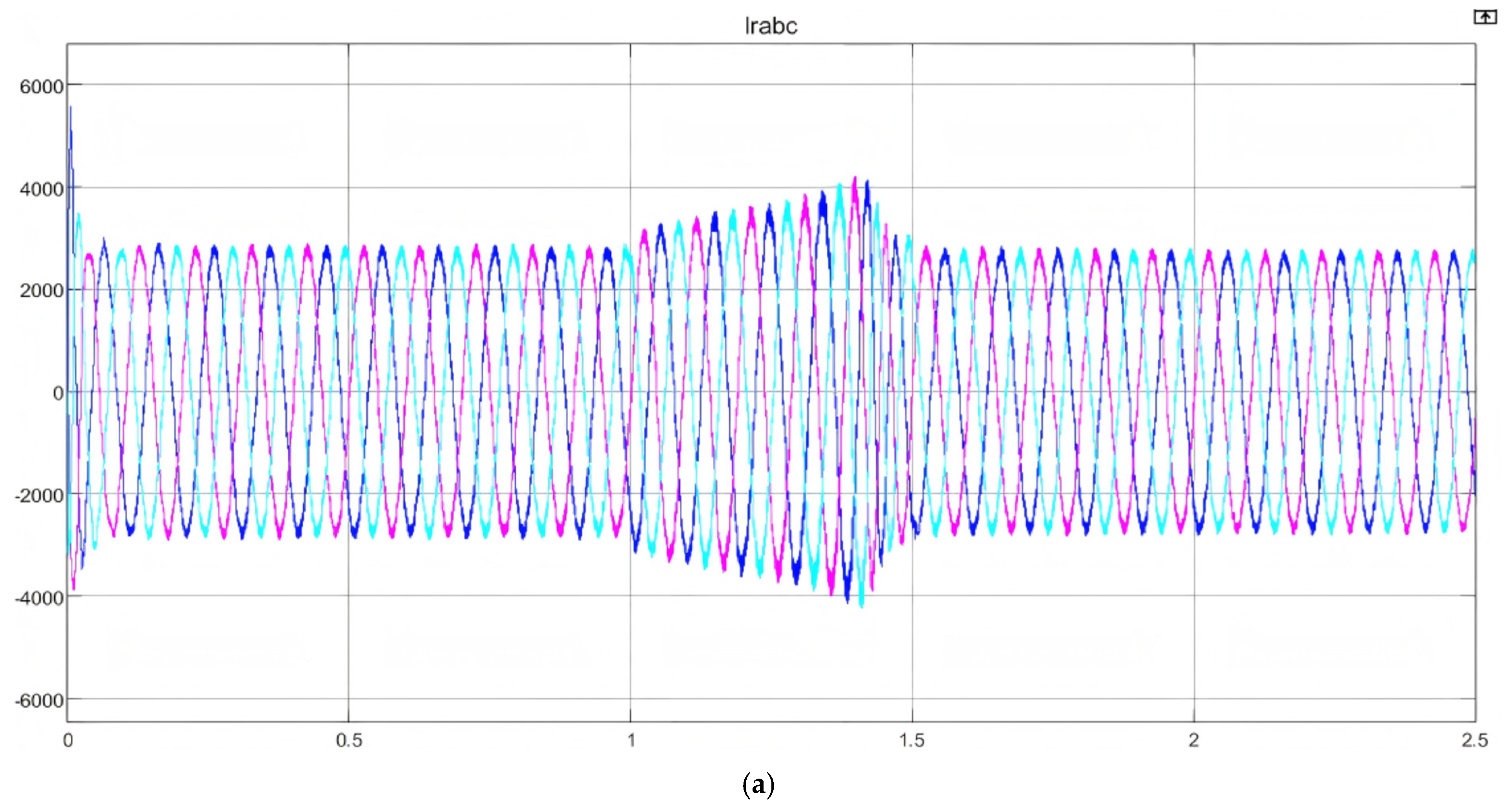
Figure 9 shows the rotor-side current waveform of the DFIG under three different control modes, PI, PI+Crowbar, and MP-CC+Crowbar, when the grid voltage drops to 50%. As can be seen from the figure, under the control effects of PI and PI+Crowbar, the rotor-side current increases to a certain extent, which is not conducive to the smooth LVRT of the DFIG. However, with MP-CC+Crowbar control, the rotor current does not increase significantly during the voltage drop, which effectively improves the LVRT capability of the DFIG.
Based on the analysis above, the peak values of the machine-side current waveforms and rotor-side current waveforms under three different control scenarios are summarized in
Table 2. This table demonstrates the superiority of MP-CC control during low-voltage ride-through.
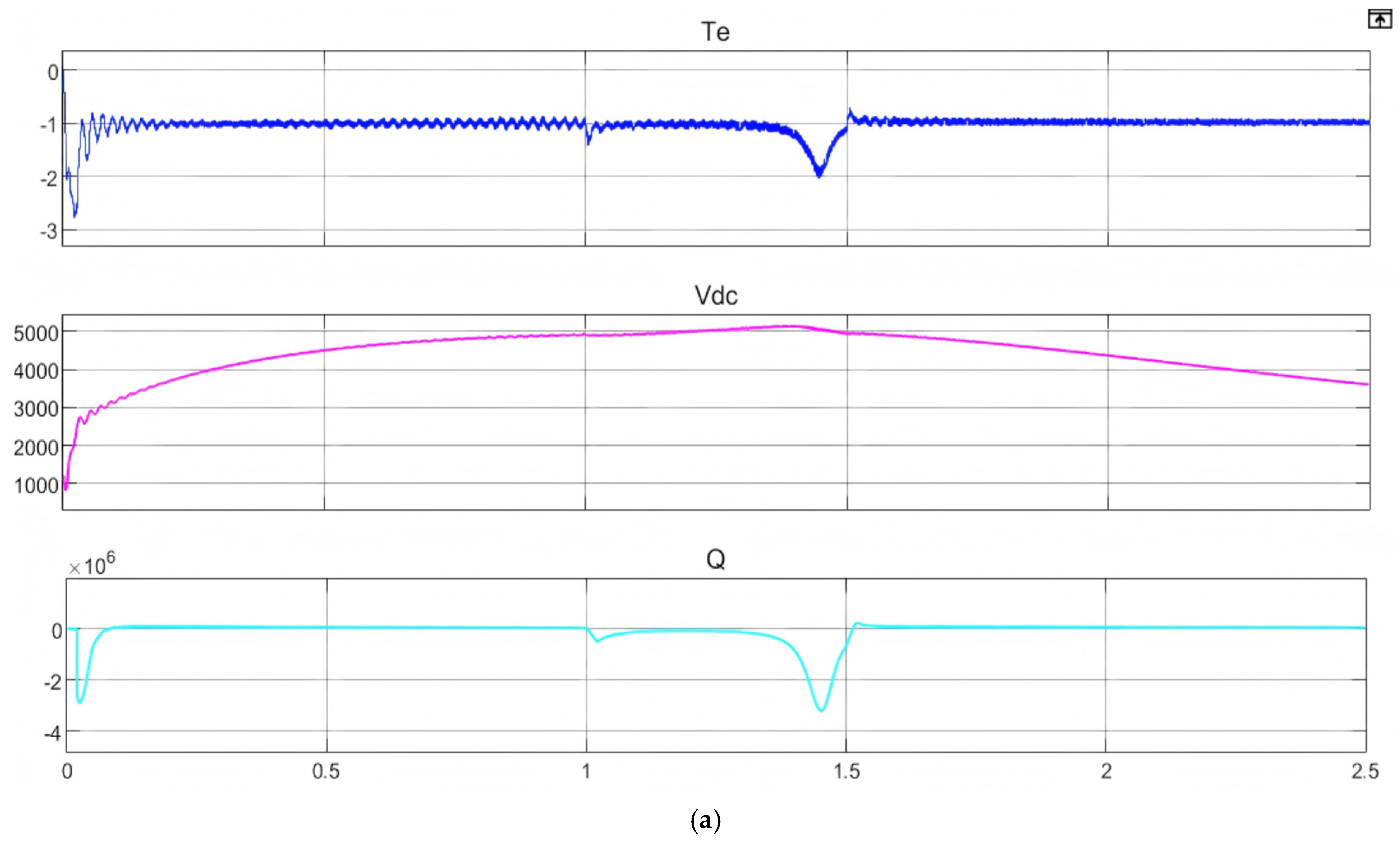
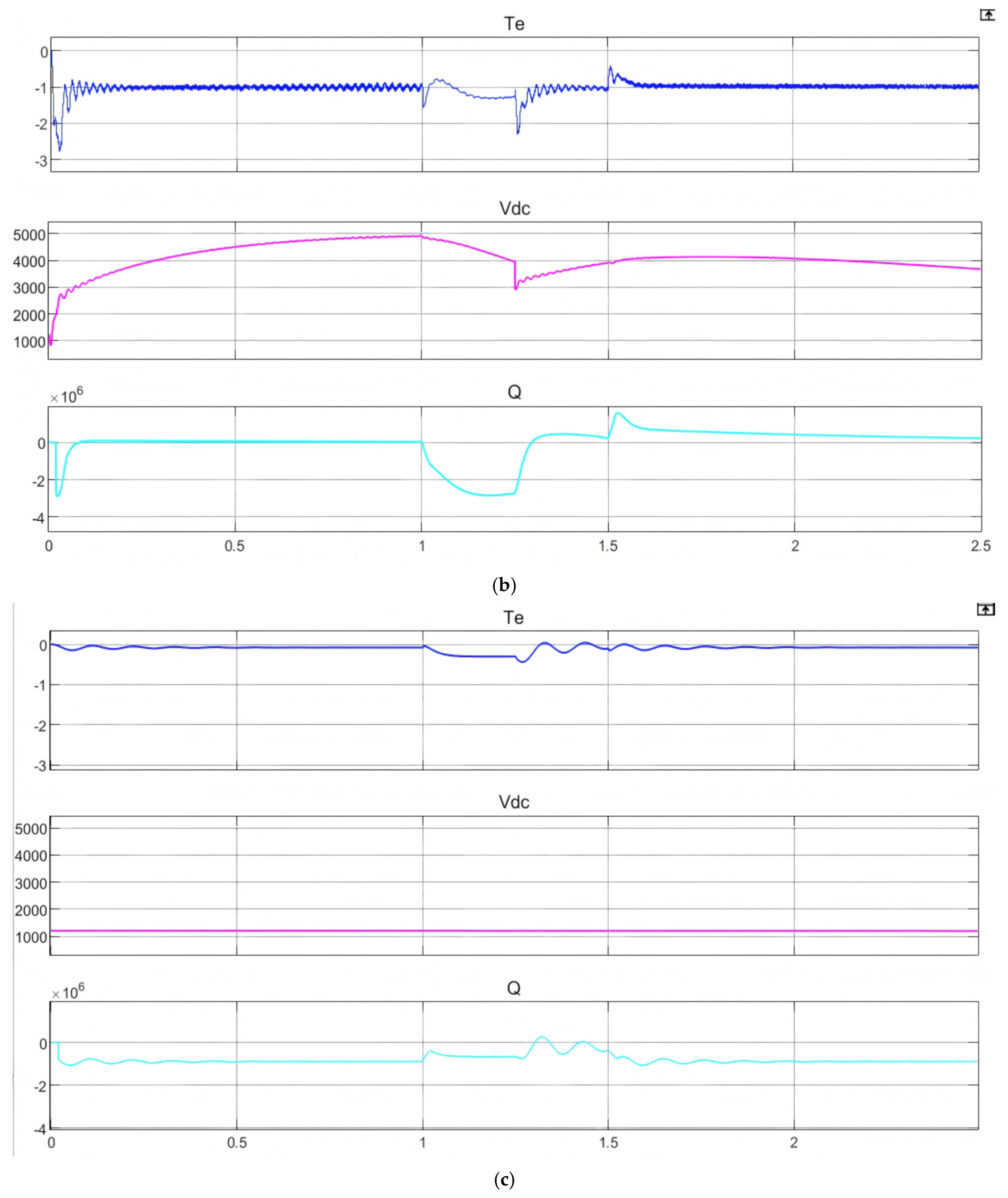
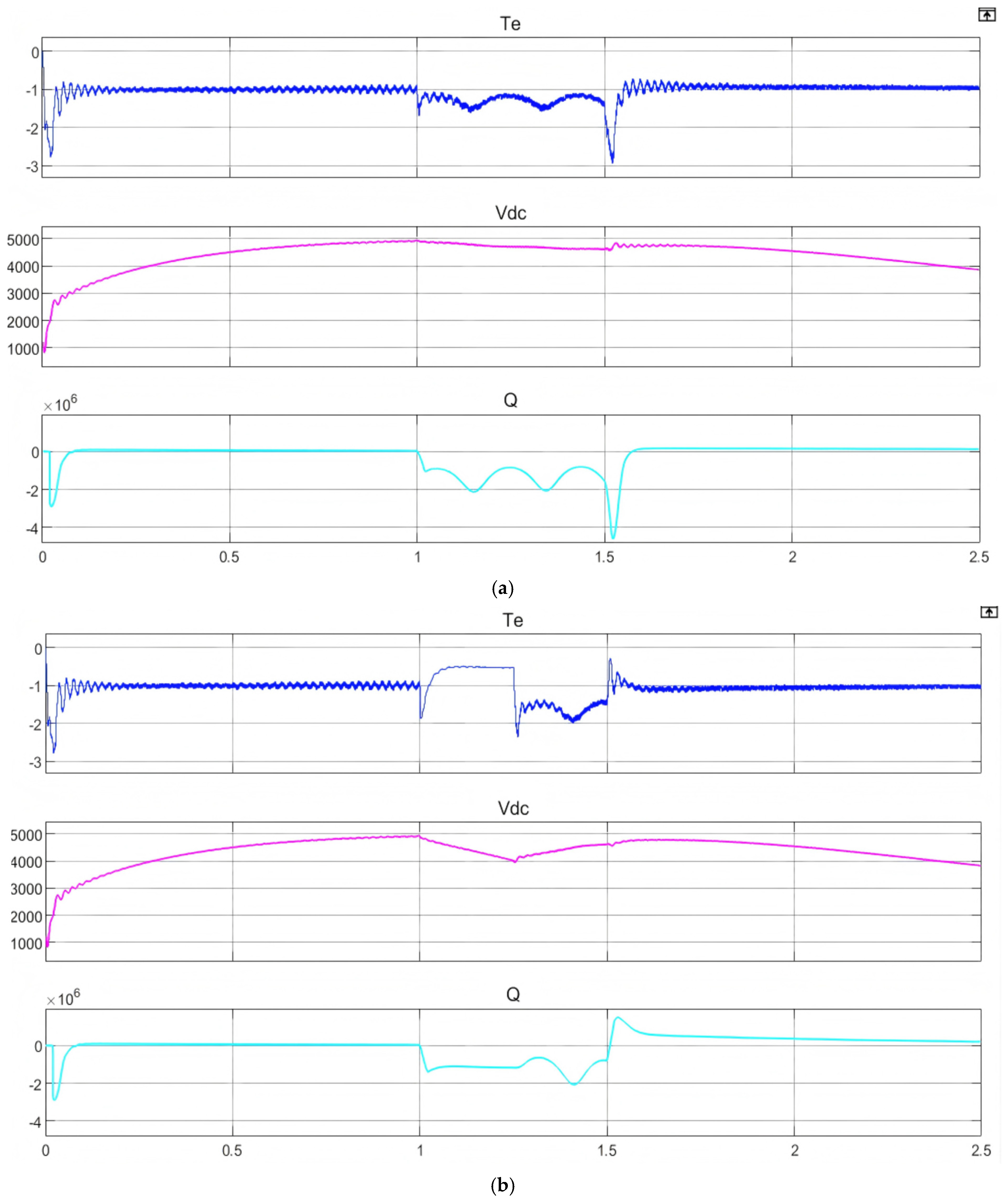
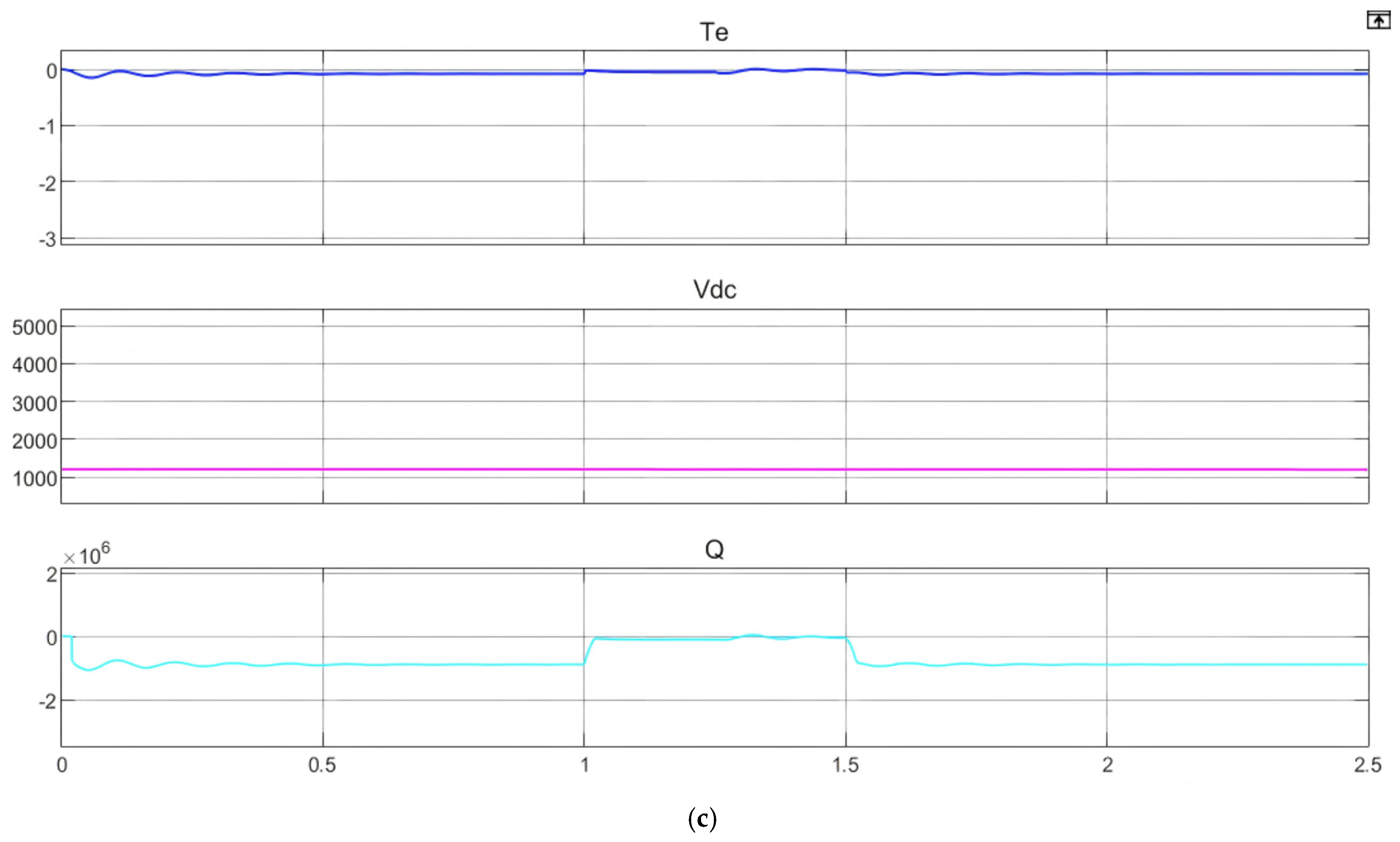
Figure 10 shows the electromagnetic torque, DC voltage, and reactive power waveforms of the DFIG under three different control modes, PI, PI+Crowbar, and MP-CC+Crowbar, when the grid voltage drops to 50%. It can be seen from the waveform that under the PI control mode and the PI+Crowbar control mode, the electromagnetic torque fluctuates to a certain extent; especially when the grid voltage drops, the electromagnetic torque fluctuates more violently. When the MP-CC+Crowbar control strategy is used, the electromagnetic torque fluctuates the least, and it basically remains stable during the grid voltage drop, and the stability under the voltage drop fault is higher. Therefore, the use of the MP-CC+Crowbar control strategy can effectively reduce the fluctuation amplitude of the electromagnetic torque and improve the stability of the DFIG during LVRT.
The waveform diagrams show that the DC bus voltage fluctuates significantly throughout the process when using both PI control and PI+Crowbar control methods, quickly rising to over 5000 V. However, when using the MP-CC+Crowbar control strategy, the DC bus voltage fluctuations are minimal, remaining consistently around 1200 V throughout the entire process, effectively protecting the DC bus voltage safety.
Once the crowbar is engaged and the RSC is blocked, the DFIG draws reactive power from the grid to maintain excitation. This process inevitably worsens the voltage sag and hinders recovery. However, waveform analysis highlights that the MP-CC+Crowbar strategy—in contrast to the PI+Crowbar method—significantly suppresses this reactive power absorption during faults, thereby actively supporting grid voltage restoration.
4.3. Simulation Analysis of LVRT of DFIG When the Grid Voltage Drops to 20%
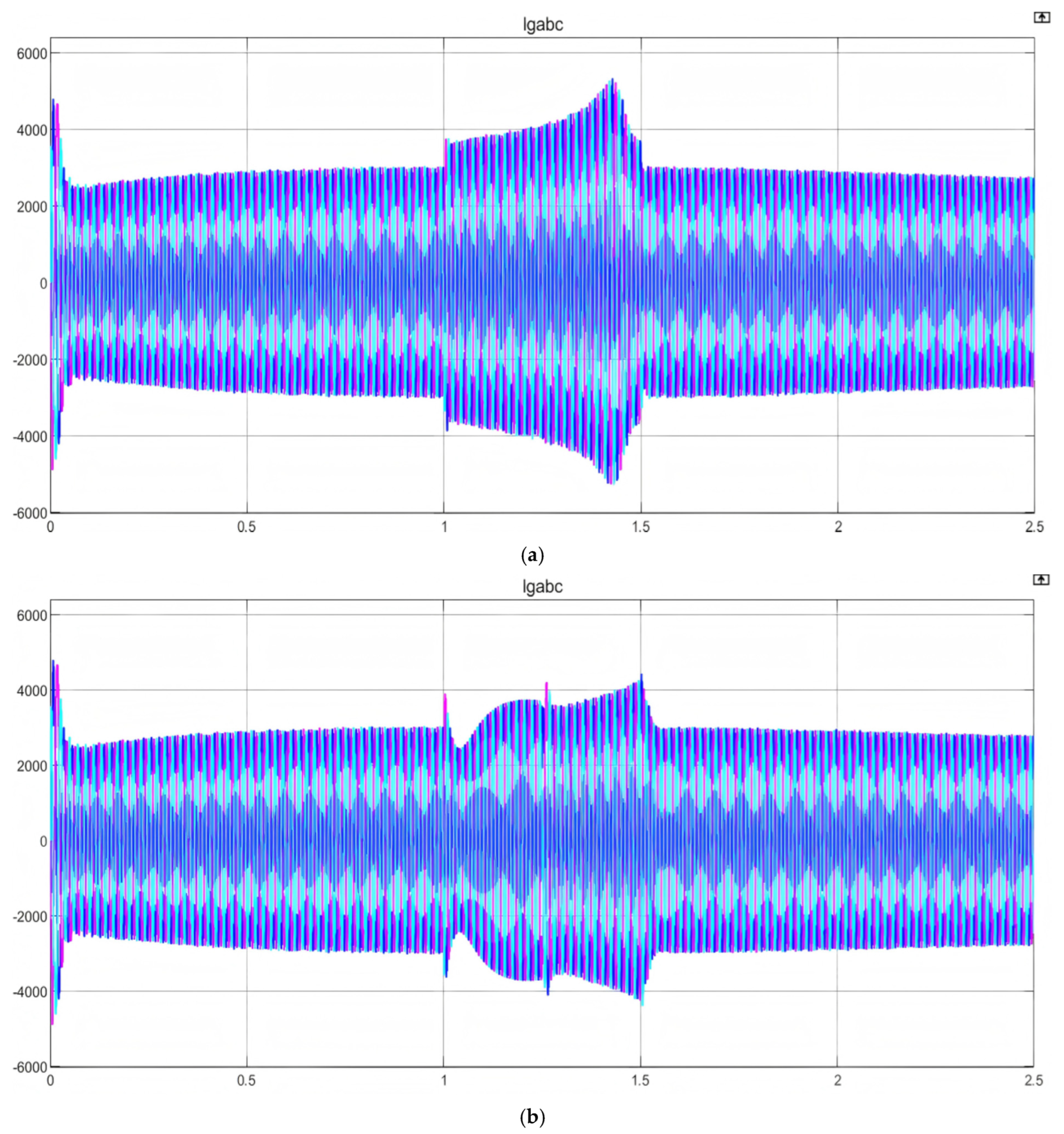
In the case of a serious fault, the grid waveform when the grid voltage drops to 20% is shown in
Figure 11 below. The specific voltage drop process can also be seen from the waveform diagram. As shown in the figure, at t = 1, the voltage drops significantly. Compared with the voltage drop fault in the previous part, this fault is obviously more serious. The parameters of the drop process are analyzed for this fault.
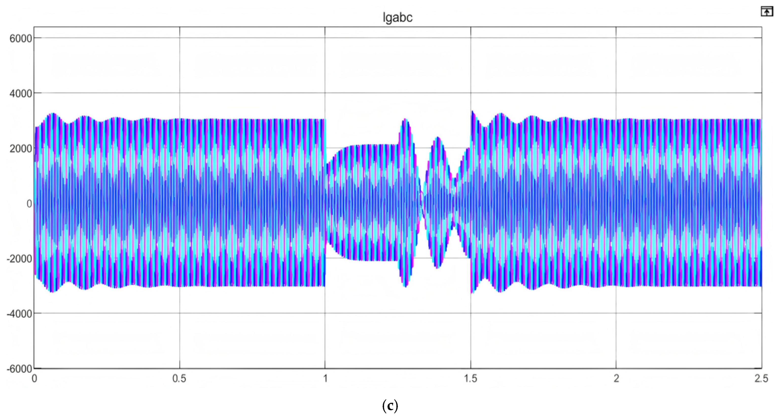
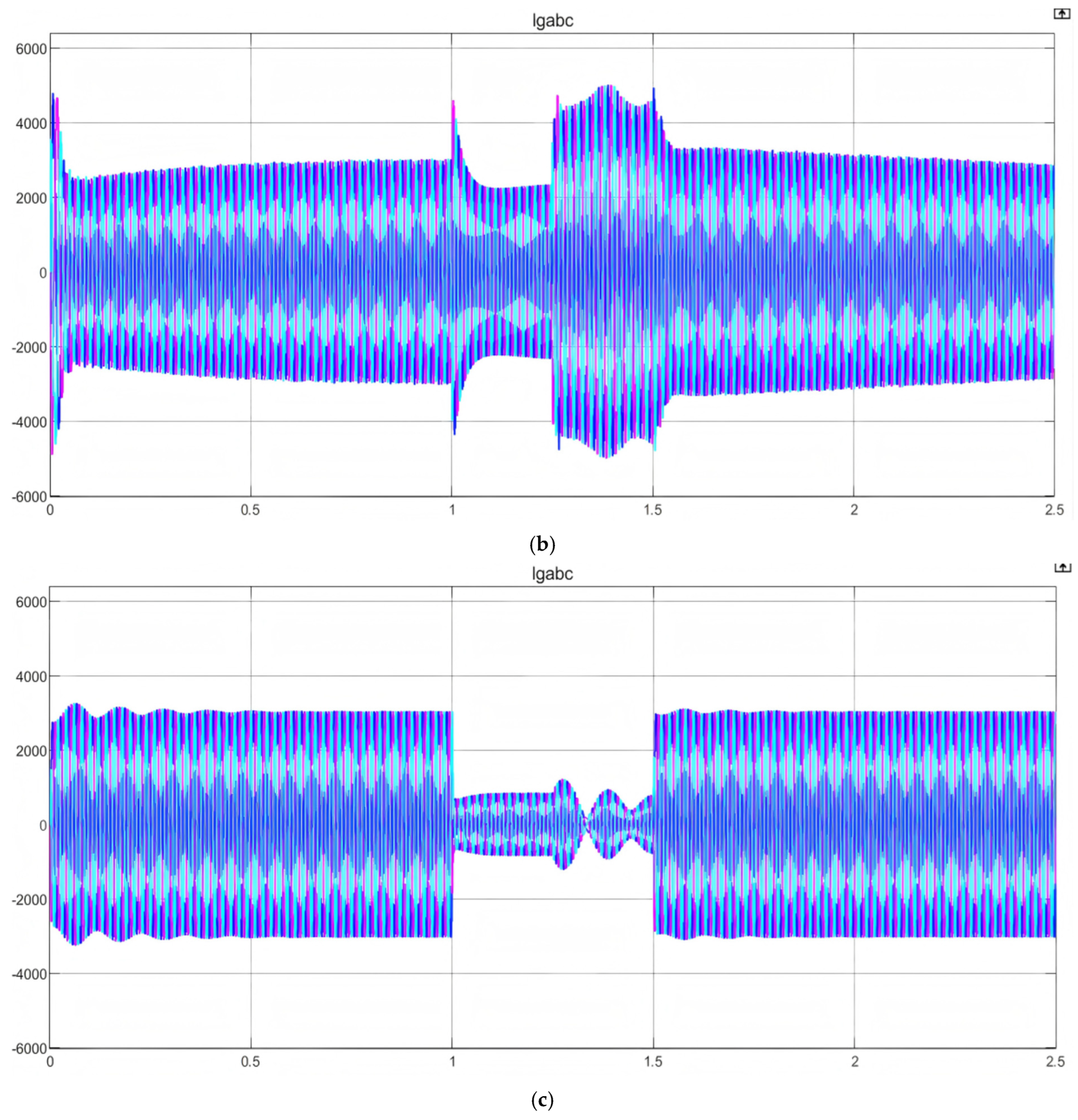
Figure 12 shows the machine-end current waveforms of the DFIG under three different control modes, PI, PI+Crowbar, and MP-CC+Crowbar, when the grid voltage drops to 20%. Analyzing the waveforms, we can see that under the effect of PI control, when the grid voltage drops, the machine-end current increases significantly. With PI+Crowbar control, the machine-end current is effectively controlled during the period of crowbar input, but the long-term input of the crowbar circuit is not conducive to the recovery of the grid voltage, and when the crowbar circuit is removed, the machine-end current increases again. The above situation is not conducive to the smooth realization of the low-voltage crossing of the DFIG. When MP-CC+Crowbar control is used, when the grid voltage drops, its machine-end current is effectively controlled during the entire voltage drop period, which effectively improves the low-voltage crossing capability of the DFIG.
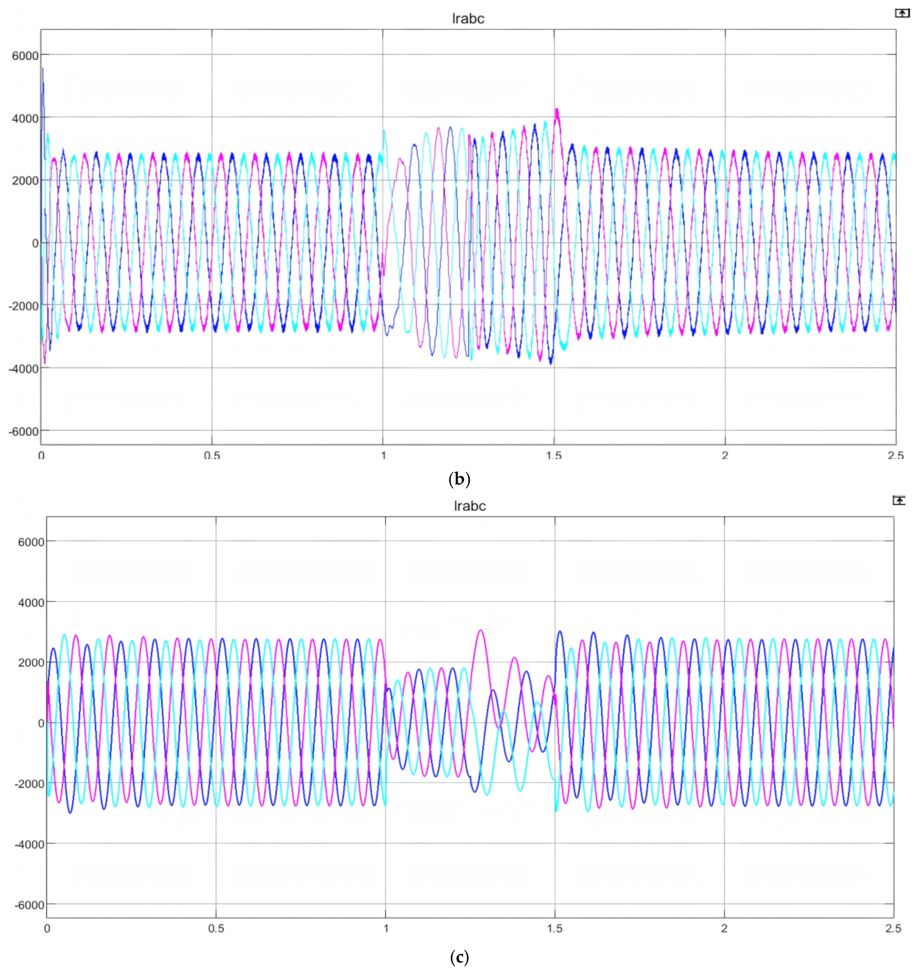
Figure 13 shows the rotor-side current waveform of the DFIG under three different control modes, PI, PI+Crowbar, and MP-CC+Crowbar, when the grid voltage drops to 20%. As can be seen from the figure, under the control effects of PI and PI+Crowbar, the change in the rotor-side current is basically consistent with the change in the machine-side current. When only the PI control strategy is used for control, the rotor-side current increases significantly during a fault, while when the PI+Crowbar circuit is used for control, the rotor-side current is only controlled during the crowbar input process. The above two situations are not conducive to the smooth realization of the low-voltage ride-through of the doubly fed wind turbine. When MP-CC+Crowbar control is used, the rotor current does not increase significantly during the voltage drop, and the LVRT capability of the DFIG is significantly improved.
The peak values of the current waveforms are summarized in
Table 3. Based on the data in the table and figures, it can be seen that the MP-CC+Crowbar control method demonstrates superior control capabilities compared to the other two control strategies.
Figure 14 shows the electromagnetic torque, DC voltage, and reactive power waveforms of the DFIG under three different control modes, PI, PI+Crowbar, and MP-CC+Crowbar, when the grid voltage drops to 20%. It can be seen from the waveform that under the PI control mode and the PI+Crowbar control mode, the electromagnetic torque fluctuates to a certain extent, and the fluctuation is more severe when the grid voltage drops. When the MP-CC+Crowbar control strategy is used, the fluctuation of the electromagnetic torque is minimal, and it remains basically stable during the grid voltage drop. Therefore, the use of the MP-CC+Crowbar control strategy can effectively improve the stability of the DFIG during LVRT.
Under both PI control and PI+Crowbar control methods, the DC bus voltage fluctuates significantly throughout the process, rising to approximately 5000 V during a fault. However, the MP-CC+Crowbar control strategy effectively suppresses the DC bus voltage fluctuations, maintaining it at around 1200 V throughout the fault period. Therefore, the MP-CC+Crowbar control strategy can effectively protect the DC bus voltage safety.
Analysis indicates that the standalone PI controller causes the turbine to draw excessive reactive power during sags, which is detrimental to system stability. In contrast, the MP-CC+Crowbar scheme outperforms the PI+Crowbar configuration by minimizing this reactive intake, offering a clear advantage for grid voltage support.
Based on the above analysis, the use of the MP-CC+Crowbar control strategy makes the motor parameters more stable during voltage drop, which can effectively improve the LVRT capability of the DFIG. The control strategy combined with MP-CC+Crowbar has good performance in controlling multiple parameters, especially the rotor-side current. The use of this control method significantly enhances the LVRT capability of the DFIG. However, the fault analysis conducted above is limited to the analysis of three-phase faults, and no research has been conducted on asymmetric faults which are more likely to occur under real-world conditions. Moreover, the grid faults in actual operating conditions are complex and variable. Future research should focus on improving the LVRT capability of the DFIG under various grid faults and conduct separate studies on different types of grid faults to ensure that the wind turbine remains connected to the grid during a fault, so that the DFIG has good stability in the face of various faults.
5. Conclusions
This paper first establishes a mathematical model of the DFIG, models its different components, and applies three distinct control strategies based on it. The two types of control methods, the improved control strategy and the additional hardware circuit, are combined to study the LVRT process of the DFIG. In the simulation study, by analyzing the waveforms of various parameters, the control effects of three different control methods were compared when the grid voltage dropped to 50% and 20%. Through theoretical derivation and experimental analysis, the following conclusions can be drawn:
The MP-CC+Crowbar control strategy based on the improved RK4 algorithm overcomes the shortcomings of traditional discrete models in terms of insufficient accuracy in fault transient prediction, provides excellent control over the rotor-side current, and effectively improves the low-voltage ride-through capability of doubly fed induction generators during voltage dips.
Compared to the original PI control strategy, the MP-CC control strategy achieves more effective regulation of parameters such as DC bus voltage, electromagnetic torque, and reactive power, especially during voltage drops. Therefore, the new control strategy DFIG has better regulation ability when the grid voltage fails.
Combining the two types of control methods, improved control strategy and additional hardware circuit, can effectively improve the problems existing in a single measure. The control strategy based on MP-CC+Crowbar has good control capabilities during the entire voltage drop period, while also ensuring stable operation of the unit after the fault ends. It effectively improves the shortcomings of traditional control methods, improves the LVRT capability of the DFIG, and significantly improves the operating stability of the DFIG during LVRT.
Through the above conclusions, the use of the MP-CC+Crowbar control strategy can make the DFIG have good performance in the whole process of voltage drop and operate more smoothly in the whole process of LVRT. Although improving the MP-CC strategy increases computational complexity, the feasibility analysis above shows that it is capable of real-time operation on modern high-performance DSP or FPGA platforms. Compared to its significant contributions in improving low-voltage ride-through capability and system stability, this investment in computational resources is justified. Therefore, reducing the resource consumption of MP-CC control while maintaining its effectiveness, and simultaneously improving the traditional crowbar structure, will be important research directions in the future.