2. Human-Pose Recognition Algorithm
Human-pose recognition based on traditional algorithms generally adopts various image-processing approaches, such as neural-network models, template-matching, feature-point detection and edge detection. These methods perform pose classification or extract joint-point information for targets in images, so as to realize pose recognition for single-person, two-person or multi-person scenarios [
3,
4]. Traditional human-pose-recognition algorithms have inherent limitations in algorithm architecture and model structure, which bring about many drawbacks in practical applications. They are only suitable for limited scenarios and exhibit poor performance under complex backgrounds. Meanwhile, the algorithms are highly sensitive to interferences including target occlusion and dynamic pose variation, resulting in a significant drop in recognition accuracy.
To overcome the above shortcomings, this paper adopts a deep-learning-based human-pose-recognition algorithm. Convolutional Neural Network (CNN) is utilized to extract human-pose information from images, and the model is trained on human-image datasets. Compared with traditional algorithms, the proposed method can capture human-pose information more accurately and extract richer semantic features, and achieves better performance when dealing with complex scenarios and diverse data [
5,
6,
7].
In this work, BlazePose from MediaPipe0.10.1 is adopted as the off-the-shelf pose estimation backbone. Direct benchmark evaluation on public datasets is not the focus of this paper; instead, we target the practical imitation performance within our robot dance-imitation scenario. Comparative experiments against OpenPose 1.7.0 and template-matching methods are conducted under our real-world test scenarios (see
Section 5.3.4), which quantitatively demonstrate the advantages of the adopted lightweight pipeline for monocular-vision-driven robot imitation tasks.
2.1. Deep-Learning-Based Human-Pose Recognition Algorithm
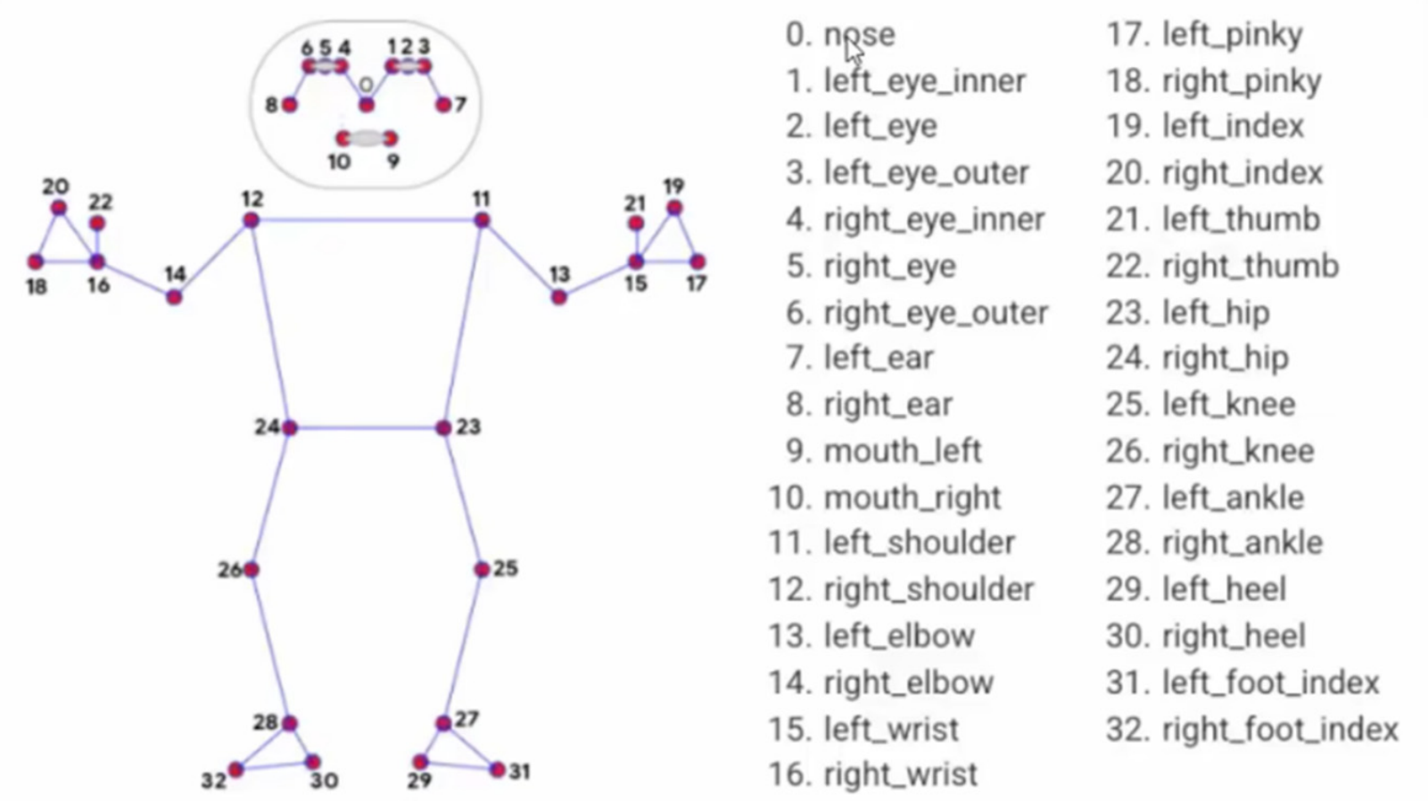
Representative deep-learning-based human-pose-recognition models include OpenPose and BlazePose. BlazePose is a lightweight convolutional neural-network model for human-pose estimation, which can detect 33 body key-points of a single person [
8]. Its skeleton topological structure is shown in
Figure 1. The model adopts a detector-tracker architecture for pose recognition. Its working mechanism is as follows: the tracker predicts key-point coordinates, the human-presence status in the current frame, and the Region of Interest (ROI), which refers to the image region covering all features of the target for key-point detection. The detector relies on the fast on-device face detector to predict the mid-point of human hips, the radius of the circumscribed circle enclosing the human body, and the tilt angle of the straight line connecting the mid-points of shoulders and hips. In the pose-detection procedure, the detector first locates the ROI in the initial frame. Then the tracker estimates all 33 key-point positions based on this ROI. For subsequent frames, the predicted key-points from the previous frame are adopted to update and locate the ROI [
9].
The neural network of this model adopts a combined strategy of heatmap, offset and regression. During network training, heatmap loss and offset loss are combined for parameter optimization. Corresponding output layers are removed before inference, and heatmaps are utilized to supervise lightweight embedding. Finally, the encoder network performs regression for all joint points [
10]. To predict occluded key-points, the model introduces a per-point visibility classifier, which belongs to the occlusion-aware scheme in machine vision. It judges the visibility status of each skeletal key-point to mitigate detection difficulties caused by target occlusion in images.
In the experiment, the video file is processed frame-by-frame by the BlazePose model, and a dataset of 33 human body joint points is output. Each key-point contains the abscissa x, ordinate y, and the recognition visibility v of the corresponding joint. The obtained joint-point position information can completely preserve the pose features of the detected target. After preprocessing and kinematic analysis, such data can be directly applied to the motion control of the dancing robot.
2.2. Implementation of Control Algorithm Based on BlazePose Human-Pose Recognition
This paper designs the visual algorithm for a dancing robot based on the BlazePose model on the Python 3.7 platform. The main implementation steps of the algorithm include video extraction, invoking BlazePose from the MediaPipe library for human-pose recognition, acquiring key-point position information, processing position data to calculate bone-joint angles, serial-port communication configuration, and control-logic design.
2.2.1. Video Extraction and Pose Recognition
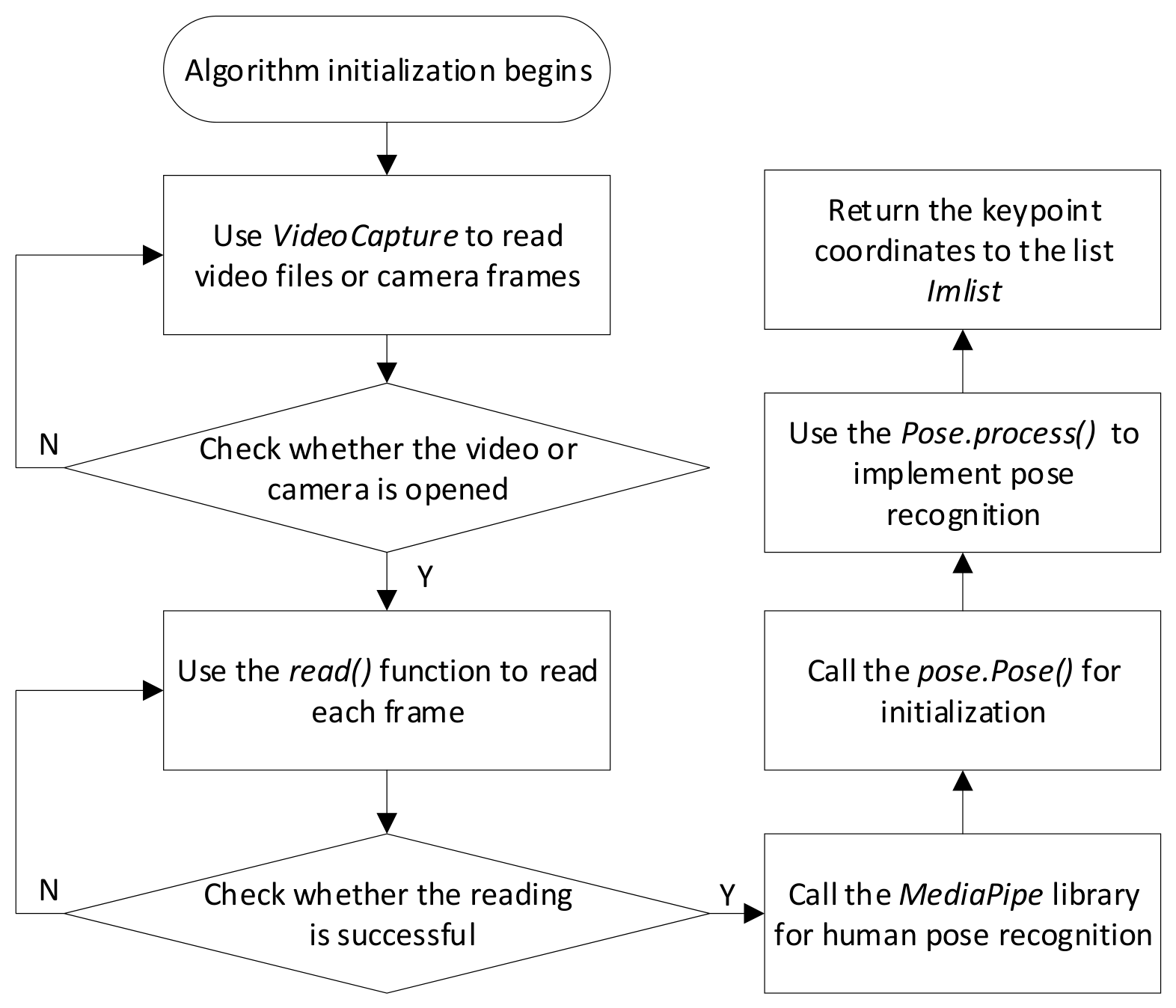
For video extraction, the VideoCapture function from Python’s cv2 (OpenCV) library is adopted. It can obtain video streams from local video files at specified paths or camera devices. Among its member functions, isOpened() judges whether the video file or camera is opened successfully; the read() function returns a read-status flag together with a single video frame. It not only can verify the validity of video reading, but can also sequentially read each frame into the matrix variable image within a loop.
Pose recognition is realized by invoking the pose class in the MediaPipe library. MediaPipe Pose is a high-fidelity machine-learning solution for human-pose tracking built upon BlazePose research outcomes [
11]. BlazePose is a lightweight convolutional neural-network architecture for single-person key-point detection. After each video frame is successfully read, the pose.process(image) function is called to perform pose estimation for each frame. This function returns the 3D-coordinate sequence of 33 skeletal key-points predicted by the BlazePose model. Running on a single mid-tier mobile-phone CPU, BlazePose is 25–75 times faster than OpenPose running on a 20-core desktop CPU, and can achieve real-time performance. The coordinate sequence is stored in the list lmlist for subsequent data parsing and processing. The workflow of video extraction and pose recognition is shown in
Figure 2.
2.2.2. Key-Point Data Processing and Bone-Angle Calculation
The output of pose recognition consists of three-dimensional position information of 33 skeletal key-points. Since the dancing robot in this paper only imitates simple dance movements, only the skeletal key-points of the trunk, shoulders, hips and other parts (key-points numbered 11~16 and 23~28 in
Figure 1) need to be extracted. To calculate bone-joint angles, this paper adopts the method of “constructing spatial vectors from key-points and solving bone-joint angles by vector-included-angle operation”. Before that, the raw coordinates output by the model should be converted into 3D coordinates in real physical space. As introduced above, BlazePose outputs 33 sets of joint data containing abscissa
x, ordinate
y and joint-point visibility
v. The direction and sequence of the original
x,
y,
z coordinate axes need to be adjusted to obtain the practical coordinate system
x′,
y′,
z′, so as to acquire key-point coordinates under the real-world coordinate frame.
After obtaining the key-point coordinates in the practical coordinate system, the included angles of each bone joint can be solved. The specific calculation methods are described as follows:
- (1)
Angle calculation for Single-DOF (single-degree-of-freedom) joints
Single-DOF joints correspond to key-points numbered 13, 14, 25 and 26 in
Figure 1. The connected bone segments at these joints can only rotate around one single direction. Taking key-point No. 13 as an example, the solving procedure of the angle for single-DOF joints is illustrated below.
Let practical-world coordinates of points 11, 13, 15 be
. Define the vectors as follows:
The included angle
at marker 13 is computed by
- (2)
Angle calculation for Double-DOF (double-degree-of-freedom) joints
Double-degree-of-freedom joints correspond to the key-points numbered 11, 12, 23, 24, 26 and 27 in
Figure 1. Two bone segments are connected at these joints, so their motion posture cannot be fully described by only one single angle parameter. In terms of robot motion control, each servo only provides a single-degree-of-freedom rotation. To reproduce the motion of such joints, at least two angle parameters are required, which means that two or more servos should be configured at the corresponding robot joint. Taking key-point No. 11 as an example, the method of characterizing the motion features of bone segment 11–13 with two angles is illustrated below:
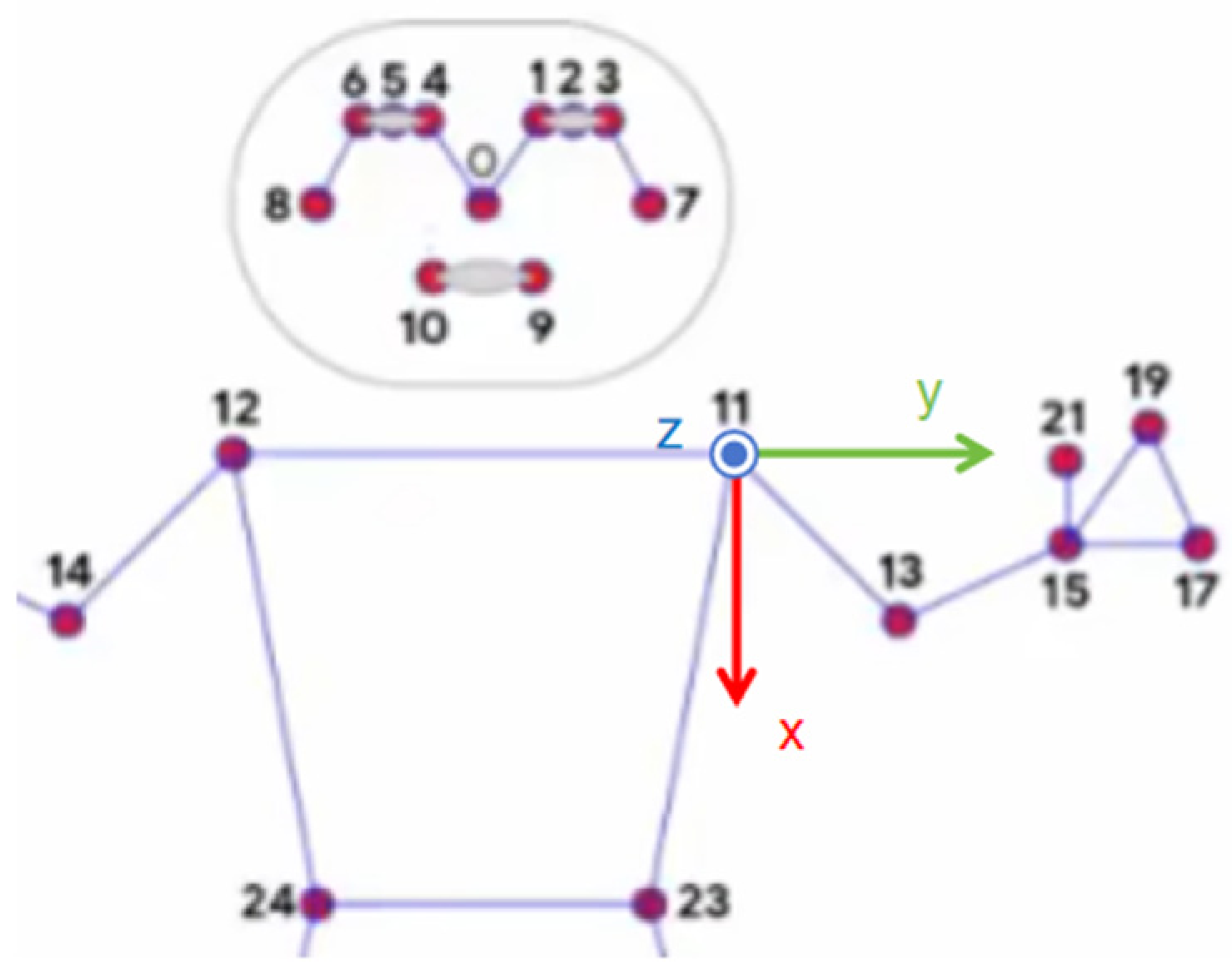
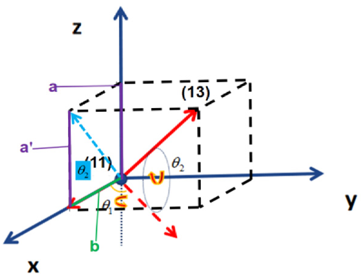
A reference coordinate system is established for key-point 11, as shown in
Figure 3. The
y-axis is collinear with segment 12–11; the
x-axis is perpendicular to the
y-axis and coplanar with the plane formed by segments 11–12–24; the
z-axis is perpendicular to the plane spanned by the
x-axis and
y-axis, forming a rectangular coordinate frame. When calculating the two angles at key-point 11, considering the anatomical feature that the human shoulder is perpendicular to the upper arm, the initial orientation of arm segment 11–13 is set along the x-axis. Two rotation angles,
and
are calculated, corresponding to rotating the initial
x-axis around the
z-axis first and then around the
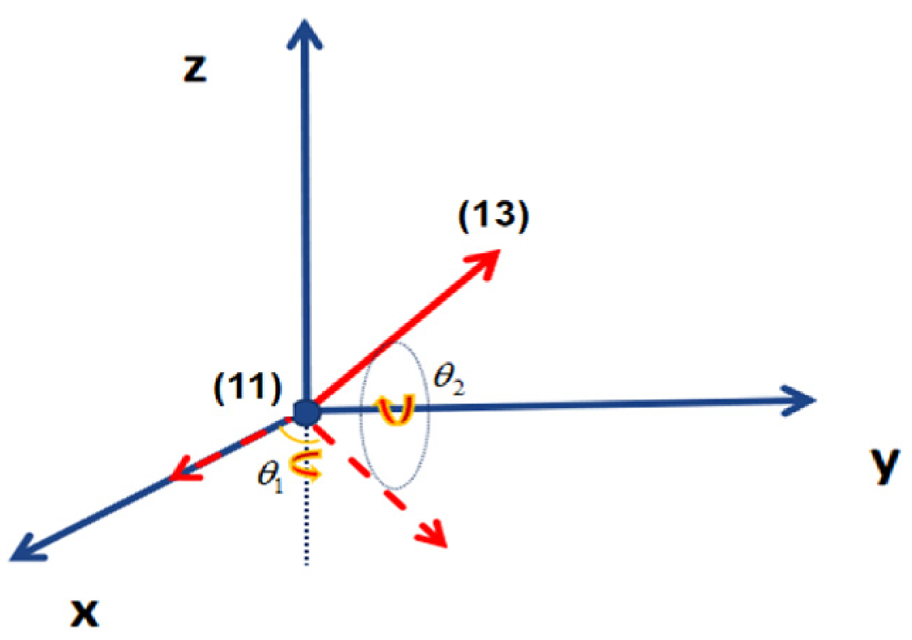
y-axis to the direction of the actual arm segment 11–13. The obtained angles are the target angles of the two servos corresponding to key-point 11. The angle calculation method for double-DOF joints is illustrated in
Figure 4.
In
Figure 4, vector 11–13 (
) is obtained by sequentially rotating the initial vector along the x-axis around the z-axis and the y-axis. Angle
is complementary to the included angle formed by vectors
and
, namely,
For the calculation of angle
rotating around the
y-axis, angle
is equal to the included angle between vector
(the projection of vector
onto the xOz plane) and the
, as shown in
Figure 5.
Let the projections of vector
on the
x-axis and
z-axis be
and
, respectively. Translating
to the position of
in
Figure 5,
can be expressed as
where
,
.
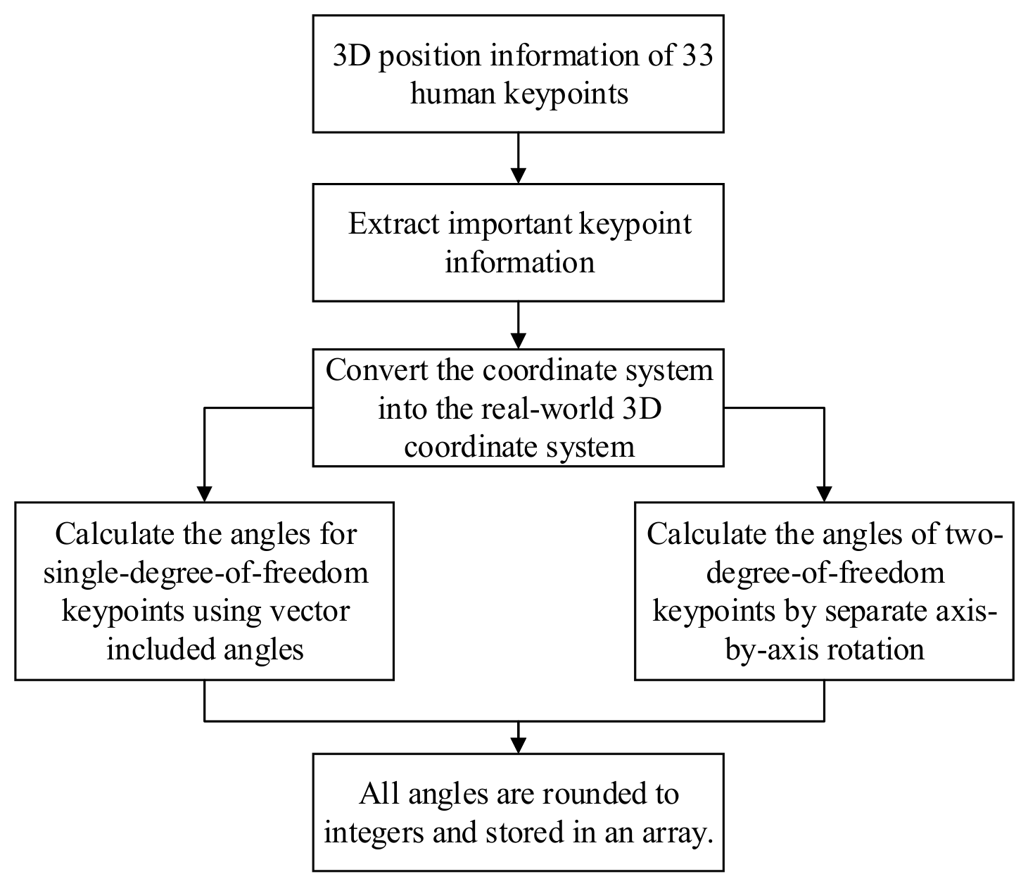
The two-point method can be adopted to calculate the angles of single-DOF and double-DOF joints. With one joint selected as the reference point, two other joint points are defined, and the angles between the
x-axis and the line connecting the reference point to each target joint are calculated. This method reduces the angle error caused by relative jitter between key-points and realizes accurate angle measurement. Finally, all calculated angles of important joints are rounded and stored in an array to facilitate subsequent data transmission. The data processing workflow is shown in
Figure 6.
2.2.3. Algorithm Performance Analysis
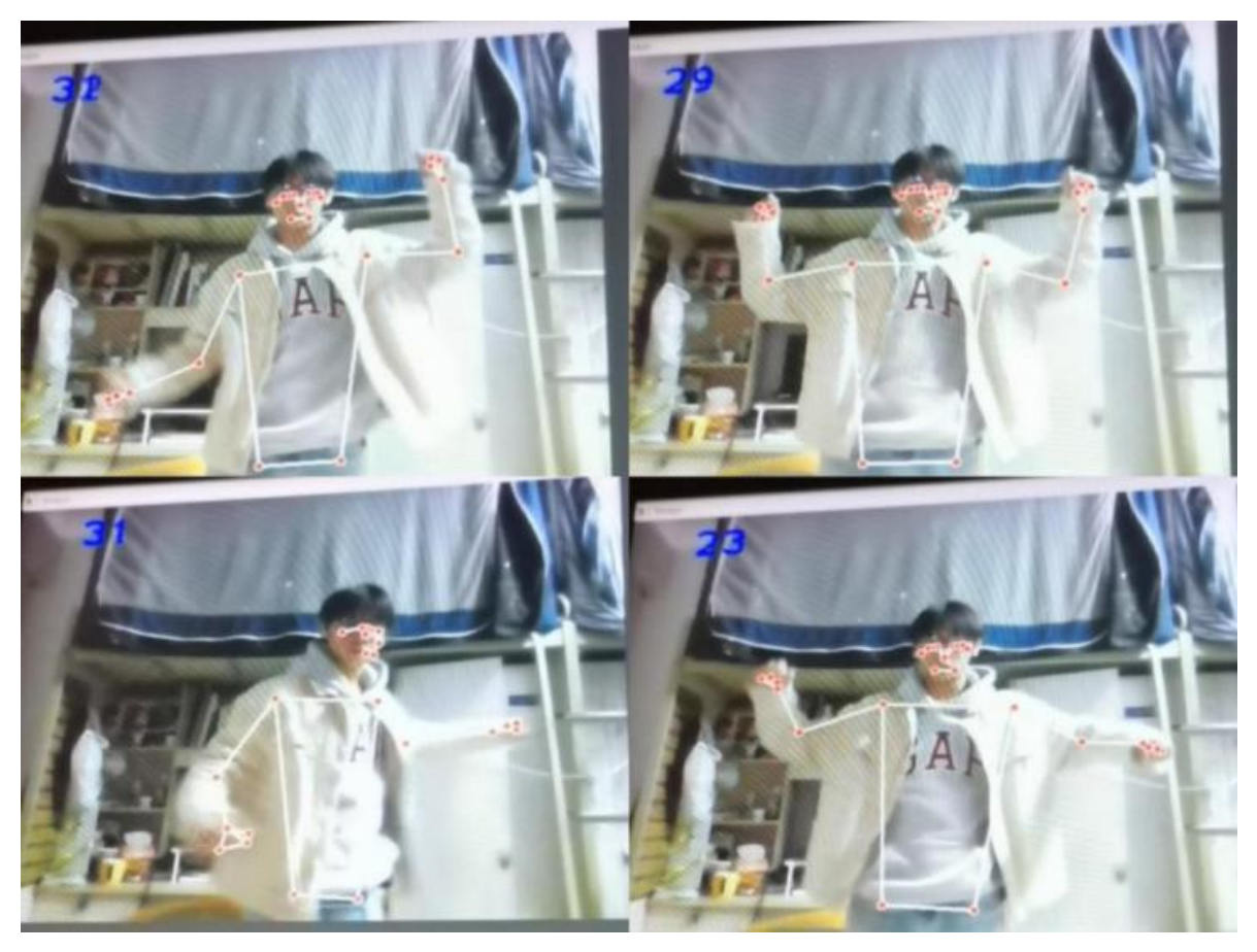
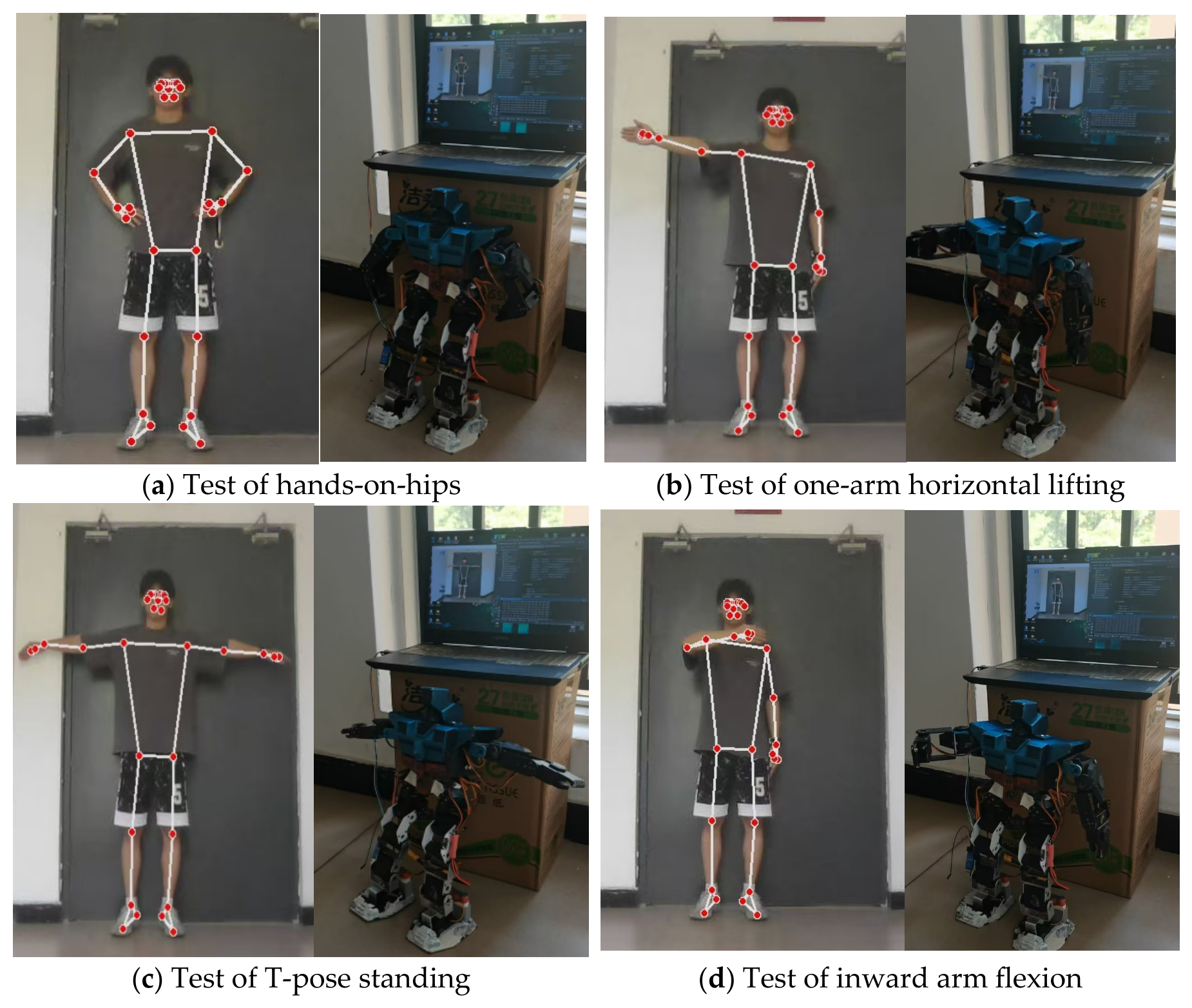
Figure 7 shows the key-point recognition results of images captured by the computer front camera through the vision module. The human key-point recognition model adopted in this paper can rapidly estimate 26 major human key-points with high detection accuracy and favorable real-time performance. The model can recognize human joints even under partial occlusion. Conventional image recognition algorithms usually suffer from accuracy degradation caused by occlusion, and the excellent anti-occlusion capability is a prominent advantage of the adopted model.
3. Robot Mechanical-Structure Design
3.1. Joint-Mechanism Design of the Dancing Robot
The BlazePose topology diagram (
Figure 1) involves major human joints including shoulders, elbows, hips, knees and ankles. During robot structural design, the motion characteristics of these joints should be comprehensively considered to ensure that the designed mechanism can reproduce human joint movements.
Since the dancing robot only imitates simple human dance movements, the robot structure can be reasonably simplified:
- (1)
Elbow and Knee Joints:
When the robot performs dance movements, the elbow and knee joints mainly realize flexion-extension motion, and independent rotation of the forearm or crus rarely occurs. Therefore, the elbow and knee joints can be simplified as single-DOF joints.
- (2)
Shoulder and Hip Joints:
The shoulder and hip joints are typical multiaxial ball-and-socket joints capable of three-axis rotation. However, limited by the machine-vision pose recognition capability, the algorithm can only obtain the position information of joint key-points. For instance, the rotation of the upper arm about its longitudinal axis at the shoulder joint cannot be determined, and the same problem occurs at the hip joint. As a result, it is difficult to reproduce the axial rotation of the upper and lower limbs, and these joints are simplified to double-DOF configurations. Although this simplification may reduce the accuracy of motion imitation, a double-DOF structure allows the elbow or knee to reach any point on a sphere centered at the shoulder or hip joint with the connecting rod length as the radius. Therefore, simplifying the shoulder and hip joints into double-DOF joints has little impact on the overall function of the dance imitation robot.
- (3)
Ankle Joint:
The ankle joint is a trochlear (hinge) joint with four primary motion modes: flexion, extension, inversion and eversion. Flexion denotes toe movement toward the body, whereas extension refers to toe movement away from the body; inversion represents foot rotation toward the medial side of the body, and eversion toward the lateral side. Therefore, the motion of the ankle joint can be regarded as double-DOF motion.
3.2. 3D Modeling of the Dancing Robot
SolidWorks2022 is adopted for the 3D modeling of the robot structure. Servos are used as joint actuators, and a servo-linkage mechanism is designed to endow the robot with better anthropomorphic characteristics.
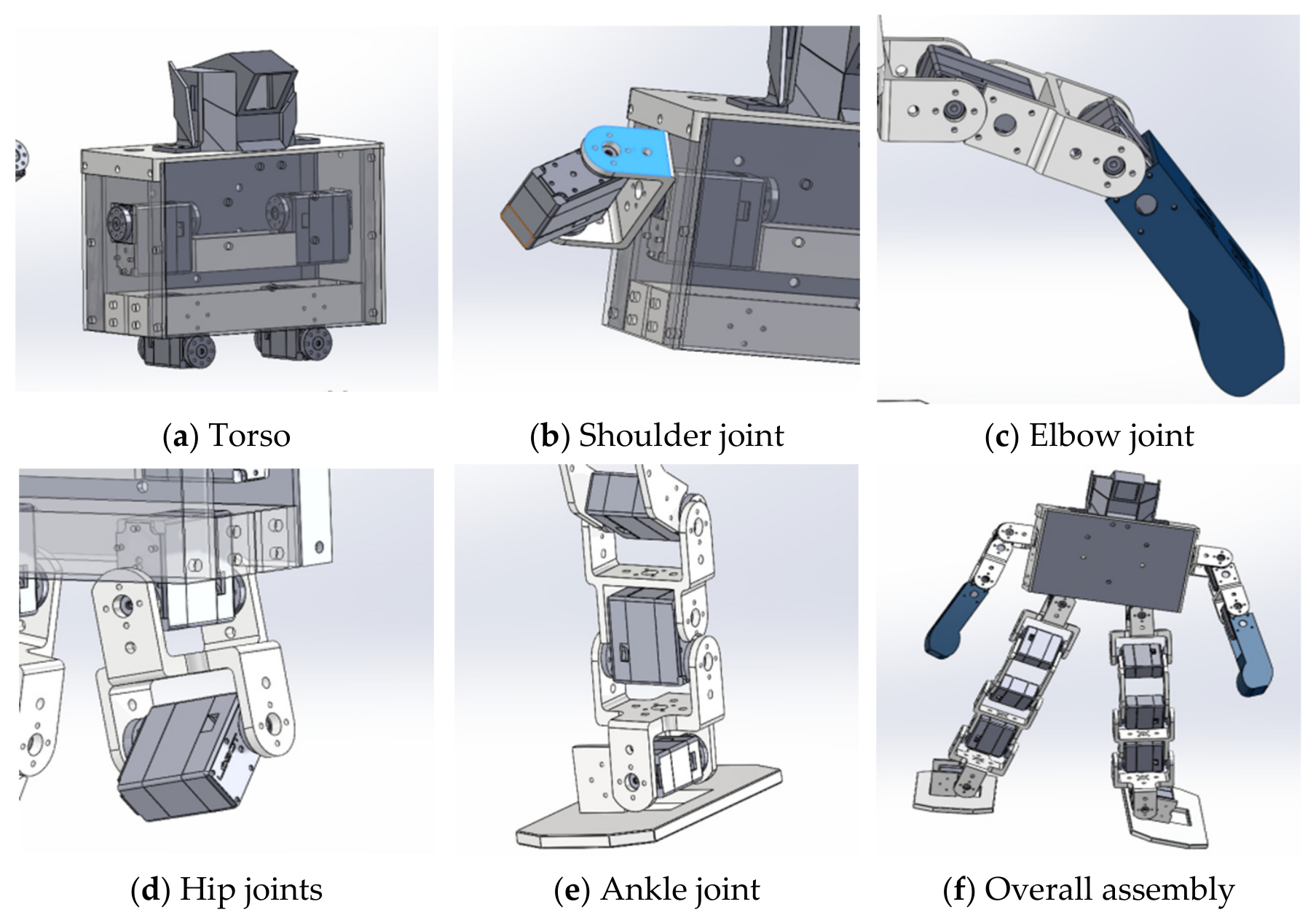
The 3D robot model consists of four main parts: head, torso, upper limbs and lower limbs. The torso is assembled from five plates reinforced by connecting parts, where servos are mounted. The top plate fixes the robot head, and the internal space of the head accommodates the hardware of the vision system. All plates are fastened by bolts to form a box structure with reserved holes for circuit board installation and cable routing, as shown in
Figure 8a. The structures of the shoulder, elbow, hip, knee and ankle joints are illustrated in
Figure 8. Each servo realizes uniaxial rotation corresponding to one degree of freedom. The number of servos is configured according to the DOF requirement of each joint, and servos are connected by linkages to form the robot limbs. A drawing of the overall assembly of the robot is presented in
Figure 8f. The robot is equipped with 16 servos in total, and the main body can be fabricated by assembly with 3D-printed connectors.
4. Robot Motion Solution
The motion trajectory of the dancing robot is planned according to the robot 3D model and machine vision model. The robot’s movements are realized by the rotation of servos at each joint, so motion planning corresponds to the control planning of these 16 servos. Joint coordinate data are obtained using the BlazePose-based pose estimation algorithm. Developed by Google, BlazePose is a lightweight human pose-tracking model with an accuracy three times that of previous similar models. It supports on-device real-time human pose-tracking, runs at over 30 FPS on Pixel 2 mobile phones, and detects 33 body landmarks. Virtual landmarks are adopted to improve stability for complex motions, enabling cross-platform deployment on mobile devices, Web and desktop terminals. Data processing and spatial geometric analysis are performed on the landmark coordinates to calculate joint angles. The joint angles extracted by visual recognition are used to control the rotation of corresponding servo motors on the dancing robot.
In short, if the joint angles acquired by the vision system are adopted to control the dancing robot, the motion trajectory planning problem can be divided into two parts: the control of the arm linkage from the shoulder joint to the end effector (hand), and the control of the leg linkage from the hip joint to the end effector (foot).
- (1)
Arm Motion Planning
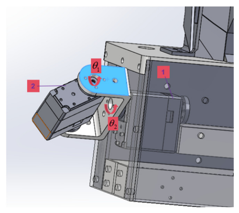
In the arm motion model, the shoulder joint has two degrees of freedom controlled by two servos. Based on the coordinate information of the elbow joint, the pose estimation algorithm calculates two rotation angles
and
of the upper arm around the front vertical axis and the lateral vertical axis of the body, respectively. During robot control, the tiny error caused by the installation distance between the two shoulder servos can be ignored. Servo 2 rotates by angle
and Servo 1 rotates by angle
, as shown in
Figure 9. The elbow servo only needs to rotate to the joint angle obtained by machine vision recognition. With this planning method, the robot arm can effectively imitate human dance postures and realize bionic arm motion reproduction.
- (2)
Leg Motion Planning
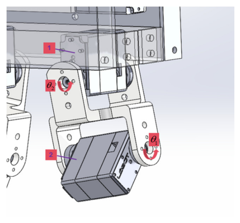
The hip joint in the leg model is designed with two degrees of freedom. Different from the linear arm linkage, the thigh structure is not a straight connecting rod, which increases the difficulty of leg motion planning. For the servo control of the hip joint, the pose recognition algorithm calculates two rotation angles of the thigh, namely angle
rotating around the vertical axis of the body side and angle
rotating around the vertical axis of the body front. To simplify the control process, a virtual line segment connecting the upper and lower servos of the hip joint is constructed to equivalently replace the physical thigh linkage. Accordingly, the hip joint servos are controlled by rotating Servo 2 by angle
and Servo 1 by angle
. The motion planning principle is illustrated in
Figure 10.
The motion planning of the knee joint is consistent with that of the elbow joint. The corresponding servo only needs to rotate to the knee joint angle obtained by machine vision recognition.
To realize ankle joint motion planning and prevent the robot from tipping over during movement, two motion constraints are defined: the foot remains in contact with the ground, and the torso stays perpendicular to the ground with the robot head pointing vertically upward. With these constraints, ankle motion planning can be performed.
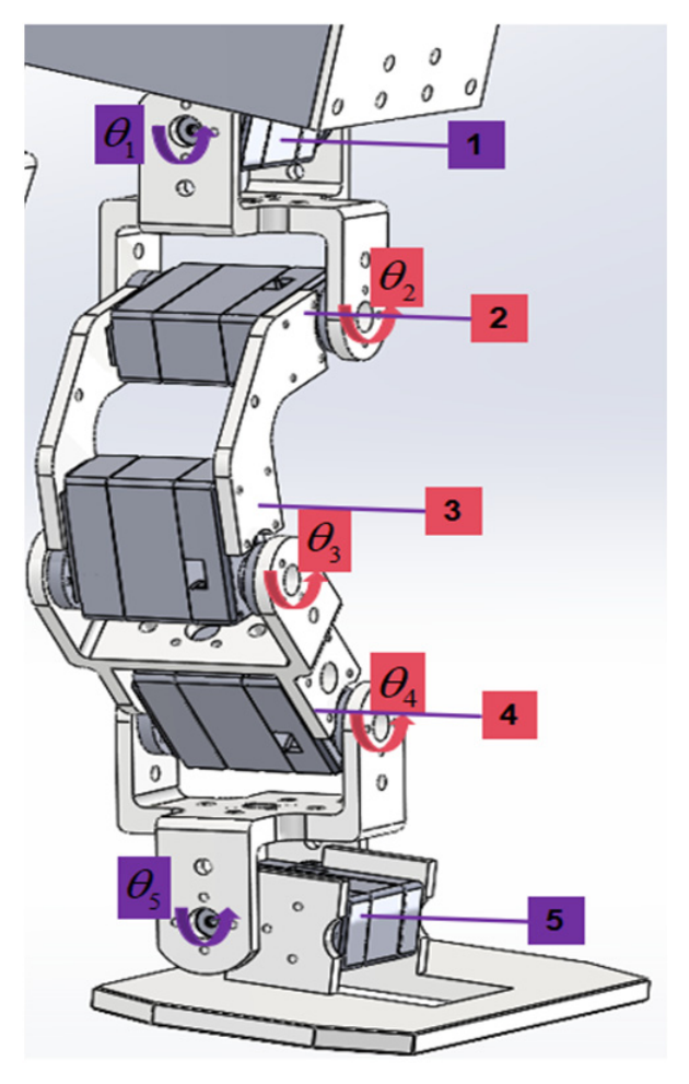
Figure 11 shows a structural model of a single robot leg. The rotation axes of Servo 1 and Servo 5 are parallel, and the rotation axes of Servo 2, Servo 3, and Servo 4 are parallel. To satisfy the above constraints, the rotation of servos about the two axes should be controlled separately.
For rotation about the axes of Servo 1 and Servo 5, qualitatively, the rotations of Servo 1 and Servo 5 must counteract each other to maintain the position of the torso and foot, i.e.,
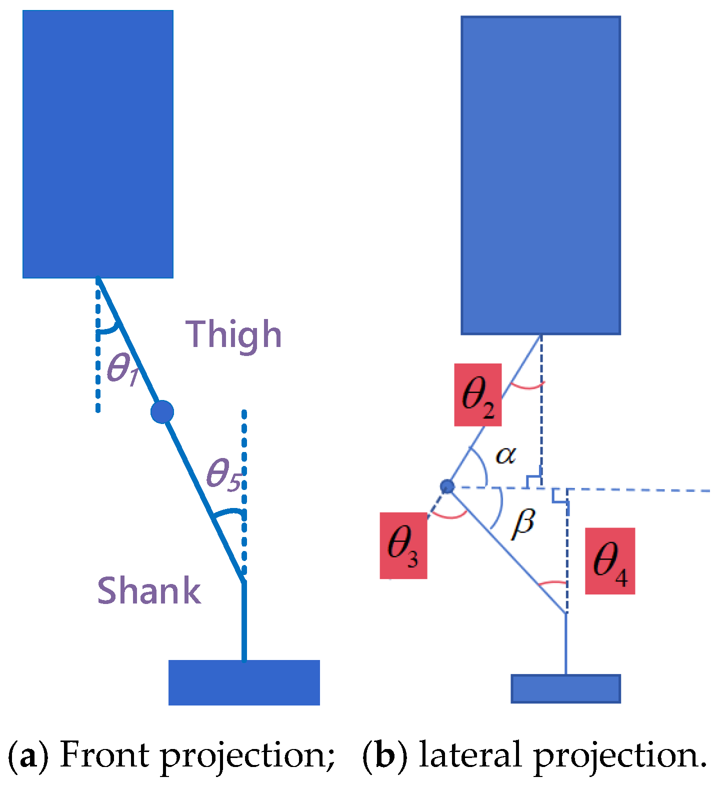
. Quantitatively, the leg model is simplified and projected onto the plane perpendicular to the rotation axes of Servo 1 and Servo 5 (
Figure 11), and the following relation can be derived from geometric constraints:
.
For rotation about the axes of the remaining servos, the leg model is simplified and projected onto the plane parallel to the lateral side of the torso, as illustrated in
Figure 12. The corresponding geometric relations are expressed as follows:
The rotation angle of servo 4 is solved as
Note that servo angles represent deflections relative to mechanical home positions, which are defined in lower-level firmware.
The above completes the motion planning for the arms and legs of the dancing robot. It should be noted that the servo rotation angle is defined as the deflection relative to its initial position. Hence, the initial position of each servo must be determined in advance for motion planning, and this parameter will be specified in the lower-level controller programming.