1. Introduction
In satellite communication systems, the feed antenna is used to provide symmetric illumination, with a uniform radiation pattern, of a reflector mounted on board the satellite, which amplifies and redirects the signal within the operating frequency range toward the ground-based receiver. This requires an appropriate modal balance; therefore, the corrugated horn antenna was selected for investigation. It consists of a circular waveguide that progressively expands from the input section toward the aperture, with grooves (corrugations) of different periodicities introduced along the inner walls. These corrugations provide the required HE
11 modal balance, a symmetric radiation pattern, and intrinsically low cross-polarization levels [
1,
2].
In comparison with the smooth-wall horn antenna considered in the previously studied articles, in which the propagating mode in the waveguide is TE11, the resulting field distribution is asymmetric, since the Ex and Ey components are not equal. This leads to increased cross-polarization and an elliptical main beam. The introduction of corrugations transforms the conducting walls into surfaces characterized by an infinite surface impedance, imposing an equivalent boundary condition on both field components. As a result, the hybrid HE
11 mode is established, producing an almost perfectly symmetric aperture field distribution, with a cross-polarization discrimination of XPD > 30 dB. Such a value cannot be achieved with other horn antenna configurations without corrugations [
3].
The field amplitude distribution at the aperture of a Gaussian-profile corrugated horn provides an optimal coupling to the fundamental HE
11 mode of the Gaussian beam, resulting in an illumination efficiency of
ill = 70–80%, which is higher than that obtained for a smooth-wall antenna, where
ill = 50–55% [
1,
2]. The 20% improvement in illumination efficiency can be associated with an increased reflector gain for the same physical aperture area. Gaussian corrugations significantly reduce the secondary lobes due to the decreasing field distribution toward the aperture edges. Consequently, a Side Lobe Level (SLL) below −25 dB can be obtained, compared with values below −17 dB for a smooth-wall antenna with a uniform field distribution. The reduced secondary-lobe levels minimize the potential for interference with neighboring satellites [
1,
2].
The simultaneous operation within the X-band and Ku-band using a single antenna system is considered to be of considerable practical interest, as it enables the same antenna configuration to provide both uplink and downlink functions over the two frequency bands without requiring separate antenna assemblies. This approach consequently reduces the overall system mass, structural complexity, and implementation costs [
4].
The X-band is used for satellite communications and operates over the 7.25–7.75 GHz range for Space-to-Earth communication (downlink) and the 7.9–8.4 GHz range for Earth-to-Space communication (uplink) in the Fixed-Satellite Service, with these allocations being reserved exclusively for governmental or military applications. The Ku-band is used in Europe over the 10.7–12.75 GHz frequency range for direct satellite broadcasting services, with uplink operation at 14–14.5 GHz for Fixed-Satellite Services [
5]. The antenna was therefore designed to operate over two frequency bands, providing several advantages. This configuration eliminates the need for two separate feeds and the associated complex duplexing system while reducing the mass and volume of the feed system, as well as the overall manufacturing costs. A dual-band system can also switch between the two frequency bands according to propagation conditions. For example, the X-band provides improved performance under interference and adverse atmospheric conditions, whereas the Ku-band provides a wider available bandwidth, allowing higher data-transfer rates.
For the development of this type of corrugated horn antenna intended for satellite communications, a review was conducted on existing antenna configurations that have already been implemented, such as the Gaussian-profile horn antenna developed by Teniente et al. [
6,
7] with a pure Gaussian-profile, achieving a cross-polarization discrimination of XPD ≥ 40 dB and a maximum coverage gain of approximately 18 dB [
6,
7].
In commercial applications, dual-band corrugated horns frequently employ structures with distinct corrugation depths for each frequency band of interest, as in the solution patented by Huang et al. [
8], in which the first corrugation section serves the lower frequency band, while the second section serves the upper band [
8]. A similar approach based on separate components consists of a smooth-wall horn coupled to two separate corrugated duplexers and a septum-type polarizer to cover the two uplink/downlink frequency bands associated with the Ku-band [
9].
A configuration similar to the antenna investigated in the present study is the hybrid corrugated horn with ridges proposed by Manshari et al. [
10], covering the X-band and Ku-band (6–20 GHz), with a gain ranging from 12 to 18 dB and an approximately constant beamwidth [
10]. The requirement for dual-band operation is not limited to radiating elements used in satellite systems but is also found in current commercial solutions intended for nanosatellites, such as the K/Ka-band horn antenna developed by PicoSaTs for CubeSat platforms [
11].
In contrast to these approaches, which employ either distinct corrugation sections with constant depth over specific portions of the antenna or external duplexing components, the present work proposes a continuously variable corrugation-depth profile governed analytically by a single normalized Gaussian function along the entire length of the horn.
For dual-band operation, previous approaches employ coaxial structures, external diplexers, or profiles with discrete corrugation depths, which introduce mechanical complexity or bandwidth limitations. This aspect is particularly important for the implementation of this type of antenna onboard a satellite, where the mass and complexity of the system directly affect the mass budget and the integration of the antenna system into the satellite platform. The present work proposes the design and optimization of a corrugated horn antenna with a normalized Gaussian profile ( = 0.42 L), operating in two frequency bands, X-band and Ku-band, intended for feed applications for reflectors incorporated into satellite communication systems. Satellite communication systems employ antenna configurations designed to provide symmetrical illumination of the reflector over the microwave frequency range. The reflector, mounted onboard the satellite, subsequently amplifies and redirects the received energy toward a receiver, such as an unmanned aerial vehicle, while relevant frequency allocations are used for military applications.
Beyond conventional horn-based feed architectures, recent work has explored alternative approaches to beam control and antenna optimization at microwave and optical frequencies, including ultrathin metalens structures for wide-angle beam steering [
12], leaky-wave antennas incorporating externally perceivable sensing functionality [
13], and physics-assisted optimization algorithms applied to Ka-band metalens antenna designs [
14]. While these planar, metasurface-based platforms target different application spaces (beam scanning and sensing) compared to the fixed-beam, circularly polarized satellite feed considered here, they illustrate a broader trend toward optimization-driven antenna design that complements the analytical profile-optimization approach adopted in the present study.
The antenna geometry is synthesized in the MATLAB computational environment, generating a two-dimensional profile that is subsequently used in the Ansys HFSS electromagnetic simulation and analysis environment to construct the complete three-dimensional antenna geometry. The resulting structure is then evaluated from an electromagnetic perspective.
The obtained results demonstrate the performance of the proposed antenna, providing an illumination efficiency of
ill = 58.8–76.7% across the four frequency ranges of interest and a cross-polarization discrimination of XPD > 30 dB over both operating bands. This paper is organized as follows:
Section 2 presents and analyzes the analytical synthesis implemented in MATLAB.
Section 3 is dedicated to the electromagnetic analysis of the corrugated horn antenna using Ansys HFSS.
Section 4 presents there results obtained fot the proposed antenna.
Section 5 provides the discussion and comparison of these results, and
Section 6 presents the conclusions of the study.
2. Synthesis of the 2D Profile of the Corrugated Horn Antenna in MATLAB
This study focuses on the design and analysis of a horn antenna with corrugated walls, for which the groove dimensions are defined to achieve optimum impedance matching and satisfy the initial requirement for optimal operation within the X-band and Ku-band. To achieve dual-band operation, the design process therefore focused on identifying a configuration capable of simultaneously satisfying the required geometric conditions for operation within both frequency bands.
To account for the variation in mathematical parameters with respect to frequency and facilitate the conversion of mathematical calculations into geometric forms required for subsequent analyses, the calculations were implemented in the MATLAB environment. This approach also allows the design parameters to be adjusted according to the electromagnetic operating conditions in order to obtain the required antenna performance. The MATLAB implementation generates a two-dimensional geometric profile that forms the basis for defining the corrugations according to a normalized Gaussian profile. The resulting geometry is then generated in a format compatible with the Ansys HFSS electromagnetic analysis environment, where the complete three-dimensional antenna profile is constructed, and its electromagnetic performance and compatibility with the intended operating frequency bands are evaluated.
In the implementation of the mathematical calculation in MATLAB, particular attention was given to satisfying the mathematical expressions defining the normalized Gaussian profile, as well as the modal balance conditions required to achieve impedance matching over the entire operating bandwidth and effective circular polarization. The HE11 modal balance condition requires the depth of each corrugation to remain within the range of to , with the corrugation slots being treated as short-circuited transmission-line stubs at their base. This propagation condition requires the wall admittance to be capacitive in order to support the hybrid HE11 mode.
Consequently, the hybrid HE
11 mode is not established, modal balance is not maintained, the impedance remains finite, and the tangential electric field is no longer zero. For
< d <
, the reactance is capacitive, the tangential electric field is zero, and surface impedance (Z
s = j
, then d =
) remains finite. Under these conditions, the balanced hybrid HE
11 mode is established, yielding a symmetric aperture field distribution with intrinsically low cross-polarization [
1,
2]. It should be emphasized that this condition alone establishes only the hybrid HE
11 field distribution and the associated suppression of cross-polarized components; circular polarization is a distinct, subsequent requirement obtained by simultaneously exciting two orthogonal degenerate HE
11-type modes with a 90° relative phase offset, as detailed in
Section 4.
A comparison with the existing literature indicates that the proposed antenna configuration presents a novel approach, since it consists of a single continuous structure in which the corrugation depth is analytically varied through the variable parameter (t(k)). This configuration preserves the normalized Gaussian profile while providing compatibility with both operating bands without the use of additional components. In contrast, other dual-band configurations reported in the literature employ coaxial structures or external diplexers, involving two physically separate structures that are mechanically combined, which results in increased structural complexity.
Another aspect considered during the calculations performed in MATLAB was the 2:1 bandwidth constraint. For the HE
11 mode to be effectively exploited, the ratio between the maximum and minimum operating frequencies must remain below 2 [
1,
2]. In the proposed configuration, the ratio between the two operating frequencies used in defining the geometric profile is 1.4:1. This frequency ratio allows a fixed corrugation-depth condition to be maintained while supporting HE
11 mode propagation over both operating bands.
To establish the geometric profile of the corrugations and their variation along the antenna, several configurations reported in the existing literature were investigated [
15]. The dual-depth profile employs two different slot depths; however, their matching does not satisfy the required configuration, and the design is sensitive to manufacturing tolerance, since even a small variation in slot depth can produce an unwanted response. From a manufacturing perspective, however, this structure is relatively straightforward to obtain because the slot dimensions remain constant.
The ring-loaded profile replaces the rectangular corrugation slot with a T-shaped configuration. From a manufacturing standpoint, the geometry requires more complex milling operations to obtain the required slot shape. T-shaped corrugated antennas of this type are used as radiometric feeds operating at high frequencies, typically in the 80–160 GHz range, with cross-polarization levels below −30 dB [
16]. The variable-depth corrugation profile varies from
(electrically transparent) to
(resonant) [
17]. In this configuration, only the first four slots provide the transition between the TE
11 and HE
11 propagation modes, while the remaining portion of the antenna can provide only uniform single-band corrugation characteristics. Therefore, this configuration is not suitable for dual-band operation [
18].
In the case of the Gaussian-varying profile, none of the corrugations has exactly the optimum depth for both frequency bands simultaneously. Instead, the depths vary continuously along the antenna; for example, the corrugations located near the middle of the structure are sub-optimal for both center frequencies. Unlike the frequency-dependent resonant mechanisms associated with the dual-depth and ring-loaded geometries, the proposed horn provides a quasi-optimal configuration over different portions of the operating spectrum.
The corrugation depth variation follows a normalized Gaussian radius profile, (
), which governs the field distribution at the aperture. The Gaussian profile was therefore selected because it provides a suitable configuration for dual-band operation. The HE
11 mode exhibits an approximately 98% coupling to a fundamental Gaussian beam [
19], while a profile with Gaussian evolution minimizes the conversion into higher-order modes. Another important consideration in the design and definition of a corrugated horn with a normalized Gaussian profile is the quasi-stationary position of the phase center. This characteristic allows the feed to be positioned at the reflector focal point without introducing significant defocusing between the two operating bands.
An important parameter in determining the material and geometric dimensions of the antenna is the feeding configuration. Therefore, the antenna is fed by a smooth circular waveguide, which behaves as a high-pass filter, allowing electromagnetic waves with frequencies above the cutoff frequency to propagate as normal propagating waves while attenuating those with frequencies below the cutoff frequency, which are defined as evanescent electromagnetic waves. The selection of an appropriate feeding waveguide can influence the propagation modes of the electromagnetic waves within the waveguide. The condition that the metallic wall must impose a zero tangential electric field requires the argument of a Bessel function to be equal to one of its zeros, with each zero defining a corresponding propagation mode. The cutoff frequency is therefore expressed as f
c =
, where (p) denotes the Bessel-function zero, (a) is the waveguide radius, and (c =
8 m/s) is the speed of light [
16]. Based on the calculations performed, the following propagation modes are obtained.
In a perfectly axially symmetric structure, modes with the same azimuthal index can exhibit electromagnetic coupling. For example, as shown in
Table 1, the TE
11 and TM
11 modes can couple to form a hybrid propagation mode at a specific cutoff frequency. The feeding waveguide and the analysis of the propagation modes within it are used to determine the input radius of the corrugated horn antenna. The smooth-wall waveguide used for feeding also serves to suppress unwanted higher-order modes before they reach the first corrugation.
The first analysis performed for this type of antenna considered an empirically determined set of geometrical dimensions based on the sizing methodology used for a circular waveguide, which constitutes the feeding structure of a conventional smooth-wall horn antenna. According to the empirical formulation, the input radius is determined as rin = . The reflection coefficient is subsequently analyzed and compared with the value obtained for the analytically defined geometry, which is based on the calculation of the waveguide cutoff frequency. The second design approach employs the cutoff frequency, defined as fc = pc/(), where (p) represents the corresponding Bessel-function root for each propagation mode. Consequently, the two propagation conditions required to maintain a hybrid propagation mode are presented in the following paragraphs. For the antenna to operate in a hybrid propagation regime, the operating conditions associated with the TE11 and TM11 propagation modes must both be satisfied. Therefore, we have the following conditions.
TE
11 Propagation Condition—The propagation condition for the TE
11 mode requires the minimum operating frequency to be equal to 7 GHz:
TM
11 Propagation Condition—The propagation condition for the TM
11 mode requires the first higher-order mode with the same azimuthal symmetry to be suppressed at a frequency of 15 GHz:
Dividing the two expressions presented above yields
By equating this ratio to unity, the boundary case is found at p(TM
11)/p(TE
11) = 3.8317/1.8412 = 2.0811:1, the fundamental upper limit on the bandwidth ratio that any circular waveguide can support, regardless of its radius, while keeping TE
11 propagating and TM
11 suppressed. The present design, however, requires a bandwidth ratio of f
max/f
min = 2.143:1, exceeding this fundamental limit by approximately 3%. Using the aforementioned formula, the following numerical values are obtained for the purpose of defining the antenna dimensions:
To obtain a well-defined value between these two bounds, r
in is selected as the radius that minimizes the larger of two constraint violations—a minimax criterion—rather than as an arbitrary average. Defining the violation of each condition as ε(TE
11) = r
in(TE
11) − r
in and ε(TM
11) = r
in − r
in(TM
11), the minimax solution occurs where the two violations are equal, since displacing r
in in either direction would necessarily increase one violation by more than it decreases the other. Setting ε(TM
11) = ε(TE
11) and solving for r
in gives
at which both margins are equal: ε(TM
11) = ε(TE
11) = 0.181 mm. This confirms that r
opt does not favor either propagation condition over the other and provides an explicit, verifiable optimization criterion for the selected radius.
Based on the radius for defining the antenna geometry, it can be observed that the cutoff frequencies corresponding to the compromise radius are fcmin = 7.10 GHz and fcmax = 14.78 GHz. Therefore, the frequency bands of interest are fully covered within the actual operating frequency range, although the obtained ratio exceeds the fundamental limit by approximately 3%. This deviation does not have a significant effect on the antenna’s impedance matching. Consequently, the S11 parameter remains at an excellent level over almost the entire operating band and exhibits degradation only within narrow frequency intervals in the vicinity of 7 GHz until the propagation mode of the antenna becomes stabilized.
The next step was aimed at eliminating the effects of unwanted modes before they reached the first corrugation of the antenna. For this purpose, the length of the smooth-wall waveguide was calculated using MATLAB:
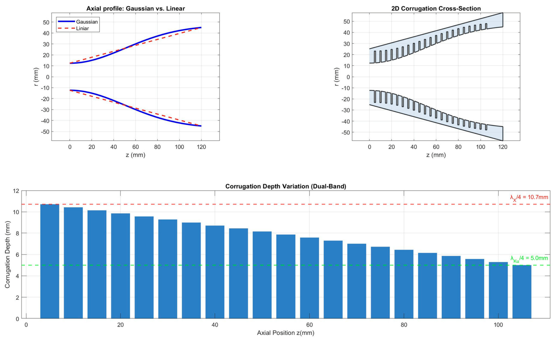
Using MATLAB, the mathematical expressions required to generate the Gaussian profile and determine the dimensions of the internal corrugations were defined. The antenna profile was generated in MATLAB, as shown in
Figure 1. The points generated by the program were then exported to a .dxf file compatible with Ansys HFSS. The file contains the 2D surface defining the corrugation dimensions and the variation of the normalized Gaussian profile. This surface was subsequently rotated through 360° about the generating axis to obtain the complete 3D antenna profile, after which the material properties and characteristics were assigned.
3. Antenna Design
A corrugated horn antenna can be defined as a conical horn antenna for which its walls consist of a periodic sequence of grooves oriented perpendicular to the propagation axis. The wall structure transforms the conducting surface into a reactive impedance surface, which imposes an identical boundary condition on the radial and azimuthal components of the electric field. As a result, the hybrid HE
11 mode is excited through a balanced combination of the TE
11 and TM
11 propagation modes, producing a symmetric radiation pattern, reduced sidelobe levels, and superior cross-polarization discrimination compared with smooth-wall horn antennas [
20].
To meet the requirements imposed by this study and achieve the objectives of the present work, the corrugated horn antenna was designed for simultaneous operation over the X-band and Ku-band within the overall frequency range of 7–15 GHz. As stated in
Section 2, the design employs a Gaussian geometric profile for the radius together with a linearly varying corrugation-depth scheme, extending from
at the input to
at the aperture. At the same time, modal balance is maintained over the entire dual-band operating range.
Considering the complete operating frequency range of 7–15 GHz, the antenna is intended to operate within the following uplink and downlink bands. The proposed antenna is designed for integration into a satellite communication system as a radiating element that can be installed onboard a satellite. The frequency bands of interest are the X-band, comprising 7.25–7.75 GHz for downlink and 7.9–8.4 GHz for uplink, and the Ku-band, comprising 10.7–12.75 GHz for downlink and 14–14.5 GHz for uplink.
The objective is to achieve coverage over these four frequency bands as extensively as possible, thereby supporting information transfer along the ground-to-space-to-ground communication path.
This section evaluates the main performance parameters of the designed corrugated horn antenna, including impedance matching over each operating frequency band, antenna gain, and circular polarization across the specified frequency ranges. In parallel, a comparative analysis is performed between the results obtained for the antenna designed with the empirically determined input radius, r
in =
= 7.5 mm, and those obtained using an input radius of r
in = 12.376 mm, calculated as a function of the waveguide cutoff frequency [
20].
The electromagnetic simulations were performed in Ansys HFSS using a driven-mode solution. Both antenna configurations were excited via a waveguide port defined at the smooth circular-waveguide feed section, with the number of modes set to 2 to capture the two degenerate orthogonal modes required for circular-polarization excitation; these two modes were subsequently combined during post-processing with equal amplitude and a 90° relative phase offset, as noted in
Section 5. The mesh was refined using an adaptive solution with up to six passes and a convergence criterion of Δ
< 0.02 between consecutive passes. The frequency response was computed using an interpolating sweep over the 7–15 GHz range, with results reported at 75 frequency points (≈107 MHz resolution). The computational domain was enclosed in an air region terminated by a radiation boundary, and the horn walls were modeled as a perfect electric conductor (PEC); conductor losses were therefore not included in the reported results.
4. Results
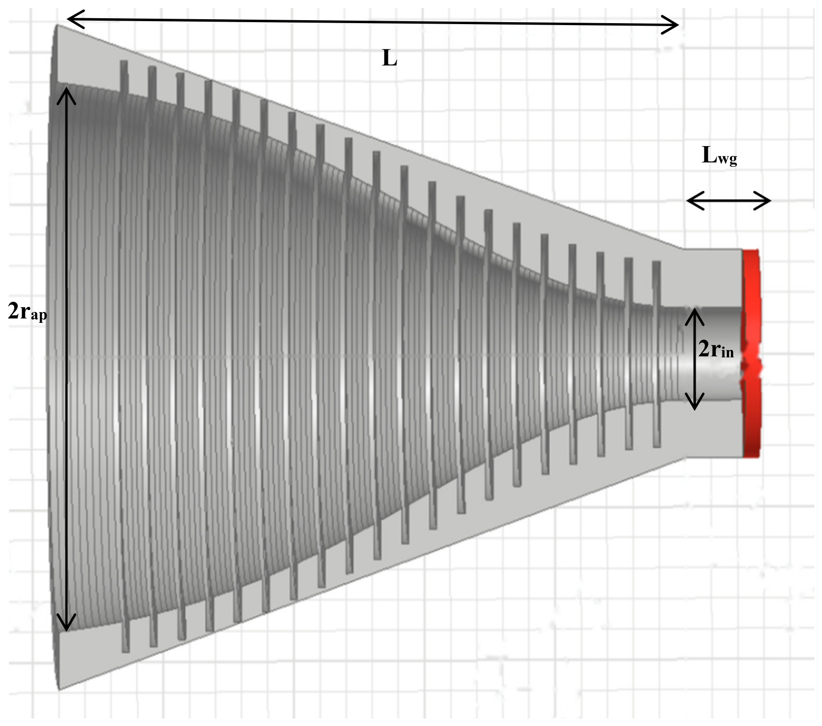
Following the calculation performed in the MATLAB simulation environment, the three-dimensional geometric profile of the corrugated horn antenna was obtained, as shown in
Figure 2. Two geometric configurations dependent on the input radius were investigated, with the corresponding geometric parameters presented in
Table 2.
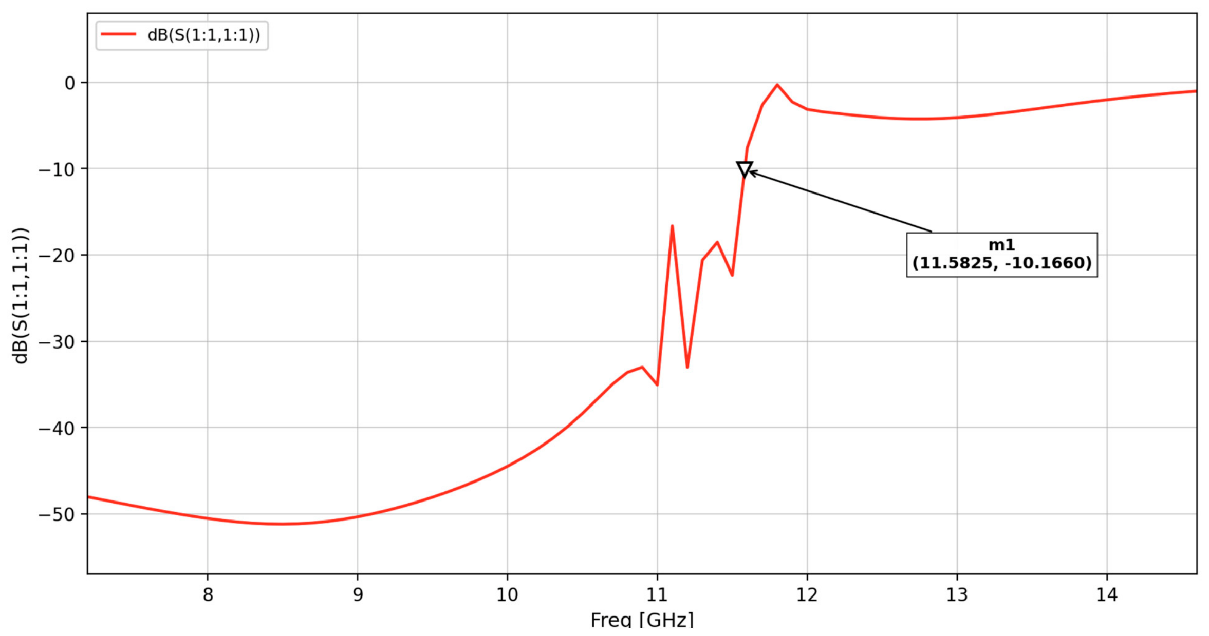
The first configuration considered was the antenna with an input radius defined empirically, as commonly used for circular smooth-wall horn antennas. The obtained results show impedance matching over the frequency range of 7–11.58 GHz, rather than over the entire desired operating bandwidth, as shown in
Figure 3. This range covers the uplink and downlink frequency bands corresponding to the X-band, together with the lower portion of the Ku-band downlink range, namely 10.7–11.58 GHz.
Based on these initial results, it can be stated that, when the input radius is not adapted to the modal propagation requirements (i.e., using the conventional empirical value rin = λ/4), the Gaussian-profile corrugated horn does not satisfy the requirements for dual-band operation, since the reflection coefficient S11 < −10 dB is not maintained over more than 75% of the Ku-band.
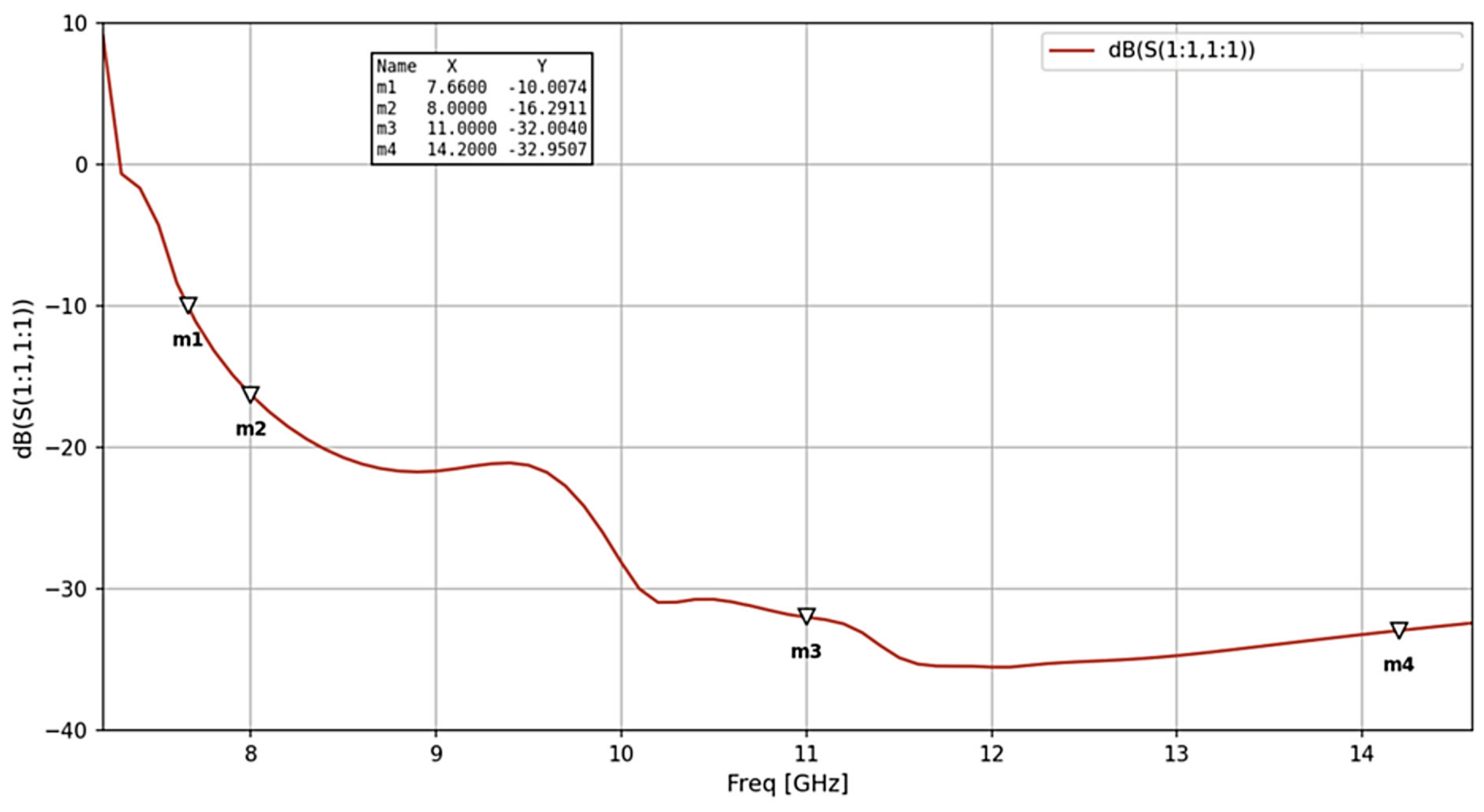
By developing the second antenna configuration, with the input radius calculated as a function of the wave propagation mode and the cutoff frequency, it can be observed that the antenna provides approximately 80% coverage of the proposed operating frequency range with S
11 < −10 dB, as shown in
Figure 4.
For the Ku-band, the uplink and downlink frequency ranges are characterized by the reflection coefficient of the proposed antenna as follows. The uplink band is covered by 100% within the frequency interval of 10.7–12.75 GHz, with an average S11 value of −33 dB, whereas the downlink band is covered by 100% within the frequency interval of 14.0–14.5 GHz, with an average S11 value of −33 dB.
The main limitation of this antenna configuration is related to the proximity of the lower operating band to the cutoff frequency, fcut = 7.0 GHz, where the reflection coefficient exhibits a steep downward slope. The lower edge of the 7 GHz frequency range is only approximately 1.4% above the cutoff frequency of the fundamental mode. Nevertheless, the reflection coefficient reaches a favorable value, providing coverage over a portion of the frequency band of interest. This result is attributed to the selection of the optimum input radius as a compromise between the two opposing modal constraints.
Based on the results presented in
Figure 3 and
Figure 4, the following paragraphs focus on the study and analysis of the Gaussian-profile corrugated horn antenna with an analytically determined input radius.
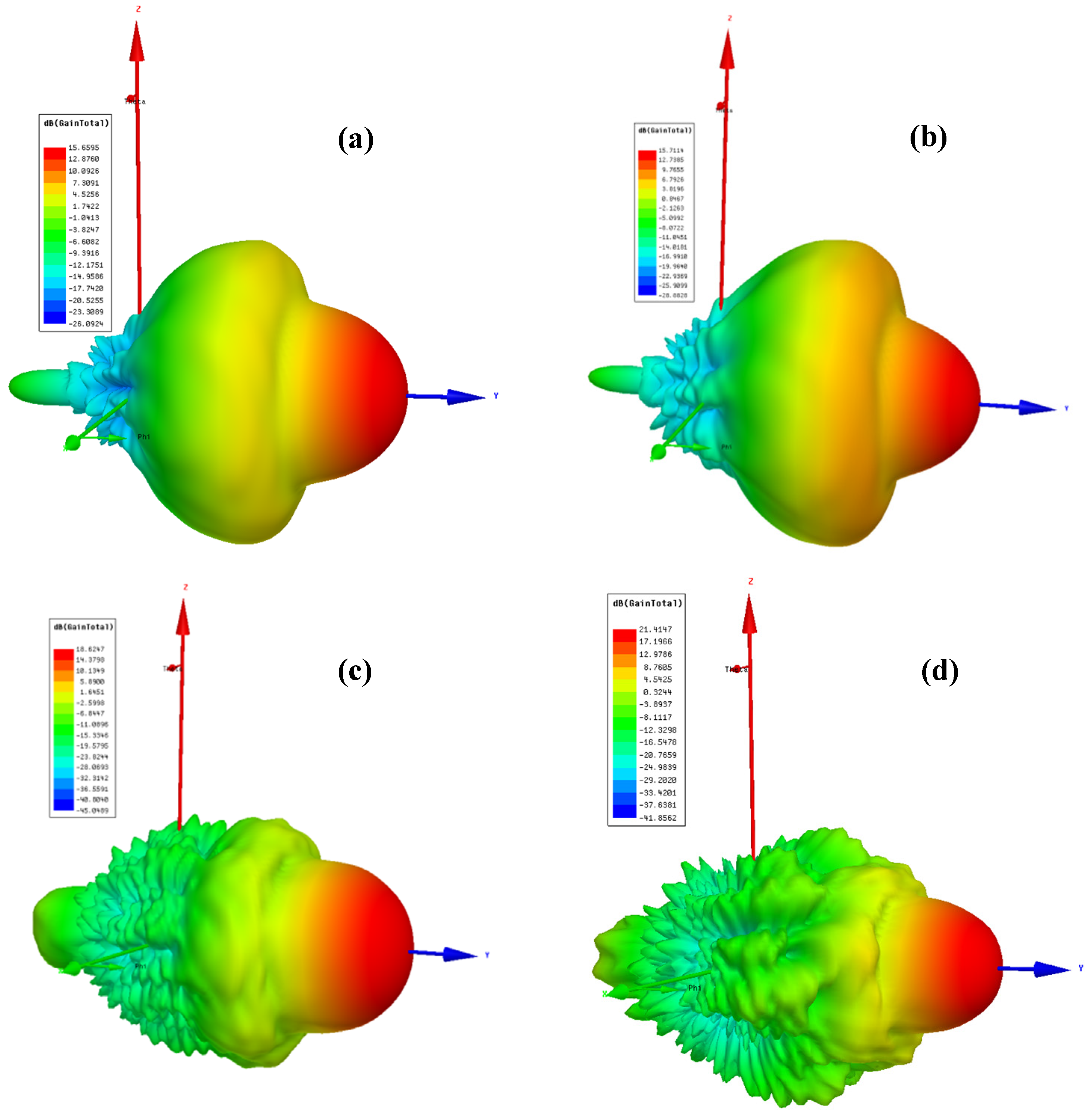
To enable a detailed analysis of the uplink and downlink frequency bands within the X-band and Ku-band, the antenna gain, beamwidth, aperture efficiency, and axial ratio (AR) with respect to the antenna polarization were evaluated at the four central frequencies corresponding to the specific uplink and downlink bands. Accordingly, 7.7 GHz corresponds to the X-band downlink, 8.2 GHz corresponds to the X-band uplink, 11.8 GHz corresponds to the Ku-band downlink, and 14.25 GHz corresponds to the Ku-band uplink.
As shown in
Figure 5, the antenna gain exhibits a monotonically increasing trend with frequency, ranging from 15.65 dB to 21.41 dB. This behavior is consistent with the increase in the electrical aperture size with frequency. The corresponding aperture efficiency ranges from 58.9% to 76.8%, which is in reasonable agreement with the theoretical values reported in the literature, typically ranging between 70% and 80% [
1,
2,
18].
The radiation patterns presented in
Figure 5 show that, as the operating frequency increases, the level of the main lobe increases, resulting in a higher antenna gain. At the same time, the sidelobes decrease in intensity and become more distinct and separated. In contrast, at the lower operating frequencies, the sidelobe distribution is more continuous around the main lobe and exhibits a higher intensity. This behavior reflects the frequency-dependent variation of the radiation pattern and is consistent with the increase in the electrical aperture of the antenna.
Typical corrugated horn antennas generally exhibit an aperture efficiency of approximately 70–80% and very low sidelobe levels, typically below −30 dB [
1,
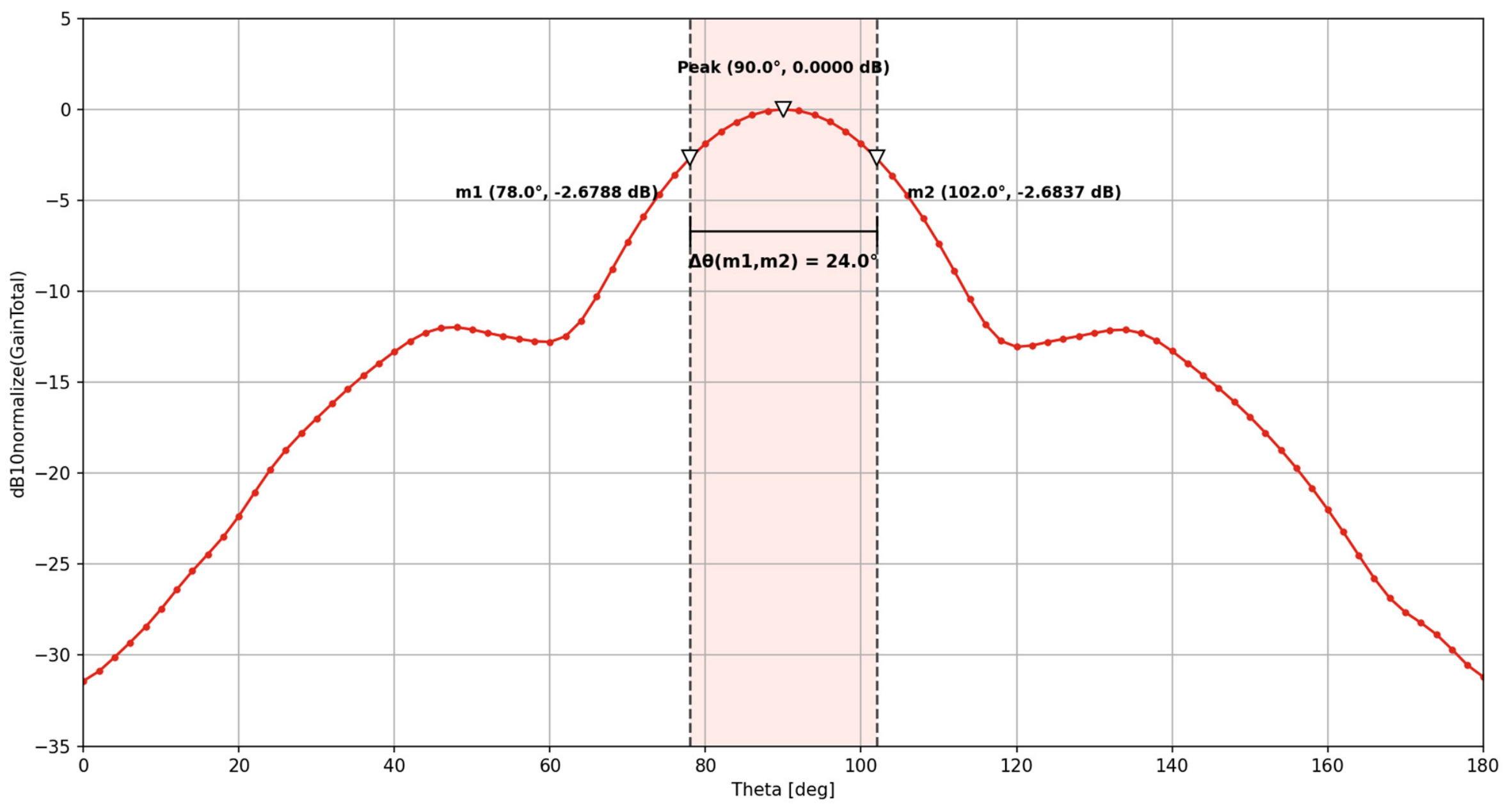
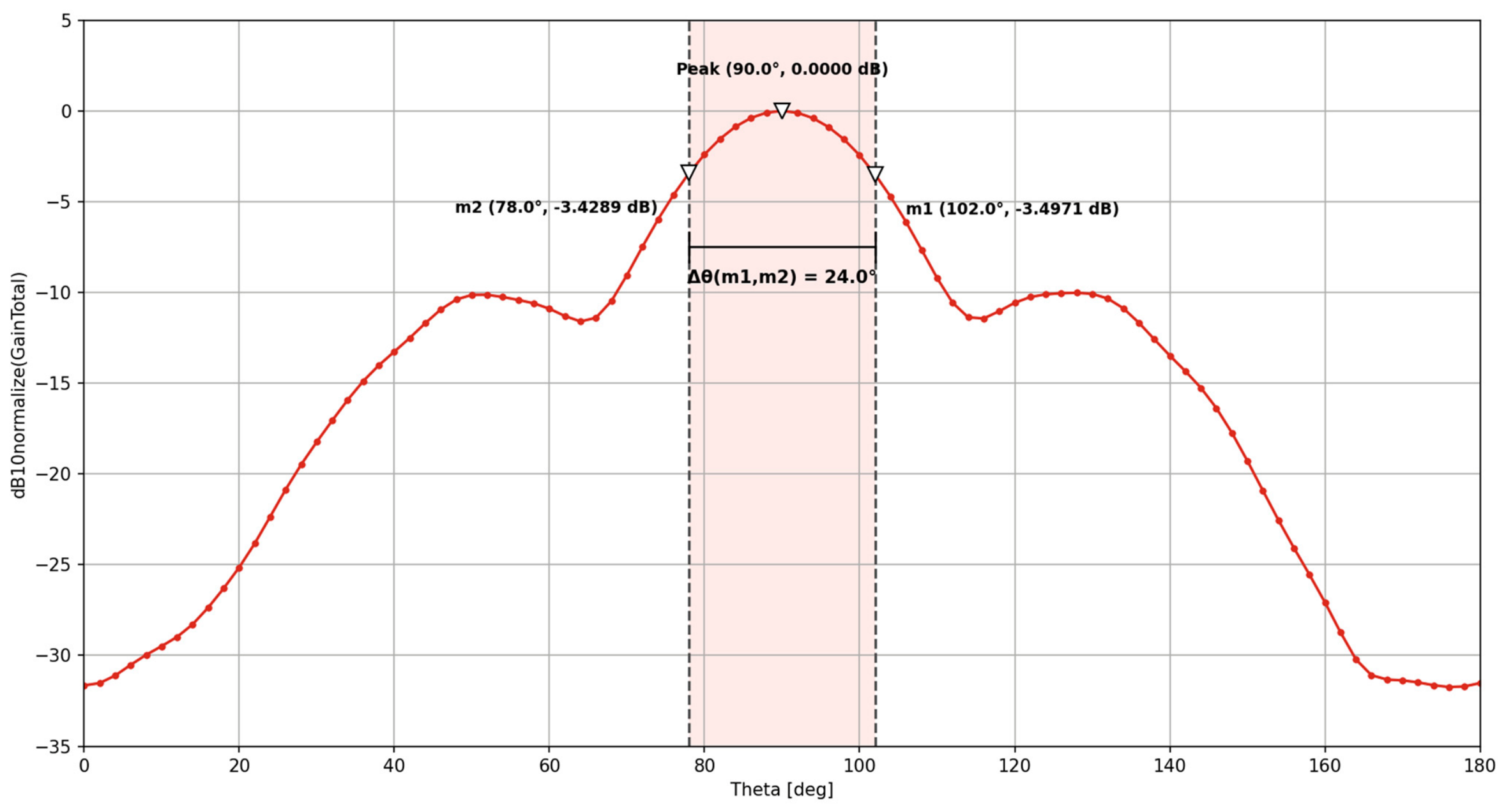
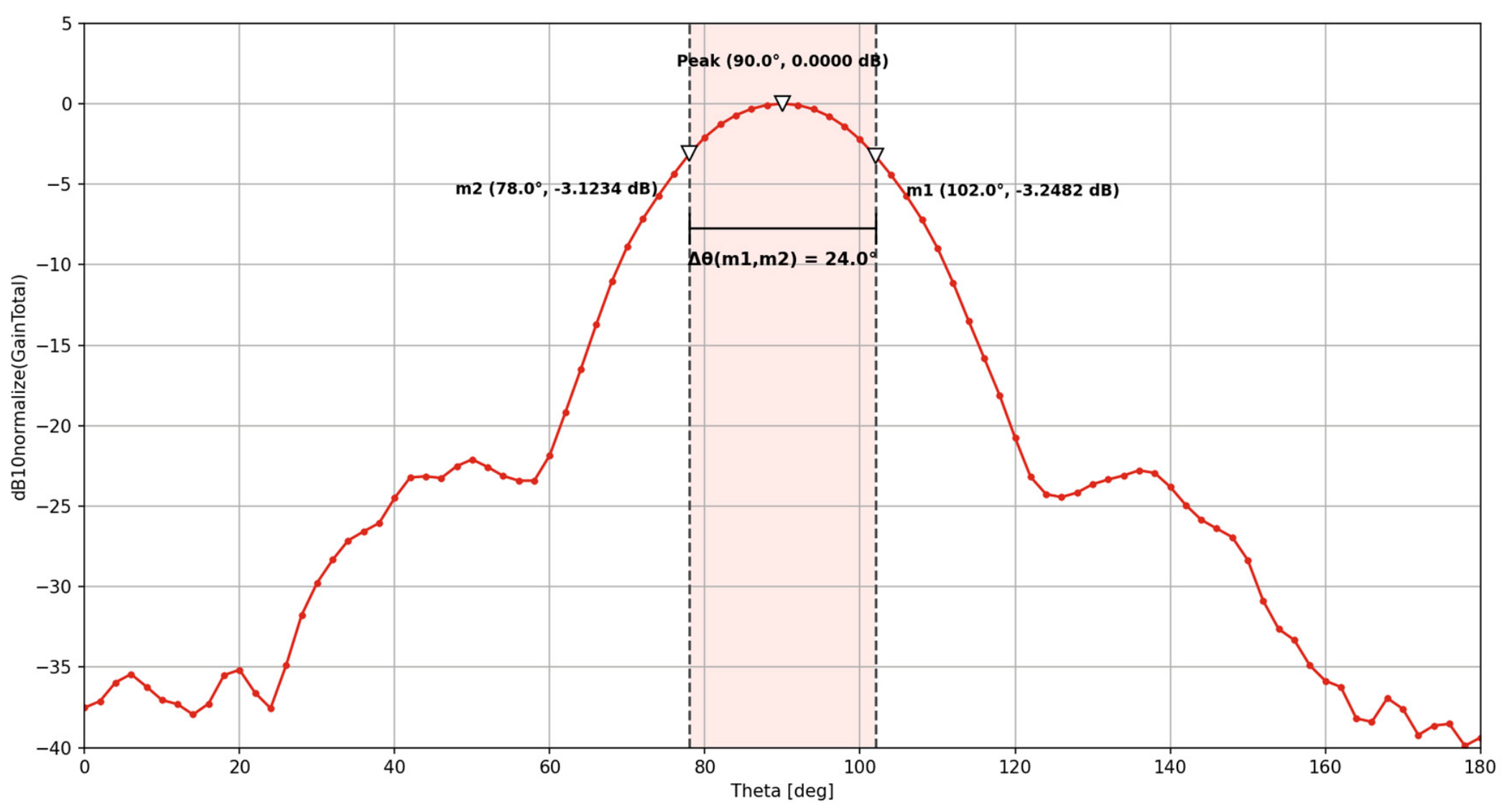
2]. The investigated antenna exhibits comparable performance, particularly within the Ku-band frequency range. Nevertheless, over the entire operating frequency range, the proposed antenna maintains a suitable gain while providing a relatively narrow beamwidth and sidelobe levels of approximately −12 to −13 dB, which is 12–18 dB higher than typical single-band Gaussian corrugated horns (below −25 dB [
1,
2]), as illustrated in
Figure 6,
Figure 7,
Figure 8 and
Figure 9. This trade-off is attributed to the wide corrugation-depth excursion (λ
X/4 to λ
Ku/4) required to bridge two widely separated bands within a single continuous profile, as discussed in
Section 2. The obtained results therefore represent a deliberate compromise between gain, beamwidth, and sidelobe level, favoring substantially wider dual-band coverage over the sidelobe performance achievable with a single-band design. The obtained results demonstrate a good compromise between antenna gain, beamwidth, and sidelobe suppression, indicating the suitability of the proposed corrugated horn antenna as a radiating element for satellite communication systems.
Analyzing
Figure 6,
Figure 7,
Figure 8 and
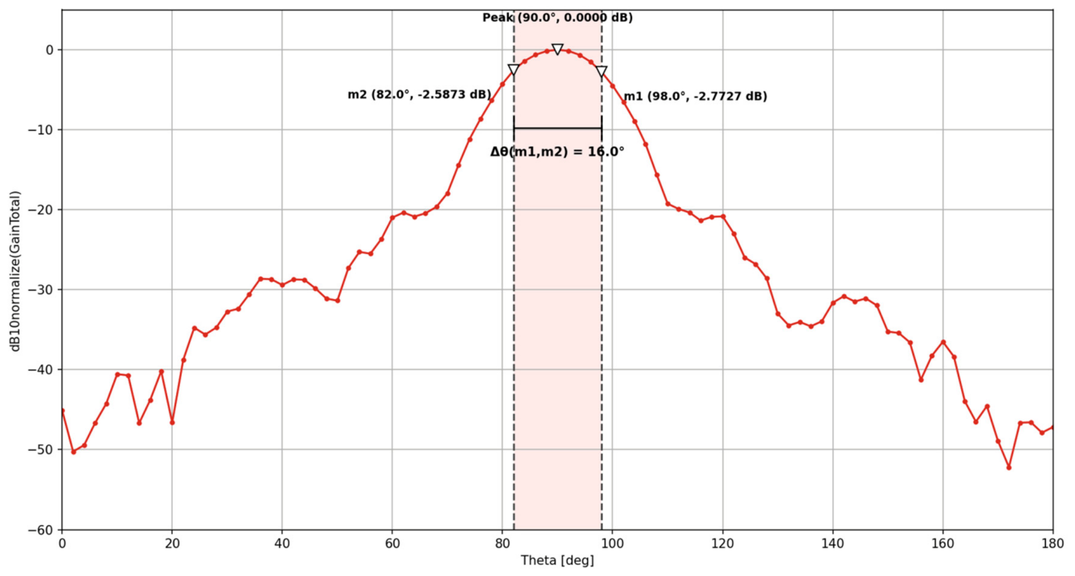
Figure 9, which present the beamwidth at each central frequency corresponding to the uplink/downlink bands, it can be observed that the investigated antenna exhibits a selective radiation pattern, with a difference of approximately 12–13 dB between the maximum of the main lobe and the maximum sidelobe level. This significant difference reduces the potential for interference caused by radiation in undesired directions. In contrast to the conventional behavior of a uniformly illuminated aperture, for which the HPBW decreases approximately inversely with frequency
[
18], the designed antenna maintains a half-power beamwidth of 24° across the three lower operating sub-bands (X-band downlink and uplink, Ku-band downlink), narrowing to 16° at the Ku-band uplink (14.25 GHz), exhibiting an HPBW ratio of 1.5:1 across this range. This is substantially more stable than the ≈1.85:1 narrowing predicted by uniform-aperture theory (HPBW ≈ 1/f) over the same frequency ratio, though it is not fully constant. This behavior can be attributed to the Gaussian profile employed in the antenna’s design [
21,
22].
As presented in
Table 3, the antenna gain exhibits an increasing trend with the operating frequency. The aperture efficiency at the lower and upper limits of the considered frequency range is consistent with the theoretical values reported in the literature. In contrast, a reduction in efficiency is observed toward the central region of the operating frequency range, which can be attributed to the specific Gaussian profile adopted for the corrugations and its influence on the aperture field distribution [
21]. The −3 dB beamwidth, or half-power beamwidth (HPBW), remains at approximately 24° for the first three uplink/downlink frequency bands. For the Ku-band uplink frequency, however, the HPBW decreases to approximately 16°, indicating a narrower main radiation lobe at the highest operating frequency.
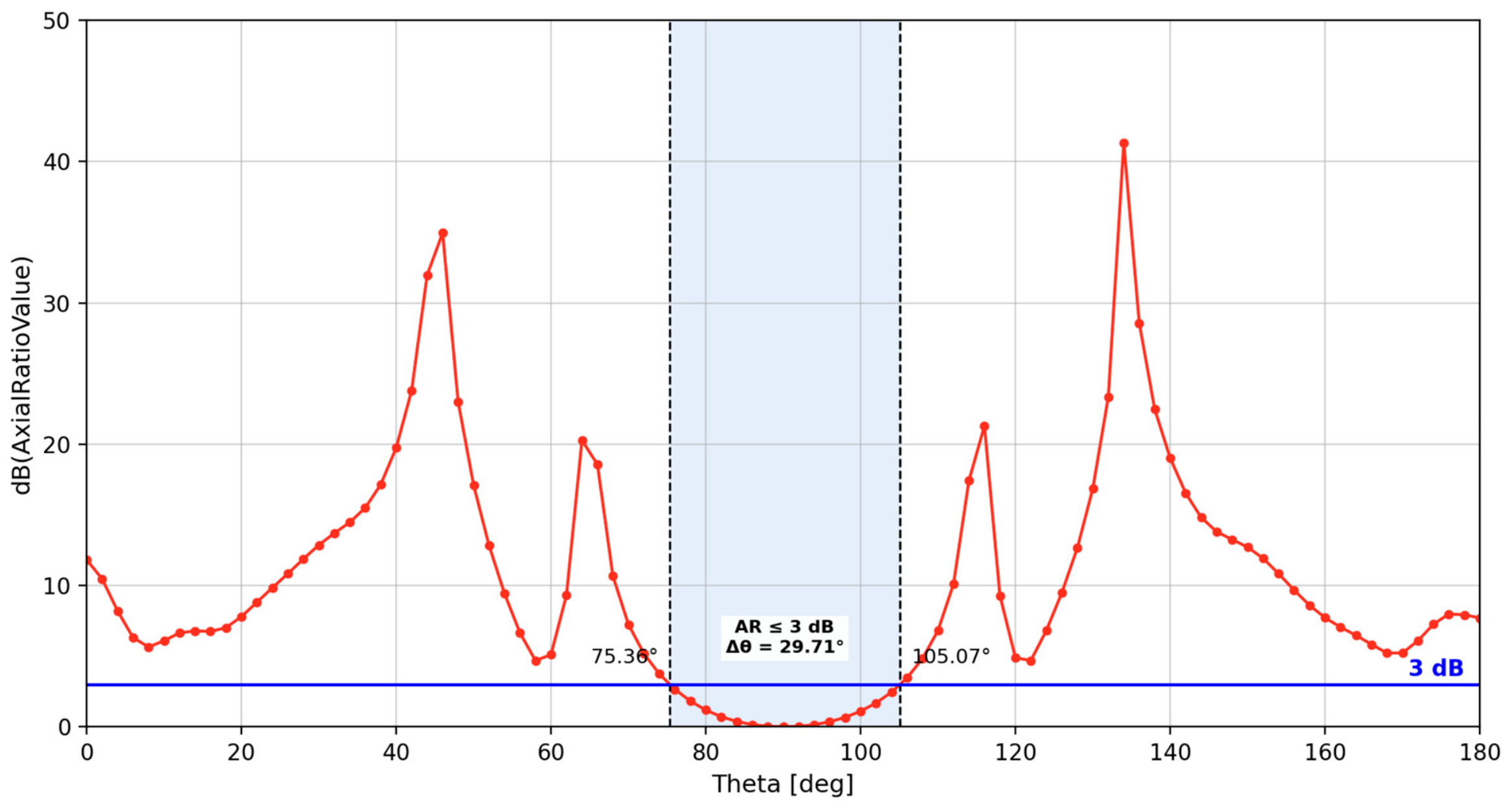
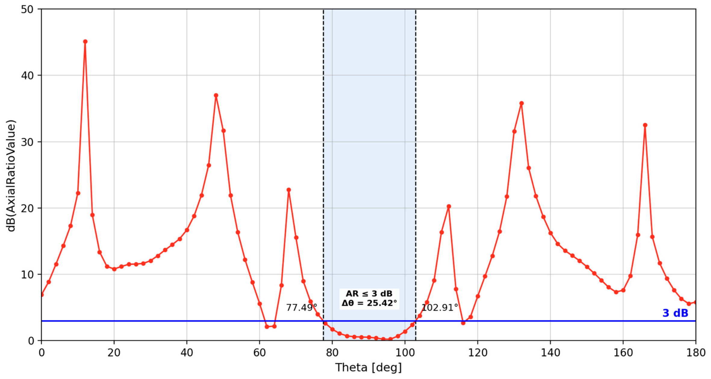
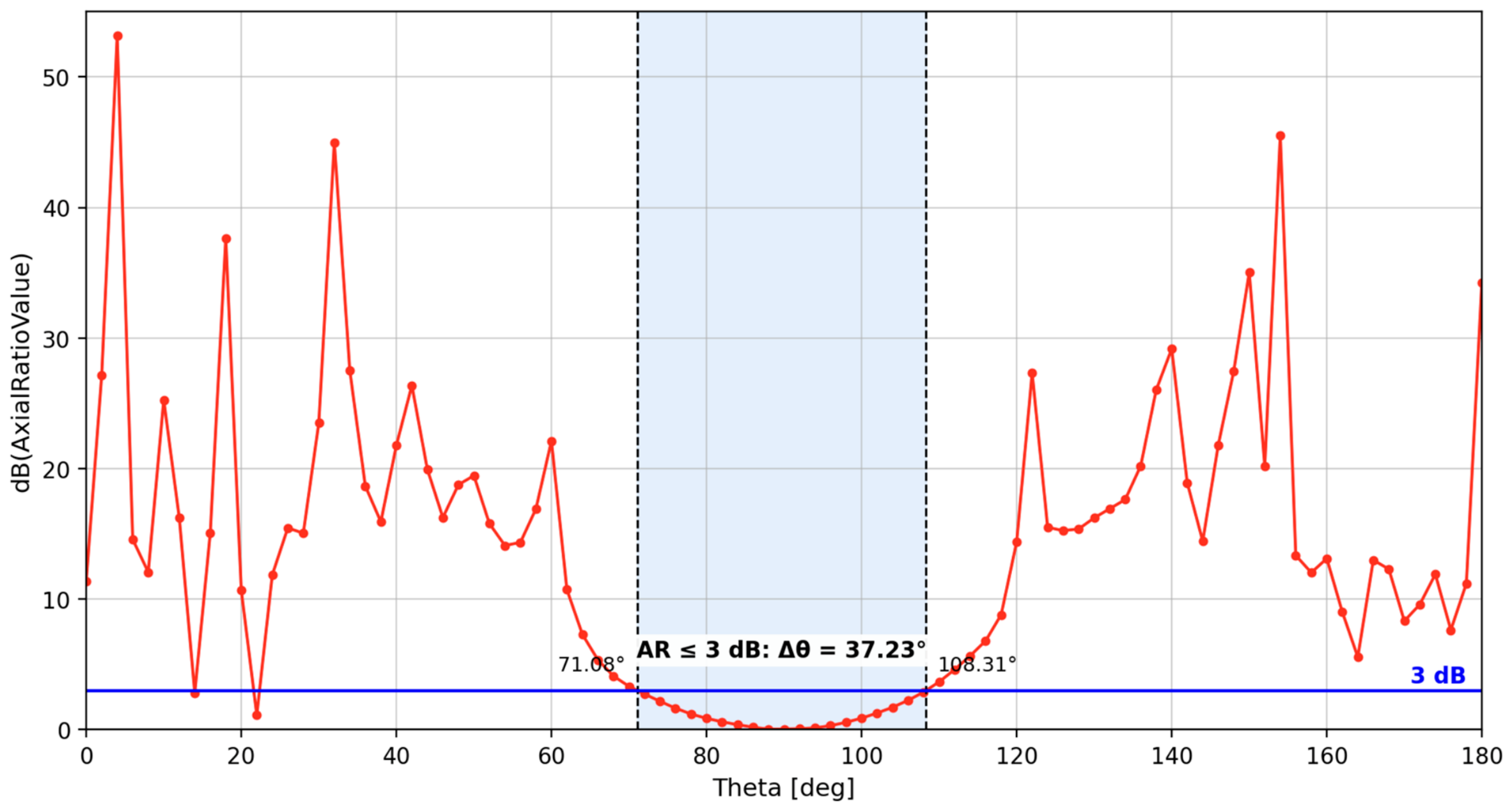
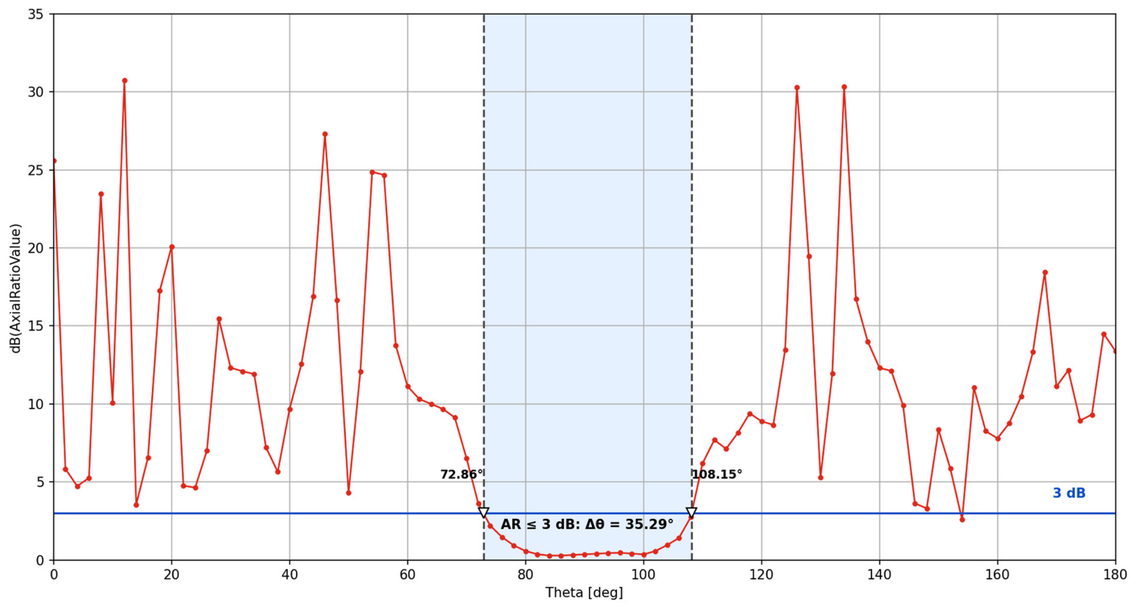
The axial ratio analysis presented in
Figure 10,
Figure 11,
Figure 12 and
Figure 13 indicates the achievement of circular polarization in the vicinity of the maximum radiation direction. The region satisfying the circular polarization criterion extends beyond the HPBW by a factor ranging from 1.06 to 2.21, depending on the operating frequency. Circular polarization is obtained through the simultaneous excitation of the two degenerate hybrid modes at the waveguide port with a 90° phase difference [
22]. The results indicate that the circular polarization condition is maintained over a significant portion of the useful radiation pattern and is not restricted to the direction of maximum radiation.
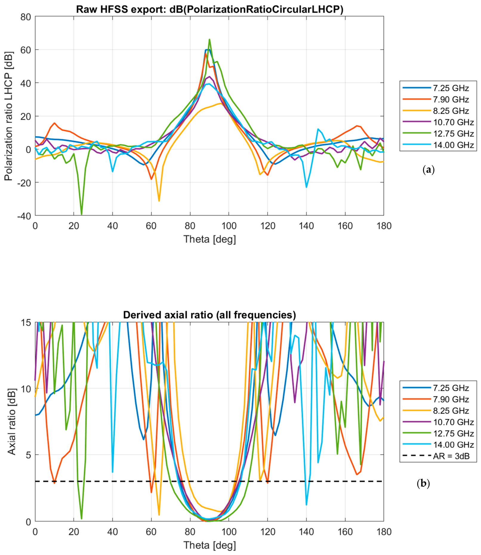
To further characterize the broadband circular-polarization performance, the boresight axial ratio was evaluated as a continuous function of frequency. For each frequency, AR was obtained from the same validated far-field angular sweep used for
Figure 10,
Figure 11,
Figure 12 and
Figure 13 by extracting the LHCP/RHCP polarization ratio (PR in dB) at the boresight direction (θ = 90°) and via the standard relation AR(dB) = 20 log
10[(1 + r)/|r − 1|], where r = 10
(|PR|/20) [
18]. This approach reuses the same validated excitation and far-field configuration as
Figure 10,
Figure 11,
Figure 12 and
Figure 13 rather than a direct frequency-swept axial-ratio report. Across the six evaluated frequencies, the boresight axial ratio remained below 1 dB in every case (0.01–0.93 dB), with the AR < 3 dB angular window ranging from 23.8 to 40.3°, confirming that the circular-polarization performance is maintained consistently across the operating band rather than only at the four previously reported center frequencies (
Figure 14).
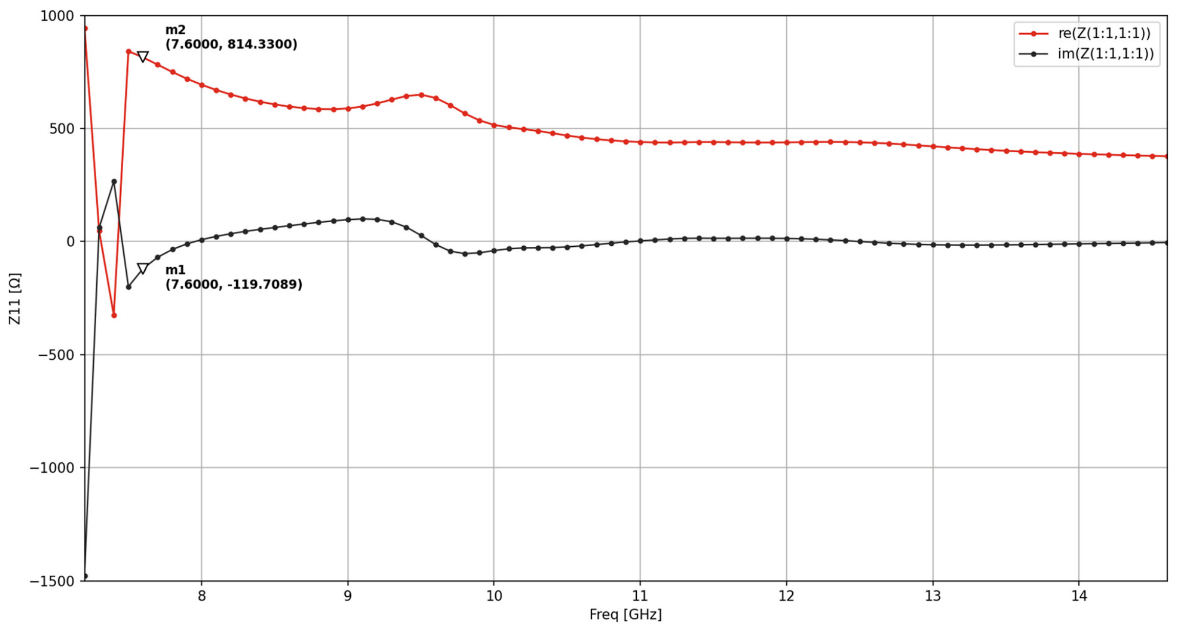
The variation of the waveguide port characteristic impedance confirms the occurrence of a modal transition in the vicinity of the analytically determined cutoff frequency (
Figure 15). The real part of the impedance exhibits an abrupt discontinuity, while the imaginary part indicates the transition of the mode from the evanescent regime to the propagating regime [
16]. Beyond this deviation observed at the lower limit of the operating frequency range, the characteristic impedance exhibits a stable behavior above 7.6 GHz, indicating the establishment of a well-defined propagation regime for the fundamental mode over the remainder of the operating band.
5. Discussion
To provide a comprehensive assessment of the studied antenna and to separately address the trade-offs and comparative analyses that formed the basis for selecting the next stage in the development and design of the Gaussian-profile corrugated horn antenna, several aspects identified throughout this study will be discussed separately. For the analysis of the antenna geometries defined according to the variation of the antenna’s input radius, it can be stated that the geometry calculated based on the propagation mode and cutoff frequency completely eliminates the impedance mismatch observed in the first case, as shown in
Figure 3, over the frequency interval of 11.58–15 GHz. This mismatch was expected for the empirically determined antenna geometry, since the increasing slope of the reflection coefficient occurs around 11.75 GHz, which is close to the cutoff frequency of 11.72 GHz corresponding to the input radius r
in =
= 7.5 mm.
It can be observed that the empirically defined geometry exhibits a severe degradation of the reflection coefficient in the vicinity of 11.6 GHz. This behavior can be attributed to the divergence of the characteristic impedance of the TE11 propagation mode as the cutoff frequency is approached, with fcut = 11.72 GHz for the considered radius. In contrast, the analytically recalculated geometry, obtained by balancing the propagation condition of the first higher-order mode having the same azimuthal symmetry, TM11 completely eliminates this degradation over the 11.58–15 GHz interval. In this case, the reflection coefficient S11 remains approximately constant at around −30 dB.
The comparison between the S
11 results presented in
Figure 3 and
Figure 4 highlights the direct influence of the adopted dimensioning criterion on the antenna impedance-matching performance. The values obtained for each frequency band of interest are presented in
Table 4. For the empirically designed antenna, the reflection coefficient increases significantly beyond the −10 dB limit, starting at approximately 11.6 GHz. In contrast, for the analytically calculated geometry, the reflection coefficient remains stable at approximately −32 dB over 75% of the considered operating bandwidth.
For the Gaussian-varying profile, no corrugation is exactly optimized for both frequency bands simultaneously, with the corrugations located in the central region of the profile being sub-optimal for both frequencies of interest. This behavior is consistent with the theoretical prediction formulated in
Section 2. The results presented in
Table 3 quantitatively confirm this prediction: The minimum illumination efficiency of 58.8% is obtained precisely in the bands at the lower and upper extremes of the interval (7.25–7.75 GHz and 14–14.25 GHz), while the intermediate bands achieve higher efficiencies of 69.9% and 76.7%, respectively. This correspondence between the geometric mechanism identified analytically and the behavior observed in the simulations confirms the validity of the proposed theoretical model for the design of the variable-depth corrugated profile.
When comparing the performance of the proposed antenna with that of similar antennas reported in the literature, an expected trade-off can be observed between spectral coverage and peak performance for individual parameters, as presented in
Table 5. The antenna developed by Teniente et al. for the HISPASAT 1C/1D satellite achieves higher cross-polarization discrimination and very good impedance matching, comparable to that of the proposed antenna. However, it operates in a single band over the relatively narrow frequency range of 11.7–12.2 GHz, representing a considerably simpler design scenario than that considered in the present study, where dual-band operation is achieved over the 7–15 GHz frequency range.
Although the proposed antenna covers a significantly wider operating bandwidth and requires more complex design considerations, with the associated performance trade-offs being carefully balanced, its results remain comparable to those reported by Teniente et al. The ridged hybrid antenna proposed by Manshari et al. covers a wide frequency range and achieves a gain between 12 and 18 dB, demonstrating the feasibility of dual-band operation using a continuous structure. However, this solution employs a considerably more complex geometry than the antenna investigated in the present study, while providing comparable performance.
The antenna developed in the present work achieves higher gain and very good impedance matching over most operating bandwidths while employing a simpler geometric structure without additional sections. As also indicated in
Table 5, this comparison shows that the continuous Gaussian profile represents a viable alternative in terms of structural complexity to extended hybrid solutions, while providing comparable or improved gain and impedance-matching performance.
Based on the results obtained in
Section 3, it can be stated that the selection of such a wide operating frequency range, intended to cover the entire uplink and downlink bands of interest, introduces several minor limitations of the studied antenna. One example is the discontinuity observed in the lower part of the operating band, where the cutoff frequency is also located. This condition leads to a divergence of the propagation mode, affecting the impedance matching of the antenna within the downlink portion of the X-band and reducing the effective downlink bandwidth by approximately 0.5 GHz.
The main novelty of this study lies in the design of a corrugated horn antenna capable of dual-band operation while simultaneously providing performance characteristics suitable for implementation in satellite communication systems, such as high selectivity, high gain, and circular polarization. Another novel aspect of this study is the comparative analysis between a Gaussian-profile corrugated horn antenna for which its dimensions are determined using empirical numerical values derived from the study of conventional horn antennas and a Gaussian-profile corrugated horn antenna for which its geometry is determined analytically according to the propagation modes and cutoff frequency.
Considering that the objective of this study is to develop and experimentally validate the final antenna configuration in the laboratory, an additional limitation may arise during practical implementation. Specifically, the experimental validation of the designed antenna requires an appropriate feeding configuration, involving internal coaxial probes integrated into the smooth-wall waveguide and positioned with high dimensional accuracy. However, the generation of circular polarization requires a configuration capable of introducing a 90° phase difference between the orthogonal modes. Therefore, an external quadrature hybrid coupler will be required [
23], serving as the physical equivalent of the bimodal excitation employed in the electromagnetic simulations.
In view of the practical realization of the studied antenna, several sources of manufacturing error can be estimated analytically. For the input radius, solving fc = pc/2πr for the radius at which each cutoff frequency would reach the nearest actual operating sub-band edge gives rlimit(low) = p(TE11)GHz = 12.126 mm and rlimit(lhigh) = p(TM11) GHz = 12.617 mm, corresponding to an admissible error of −0.252 mm/+0.239 mm around ropt before either cutoff intrudes into the X-band downlink or Ku-band uplink, respectively, a budget substantially larger than typical CNC tolerances (±0.02–0.05 mm). The corrugation period (p = 5 mm) similarly retains a 33% margin below the λmin/3 grating-lobe threshold. For circular polarization, decomposing the two orthogonal feed excitations into their RHCP/LHCP components shows that the axial ratio equals the feed amplitude imbalance (in dB) exactly at zero phase error and remains below 1.3 dB for representative quadrature-hybrid tolerances (0.5–1 dB, 3–5°), well within the 3 dB requirement. In contrast, the corrugation depth cannot be bounded analytically in the same way: Since each groove behaves as a short-circuited stub with input reactance Zin = jZ0tan(βd), where β = 2π/λ, the nominal design depth coincides with the pole of this function, where the ideal-stub model predicts unbounded sensitivity to small deviations. Quantifying the actual, finite sensitivity of the real corrugated structure therefore requires a dedicated HFSS parametric sweep of depth (±0.05–0.1 mm), proposed here as part of the future experimental validation work.
6. Conclusions
The present manuscript aims to investigate a satellite communication antenna that can serve as the radiating elements of a reflector onboard a satellite system, with the purpose of transmitting information to an unmanned aerial vehicle (UAV). The normalized Gaussian-profile corrugated horn antenna is designed to provide dual-band performance across the X-band and Ku-band, covering the 7–15 GHz frequency range and, implicitly, the four uplink/downlink frequency bands of interest. These frequency bands are intended to support communication between the receiver and transmitter within the UAV–satellite–UAV communication link.
Based on the analysis of the reflection coefficient, it was demonstrated that, for a wideband antenna intended to provide dual-band operation, analytical calculations based on the propagation-mode behavior within the waveguide and its cutoff frequency are required. This aspect is also demonstrated by the results presented in
Figure 3 and
Figure 4 and
Table 4.
This study demonstrated that the input radius of a normalized Gaussian-profile corrugated horn antenna, derived from a minimax criterion balancing the modal propagation conditions and the cutoff frequency, substantially reduces the limitations associated with the conventional empirical approach (rin = λ/4). The direct comparison between the two geometries, identical in structure and differing only in their input radius (7.5 mm for the empirical design versus 12.376 mm for the analytically calculated compromise radius), confirmed that the selection of the compromise radius, which equally balances the propagation margins of the TE11 and TM11 modes, is the determining factor for achieving wideband impedance matching.
The proposed antenna operates simultaneously across the X-band and Ku-band (7–15 GHz), covering the four uplink/downlink sub-bands of interest for satellite communications. The obtained gain ranges from 15.5 dB to 21.41 dB across the four central frequency bands, with an illumination efficiency between 58.8% and 76.7%. Circular polarization is maintained over an angular region exceeding the −3 dB beamwidth, with an axial ratio below 3 dB across each frequency band of interest.
From the perspective of the selectivity of the investigated antenna, beamwidth stabilization across the entire operating bandwidth has also been documented in the specialized literature for dual-band corrugated horn antennas. The beam shape and main-lobe width remain relatively consistent over the entire frequency range, exhibiting a behavior comparable to the results obtained in the present study [
22]. Circular polarization is consistently maintained across the uplink and downlink bands, with an axial ratio below 3 dB, as shown in
Figure 10,
Figure 11,
Figure 12 and
Figure 13, over an extended angular region beyond that defined by the HPBW. Consequently, the antenna provides radiation and polarization characteristics suitable for GNSS applications.
Unlike prior variable-depth designs, which vary depth only over a short transition zone for single-band operation [
17] or achieve broadband coverage through additional structural sections, such as ridges or coaxial diplexers [
8,
9,
10], the present design uses a single continuous analytic function governing the corrugation depth over the entire horn length, engineered specifically to bridge two widely separated bands (2.14:1 ratio) without any discrete zones or external components. This configuration constitutes the principal novelty of the proposed design, together with the systematic comparison between empirical and analytical dimensioning applied to the same reference geometry. Compared with the Chocked Gaussian antenna reported by Teniente et al., which achieves an XPD greater than 40 dB and a gain exceeding 18.36 dB over the single-band range of 11.7–12.2 GHz, and the corrugated-rib hybrid antenna reported by Manshari et al., which provides a gain of 12–18 dB over 6–20 GHz at the expense of a more complex geometry, the investigated antenna achieves comparable or improved gain and impedance-matching performance over the 7–15 GHz dual-band range, while maintaining a simpler geometric configuration without additional structural sections.
The results presented in this study are based exclusively on electromagnetic simulations performed using Ansys HFSS, with experimental validation representing a necessary subsequent stage. A limitation is observed in the vicinity of the cutoff frequency (fcut ≈ 7.0–7.1 GHz), where the modal divergence of the fundamental mode influences the impedance matching in the lower-frequency region of the X-band. The physical implementation of the feeding system, based on precisely positioned coaxial launchers, and the generation of circular polarization through an external quadrature hybrid coupler represent additional design aspects requiring further investigation for the realization of a functional prototype. Future work will address the fabrication of a prototype and the experimental validation of the reflection coefficient, gain, and circular polarization characteristics, together with the practical integration of the coaxial launcher and external hybrid coupler into a final antenna configuration intended for satellite-system implementation.