Article

Feasible-Region-Based Limit Analysis and Adaptive LVRT Control of Grid-Forming VSGs in Weak Grids

School of Electronic and Electrical Engineering, Lingnan Normal University, Zhanjiang 524048, China
*
Author to whom correspondence should be addressed.
Electronics 2026, 15(17), 4029; https://doi.org/10.3390/electronics15174029
Submission received: 27 June 2026 / Revised: 25 July 2026 / Accepted: 6 August 2026 / Published: 6 September 2026

Abstract

This paper proposes an adaptive low-voltage ride-through (LVRT) control framework for grid-forming virtual synchronous generators (VSGs) in weak and ultra-weak grids based on feasible-region and fault ride-through limit-boundary analysis. The proposed method achieves coordinated active–reactive power regulation during fault conditions and enhances the fault ride-through capability and synchronization stability of the system. First, an equivalent voltage-vector decomposition is used to establish the fault-stage operating model of the VSG, based on which the feasible active–reactive power region is characterized under current, line-reactance, and apparent-power constraints. Then, the maximum active power transfer capability, maximum reactive power support capability, and critical voltage-sag boundary are derived by considering both current limitation and power-angle stability. Furthermore, unlike existing feasible-domain-based methods that mainly focus on voltage-command limitation, a unified power-circle–capability-cone constraint model is developed to directly generate feasible active–reactive power references within the original VSG framework. A voltage-dependent adaptive droop coefficient is introduced to dynamically coordinate active and reactive power allocation, thereby enlarging the feasible LVRT region and improving the stability margin. Finally, a distributed consensus mechanism is designed to coordinate active and reactive power references among multiple VSGs within their feasible regions and suppress fault-induced power oscillations. Simulation results verify that the proposed method enhances voltage support, expands the feasible LVRT operating region, suppresses power and power-angle oscillations, and improves transient stability under weak-grid conditions.

1. Introduction

The large-scale integration and long-distance transmission of renewable energy have exacerbated issues such as extended transmission lines, weak grid structures, and insufficient support from conventional thermal power units, so power systems increasingly exhibit weak or ultra-weak grid characteristics [1]. Under these conditions, a voltage sag may cause large-scale renewable generation units to trip and potentially trigger voltage instability, frequency instability, or cascading failures. Therefore, grid-connected devices must have reliable low-voltage ride-through (LVRT) capability [2,3]. However, conventional grid-following (GFL) control strategies, which rely on current-source characteristics, have inadequate performance during voltage sags and frequency fluctuations, which often results in insufficient voltage support and limited frequency regulation and threatens the secure, stable operation of the system [4].
In recent years, grid-forming (GFM) control technologies have attracted significant research attention. Among them, the virtual synchronous generator (VSG) strategy emulates the inertia and damping characteristics of synchronous machines, thereby providing virtual inertia and frequency support. Moreover, it can provide voltage support capability and disturbance rejection performance under weak and ultra-weak grid conditions, and is therefore regarded as an effective approach for improving system stability [5,6,7]. However, the performance of GFM/VSG control is highly sensitive to grid strength. Although oscillatory behavior may arise in strong grids due to interactions with stiff voltage sources, in practical renewable integration scenarios, weak and ultra-weak grids pose more severe challenges, particularly during fault conditions. Specifically, under low short-circuit ratio (SCR) conditions, the limited short-circuit capacity leads to deeper voltage sags, reduced power transfer capability, and stricter current constraints, thereby significantly increasing the risks of overcurrent, loss of synchronism, and failure of fault ride-through (FRT) [8]. Therefore, it is necessary to develop enhanced LVRT strategies based on the conventional VSG control framework. Such strategies should maintain voltage-source characteristics under current constraints while achieving coordinated control of voltage support and rotor-angle stability, thereby improving the robustness and stability of power systems under weak and ultra-weak grid conditions.
To enhance the FRT capability of VSG-based GFM technologies, existing studies have primarily focused on two aspects: large-disturbance modeling and control strategy improvement. Prior studies developed large-disturbance models of conventional GFL converters in the case of symmetrical grid faults to analyze the converter stability [9,10]. These studies also qualitatively examined the equilibrium between active power reference curves and network characteristic curves. The research revealed that the FRT instability likely occurred under ultra-weak grid conditions. Based on this finding, researchers proposed several improvement strategies in four categories: mode-switching, conventional FRT, voltage-source-type FRT, and current saturation control. 1. Mode-switching strategies: In these methods, the GFM control is switched to GFL control during fault conditions, such that current limiting and voltage support can be achieved through the internal current loop. Representative approaches include balanced current control (BCC) and constant active power control (CAPC). Although fault currents can be effectively suppressed by these strategies, the grid-forming characteristics of the VSG are lost, and the capability for inertia and voltage support can no longer be maintained. In addition, the switching process is typically implemented with the aid of an additional phase-locked loop (PLL), by which instability can easily be introduced under weak-grid conditions, and transient disturbances may be caused during mode transitions [11,12]. To address this issue, negative-sequence current regulation has been incorporated in some studies while the positive-sequence VSG control has been retained, such that the objectives of BCC/CAPC and the positive-sequence GFM characteristics can be simultaneously achieved [13]. However, most existing methods have been validated under strong-grid conditions, and their applicability to ultra-weak grids has not yet been fully verified. 2. Conventional FRT strategies based on PQ reference regulation: These methods mainly achieve overcurrent suppression and voltage support by enhancing reactive power–voltage droop control and optimizing active–reactive power coordination. Essentially, these methods belong to PQ-controlled VSG-based FRT strategies, whose core principle is the dynamic adjustment of active and reactive power references without significantly modifying the overall control structure [14]. 3. Voltage-source-type FRT strategies: These approaches calculate the active references, voltage commands, and virtual impedance based on the fault voltage sag depth and equivalent system impedance to maintain the rotor-angle stability and limit the short-circuit current. They can reduce the phase deviation between VSG output and grid voltage during faults and consequently improve the transient stability. However, the high computational complexity limits their practical applicability in engineering scenarios [15,16]. 4. Current saturation control strategies: Because the fault current tolerance of VSGs is inherently limited (typically 1.2–2.0 pu.) [3,17,18], these strategies maintain a constant saturation value to avoid transient overcurrent caused by reference disturbances or mode switching. The current saturation methods can be further classified into hardware-based [19,20] and software-based solutions. Hardware-based solutions, such as fault current limiters and compensators, effectively restrict the current but suffer from high cost and limited engineering feasibility. In contrast, software-based solutions are more flexible and can be directly embedded into the controller. Typical implementations include reducing the voltage command using a virtual impedance or coordinating the active–reactive power distribution to limit the current [21]. Nevertheless, these strategies often continuously saturate the outer voltage loop, which requires virtual power to maintain synchronization. This virtual power may result in desaturation failures after fault recovery and restrict applicability in high-voltage ride-through and consecutive FRT scenarios [22,23].
Currently, research on the FRT capability of VSGs under ultra-weak grid conditions remains relatively limited. Reference [1] proposed an enhanced FRT strategy based on a GFM characteristic model and a feasible fault domain definition, where dynamic voltage limiting was introduced to improve the coordination between current limitation and voltage support. However, this study was confined to single-machine simulations and lacked multi-machine coordination analysis. Reference [24] addressed the power oscillations in the recovery stage of conventional FRT by introducing an adaptive virtual resistance strategy, which was robust in both weak and ultra-weak grid conditions. Reference [21] proposed an adaptive FRT method for three-phase four-wire VSGs to integrate an instantaneous saturator, an adaptive virtual negative-sequence resistance, and a zero-sequence resistance, which suppressed the overvoltage and overcurrent in various fault scenarios. However, its reliance on the real-time grid parameter estimation during faults limits engineering applicability. Overall, these approaches enhance the LVRT performance in ultra-weak grids, but they cannot sufficiently adapt to multi-VSG operation, complex disturbances, and extreme fault conditions. Prior studies further indicated that when multiple VSGs operated in parallel, insufficient mutual damping might induce power oscillations, amplify the fluctuations during FRT, potentially endanger the system stability, and undermine the reliable ride-through performance [25].
In summary, different FRT strategies have different control objectives, implementation complexities, and applicable scenarios. Therefore, this paper does not aim to demonstrate the universal superiority of the proposed method over all existing FRT strategies. Instead, it focuses on improving the conventional PQ-reference-based FRT framework. This type of strategy preserves the original voltage-source control structure of the VSG, requires only modifications to the outer power-reference loop, and can be readily extended to multi-VSG coordination scenarios.
However, under extremely weak-grid conditions, the point of common coupling (PCC) voltage cannot accurately reflect the system power transfer limit, making it difficult to coordinate current constraints, synchronization stability, and active-power references. In addition, fault disturbances may aggravate power oscillations in multi-VSG systems and reduce the overall system stability. To address these issues, a feasible-region-constrained adaptive LVRT and multi-VSG coordinated control strategy is proposed in this paper. The main contributions of this paper are summarized as follows:
  • A voltage-vector-based analytical framework is established to characterize the fault operating region of the VSG. On this basis, the feasible LVRT region is explicitly related to the active-power reference, current limit, and power-angle stability boundary.
  • A coordinated reactive-power reference generation method is derived based on the “power circle–capability cone” model, in which current constraints are explicitly incorporated to determine the feasible active/reactive power region and avoid excessive current stress during LVRT.
  • An adaptive voltage-dependent droop control strategy is proposed to reshape the feasible LVRT region under different fault severities. The adaptive kq is designed to coordinate voltage support and current-limited active-power recovery.
  • A capability-aware distributed consensus mechanism is introduced for multi-VSG systems, where the coordination weights are determined by the rated capacity and remaining current margin of each unit. Therefore, fault-induced power oscillations can be suppressed while avoiding premature current saturation of individual VSGs.

2. Analysis of VSG System Characteristics and Conventional Fault Ride-Through Strategy

2.1. VSG Control System Structure

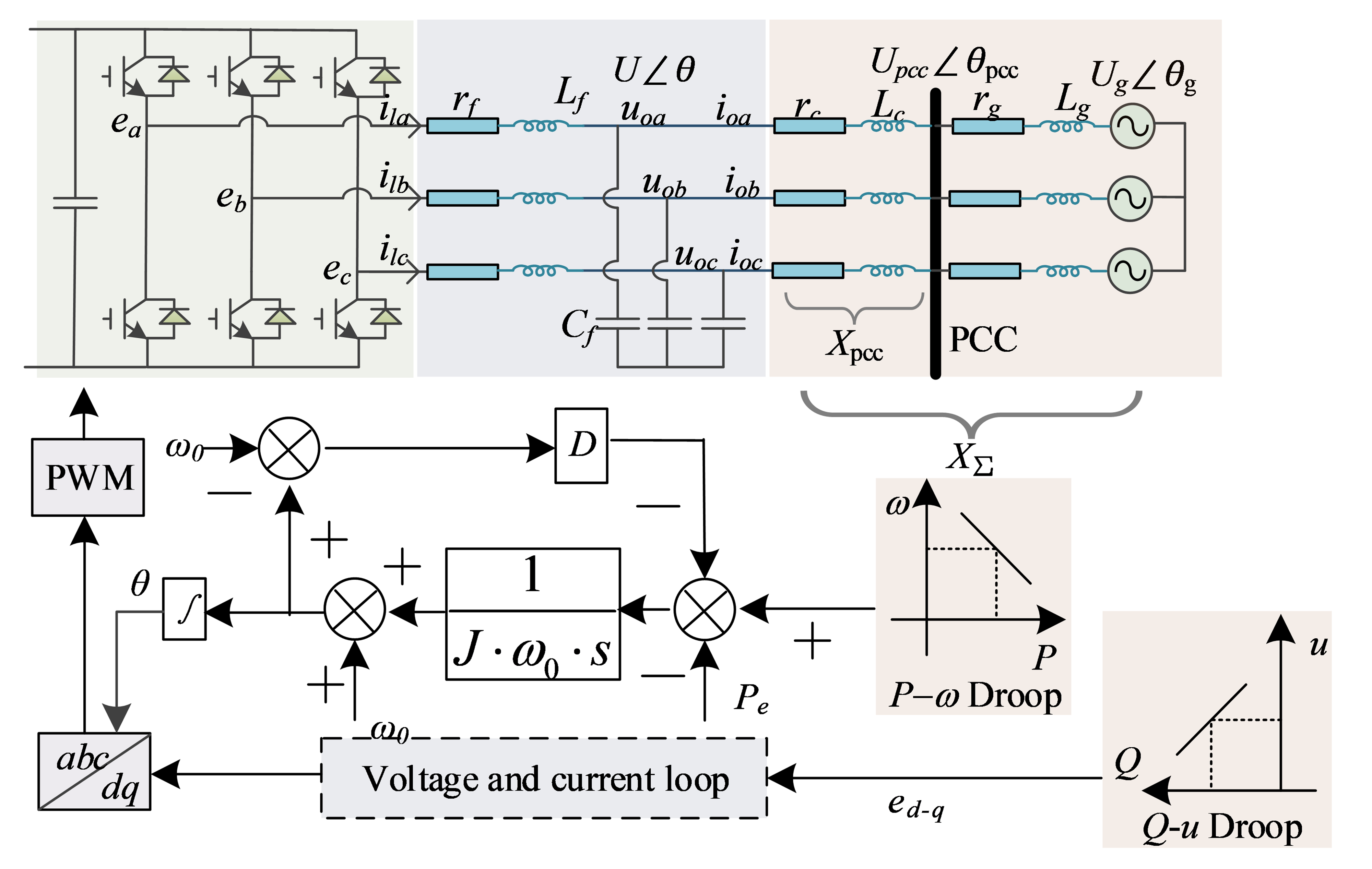
Figure 1 illustrates the grid-connected topology of a VSG converter, where Lf and Cf are the output filter inductor and capacitor of the VSG, respectively; rf is the equivalent resistance of the filter inductor; rc and Lc are the equivalent resistance and inductance of the transmission line, respectively; rg and Lg are the equivalent resistance and inductance of the grid, respectively; eabc and ilabc are the terminal voltage of the VSG and the filter inductor current, respectively; uoabc and ioabc are the output voltage and current of the VSG, respectively; Upcc and Ug are the PCC voltage and grid voltage, respectively; and XPCC and X are the reactance from the VSG to the PCC and the total reactance to the grid, respectively.
The VSG emulates the inertia and damping of a synchronous generator by replicating the rotor motion equation as follows [26,27]:
J d ω d t = P m ω 0 P e ω 0 D ( ω ω 0 )
where J is the virtual inertia, D is the damping coefficient, and ω and ω0 are the virtual angular frequency and its initial value, respectively. The active power output and reference of the VSG are Pe and Pm, respectively.
For reactive power control, the VSG typically uses an integral droop controller to mimic the Q-V droop characteristics of the synchronous generator exciter. The control law is expressed as follows:
Q m = Q r e f + K v ( U n U ) e d = K s ( Q m Q e ) + U n
where ed-q is the Q-V droop control output voltage; K is the integral coefficient; Un is the nominal voltage; U is the output voltage of the VSG; Kv is the voltage droop coefficient; the reactive power reference and command are Qm and Qref, respectively; and the reactive power output of the VSG is Qe.
Both voltage and current loops are regulated by conventional PI controllers. The active and reactive power outputs of the VSG are obtained from instantaneous power calculations filtered by a low-pass filter.

2.2. Conventional PQ-Reference-Based FRT Strategy for VSGs

VSG fault ride-through strategies can be implemented in different forms, including virtual-impedance-based current limiting, voltage-command limiting, mode switching, and power-reference adjustment. In this subsection, the baseline strategy refers specifically to a PQ-reference-based FRT scheme, in which the active and reactive power references are adjusted during faults while the voltage-source control structure of the VSG is retained. This strategy is adopted as the comparison baseline because it requires only minor modifications to the outer power-reference loop and is easy to extend to multi-VSG coordination.
To mitigate the adverse effect of the rated voltage Un on the reactive power control loop during FRT, Un in (2) is replaced by the fault-stage terminal voltage U, and the voltage droop coefficient Kv is set to zero. Under these conditions, the active and reactive power outputs are mainly determined by the fault-stage references Pref and Qref, which are typically expressed as follows:
P r e f = min U I max 2 i q _ r e f 2 P r e f 0   , U p c c _ l o w U p c c 0.85 0 , U p c c U p c c _ l o w
Q r e f = max U k q 0.85 U p c c I max i q _ r e f U 2 I max 2 P r e f 0 2   , U p c c _ l o w U p c c 0.85 U I max , U p c c U p c c _ l o w
where Pref0 is the initial active power reference, Upcc_low is the critical voltage threshold for full reactive power support, kq is the reactive droop coefficient, and Imax is the maximum current that the VSG permits.
From (3), one can derive iq_ref = kq(0.85 − Upcc)Imax. When the reactive current reaches its upper limit, i.e., iq_ref = Imax, the corresponding voltage is Upcc_low. Thus,
U p c c _ l o w = 0.85 1 k q
For example, when Imax = 1.04 and kq = 1.54, we obtain Upcc_low = 0.2 and kqImax = 1.6. Under these conditions, (3) and (4) satisfy the FRT requirements during fault periods.

3. Quantitative Characterization and Evaluation of VSG Grid-Forming Capability During Faults

The short-circuit ratio (SCR) is commonly used to evaluate the grid strength. Specifically, we define an extremely weak grid as SCR < 1.5, a weak grid as 1.5 < SCR < 2.5, and a strong grid as SCR > 2.5. In this article, we use the SCR to characterize the relationship between the VSG terminal and the equivalent AC system, and the SCR is expressed as follows:
S C R = S a c / P N = U N 2 / P N X N Σ 1 / X Σ
where Sac, PN, XN∑, and X are the short-circuit capacity at the VSG terminal, rated VSG power, actual equivalent impedance, and per-unit equivalent impedance between the VSG and AC system, respectively.

3.1. Operating Region of the VSG During Faults

To facilitate the theoretical analysis, the AC line is assumed to exhibit predominantly inductive characteristics, i.e., R/X ≪ 1, and the line resistance is neglected. This assumption is mainly adopted to highlight the dominant influence of line reactance on the power transfer capability and power-angle stability characteristics of the VSG system, and it is widely used in transmission-level weak-grid scenarios and inductance-dominated grid-connected systems.
It should be noted that the line resistance mainly affects active power losses and additional damping characteristics, while its influence on the reactance-dominated voltage–power-angle relationship is relatively limited. According to the parameters listed in Table 1, the equivalent grid resistance and reactance are Rg = 0.02 pu and Xg = 0.7 pu, respectively. Therefore, the ratio Rg/Xg is approximately 0.03, indicating that the investigated weak-grid system exhibits predominantly inductive characteristics. Under this condition, neglecting the resistance introduces only a limited error in capturing the dominant voltage–power-angle relationship and feasible LVRT operating-region boundary.
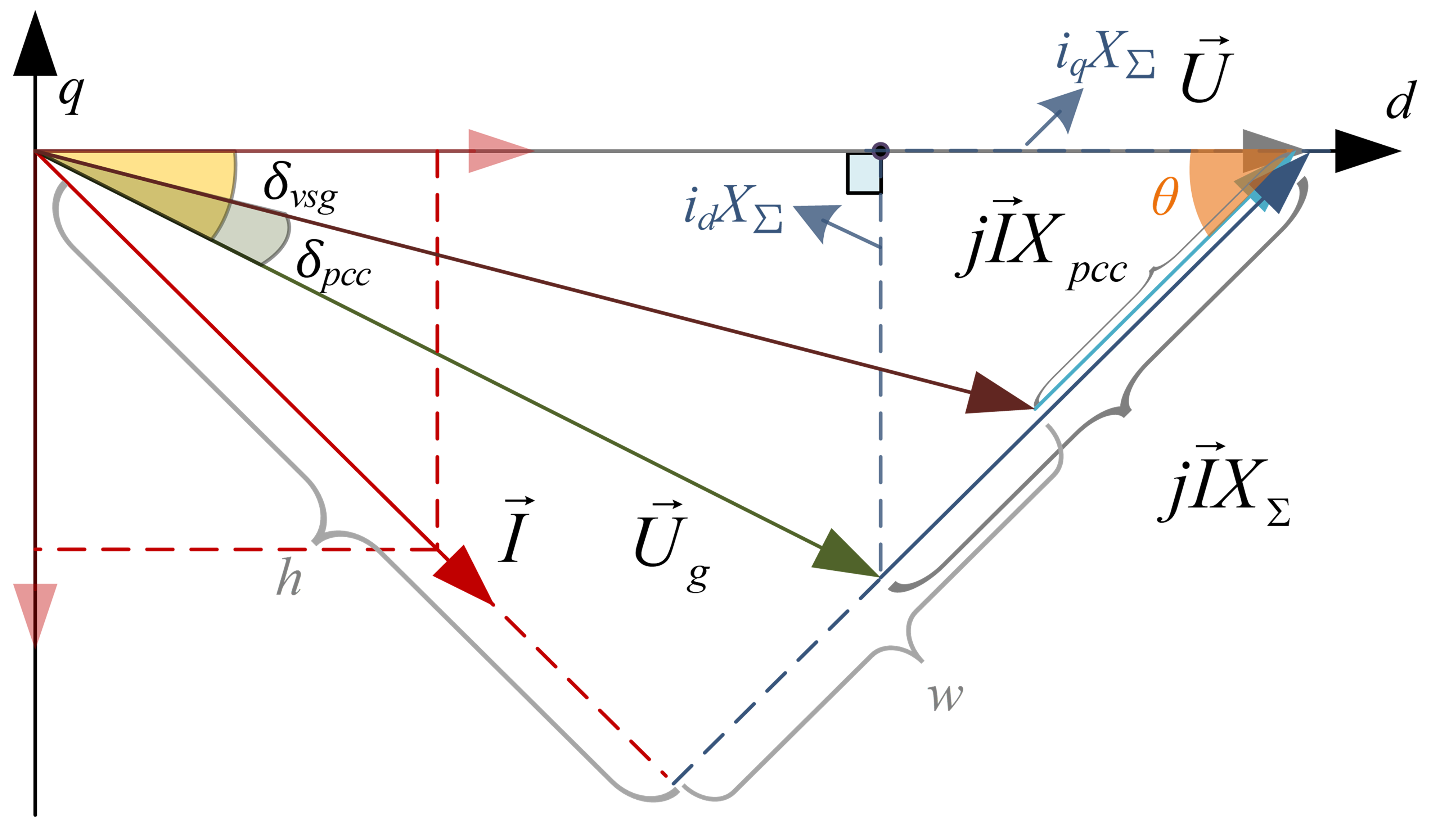
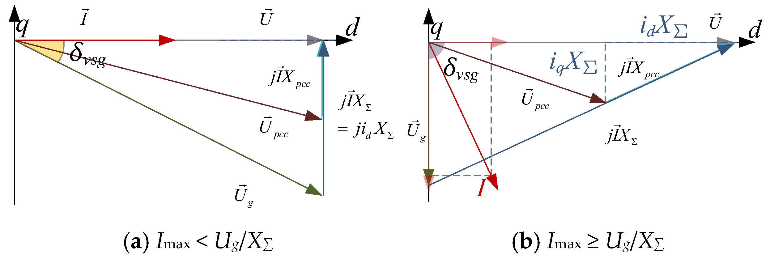
Under this assumption, the VSG voltage vector diagram is established in the dq reference frame. In the quasi-steady state, the terminal voltage vector is aligned with the d-axis, as shown in Figure 2.
During operation, the VSG satisfies:
U = U g + j X Σ I
Under the terminal-voltage-oriented dq frame, the q-axis component of the terminal voltage is zero, i.e., (Uq = 0). Considering the current saturation boundary (I = Imax), the terminal voltage magnitude can be expressed as
U d = U g 2 X Σ 2 i d 2 + X Σ I max 2 i d 2
P n e t = U d i d = U g 2 X Σ 2 i d 2 + X Σ I max 2 i d 2 i d
Q n e t = U d i q = U g 2 X Σ 2 i d 2 + X Σ I max 2 i d 2 I max 2 i d 2
where Pnet is the active power output of the VSG in the current grid conditions, which can be used to characterize the inherent network characteristic curve in different fault scenarios. Based on (9), when the d-axis current id varies within [0, idmax], the power characteristic curves of the VSG can be obtained to determine its operating region during faults.
From the VSG power calculation equations, considering the constraint of the power angle (δvsg < 90°), current id satisfies:
P e = U g U X Σ sin δ v s g = U i d
i d U g / X Σ
Because idmax is the maximum allowable d-axis current of the VSG, the following must also hold:
i d max = min U g / X Σ , I max
Equation (13) indicates that the d-axis current is constrained by both the converter current limit and the power-angle stability boundary. When Imax < Ug/X, the boundary is determined by current saturation with id = Imax and iq = 0. Otherwise, it is determined by the power-angle stability limit id = Ug/X.
As illustrated in Figure 2, by defining a triangle with sides g1 = Ug, g2 = IX, and g3 = U and applying Heron’s formula, we can express the PCC voltage as follows:
A = L L g 1 L g 2 L g 3
w = h / t a n ( θ ) X p c c I
U p c c = h 2 + w 2
where
L = g 1 + g 2 + g 3 2 h = 2 A / g 2 θ = cos 1 U 2 + I X Σ 2 U g 2 2 U I X Σ
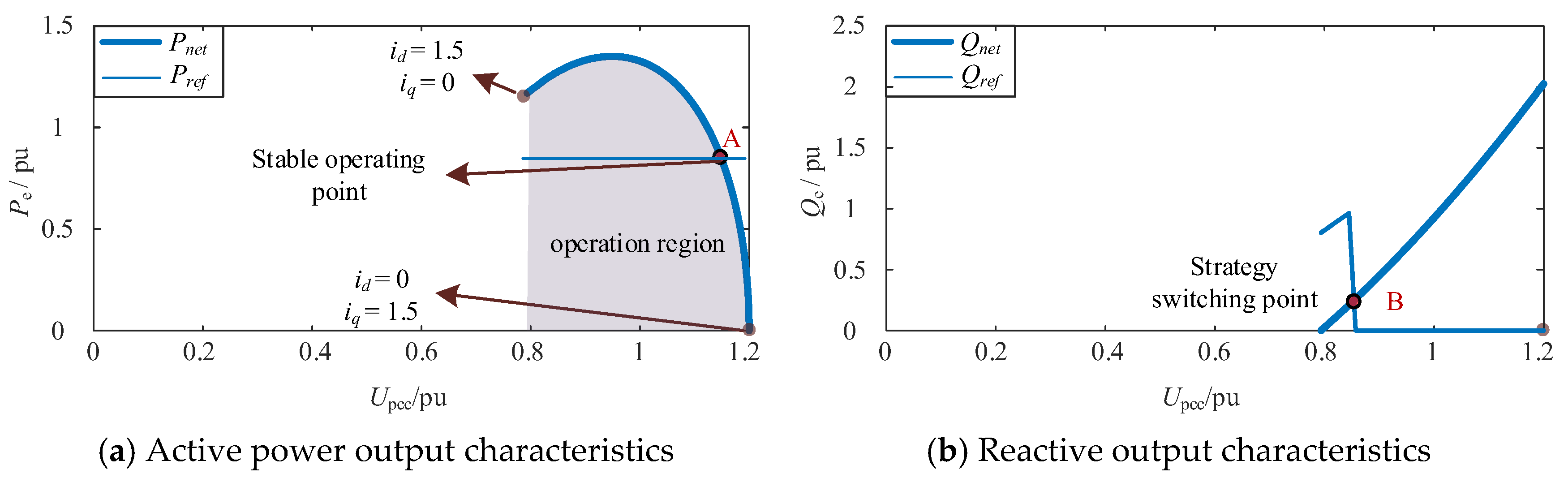
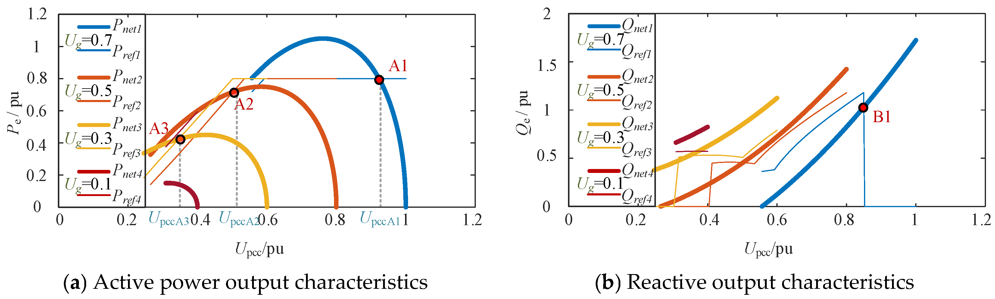
Combining (3), (4), (9), (10) and (16), the operating region of the VSG for id ∈ [0, idmax] under different grid voltages can be derived, as shown in Figure 3 and Figure 4.
Figure 3 illustrates the active and reactive power characteristics under normal conditions with Imax = 1.5 pu. Figure 3a shows the active power region; Figure 3b shows the reactive power characteristics. In Figure 3a, when the reference power corresponds to point A, the system converges to a stable equilibrium through the self-regulation mechanism of the VSG. When id = 0, the current capacity of the inverter is fully allocated to the q-axis current iq, which enhances the reactive support and increases the PCC voltage. Once the PCC voltage falls below 0.85 pu, the LVRT control strategy is triggered at point B, as shown in Figure 3b. With increasing id, the active power output increases, but the voltage boosting effect at PCC diminishes.
The maximum power output current is:
I d max = E I max E 2 + I max 2 X Σ 2
Figure 4 reveals the effect of fault-induced voltage sags on the VSG operation. In Figure 4a, deeper voltage sags decrease the active–reactive power capacity and operating region, which reflects the shrinking stability boundary under severe faults. By setting the active reference Pref = 0.8, the LVRT strategy enables the system to converge to stable equilibrium points A1, A2, and A3 for voltage sags of 0.8–0.4 pu. These points represent feasible active operating references under fault conditions. Thus, during LVRT, Pref must remain below the maximum value of the network characteristic curve; otherwise, stability cannot be maintained.
When the voltage sag becomes too severe (e.g., Ug = 0.1), the system fails to sustain an active power output (Pref = 0) and relies on only reactive power to support the PCC voltage. However, as Figure 4b shows, under deep sags, the reactive reference curve and actual characteristic curve may not intersect, which reduces the LVRT capability.
Point A1 corresponds to a PCC voltage exceeding the 0.85 pu threshold, whereas point B1 is exactly at the threshold. Under these conditions, the traditional LVRT strategy may make the VSG oscillate between fault-ride-through and normal operation modes, which weakens the voltage support and causes unstable control.
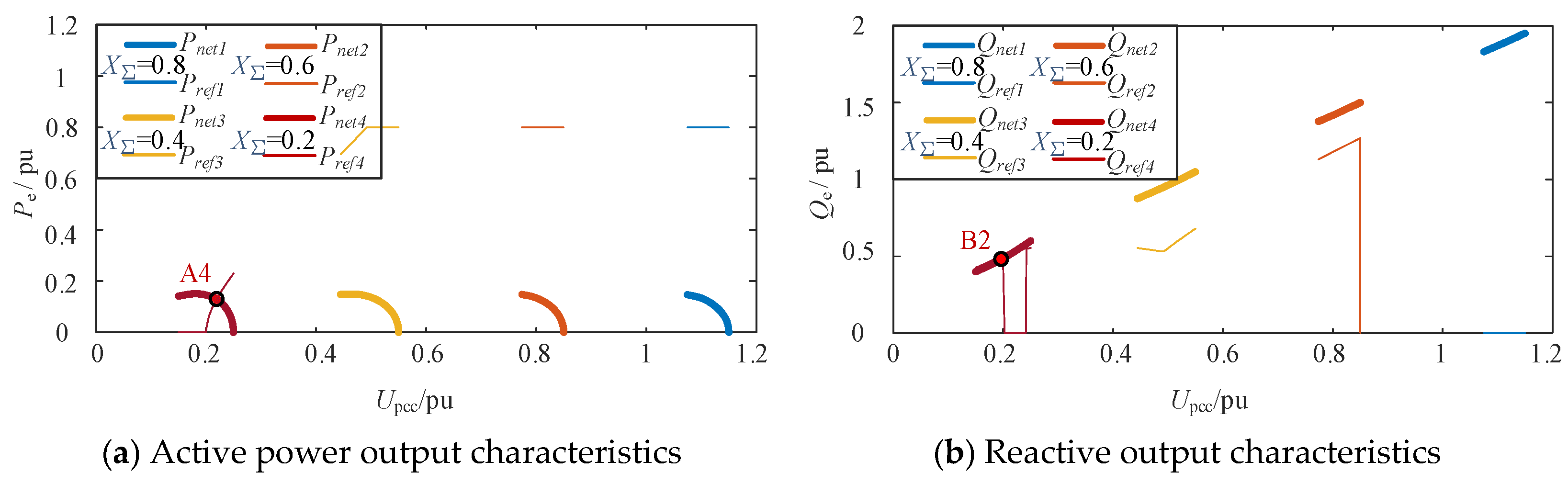
To analyze the effects of different grid strengths on the FRT performance, Figure 5 shows the operating regions of the VSG for different equivalent impedances.
In Figure 5, the difficulty of FRT significantly increases in weak and extremely weak grids. Because the power characteristic curves and grid characteristic curves fail to intersect, stable equilibrium points cannot be formed, which results in unsuccessful ride-through. Conversely, in strong grids, as Figure 5a shows, point A4 demonstrates that stable FRT remains achievable. Similarly, in Figure 5b, point B2 indicates that reactive support persists even when the active power drops to zero. However, with increasing active power, the reactive output decreases, which decreases the voltage support capability and potentially induces secondary oscillations. Consequently, during faults, the VSG must provide sufficient voltage support and promptly restore the power angle stability. The existing LVRT methods often struggle to coordinate these dual objectives, which may cause secondary transients or oscillations and constrain their effectiveness in weak and extremely weak grid scenarios.

3.2. Feasible Fault Ride-Through Region and Fault Classification of the VSG

The intersection between Pref and Pnet is used here only as a quasi-steady-state equilibrium existence criterion. It does not imply that Pref = Pnet is maintained during the entire fault transient, because frequency deviation and rotor-angle dynamics may cause temporary power imbalance. Therefore, Pref < Pnet is adopted to judge whether a feasible equilibrium point can be formed under the current voltage and current constraints.
In Figure 4b, when id = idmax and Pref < Pnet, the two curves intersect, which constitutes a feasibility condition for FRT. In the fault region, the following holds:
U p c c _ l o w < U g + X Σ X p c c I max < 0.85
According to (13), idmax has two possible cases, as illustrated in Figure 6. When Imax < Ug/X, idmax = Imax, as shown in Figure 6a. In this case, iq = 0, whereas iq_ref = kq(0.85 − Upcc)Imax is not necessarily zero.
Based on (4) and (9), and considering the vector states in Figure 6, we obtain:
P r e f P n e t = U I max 2 k q 0.85 U p c c I max 2 I max
Equation (19) is always less than zero, which ensures that Pref < Pnet. Thus, the system has a stable equilibrium point and satisfies the feasibility condition.
When ImaxUg/X, idmax = Ug/X and δvsg = 90°, as shown in Figure 6b. From (8), we have U = iqX. Combining (4) and (9) with the vector states in Figure 6b yields:
U p c c = U g 2 X p c c 2 X Σ 2 + I max X Σ 2 U g 2 X Σ X p c c 2 X Σ 2
Based on the above analysis of Imax, the feasible region of FRT can be constructed.
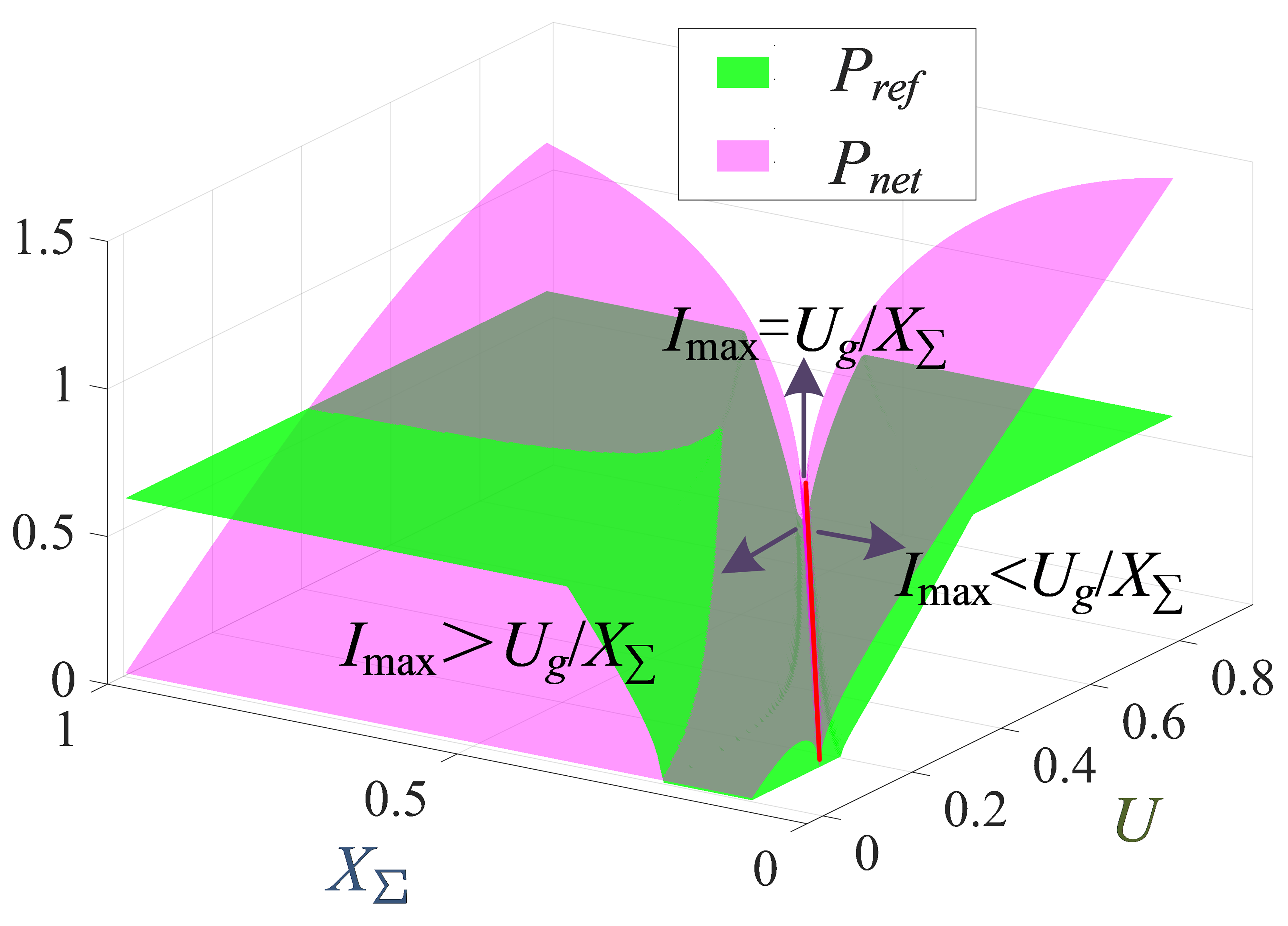
The fault-region classification is obtained by comparing the active power reference Pref with the network power transfer capability Pnet under the current limit, power-angle stability boundary, and LVRT voltage thresholds. As shown in Figure 7, when Imax < Ug/X, the d-axis current is limited by the converter current capability, and the condition Pref < Pnet can generally be satisfied. When Imax > Ug/X, the d-axis current is limited by the power-angle stability boundary, and only part of the region remains feasible for FRT.
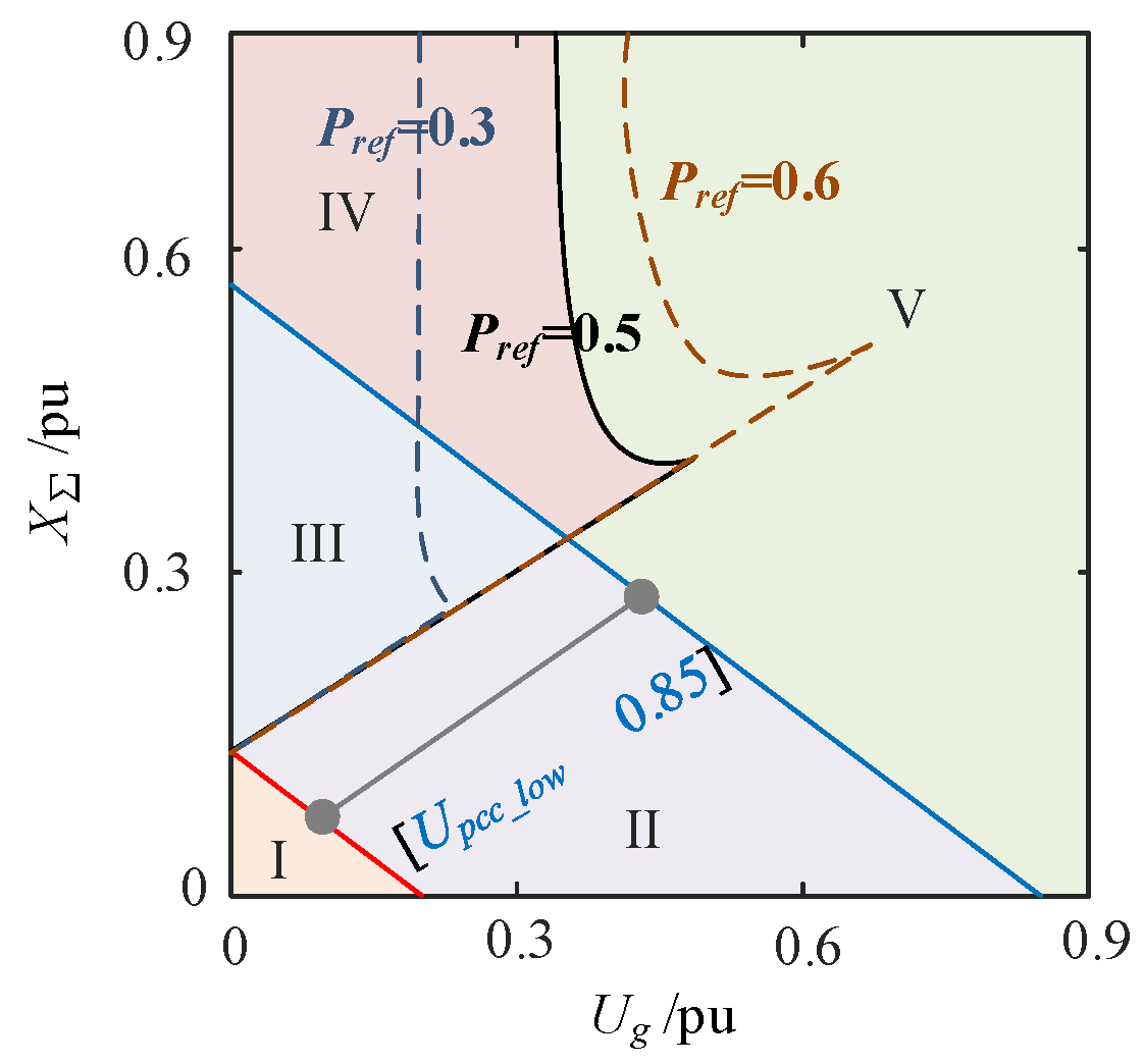
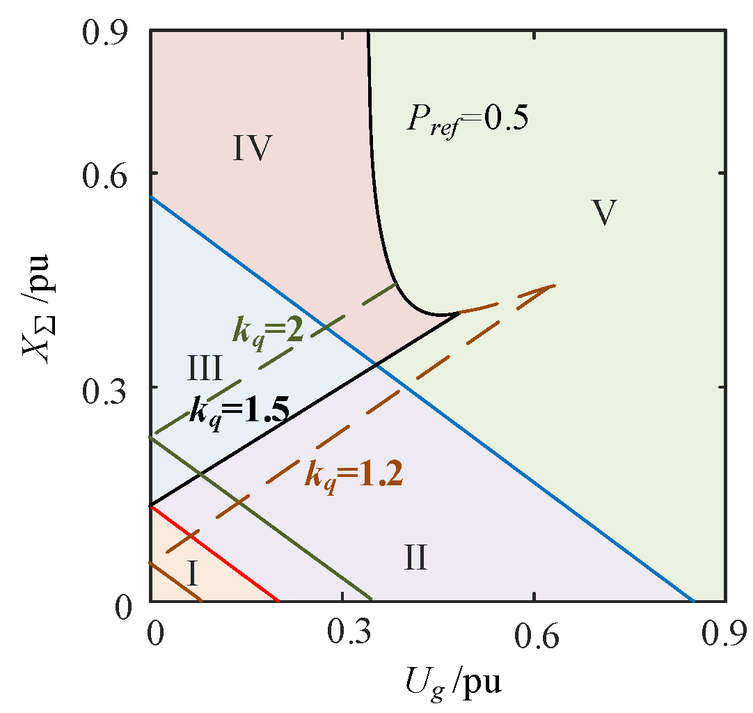
Based on these constraints, Figure 8 divides the operating space into five regions. Region I denotes extremely severe faults, where the voltage sag is too deep to sustain active power transfer. Region II corresponds to mild faults, where a stable equilibrium can be formed with effective PCC voltage support. Regions III and IV are infeasible severe-fault regions, where Pref > Pnet and no stable equilibrium exists, leading to possible power-angle divergence. Region V is the controllable fault region, where Pref < Pnet and the VSG can maintain a stable operating point. However, excessive reactive current injection may raise Upcc above 0.85 pu, resulting in repeated switching between LVRT and normal operation.
Thus, the regions in Figure 8 should be interpreted as feasibility regions under the selected Pref, Imax, X, and LVRT voltage thresholds, rather than as fixed classifications determined only by the grid voltage magnitude.

4. LVRT and Coordinated Multi-VSG Strategy

4.1. Improved Active Power LVRT Strategy

When a voltage sag occurs, a smaller amplitude difference between grid voltage and VSG output voltage is more favorable to reduce the fault current level. This characteristic effectively shrinks Regions III and IV and enhances the LVRT capability. Setting the VSG active power output to zero during grid faults is theoretically the safest approach because it maximizes the reactive voltage support. However, in practice, an active power must still be supplied to maintain the grid stability.
Therefore, based on traditional LVRT strategies, we modified the constant active power reference into an adaptive value that varies with the grid voltage and is constrained by the original strategy. This design mitigates sudden current surges caused by the mismatch between demanded and delivered power while ensuring the overall system stability. The current-limiting and voltage-dependent active power reduction is expressed as follows:
P I U = U I max 2 i q _ r e f 2
and the voltage-dependent active power reduction is given by
P V U = P r e f 0 U U n 2
To further ensure synchronization stability under severe voltage sags, a power-angle stability margin constraint is introduced. The maximum transferable active power is given by
P max = min U g U X Σ , U I max 2 i q _ r e f 2 2
and the active power reference is constrained within a safety margin as
P r e f γ P max , 0 < γ < 1
where γ is a stability margin coefficient that prevents the operating point from approaching the synchronization limit.
Accordingly, the optimal steady-state active power reference is defined as
P r e f = min P I U , P V U , P r e f 0 , γ P max , U p c c _ l o w U p c c 0.85 0 , U p c c U p c c _ l o w
Furthermore, to avoid abrupt power variation and suppress post-fault oscillations, a voltage-dependent ramp-rate constraint is imposed:
d | P r e f | d t R p U P C C = R p 0 U P C C / U n m
where RP0 is the nominal ramp limit and m determines the voltage sensitivity.
The final active power reference is updated in a discrete form as
P r e f k = P r e f k 1 + s a t [ R p Δ t , R p Δ t ] P r e f P r e f k 1

4.2. Improved Reactive Power LVRT Strategy

With the adopted reactive power sign convention, positive Qe denotes reactive power injection from the VSG to the grid. Based on the fundamental power flow equation of power systems, for a purely reactive line, we have:
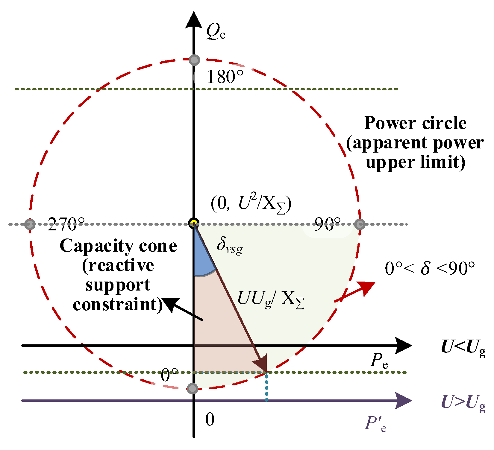
P e 2 + Q e U 2 X p c c 2 = U U p c c X p c c 2
Equation (28) is the power circle equation with its center at (Pe, Qe) = (0, U2/Xpcc) and radius UpccU/Xpcc. Accordingly, when the active power is Pe, the feasible range of Qe is:
U U p c c X p c c P e 2 + U 2 X p c c Q e U U p c c X p c c P e 2 + U 2 X p c c
The overall power circle and capability cone are illustrated in Figure 9.
To ensure that the system provides maximum reactive support while delivering active power, three limiting factors are considered: current, equivalent reactance, and apparent power, as expressed in (30)–(32). These factors collectively define the reactive power capability cone for optimal implementation of LVRT.
Q I P e , U = U 2 I max 2 P e 2
Q X P e , U = k q U U n X p c c P e 2 + U 2 X p c c
Q S P e , U = U U n S 2 P e 2
Then, the comprehensive available reactive capacity is defined as the minimum of the three, and negative values are clipped:
Q c a p P e , U = max 0 , min { Q I , Q X , Q S }
The reactive current reference is generated by projecting the voltage-error-driven signal into the cone formed by (Imax, Xpcc, S). Under deep voltage sags or current saturation, the remaining capacity is fully allocated to the reactive support. Thus, the proposed reactive power LVRT strategy is:
Q r e f = sat Q c a p , Q c a p U k q 0.85 U p c c I max , U p c c _ l o w U p c c 0.85 U I max , U p c c U p c c _ l o w
where S is the VSG apparent power, and sat[a,b](x) = min{b,max{a,x}} is the interval projection function.
This formulation enables the VSG to provide reactive support for a given active-power output under fault conditions while suppressing excessive current stress and improving the grid-friendliness of distributed generators.
To balance the voltage support, the reactive output is refined as follows:
e d = K s ( Q m Q e ) + α U + β U p c c
where α and β are voltage support coefficients that satisfy α + β = 1.

4.3. Adaptive Reactive Power Droop Control Strategy

As indicated by (21) and (34), significant influence is exerted by the reactive power droop coefficient kq on the allocation of active and reactive power references, and the distribution of the feasible FRT region is directly determined by kq, as illustrated in Figure 10. When kq is reduced, the uncontrollable Regions III and IV are enlarged, whereas the extremely severe fault Region I is reduced. Conversely, when kq is increased, the reactive power support capability is enhanced; however, the operating point may be driven into the uncontrollable region. Therefore, a smaller kq should be adopted under severe voltage sag conditions to ensure that the system remains within the controllable region, whereas a larger kq should be employed under mild voltage sag conditions to improve voltage support capability and stability. Based on these observations, an adaptive kq regulation strategy dependent on the voltage sag severity is introduced in this paper.
The proposed adaptive kq control strategy is formulated as follows:
k q = a x b + c x + d
where x = 0.85 − Upcc denotes the voltage deviation within the LVRT region, and a, b, c, and d are tuning parameters.
The polynomial form in (36) is adopted to achieve smooth adaptive regulation between the voltage sag severity and the reactive power support capability; a nonlinear parametric function is adopted to describe the mapping relationship between kq and the PCC voltage deviation. Compared with fixed-parameter or linear regulation schemes, the proposed function provides greater flexibility in adjusting kq, enabling a continuous and smooth variation under different fault severities while satisfying the monotonicity requirement, current limitation constraint, and feasible LVRT operating-region constraint. Furthermore, the proposed function only involves simple algebraic operations, avoiding the additional computational burden introduced by online optimization and facilitating practical controller implementation.
To ensure a reasonable regulation trend of kq with respect to the voltage sag severity, a monotonicity constraint should be satisfied, i.e.,
d k q d x = a b x b 1 + c < 0
Furthermore, to prevent excessive reactive power injection from driving the converter into an overcurrent condition, the following current constraint should be satisfied:
i q = k q x I max I max
In addition, according to relevant grid-connection standards such as IEEE 2800, the range of kq is further constrained as 0.5 < kq < 3.
On the other hand, to ensure the existence of feasible operating points during fault conditions, the active-power feasible-region constraint should also be satisfied PrefPe ≠ ∅.
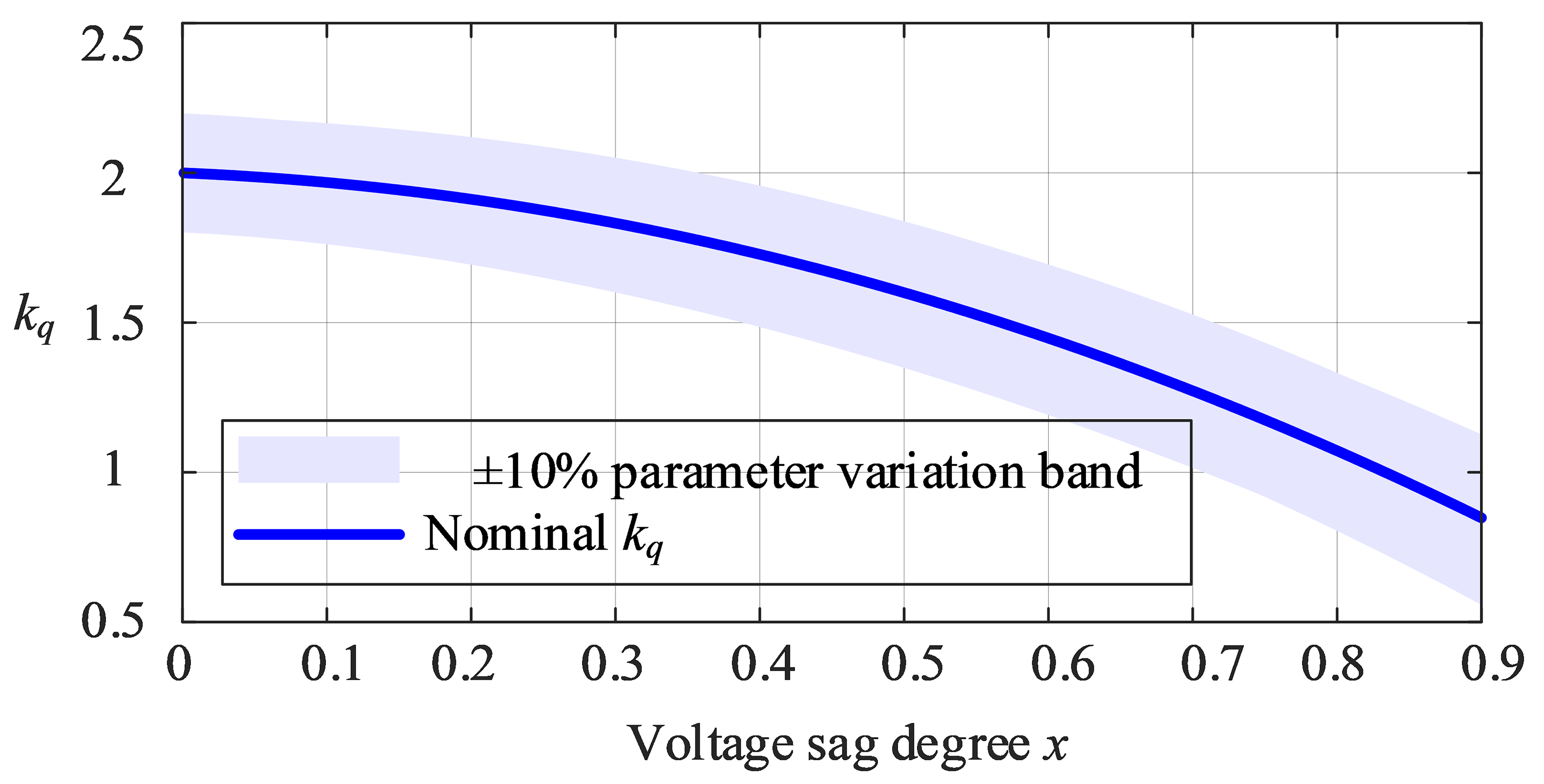
Figure 11 illustrates the proposed adaptive droop curve and its ±10% parameter perturbation band. It can be observed that a consistent monotonic variation trend is maintained within the parameter perturbation range, indicating strong robustness of the proposed adaptive droop function against parameter uncertainty.
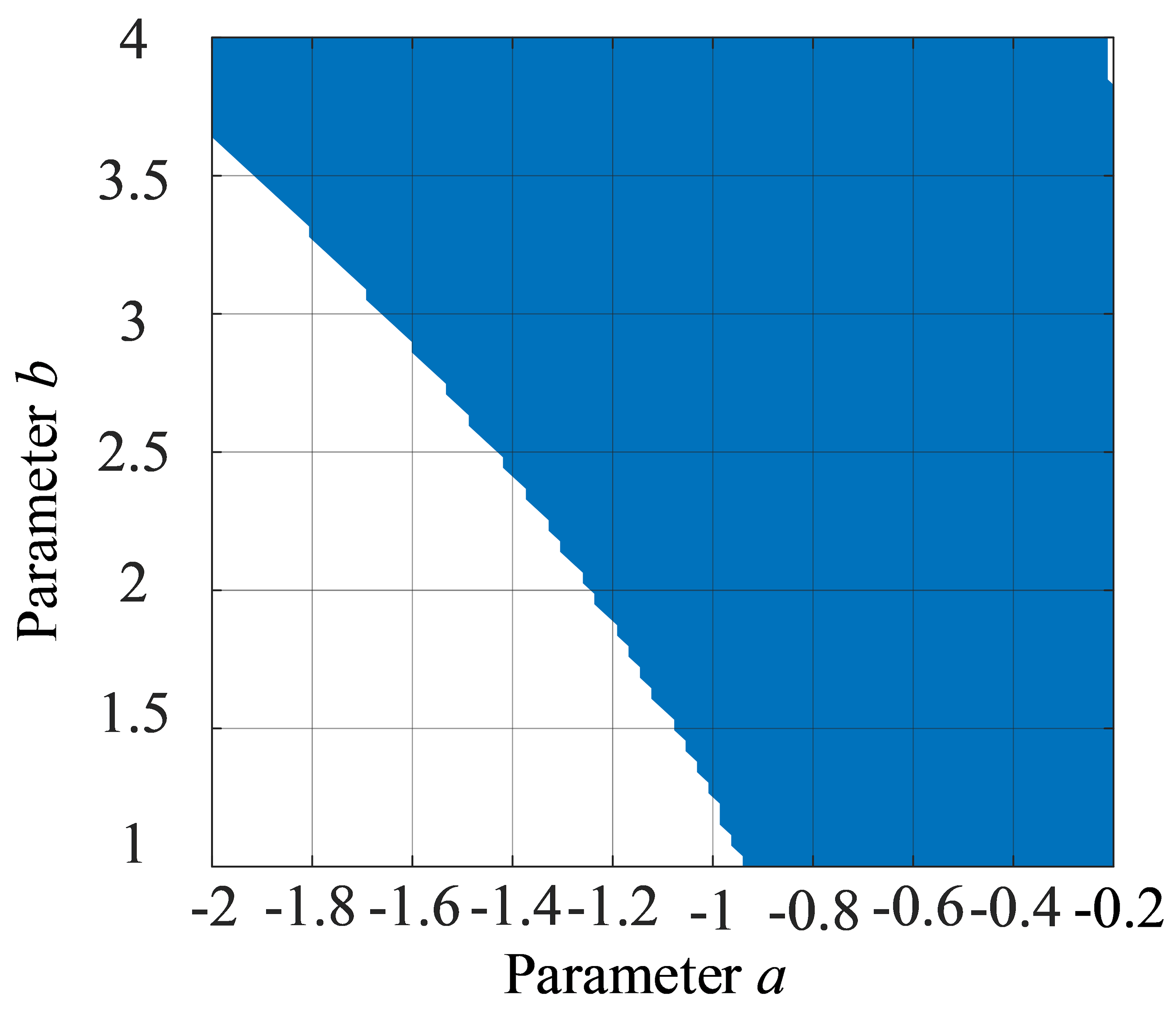
Figure 12 further illustrates the feasible parameter region of the adaptive droop coefficients under monotonicity, current-limiting, and LVRT stability constraints. It can be observed that parameter combinations located within the feasible region can simultaneously satisfy the droop-characteristic constraint, current safety constraint, and stable fault ride-through operation requirement, thereby providing a theoretical basis for parameter tuning. In contrast, when the parameters exceed the feasible region, overcurrent conditions, feasible-region disappearance, or uncontrollable system operation may occur.
In summary, a multi-constraint-based parameter tuning method is established in this paper. First, the monotonic variation trend of kq with respect to the voltage deviation is determined according to the reactive power support requirements under different voltage sag severities. Second, the maximum allowable range of kq is restricted by the reactive current limitation to avoid insufficient current margin caused by excessive reactive power injection. Furthermore, feasible parameter combinations that satisfy the stable operating requirements are selected according to the LVRT feasible operating-region constraints. As shown in Figure 12, the parameter region satisfying the monotonicity, current-limiting, and stability constraints constitutes the feasible tuning region of kq. Therefore, the nominal parameters are selected from this feasible region, and the robustness of the selected parameters against uncertainties is verified through the ±10% parameter perturbation analysis.

4.4. Performance Analysis of the Improved LVRT Strategy

Based on the proposed strategy, Figure 13 shows the operating regions of the VSG for different grid voltages.
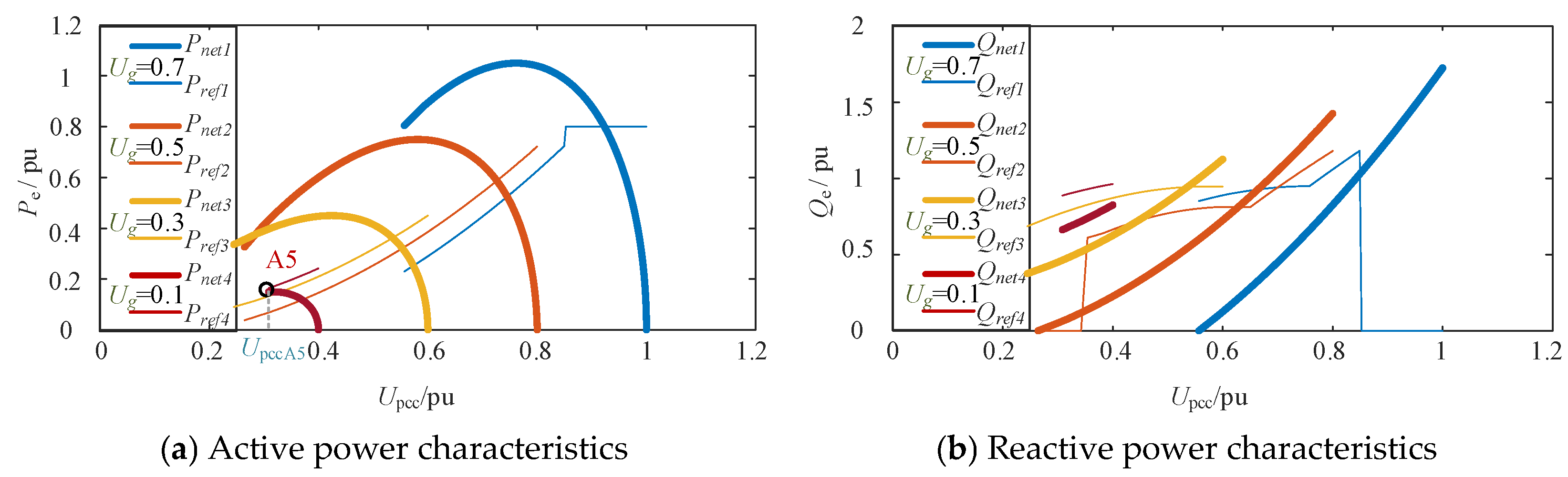
A comparison of Figure 13a with Figure 4a shows that the proposed method enables LVRT at lower active power reference values, which significantly enlarges the feasible operating region. For example, under traditional strategies, when Ug = 0.1, the VSG cannot reach a synchronous stable point: the lowest stable point is A3 in Figure 4a with Upcc ≈ 0.38. In contrast, with the proposed method, a new stable boundary point A5 emerges (Figure 13a) with Upcc ≈ 0.32. Thus, the proposed method decreases the voltage support threshold, which enables the VSG to maintain FRT capability under deeper voltage sags.
In Figure 13b, the proposed strategy yields a larger reactive power output during LVRT than the traditional approach. The reactive power increases by approximately 15–20%, which enhances the PCC voltage support. These results indicate that the proposed method improves the feasibility of active power ride-through, strengthens the voltage stability, and improves the LVRT performance of the VSG under weak and extremely weak grid conditions.

4.5. Coordinated Multi-VSG Consensus-Based Ride-Through Strategy

In renewable energy plants, multiple VSG units are typically operated in parallel. During LVRT conditions, reference mismatch, unequal power sharing, and inter-unit oscillations may be caused by independent power-reference adjustment among parallel VSGs. In addition, different rated capacities, line impedances, and remaining current margins are generally exhibited by practical VSG units. Under such conditions, some units may be driven prematurely to current-limiting boundaries by conventional average-consensus strategies, while the support capability of other units remains underutilized, thereby reducing the overall fault ride-through capability and voltage support performance of the system.
To address this issue, a capability-aware weighted consensus mechanism is introduced in this paper, such that coordinated allocation of active and reactive power references during fault conditions can be achieved according to the remaining support capability of each VSG, rather than identical instantaneous power outputs being simply enforced among all units.
Assuming that the system consists of n VSG nodes, the active power reference vector is defined as follows:
P r e f = P r e f 1 , P r e f 2 , P r e f 3 , , P r e f n T
To characterize the available support capability of each VSG, the following weighting factor is introduced:
w i = ξ i j = 1 n ξ i
where ξi denotes the support capability index of the i-th VSG. By jointly considering the rated capacity and the remaining current margin, ξi can be defined as
ξ i = S i r a t e d M i
where Sirated represents the rated apparent power of the i-th VSG, and Mi denotes its remaining current margin, which is expressed as
M i = I max i 2 i q i 2
Accordingly, higher coordination weights are assigned to VSG units with larger remaining current margins and higher rated capacities, thereby enabling a more effective utilization of the overall converter support capability during fault conditions.
Based on the above weighting definition, the weighted consensus iteration process can be expressed as follows:
P ˙ r e f = L W 1 P r e f
where
W = d i a g w 1 , w 2 , , w n
where W denotes the weighting matrix, and L = DA represents the Laplacian matrix of the communication network. Here, A = [zij] denotes the adjacency matrix, and D = diag(di) denotes the degree matrix.
By discretizing (43), the following expression can be obtained:
P r e f k + 1 = I η L W 1 P r e f ( k )
where η > 0 denotes the step-size factor used to determine the convergence rate of the consensus process. The convergence condition is given by
0 < η < 2 λ max L W 1
where λmax() denotes the maximum eigenvalue of the matrix.
Under the proposed weighted consensus mechanism, the active power references of all VSGs asymptotically converge to a capability-aware weighted allocation result, i.e.,
lim P r e f i k = w i j = 1 n P r e f j 0 , i 1 , , n
Accordingly, VSG units with stronger remaining support capability are assigned larger active power support responsibilities during fault conditions.
The same weighted consensus mechanism can also be applied to the coordinated allocation of the reactive power reference vector Qref. Since different VSG units possess different remaining reactive support capabilities during LVRT conditions, the proposed weighting mechanism enables units with larger current margins and higher capacities to undertake greater reactive power support tasks. Consequently, premature current saturation of individual units can be avoided, while the overall voltage support capability and transient stability of the multi-VSG system can be improved.

5. Case Study Analysis

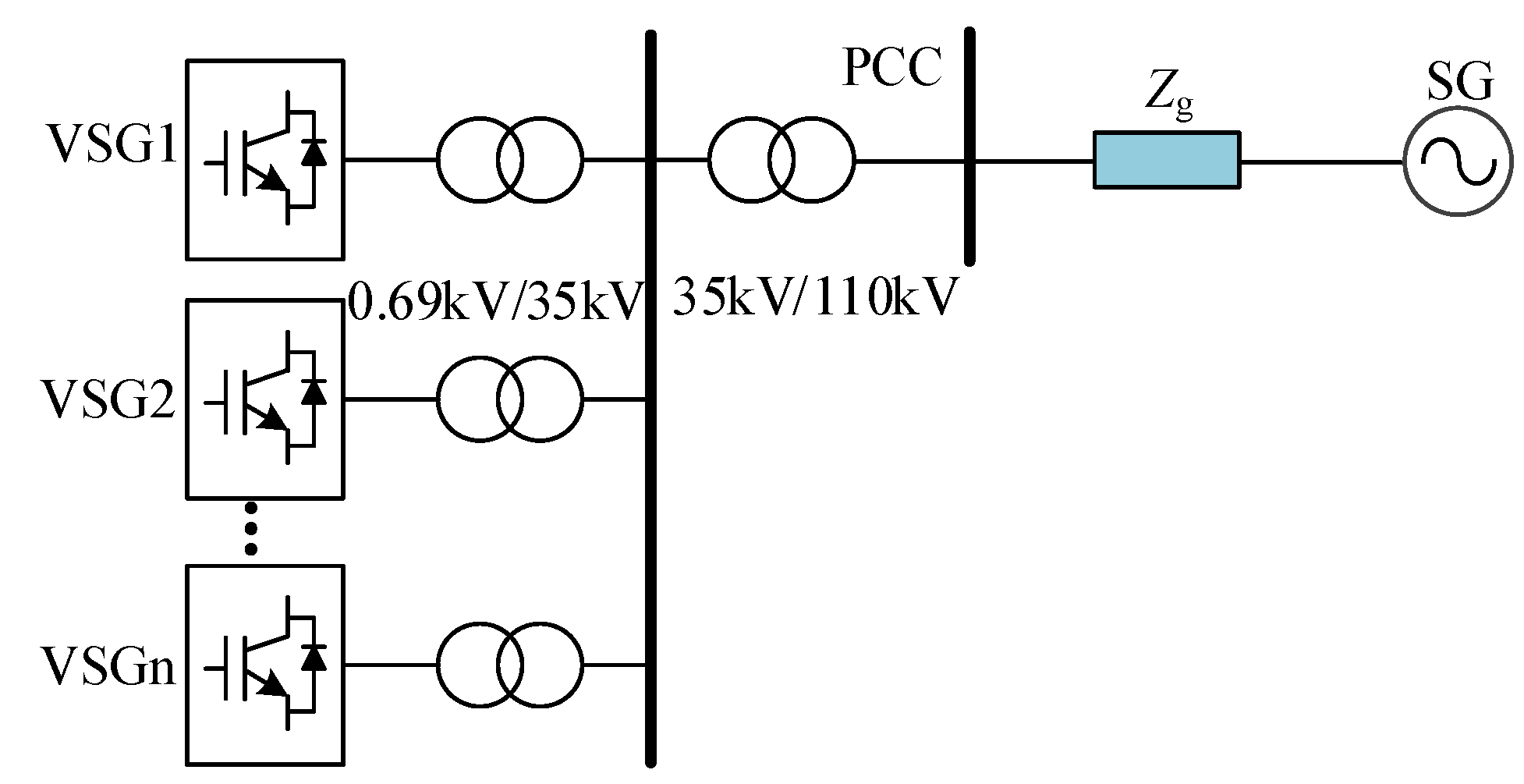
To validate the effectiveness of the proposed method, a multi-VSG parallel grid-connected model was established in MATLAB/Simulink R2024b (MathWorks, Natick, MA, USA), where a synchronous generator represents the grid, as shown in Figure 14. Table 1 lists the initial system parameters.
The parameters in Table 1 were selected to represent a typical MW-level VSG-based grid-connected converter with an LC filter, step-up transformer, and weak-grid connection. The filter and transformer parameters were expressed in per-unit values, and the controller parameters were selected to ensure stable pre-fault operation and to provide a consistent basis for evaluating LVRT performance under current limitation and weak-grid conditions.
According to the SCR definition in (6), the equivalent grid reactance directly affects the grid strength. Therefore, different values of Xg were adopted in the simulations to emulate different grid-strength conditions. Specifically, Xg = 0.3, 0.5, and 0.7 pu were used to represent strong-grid, weak-grid, and extremely weak-grid conditions, respectively. In addition, different voltage sag depths were selected to evaluate the adaptability of the proposed strategy under mild, moderate, and severe fault conditions.
The control parameters of the proposed adaptive LVRT and multi-VSG coordination strategies are listed in Table 2. These parameters are selected according to the feasible-region constraint, current limitation requirement, and consensus convergence condition.

5.1. Single-VSG Performance Under Different Grid Strengths

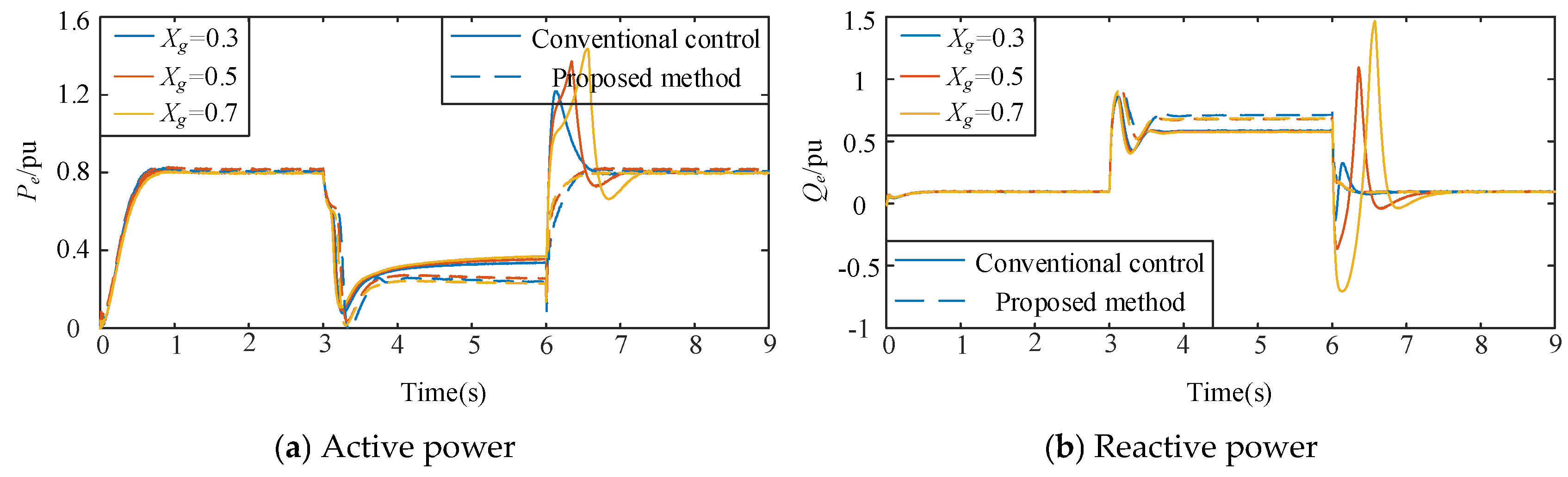
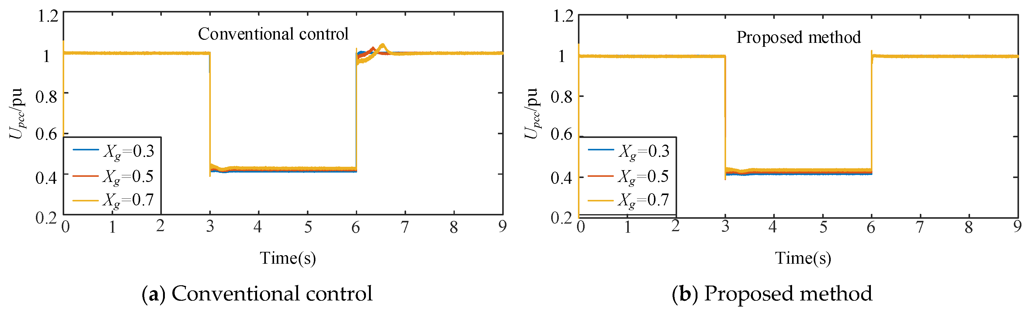
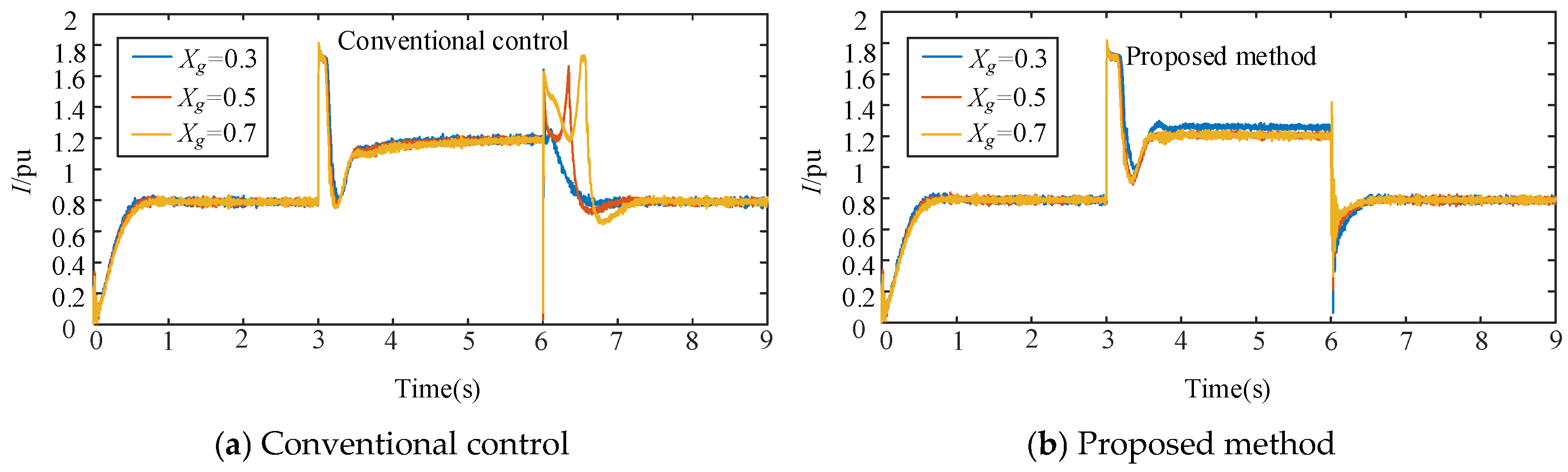
To verify the proposed control strategy, we conducted simulations in a single-VSG grid-connected system. The system operated under normal conditions in the initial stage. At t = 3 s, the grid voltage decreased to 0.4 pu; at t = 6 s, the fault was cleared, and the voltage was restored to its nominal value. Different grid reactance values were selected to represent various SCR conditions: Xg = 0.7 for an extremely weak grid; Xg = 0.5 for a weak grid; and Xg = 0.3 for a strong grid. Figure 15, Figure 16, Figure 17 and Figure 18 show the simulation results.
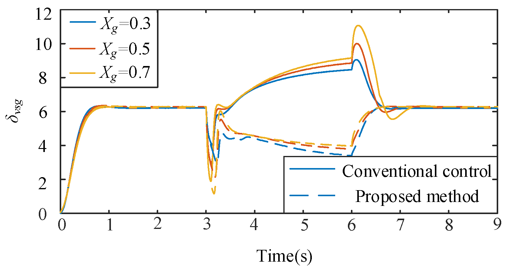
Figure 15 compares the active and reactive power responses of the traditional strategy and proposed strategy during LVRT for different grid strengths. Figure 16 presents the corresponding power angle dynamics. As shown in Figure 15 and Figure 16, with decreasing grid strength, the power fluctuations of the traditional strategy significantly increased during fault transitions, and the cumulative power angle deviation became more pronounced, which made post-fault recovery increasingly difficult. This observation is consistent with the earlier theoretical analysis. The fundamental reason is that the fixed reactive droop coefficient kq in the traditional approach cannot adaptively adjust the reactive support according to the fault depth, which fails to satisfy the stability requirements in weak and extremely weak grids.
In contrast, the proposed method significantly improved the power dynamic performance during FRT. Both active and reactive power exhibited smoother transient responses, post-fault recovery was faster, and the power angle deviations were effectively suppressed.
For the extremely weak-grid condition Xg = 0.7 pu, the conventional PQ-LVRT strategy exhibits a significant active-power overshoot after fault clearance, with an overshoot of approximately 55% and a maximum power-angle deviation of about 10 rad. The system requires approximately 1.5 s to recover to a stable operating range. In contrast, the proposed strategy reduces the active-power overshoot to approximately 20%, decreases the maximum power-angle deviation to about 6 rad, and shortens the recovery time to approximately 0.8 s.
To further verify the voltage support capability and current-constraining performance of the proposed strategy under different grid strengths, the dynamic responses of the RMS voltage at the PCC and the VSG output current magnitude are presented in Figure 17 and Figure 18, respectively. As shown in Figure 17, after the grid voltage sag occurs, the PCC voltage drops to approximately 0.4 pu. Compared with the conventional PQ-LVRT strategy, the proposed method maintains a slightly higher PCC voltage level under different line impedance conditions and achieves a smoother recovery to around the rated value after fault clearance. This indicates that the proposed adaptive reactive-power support strategy contributes to improving the PCC voltage support performance during weak-grid faults.
As shown in Figure 18, transient current impacts appear under both strategies at the instant of fault inception, which is caused by the voltage-vector mismatch and filter transient process of the voltage-source-type VSG under sudden grid voltage changes. Under the conventional PQ-LVRT strategy, the output current continues to increase during the fault period, and obvious oscillations and large current stress occur during fault clearance. In contrast, the proposed method suppresses the fault current impact more rapidly, maintains the output current within a more stable range during the fault period, and enables faster current recovery after fault clearance.

5.2. Single-VSG Performance Under Different Voltage Sag Depths

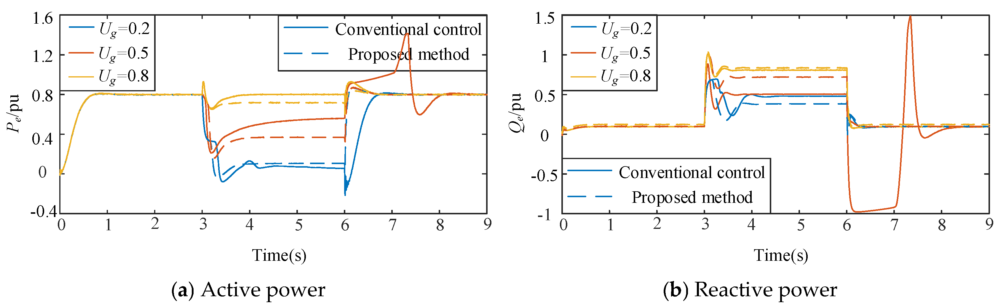
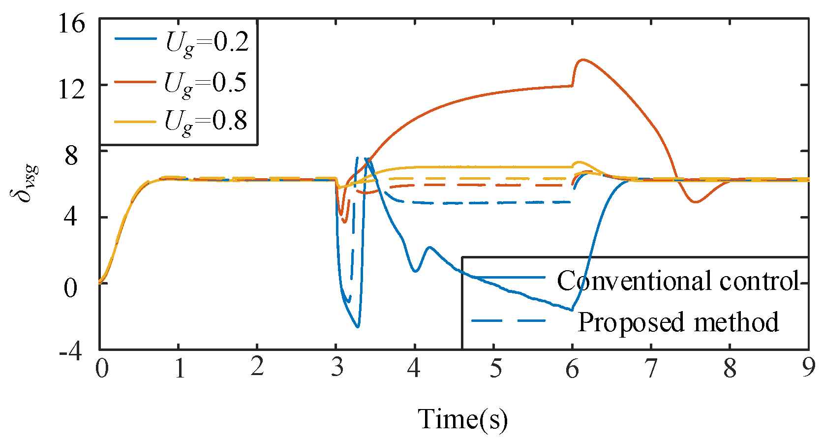
To verify the adaptability and effectiveness of the proposed control method for different voltage sag depths, the equivalent grid reactance was set to Xg = 0.5 pu. The system initially operated under normal grid-connected conditions. At t = 3 s, the grid voltage abruptly decreased; at t = 6 s, the fault was cleared, and the voltage was restored to its nominal value. To represent different fault severities, three cases were tested with the grid voltage sagging to Ug = 0.2 pu, 0.5 pu, and 0.8 pu. Figure 19 and Figure 20 show the simulation results.
Figure 19 compares the active and reactive power responses of the traditional control strategy and proposed strategy during LVRT for different sag depths. Figure 20 presents the corresponding power angle dynamics. The results demonstrated that with increasing sag depth, the power fluctuations of the traditional control strategy during fault transitions were significantly amplified. In particular, under severe sag conditions (e.g., Ug = 0.2 pu), both active and reactive power had pronounced oscillations with long recovery delays. Simultaneously, the power angle rapidly accumulated and had large deviations during the fault; even after fault clearance, convergence to the steady state was slow, which indicates weakened GFM synchronization and a heightened risk of instability.
In contrast, significantly reduced active and reactive power oscillations are achieved under different voltage sag conditions by the proposed strategy, resulting in smoother transient responses. After fault clearance, the power is rapidly restored to its steady-state value, thereby effectively avoiding sustained oscillations. Significant improvement is also achieved in the power-angle dynamic performance. Even under severe voltage sag conditions, the power-angle deviation can be effectively suppressed, and rapid convergence can be achieved after fault clearance.
To further quantitatively evaluate the dynamic adaptability of the proposed strategy under different voltage sag severities, key performance indicators, including the active-power recovery overshoot, maximum power-angle deviation, and post-fault settling time, are extracted from the simulation results. Taking the severe voltage sag condition Ug = 0.2 pu as an example, the conventional PQ-LVRT strategy suffers from a significant active-power recovery impact due to the fixed power references that cannot adapt to severe voltage constraints. The maximum active-power overshoot reaches approximately 55%, the maximum power-angle deviation is about 15 rad, and approximately 2 s is required after fault clearance for the system to return to the stable operating region.
In contrast, the proposed strategy dynamically adjusts the active-power reference according to the fault severity and coordinates the voltage recovery process through adaptive reactive-power support. As a result, the maximum active-power overshoot is reduced to approximately 20%, corresponding to a reduction of more than 60%. Meanwhile, the maximum power-angle deviation is reduced to about 8 rad, and the recovery time is shortened to approximately 1 s.

5.3. LVRT Control Comparison in Multi-VSG Scenarios

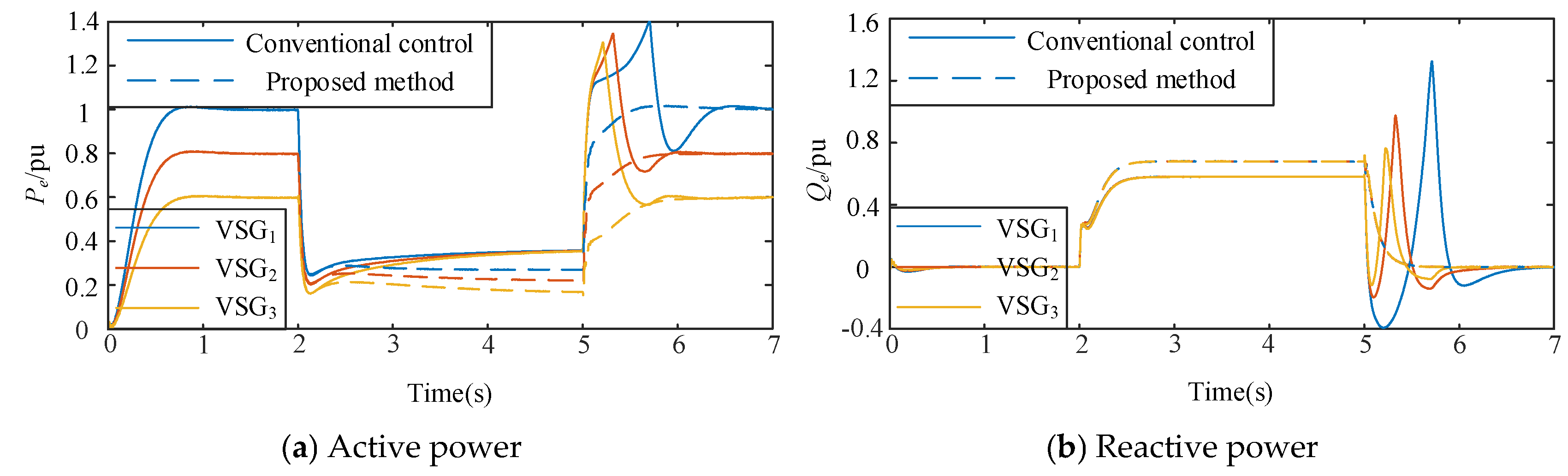
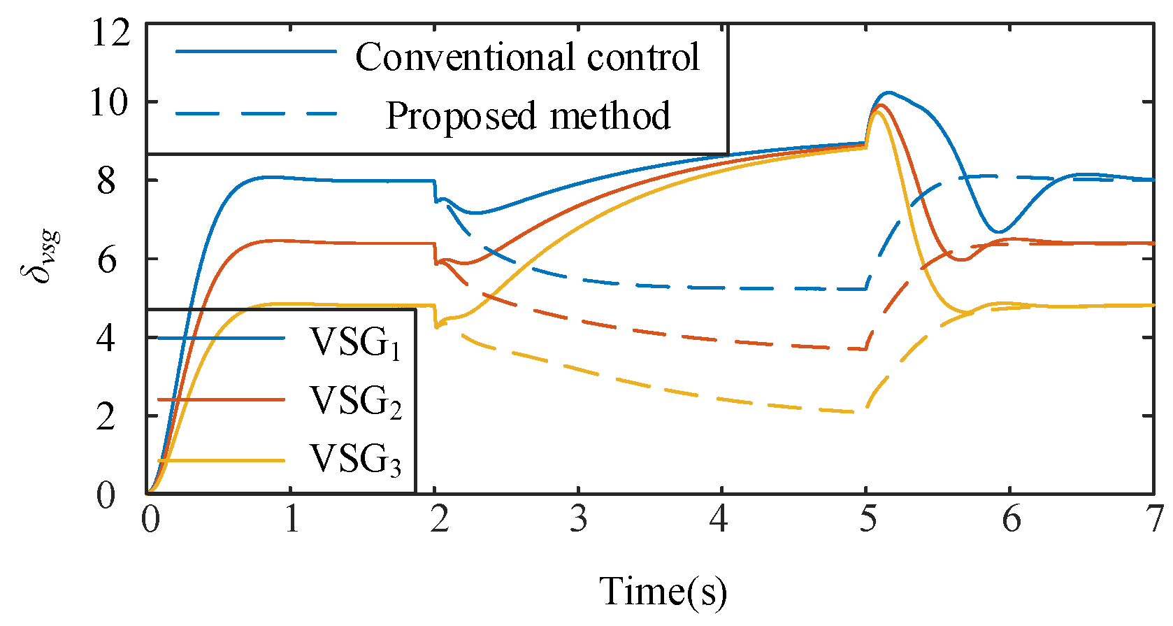
To validate the effectiveness of the proposed method in multi-machine systems during LVRT, we conducted simulations on a three-VSG parallel system. The system initially operated under normal grid-connected conditions. At t = 2 s, the grid voltage dropped to 0.4 pu; at t = 5 s, the fault was cleared, and the grid voltage was restored to its nominal value. To emphasize the weak grid characteristics, the grid reactance was set to Xg = 0.5. Figure 21 and Figure 22 show the simulation results.
Figure 21 compares the active and reactive power responses of different methods in a weak grid. As shown in Figure 21a, with the traditional strategy, the interactions among multiple units significantly amplified the active power oscillations, which caused pronounced declines and fluctuations after the voltage sag and a notably slower recovery after fault clearance. In contrast, the proposed method effectively suppressed power disturbances during the fault, produced smaller fluctuations, and enabled a rapid return to steady-state values after fault clearance, which demonstrates improved dynamic response and recovery capability.
As shown in Figure 21b, the traditional method exhibited a delayed response and considerable fluctuations in reactive power regulation; it could not easily and promptly return to the steady state after recovery. In comparison, the proposed method provided greater reactive support during the fault and quickly returned to near zero after fault clearance, which enhanced the PCC voltage support and overall system stability.
Figure 22 compares the power angle dynamics. The traditional strategy caused large power angle deviations and prolonged oscillations after fault occurrence, i.e., a potential instability risk. The proposed method significantly reduced power angle fluctuations during the fault and enabled rapid convergence to steady state after recovery, which highlight its improved synchronization stability in multi-machine systems.
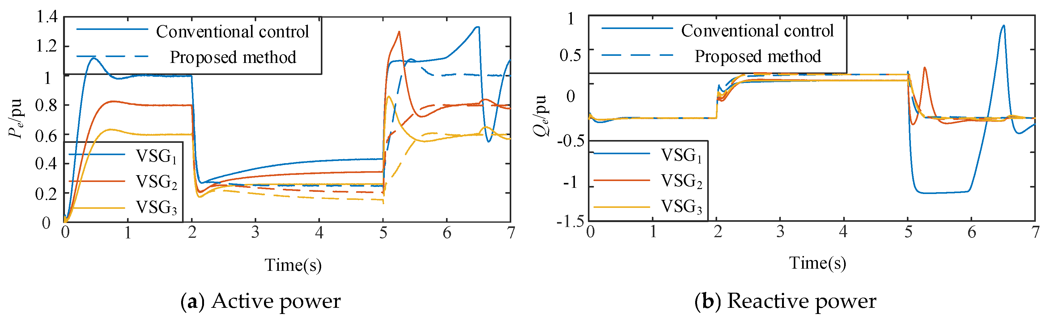
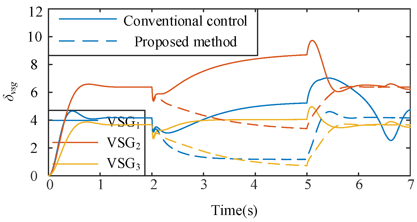
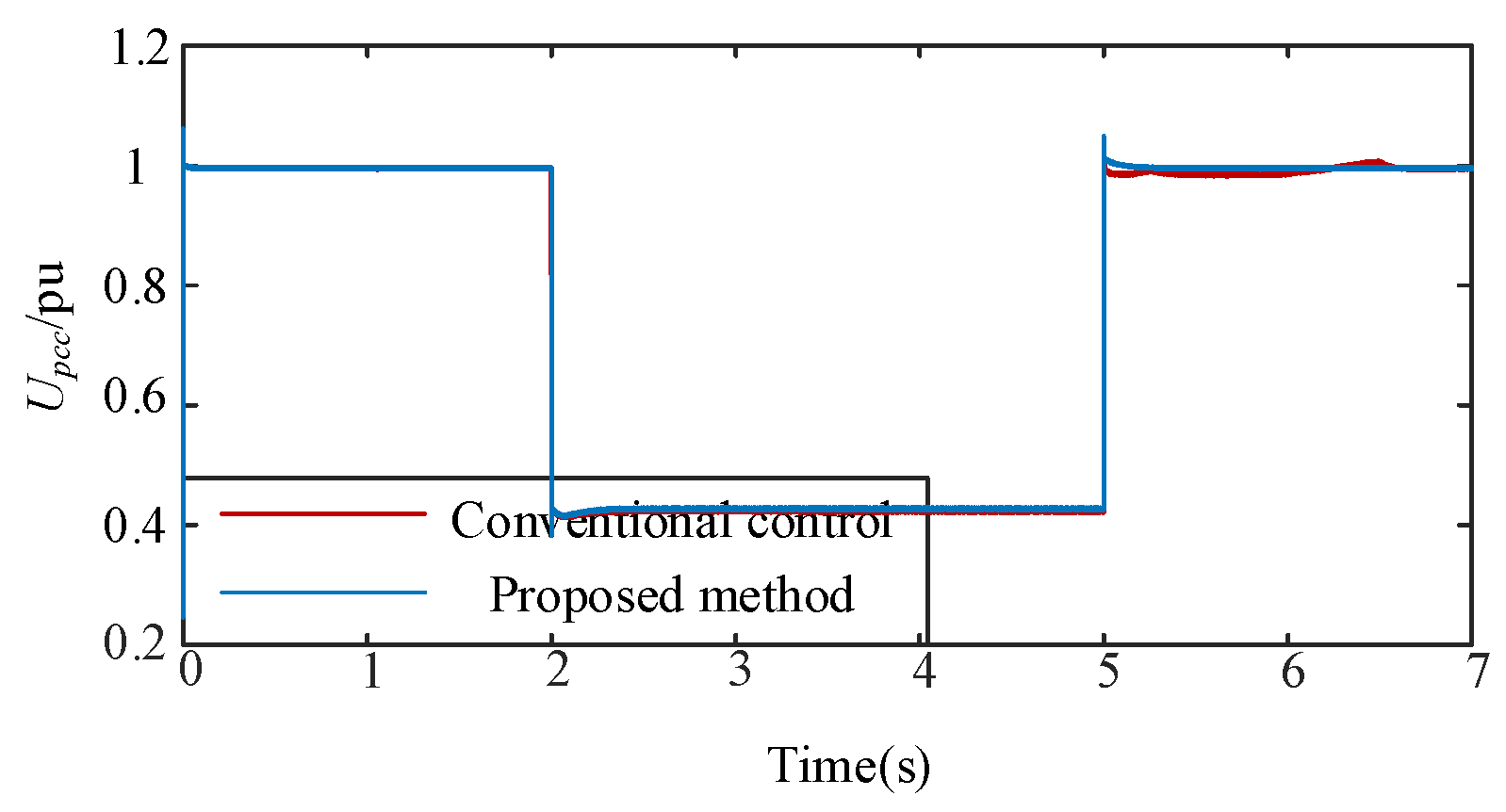
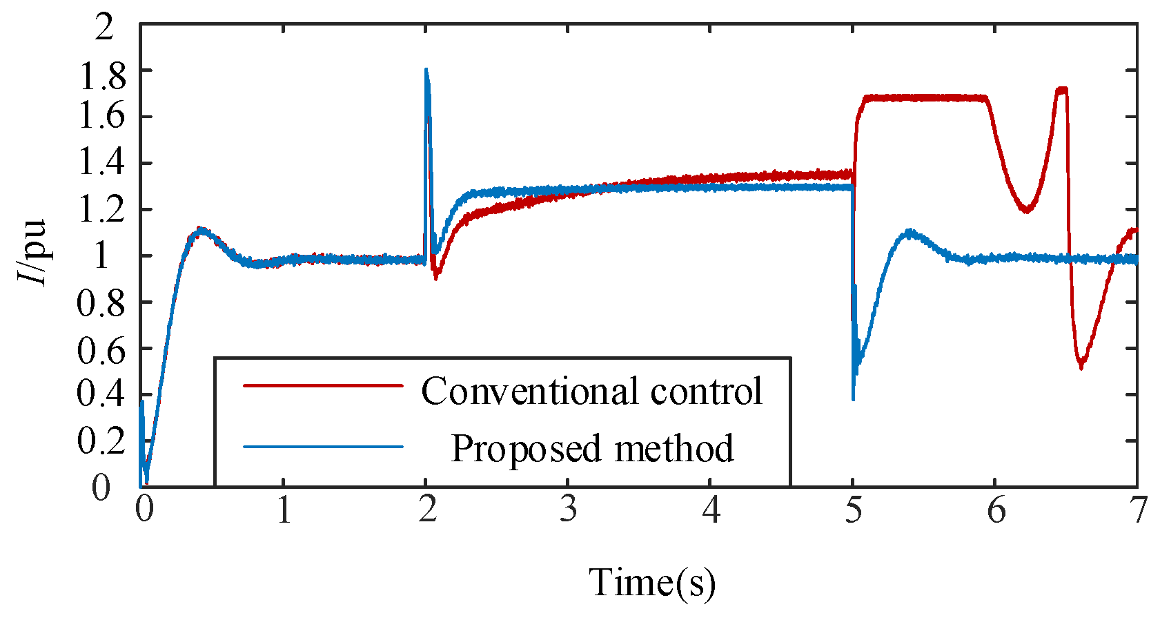
To further demonstrate the advantage of the proposed consensus-based coordination strategy under heterogeneous multi-unit conditions, simulations are carried out on a system consisting of three VSGs with different rated capacities, line impedances, and control parameters. The corresponding parameters are listed in Table 3. The system is initially operated under normal grid-connected conditions. At t = 2 s, the ac grid voltage drops to 0.4 pu, and at t = 5 s, the fault is cleared and the grid voltage is restored to its rated value. The corresponding power, power-angle, PCC voltage, and output-current responses are shown in Figure 23, Figure 24, Figure 25 and Figure 26.
As shown in Figure 23, under the conventional PQ-LVRT strategy, the active- and reactive-power references of each VSG are independently adjusted according to its local voltage and current constraints. The differences in unit capacity, line impedance, and remaining current margin are not considered. As a result, the active-power sharing among different units becomes significantly unbalanced during the fault. After the fault occurs, the active power of VSG1 decreases rapidly and exhibits a sustained deviation, while the active-power outputs of VSG2 and VSG3 also show obvious fluctuations. After fault clearance, large active-power overshoots and oscillations occur under the conventional PQ-LVRT strategy, and some units even have difficulty returning to a stable operating state. This indicates that stable LVRT cannot be effectively achieved under heterogeneous multi-VSG weak-grid conditions using the conventional strategy.
In contrast, the proposed strategy introduces a consensus-based coordination mechanism weighted by rated capacity and remaining current margin. In this way, each VSG can reasonably share the active-power recovery and reactive-power support tasks according to its own support capability during the fault. As shown in Figure 23, the active-power outputs of the three VSGs are maintained within reasonable ranges under the proposed strategy during the fault period. After fault clearance, the active power is restored more smoothly, and the power oscillations and overshoots are significantly reduced. This demonstrates that the overall fault-support capability of the multi-VSG system is more effectively utilized.
Figure 24 further shows the power-angle dynamic responses of the three heterogeneous VSGs. Under the conventional PQ-LVRT strategy, the power angles of all units continue to increase during the fault, and significant differences in power-angle deviations are observed among different units. After the fault is cleared, large power-angle oscillations still exist, indicating that a stable power-angle equilibrium point cannot be reconstructed in time and that synchronization instability may occur. In particular, under heterogeneous parameter conditions, the lack of multi-unit coordination constraints in the conventional PQ-LVRT strategy may cause accelerated power-angle accumulation in some units, making stable LVRT difficult to achieve.
With the proposed control strategy, the power-angle deviations of all VSGs are significantly reduced. The increasing trend of the power angle during the fault is effectively suppressed, and the power angles rapidly converge to a stable operating region after fault clearance. These results indicate that the proposed consensus-based coordination strategy can effectively suppress inter-unit power oscillations and power-angle deviations under heterogeneous multi-VSG conditions. It also prevents a single VSG from undertaking excessive fault-support responsibility, thereby improving the LVRT capability and transient synchronization stability of the multi-VSG system under weak-grid faults.
To further verify the voltage support capability and current-limiting performance of the proposed control strategy, the dynamic responses of the RMS voltage at the PCC and the RMS output current of VSG1 are presented in Figure 25 and Figure 26, respectively. As shown in Figure 25, after the fault occurs, the PCC voltage drops from the rated value to approximately 0.4 pu. Compared with the conventional PQ-LVRT strategy, the proposed method maintains a slightly higher PCC voltage level during the fault period and restores the voltage to around the rated value more rapidly after fault clearance. This indicates that the proposed adaptive reactive-power support strategy can improve the PCC voltage recovery process and enhance the voltage support capability during faults.
As shown in Figure 26, large current fluctuations occur under the conventional PQ-LVRT strategy during both fault occurrence and fault clearance. In particular, after fault clearance, the output current of VSG1 continues to increase and remains at a relatively high level, indicating that insufficient coordination between active-power recovery and reactive-power support may lead to severe current stress. In contrast, the proposed method effectively constrains the output current during the fault period and rapidly suppresses the current fluctuation after fault clearance, allowing the output current of VSG1 to return to a reasonable range. These results demonstrate that the proposed control strategy can effectively suppress sustained overcurrent stress and maintain the current response within an acceptable range during fault recovery.

5.4. LVRT Performance Under Single-Line-to-Ground Faults

To further verify the applicability of the proposed control strategy under practical unbalanced grid faults, a single-line-to-ground (SLG) fault scenario is considered to evaluate the LVRT performance. Unlike balanced three-phase voltage sags, SLG faults introduce negative-sequence voltage components, which may cause double-frequency oscillations in the output power of grid-connected converters. Therefore, this case study mainly focuses on the active-power recovery, reactive-power support, and post-fault dynamic stability under asymmetric fault conditions.
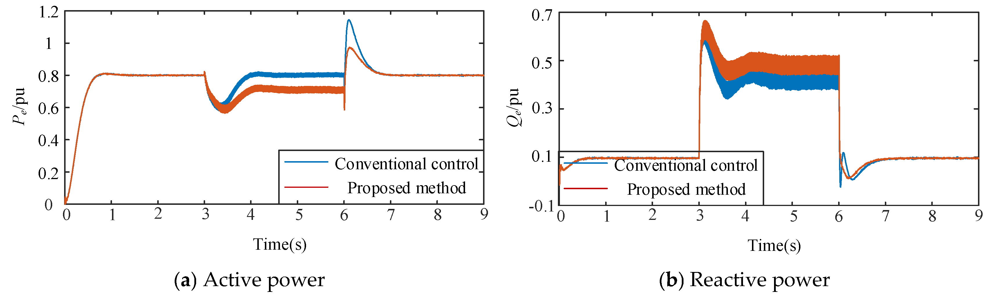
A single-VSG grid-connected system is adopted for the simulation, and the equivalent grid reactance is set to Xg = 0.5 pu to represent a typical weak-grid condition. The system initially operates under normal grid-connected conditions. At t = 3 s, an SLG fault occurs, during which the phase-A voltage decreases to approximately 0.4 pu. The fault is cleared at t = 6 s, and the grid voltage is restored to its nominal value. The conventional PQ-LVRT strategy and the proposed adaptive LVRT strategy are compared, and the corresponding active- and reactive-power responses are shown in Figure 27.
As shown in Figure 27, after the occurrence of the SLG fault, both active and reactive power outputs exhibit certain oscillations under the two control strategies due to the introduction of negative-sequence components. Compared with the conventional PQ-LVRT strategy, the proposed method effectively reduces the power oscillation amplitude during the fault period and improves the dynamic response during fault recovery.
During the initial fault stage, the conventional PQ-LVRT strategy regulates the power output based on fixed active and reactive power references, without fully considering the coupling among voltage support requirements, current constraints, and power-angle stability under unbalanced faults. Consequently, noticeable oscillations and recovery deviations occur during the active-power restoration process. In contrast, the proposed strategy dynamically adjusts the active-power reference based on the feasible operating-region constraint, thereby avoiding excessive power recovery demand during the fault period. Meanwhile, the adaptive reactive-power support strategy is incorporated to enhance voltage support capability, resulting in a smoother active-power recovery process.
Regarding the reactive-power response, the conventional PQ-LVRT strategy mainly relies on a fixed reactive-power support coefficient during the SLG fault, and its reactive-power output is jointly limited by the available current margin and fault voltage variation. In comparison, the proposed strategy adaptively adjusts the reactive-power support strength according to the fault severity, providing more stable reactive-power support while satisfying the current constraint, thereby reducing power fluctuations during the fault recovery stage.
It should be noted that, since an SLG fault introduces negative-sequence voltage components, the negative-sequence components appear as double-frequency disturbances in the positive-sequence synchronous reference frame, resulting in double-frequency oscillations in the output power. The proposed method is mainly designed to coordinate active-power recovery, voltage support, and power-angle stability during faults, and no additional negative-sequence current compensation scheme is introduced. Therefore, this case study focuses on evaluating the capability of the proposed strategy to maintain stable operation and improve fault recovery performance under unbalanced fault conditions.
To further clarify the differences between the proposed method and representative LVRT strategies, Table 4 provides a comprehensive comparison in terms of control objectives, fault-support capability, and applicable scenarios. It should be noted that different FRT methods have different design objectives and control mechanisms. For example, mode-switching-based methods mainly focus on fault current limitation, and virtual-impedance-based methods improve fault voltage stability by modifying the output impedance, while PQ-reference-based methods mainly achieve active and reactive power coordination through reference adjustment. Therefore, this paper does not aim to demonstrate that the proposed method is universally superior to all existing FRT strategies. Instead, it focuses on addressing the coordination challenge between power references and synchronization stability in PQ-reference-based VSG-FRT frameworks under weak-grid conditions.
As shown in Table 4, although conventional PQ-LVRT strategies can achieve basic current limitation and power regulation, they may fail to maintain stable power-angle equilibrium under severe voltage sags and multi-VSG coordination scenarios. Mode-switching-based methods can effectively suppress fault currents but modify the original grid-forming control structure. Virtual-impedance-based methods can improve fault current characteristics; however, their performance usually depends on impedance parameter design, and they are difficult to directly extend to coordinated power allocation among multiple VSGs. In contrast, the proposed method preserves the voltage-source characteristics of the VSG while achieving coordinated optimization among active-power recovery, reactive-power support, power-angle stability, and multi-unit coordination through feasible-region constraints, adaptive power regulation, and consensus-based coordination.

6. Conclusions

This work addressed the LVRT challenges of grid-forming VSGs under weak and extremely weak grid conditions. Compared with the selected conventional PQ-reference-based FRT benchmark, the proposed method improves power-angle stability, voltage support, and multi-VSG coordination under the tested weak-grid fault conditions. The main conclusions are as follows:
  • An equivalent voltage vector and power relationship model of the VSG during faults was established. Visual criteria for operating/feasible regions were derived. When the VSG power characteristic curve does not intersect with the grid characteristic curve, no stable operating point forms, which causes FRT failure. Moreover, a deeper voltage sag significantly shrinks the feasible region.
  • Based on the “power circle–capability cone” model, a comprehensive reactive-power capability constraint was developed by jointly considering current limitation, line reactance, and apparent-power capacity. A voltage-error-driven projection-limiting method was proposed to generate Qref. By allocating the available current margin to reactive support and coordinating it with active-power reference reduction, the proposed strategy enhances PCC voltage support, suppresses excessive current stress, and maintains the GFM characteristics and power-angle stability during LVRT.
  • The reactive droop coefficient kq simultaneously affects the feasible regions of both active and reactive power references. An adaptive voltage-dependent kq was proposed: increasing kq for shallow sags to enhance the voltage support, and reducing kq under a deep sag to maintain controllability. This result resolves the contradiction that fixed parameters cannot accommodate different fault depths.
  • A distributed consensus mechanism was introduced to coordinate the active and reactive power references of multiple VSGs during LVRT. The multi-VSG simulation results show that the proposed coordination reduces inter-unit power oscillations and improves post-fault synchronization stability.

Author Contributions

Methodology, J.L. and S.W.; software, Z.C. (Zihao Chen) and H.L.; validation, J.L., Z.C. (Zihao Chen) and Y.H.; formal analysis, J.L., X.M. and S.W.; investigation, H.L., Z.C. (Zhishan Chen) and Z.W.; data curation, Z.C. (Zihao Chen), Z.C. (Zhishan Chen) and Z.W.; writing—original draft preparation, J.L.; writing—review and editing, J.L. and S.W.; visualization, X.M., Z.C. (Zihao Chen), H.L. and Z.W.; supervision, S.W. and X.M.; project administration, J.L.; funding acquisition, J.L. All authors have read and agreed to the published version of the manuscript.

Funding

This work was supported by the National Undergraduate Innovation Training Program Project (202610579002), the School-Level Talent Special Project (ZL2530), the Zhanjiang Science and Technology Program (2025B01109), and the Zhanjiang Key Laboratory of Mangrove Ecosystem Conservation and Restoration (HSL202618).

Data Availability Statement

The data presented in this study are available on request from the corresponding author due to confidentiality agreements related to ongoing research and proprietary restrictions within the laboratory.

Conflicts of Interest

The authors declare that the research was conducted in the absence of any commercial or financial relationships that could be construed as a potential conflict of interest.

References

  1. Pei, J.; Zhao, D.; Bai, J.; Liu, C. Research on Improving Fault Ride Through capability of Grid-forming Converter Under Extremely Weak Grid and Severe fault condition. CSEE J. Power Energy Syst. 2025, 45, 9362–9375. [Google Scholar]
  2. Rosso, R.; Wang, X.; Liserre, M.; Lu, X.; Engelken, S. Grid-forming converters: An overview of control approaches and future trends. In 2020 IEEE Energy Conversion Congress and Exposition (ECCE); IEEE: Piscataway, NJ, USA, 2020; pp. 4292–4299. [Google Scholar]
  3. Li, D.; Sun, Q.; Wang, R.; Wang, P.; Sui, Z.; Wang, P. LVRT Capability Enhancement of Grid-Forming Inverters Under Current Saturation: A Dual-Reference Dynamic Cooperative Control Strategy. IEEE Trans. Power Electron. 2026, 41, 11659–11673. [Google Scholar] [CrossRef] [Scilit]
  4. Yang, Y.; Blaabjerg, F.; Wang, H. Low-voltage ride-through of single-phase transformerless photovoltaic inverters. IEEE Trans. Ind. Appl. 2013, 50, 1942–1952. [Google Scholar]
  5. Lin, J.C.; Liu, S.Q.; Wang, G. Performance Improvement of VSG Dynamic Frequency Considering DC-Side Voltage Stability. CSEE J. Power Energy Syst. 2026, 2, 864–877. [Google Scholar]
  6. Lin, J.; Liu, S. Power–Frequency–Voltage Coupled Control of Virtual Synchronous Generators in Multiterminal DC Grids. Int. J. Circuit Theory Appl. 2026. [Google Scholar] [CrossRef] [Scilit]
  7. Chen, S.; Sun, Y.; Hou, X.; Han, H.; Fu, S.; Su, M. Quantitative parameters design of VSG oriented to transient synchronization stability. IEEE Trans. Power Syst. 2023, 38, 4978–4981. [Google Scholar] [CrossRef] [Scilit]
  8. Zhao, D.; Pei, J.; Bai, J.; Liu, C. Fault ride Through Capability Enhancement Technology of GFM Converter During Asymmetric Fault Period in Very Weak Grid. CSEE J. Power Energy Syst. 2025. [Google Scholar] [CrossRef]
  9. Yuan, H.; Xin, H.; Huang, L.; Wang, Z.; Wu, D. Stability analysis and enhancement of type-4 wind turbines connected to very weak grids under severe voltage sags. IEEE Trans. Energy Convers. 2018, 34, 838–848. [Google Scholar]
  10. Lin, J.C.; Wen, Y.M.; Liu, S.Q. Adaptive VSG Control Strategy for Photovoltaic-Storage Hybrid Power Supply Systems. Int. J. Circuit Theory Appl. 2026, 54, 1434–1445. [Google Scholar]
  11. Taul, M.G.; Wang, X.; Davari, P.; Blaabjerg, F. Current Limiting Control with Enhanced Dynamics of Grid-Forming Converters During Fault Conditions. IEEE J. Emerg. Sel. Top. Power Electron. 2020, 8, 1062–1073. [Google Scholar] [CrossRef] [Scilit]
  12. Li, B.; Yang, S.; Wang, G.; Wang, G.; Hu, Y.; Zhang, X.; Hao, Z.; Chang, D.; Zhang, B. Entire Period Transient Stability of Synchronous Generators Considering LVRT Switching of Nearby Renewable Energy Sources. IEEE Trans. Power Syst. 2025, 41, 1264–1277. [Google Scholar]
  13. Zheng, T.; Chen, L.; Guo, Y.; Mei, S. Flexible unbalanced control with peak current limitation for virtual synchronous generator under voltage sags. J. Mod. Power Syst. Clean Energy 2018, 6, 61–72. [Google Scholar]
  14. Luo, R.; Gao, H.; Peng, F.; Guo, Y. An Adaptive Low-Voltage Ride-Through Method for Virtual Synchronous Generators During Asymmetrical Grid Faults. IEEE Trans. Sustain. Energy 2024, 15, 1589–1600. [Google Scholar] [CrossRef] [Scilit]
  15. Li, Q.; Ge, P.; Xiao, F.; Lan, Z.; Ge, Q. Study on fault ride-through method of VSG based on power angle and current flexible regulation. Proc. CSEE 2020, 40, 2071–2080. (In Chinese) [Google Scholar] [CrossRef]
  16. Sun, K.; Yao, W.; Wen, J.; Jiang, L. A Two-Stage Simultaneous Control Scheme for the Transient Angle Stability of VSG Considering Current Limitation and Voltage Support. IEEE Trans. Power Syst. 2022, 37, 2137–2150. [Google Scholar] [CrossRef] [Scilit]
  17. Sadeghkhani, I.; Golshan, M.E.H.; Guerrero, J.M.; Mehrizi-Sani, A. A current limiting strategy to improve fault ride-through of inverter interfaced autonomous microgrids. IEEE Trans. Smart Grid 2016, 8, 2138–2148. [Google Scholar] [CrossRef] [Scilit]
  18. Zarei, S.F.; Mokhtari, H.; Ghasemi, M.A.; Blaabjerg, F. Reinforcing fault ride through capability of grid forming voltage source converters using an enhanced voltage control scheme. IEEE Trans. Power Deliv. 2018, 34, 1827–1842. [Google Scholar] [CrossRef] [Scilit]
  19. Jiang, F.; Cheng, S.; Tu, C.; Guo, Q.; Zhu, R.; Li, X.; Liserre, M. Design consideration of a dual-functional bridge-type fault current limiter. IEEE J. Emerg. Sel. Top. Power Electron. 2019, 8, 3825–3834. [Google Scholar] [CrossRef] [Scilit]
  20. Chen, Z.; Pei, X.; Yang, M.; Peng, L.; Shi, P. A novel protection scheme for inverter-interfaced microgrid (IIM) operated in islanded mode. IEEE Trans. Power Electron. 2017, 33, 7684–7697. [Google Scholar] [CrossRef] [Scilit]
  21. Li, Z.; Chan, K.W.; Hu, J.; Or, S.W. An adaptive fault ride-through scheme for grid-forming inverters under asymmetrical grid faults. IEEE Trans. Ind. Electron. 2021, 69, 12912–12923. [Google Scholar] [CrossRef] [Scilit]
  22. Zhuang, K.; Xin, H.; Hu, P.; Wang, Z. Current Saturation Analysis and Anti-Windup Control Design of Grid-Forming Voltage Source Converter. IEEE Trans. Energy Convers. 2022, 37, 2790–2802. [Google Scholar] [CrossRef] [Scilit]
  23. Rokrok, E.; Qoria, T.; Bruyere, A.; Francois, B.; Guillaud, X. Transient Stability Assessment and Enhancement of Grid-Forming Converters Embedding Current Reference Saturation as Current Limiting Strategy. IEEE Trans. Power Syst. 2022, 37, 1519–1531. [Google Scholar] [CrossRef] [Scilit]
  24. Me, S.P.; Zabihi, S.; Blaabjerg, F.; Bahrani, B. Adaptive virtual resistance for postfault oscillation damping in grid-forming inverters. IEEE Trans. Power Electron. 2021, 37, 3813–3824. [Google Scholar] [CrossRef] [Scilit]
  25. Liu, J.; Miura, Y.; Bevrani, H.; Ise, T. Enhanced virtual synchronous generator control for parallel inverters in microgrids. IEEE Trans. Smart Grid 2016, 8, 2268–2277. [Google Scholar] [CrossRef] [Scilit]
  26. Lin, J.C.; Liu, S.Q.; Tian, M.; Huang, M.; Wang, G. Power oscillation suppression of multi-VSG based on both consensus and model predictive control. Int. J. Electr. Power Energy Syst. 2024, 155, 109459. [Google Scholar] [CrossRef] [Scilit]
  27. Lin, J.C.; Li, X. Distributed Cooperative Control Based on Consensus Interaction for Seamless Transition of Multiple VSGs. IEEJ Trans. Electr. Electron. Eng. 2026. [Google Scholar] [CrossRef] [Scilit]
Figure 1. Grid-connected control structure of the VSG.
Electronics 15 04029 g001
Figure 2. Equivalent voltage vector diagram of the VSG.
Electronics 15 04029 g002
Figure 3. Operating region of the VSG under normal operation.
Electronics 15 04029 g003
Figure 4. Operating region of the VSG under different fault conditions.
Electronics 15 04029 g004
Figure 5. Operating regions of the VSG under different equivalent grid impedances.
Electronics 15 04029 g005
Figure 6. Vector decomposition under different idmax.
Electronics 15 04029 g006
Figure 7. Feasible region for fault ride-through.
Electronics 15 04029 g007
Figure 8. Fault region classification.
Electronics 15 04029 g008
Figure 9. Schematic diagram of the power circle and capability cone.
Electronics 15 04029 g009
Figure 10. Impact of different reactive power droop coefficients on VSG fault region classification.
Electronics 15 04029 g010
Figure 11. Adaptive droop curve with parameter perturbation band.
Electronics 15 04029 g011
Figure 12. Feasible parameter region of the adaptive droop coefficients under monotonicity, current-limit, and LVRT stability constraints.
Electronics 15 04029 g012
Figure 13. VSG operating regions under the proposed strategy for different voltage sags.
Electronics 15 04029 g013
Figure 14. Multi-VSG parallel grid-connected model.
Electronics 15 04029 g014
Figure 15. Active and reactive power output comparison under different grid strengths.
Electronics 15 04029 g015
Figure 16. Power angle dynamics under different grid strengths.
Electronics 15 04029 g016
Figure 17. RMS voltage responses at the PCC under different grid strengths.
Electronics 15 04029 g017
Figure 18. Output current magnitude responses under different grid strengths.
Electronics 15 04029 g018
Figure 19. Comparison of active and reactive power outputs under different voltage sag depths.
Electronics 15 04029 g019
Figure 20. Comparison of power angle dynamics under different voltage sag depths.
Electronics 15 04029 g020
Figure 21. Power output comparison in a weak grid.
Electronics 15 04029 g021
Figure 22. Power angle dynamics in a weak grid.
Electronics 15 04029 g022
Figure 23. Power output comparison of three heterogeneous VSGs.
Electronics 15 04029 g023
Figure 24. Power angle dynamics of three heterogeneous VSGs.
Electronics 15 04029 g024
Figure 25. RMS voltage response at the PCC.
Electronics 15 04029 g025
Figure 26. Output current magnitude of VSG1 under heterogeneous multi-VSG conditions.
Electronics 15 04029 g026
Figure 27. Active and reactive power responses under single-line-to-ground fault.
Electronics 15 04029 g027
Table 1. Initial Parameters.
ParameterVSG
Rated capacity Sn(MW)1
Rated AC line voltage (kV)0.69
Rated DC voltage (kV)1.38
Filter inductance (pu)0.13
Filter capacitance (pu)0.022
Equivalent grid reactance Xg (pu)0.7
Equivalent grid resistance Rg (pu)0.02
Transformer impedance (pu)0.087
Virtual inertia J (pu)47.1
Damping coefficient D (pu)565.4
Frequency droop coefficient Kf (pu)0.8
Voltage droop coefficient Kv (pu)0.2
Reactive power droop coefficient kq (pu)1.98
Table 2. Control Parameters of the Proposed Strategy.
ParameterValue
Adaptive droop coefficient a−1.2
Adaptive droop coefficient b1.5
Adaptive droop coefficient c−0.3
Adaptive droop coefficient d0.37
Ramp-rate coefficient Rp00.15
Voltage sensitivity coefficient m2
Stability margin coefficient γ0.9
Voltage-support coefficient α0.7
Voltage-support coefficient β0.3
Consensus step-size η0.05
Table 3. Parameters of Heterogeneous VSGs.
ParameterVSG1VSG2VSG3
Rated capacity1.0 MW0.8 MW1.2 MW
Line reactance0.06 pu0.132 pu0.09 pu
Virtual inertia J47.14252
Damping coefficient D565.4520600
Table 4. Comparison of Representative LVRT Strategies. (Note: “√” indicates the presence of the corresponding feature, whereas “×” indicates its absence.)
MethodCurrent LimitingVoltage SupportPower-Angle StabilityAdaptive ParameterMulti-VSG Coordination
Mode-switching FRT [11,12]MediumMedium××
Virtual impedance FRT [15,16]GoodGood×
Conventional PQ-LVRTMediumPoor××
Proposed methodHighHigh
Disclaimer/Publisher’s Note: The statements, opinions and data contained in all publications are solely those of the individual author(s) and contributor(s) and not of MDPI and/or the editor(s). MDPI and/or the editor(s) disclaim responsibility for any injury to people or property resulting from any ideas, methods, instructions or products referred to in the content.