Article

Switched Bang–Bang Funnel Control for Fault Ride-Through Enhancement of Doubly-Fed Variable-Speed Pumped Storage Units


1
Energy Storage Research Institute, China Southern Power Grid Power Generation Co., Ltd., Guangzhou 511499, China
2
Shenzhen Hopewind Electric Co., Ltd., Shenzhen 518055, China
3
Overhaul and Testing Branch, China Southern Power Grid Power Generation Co., Ltd., Guangzhou 511499, China
4
School of Electric Power Engineering, South China University of Technology, Guangzhou 510640, China
*
Author to whom correspondence should be addressed.
Electronics 2026, 15(11), 2356; https://doi.org/10.3390/electronics15112356
Submission received: 30 April 2026 / Revised: 26 May 2026 / Accepted: 27 May 2026 / Published: 29 May 2026

Abstract

This study addresses fault ride-through of doubly-fed pumped storage units by proposing switched bang–bang funnel controllers for machine- and grid-side converters. The objective is to enhance transient stability, current regulation, and DC-link voltage support during severe AC grid faults. The method combines funnel-based error constraints with a switching logic that activates a bang–bang action only when tracking errors approach prescribed performance bounds, reverting to nominal regulation otherwise. High-fidelity electromagnetic transient simulations are conducted and benchmarked against a conventional PI-based controller under three-phase-to-ground fault scenarios. The results show that the switched controller achieves faster active/reactive power recovery with reduced overshoot, markedly suppresses current oscillations on both converters, and limits DC-link voltage dips while shortening the voltage restoration time. The switched controller also prevents the pumped storage unit operating in pumping mode from becoming unstable in the case of a metallic fault scenario. These findings indicate that the proposed strategy improves dynamic performance and fault ride-through capability without compromising steady-state behavior, providing a practical pathway toward compliance with grid-code requirements for pumped storage units under severe disturbances.

1. Introduction

Fault ride-through capability is a critical requirement for modern power systems [1], especially with the increasing integration of renewable energy sources and the need for grid stability. Doubly-fed pumped storage units play a vital role in providing grid support and energy storage, but they are also susceptible to disturbances during AC grid faults [2]. Overcurrent during AC grid faults can lead to severe damage to the machine and converters, and voltage dips can cause instability in the system [3]. Therefore, developing effective control strategies to enhance fault ride-through capability is essential for ensuring the reliability and resilience of power systems [4,5].
In existing studies, fault ride-through (FRT) control strategies for doubly-fed pumped storage units can be broadly categorized into passive and active approaches. Passive control strategies typically employ hardware protection circuits such as Crowbar or resistors to limit fault currents. Ref. [6] pointed out that the conventional Crowbar solution suffers from an excessive activation period (191 ms under an 80% voltage dip), leading to high reactive power absorption and severe electromagnetic torque oscillations. The advantage of this method is its simplicity and reliability, but its disadvantages include loss of controllability during the fault and prolonged torque stress on the drivetrain.
Active control strategies utilize advanced algorithms to regulate rotor currents and stator flux without disconnecting the converter. They can be further divided into model-based and model-free approaches.
The existing model-based active control can be summarized as follows. Ref. [7] proposed a dynamic flux linkage control loop for grid-forming doubly-fed pumped storage units. By dynamically adjusting the proportional coefficient of the flux loop, the stator flux decay time is reduced from 100 ms to 40 ms under an 80% symmetrical fault, and reactive power reaches the rated value within 150 ms. However, the fixed control parameters still limit the transient performance under severe faults. Ref. [8] presented an optimization-based control to enhance reactive power support. By fully utilizing the rotor-side converter (RSC) capacity and reducing active power output during faults, the reactive current injection is improved by approximately 10% (from 1.05 p.u. to 1.15 p.u. in generating mode) while maintaining a 0.3 p.u. active current. The disadvantage is the high computational burden of real-time optimization, which may affect the response speed. Ref. [9] developed a virtual inductance control combined with DC-link voltage boosting. The strategy increases the RSC’s voltage margin by raising the DC-link voltage from 6.4 kV to 9.0 kV (a factor of 1.4), extending the allowable virtual inductance range. Under an 80% voltage dip and slip of 0.07, the rotor current peak is limited to only 3–14% above the nominal value, compared to 24–31% under conventional demagnetization control. However, this method lacks a coordination mechanism between the virtual inductance and the DC-boosting, and its performance under unbalanced faults has not been validated.
With respect to the model-free active control, bang–bang control offers a fast response and robustness to uncertainties [10], but its application to FRT of doubly-fed pumped storage units has not been explored. The main challenge lies in designing a switching logic that balances transient performance and steady-state behavior. Observer-based bang–bang control [11] can estimate system states in real-time, but the observer design is complex and may require extensive tuning.
The existing literature also proposes supplementary control of the pumped storage units for frequency regulation. Ref. [12] proposed a two-level coordinated power control strategy for multiple variable-speed pumped storage units participating in primary frequency regulation. Using model predictive control at the upper level and consistency control at the lower level, the frequency nadir is reduced from 0.35 Hz (GA-based control) to 0.24 Hz. The rotor speed standard deviation among units is decreased from 0.02 p.u. to 0.006 p.u. However, the study did not evaluate the controller’s performance during severe AC grid faults. Ref. [13] conducted a small-signal frequency stability analysis for power grids integrated with variable-speed pumped storage units. The Nyquist stability criterion showed that unstable operation can occur when compensation parameters such as temporary droop gain R T are too low (e.g., R T = 0.08 ). The study focused on small-signal stability rather than transient FRT performance.
From the above review, it can be observed that existing studies have not fully explored the potential of model-free control strategies, such as bang–bang control, for enhancing the FRT capability of doubly-fed pumped storage units. The faster reaction speed of power electronic converters has not been fully utilized, and the maximum control effect of the controllers has not been exploited. Moreover, the coordination mechanism between different control loops (e.g., virtual inductance and DC-boosting) and the impact of the control strategy on transient performance during severe faults have not been adequately addressed. Therefore, there is a need for further research to develop novel control strategies that can effectively enhance the FRT capability while ensuring system safety and reliability.
Table 1 summarizes the existing FRT strategies and their characteristics. Existing active control methods are predominantly model-based and rely on fixed parameters or optimization algorithms that may not fully exploit the converter’s speed or achieve maximum transient performance. Model-free approaches (bang–bang, observer-based) remain largely unexplored for doubly-fed variable-speed pumped storage units. Furthermore, no prior work has proposed a coordinated virtual inductance and DC-boosting scheme with adaptive switching logic that can simultaneously limit rotor overcurrent, provide reactive support, and minimize torque oscillations during severe symmetrical faults. This gap motivates the research presented in this paper.
This paper proposes a novel bang–bang control strategy for enhancing fault ride-through capability of doubly-fed pumped storage units. The main contributions of this paper are as follows:
  • A three-value bang–bang funnel control strategy is proposed for the machine-side converter, and a two-value bang–bang funnel control strategy is designed for the grid-side converters of the doubly-fed pumped storage unit, which can provide fast response and robustness to uncertainties during severe AC grid faults.
  • A switching logic is designed to activate the bang–bang funnel controllers only when the tracking errors of the control loops approach the prescribed performance bounds, while reverting to nominal regulation otherwise, thus effectively balancing the trade-off between transient performance and steady-state behavior.
  • High-fidelity electromagnetic transient simulations are conducted to evaluate the performance of the proposed control strategy under three-phase-to-ground fault scenarios in both generating mode and pumping mode, and are benchmarked against a conventional PI-based controller.
Based on the simulation results, the proposed switched bang–bang funnel control system significantly outperforms conventional PI controllers. The bang–bang funnel controller not only helps to achieve faster fault ride-through, but also can be used in fast starting and braking of the pumped storage unit, which is a topic of future research [14].
Overall, this paper is organized as follows. Section 2 describes the system topology and mathematical model of the doubly-fed pumped storage unit. Section 3 presents the design of the switched bang–bang funnel controllers for the machine-side and grid-side converters. Section 4 provides the simulation results and performance evaluation of the proposed control strategy under severe AC grid faults. Finally, Section 5 concludes the paper and discusses future research directions.

2. System Description

2.1. System Topology

The topology of the doubly-fed pumped storage unit studied in this work is as shown in Figure 1. The topology of the doubly-fed pumped storage unit consists of a hydraulic turbine connected to a doubly-fed induction generator via a common shaft. Water flow drives the turbine blades, which in turn rotate the rotor, while the stator is directly coupled to the grid. The rotor winding is fed through a back-to-back converter comprising a machine-side converter (MSC) and a grid-side converter (GSC), with DC-link capacitors C m and C g for voltage smoothing and energy buffering. The MSC regulates the rotor current to control the generator’s active power and reactive power measured from the stator side, while the GSC maintains DC-link voltage and manages reactive power exchange with the external AC grid. This configuration enables variable-speed operation in both pumping and generating modes, enhancing the overall efficiency and grid support capability. The rated capacity of the generator is 896 MVA in the generating mode, and 892 MVA in the pumping mode. The rated frequency of the system is 50 Hz, and the nominal phase-to-ground RMS voltage on the stator side is 20 kV.
In the illustrated doubly-fed pumped storage system, the back-to-back converter between the machine side and the grid side is implemented as a three-level neutral-point-clamped (NPC) converter, where the DC-link is split by capacitors C m and C g to provide a three-level voltage output per phase. This three-level topology offers several key advantages for this application [15]: it significantly reduces harmonic distortion on both the rotor and grid sides because the multilevel switching produces a voltage waveform much closer to a sinusoid, thereby minimising the need for large filters; it lowers the d v / d t and voltage stress on the generator windings and bearings, which improves machine reliability; for a given switching loss budget, the effective output frequency is higher, or conversely, the converter can operate at a lower switching frequency while maintaining excellent power quality, thus reducing switching losses; the three-level structure allows the system to work at higher DC-link voltages without requiring series-connected devices, making it well suited for megawatt-scale pumped storage plants; and overall, the lower switching and filter losses contribute to higher efficiency, which is especially beneficial for plants that frequently cycle between pumping and generating modes. Consequently, the three-level back-to-back converter enables smooth variable-speed operation, better grid power quality, and enhanced robustness in the doubly-fed pumped storage unit.

2.2. Mathematical Model of the System

For controller design purpose, the doubly-fed pumped storage unit is modeled as follows. In the dq rotational reference frame, the stator and rotor winding voltage equations of the induction machine are given as [16]
v ds = R s i ds + p ψ ds ω ψ qs v qs = R s i qs + p ψ qs + ω ψ ds v dr = R r i dr + p ψ dr s ω ψ qr v qr = R r i qr + p ψ qr + s ω ψ dr
Let v n denote the rated phase-to-ground voltage in Volts, i n be the rated current in Amperes, and ψ n be the rated flux in Webers. The above equations can be normalized as
v ¯ ds = R ¯ s i ¯ ds + p ψ ¯ ds / ω n ω ¯ ψ ¯ qs v ¯ qs = R ¯ s i ¯ qs + p ψ ¯ qs / ω n + ω ¯ ψ ¯ ds v ¯ dr = R ¯ r i ¯ dr + p ψ ¯ dr / ω n s ω ¯ ψ ¯ qr v ¯ qr = R ¯ r i ¯ qr + p ψ ¯ qr / ω n + s ω ¯ ψ ¯ dr
where v n = i n Z n = ψ n ω n , and s = ( ω ω r ) / ω . The stator and rotor flux linkages can be expressed as
ψ ¯ ds = L ¯ s i ¯ ds + L ¯ m i ¯ dr ψ ¯ qs = L ¯ s i ¯ qs + L ¯ m i ¯ qr ψ ¯ dr = L ¯ m i ¯ ds + L ¯ r i ¯ dr ψ ¯ qr = L ¯ m i ¯ qs + L ¯ r i ¯ qr
where L ¯ s = L ¯ ls + L ¯ m and L ¯ r = L ¯ lr + L ¯ m .
The rotational equations of the lumped masses of the turbine and generator can be written as
H v d ω r d t = π f n T ¯ m T ¯ e Δ ω r 2 π f n
where Δ ω r = ω r ω n , H v = H t / N c + H g , D = e T w / N c + D g , and e T w = T m / ω r . The electromechanical torque of the generator can be expressed as
T ¯ e = ψ ¯ ds i ¯ qs ψ ¯ qs i ¯ ds
In the design of the excitation controller of the pumped storage unit, the dynamics of the stator flux linkages are neglected, i.e., p ψ ¯ ds = p ψ ¯ qs = 0 , and then the stator voltage equations can be rewritten as
v ¯ ds = R ¯ s i ¯ ds ω ¯ ψ ¯ qs v ¯ qs = R ¯ s i ¯ qs + ω ¯ ψ ¯ ds
With the above equations, the stator currents can be obtained as
i ¯ ds = [ R ¯ s ( v ¯ ds + ω ¯ L ¯ m i ¯ qr ) + ω ¯ L ¯ s ( v ¯ qs ω ¯ L ¯ m i ¯ dr ) ] / [ R ¯ s 2 + ω ¯ 2 L ¯ s 2 ] i ¯ qs = [ R ¯ s ( v ¯ qs ω ¯ L ¯ m i ¯ dr ) ω ¯ L ¯ s ( v ¯ ds + ω ¯ L ¯ m i ¯ qr ) ] / [ R ¯ s 2 + ω ¯ 2 L ¯ s 2 ]
Moreover, the derivative of the stator currents can be obtained as
p i ¯ ds = L ¯ m p i ¯ dr / L ¯ s p i ¯ qs = L ¯ m p i ¯ qr / L ¯ s
Substituting (7) and (8) into the last two equations of (2), the rotor voltage equations can be rewritten as
d i ¯ dr d t = ω n L ¯ s L ¯ s L ¯ r L ¯ m 2 v ¯ dr R ¯ r i ¯ dr s ω ¯ L ¯ m 2 L ¯ s L ¯ r L ¯ s i ¯ qr s L ¯ m L ¯ s v ¯ ds d i ¯ qr d t = ω n L ¯ s L ¯ s L ¯ r L ¯ m 2 v ¯ qr R ¯ r i ¯ qr s ω ¯ L ¯ m 2 L ¯ s L ¯ r L ¯ s i ¯ dr
where we have assumed the following:
  • The stator resistance is negligible compared to the reactance of the stator, i.e., R ¯ s ω ¯ L ¯ s , and R ¯ s 0 .
  • The PLL is ideal, and the d-axis of the dq reference frame is aligned to the stator voltage vector, and therefore, it has v ¯ qs = 0 .
With the above assumptions, the electromagnetic torque can be expressed as
T ¯ e = L ¯ m ω ¯ L ¯ s v ¯ ds i ¯ dr
and the stator active and reactive power output of the generator can be obtained as
P ¯ s = L ¯ m ω ¯ L ¯ s v ¯ ds i ¯ dr Q ¯ s = 1 ω ¯ L ¯ s v ¯ ds 2 + L ¯ m L ¯ s v ¯ ds i ¯ qr
Letting the current flowing into the grid-side converter be positive, the current dynamics of the grid-side converter can be expressed as
d i ¯ dg d t = ω n L ¯ g v ¯ ds v ¯ dg R ¯ g i ¯ dg + ω ¯ L ¯ g i ¯ qg d i ¯ qg d t = ω n L ¯ g v ¯ qg R ¯ g i ¯ qg ω ¯ L ¯ g i ¯ dg
With the above system model, the control system for the doubly-fed pumped storage unit is designed in the next section.

3. Control System Design

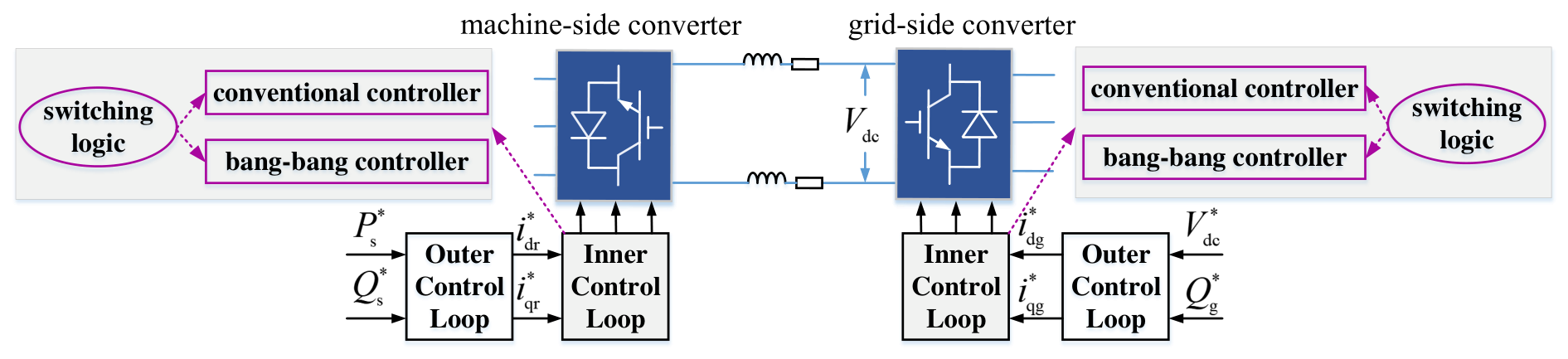
The layout of the control system for the back-to-back converters of the pumped storage unit is as shown in Figure 2. Both the controller of GSC and the MSC employ a two-loop structure. The outer control loop of the GSC is designed to regulate the DC-link voltage and the reactive power exchange with the grid, and generates current references for the inner control loop. The outer control loop of the MSC is designed to regulate the active power output of the stator and the reactive power exchange with the grid, and generates current references for the inner control loop. The inner control loops of GSC and MSC are realized by a switching mechanism, e.g., the conventional PI controller is operated in a switched manner with a bang–bang funnel controller in each control loop based on a hybrid switching strategy. A PLL is used to synchronize the d-axis of the dq reference frame to the stator voltage vector, and the frequency generated by the PLL is used as the reference frequency for the control system of the back-to-back converters. The detailed design of each control loop and the switching strategy are described in the following subsections. For ease of presentation, the · ¯ notation of the per unit variables is omitted in the following sections.

3.1. Conventional PI Control Loops

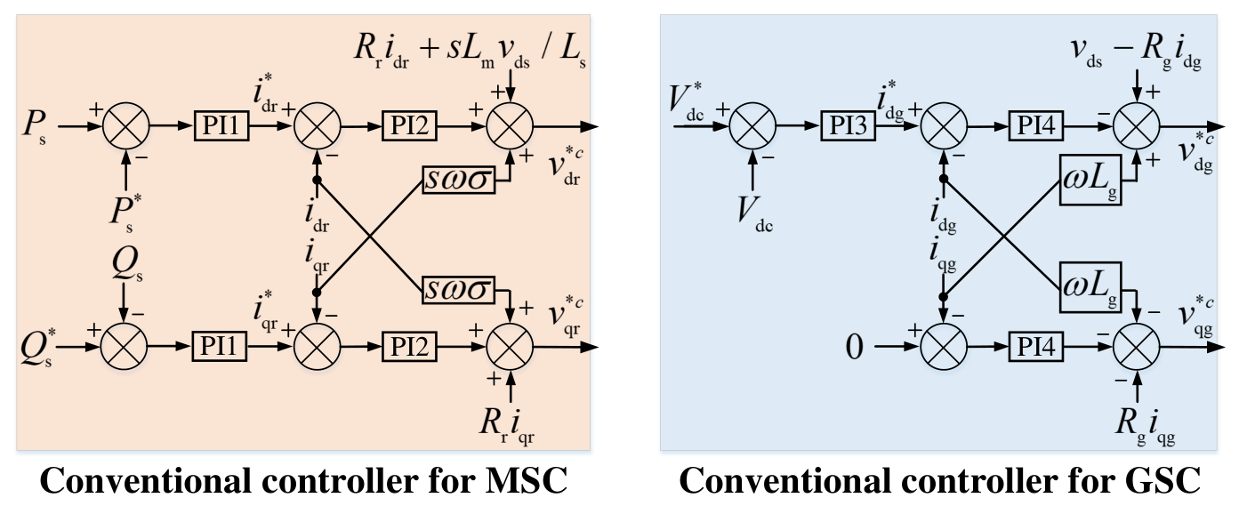
The structure of the conventional PI control loops for the GSC and MSC are as shown in Figure 3. The PI controllers are designed based on the linearized system model, and the controller parameters are tuned by frequency scanning to ensure the stability of the closed-loop system. With respect to the GSC, the reference for the d-axis current is generated by the DC-link voltage control loop, and the reference for the q-axis current is generated by the reactive power control loop. With respect to the MSC, the reference for the d-axis current is generated by the active power control loop, and the reference for the q-axis current is generated by the reactive power control loop. The inner control loops of both GSC and MSC are designed to track the current references by a PI controller and feedforward compensation, respectively.

3.2. Bang–Bang Funnel Control Loops

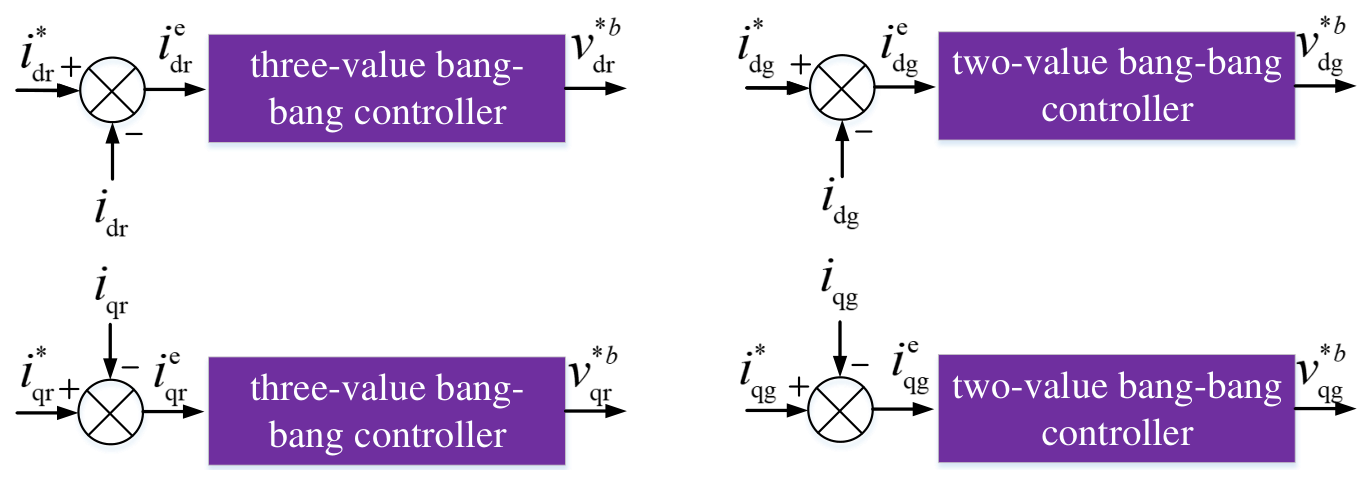
The bang–bang funnel controllers are employed in each inner current control loop of the GSC and MSC, and the structure of the bang–bang funnel controller is as shown in Figure 4. The funnel controller is designed based on the nonlinear system model, and the controller parameters are tuned by time-domain simulations to ensure the stability of the closed-loop system. The funnel controller is designed to guarantee that the tracking error of the current control loop converges to a predefined funnel boundary, which is a time-varying function that defines a performance envelope for the tracking error. The bang–bang nature of the controller allows for fast convergence to the funnel boundary, while also providing robustness against model uncertainties and external disturbances.
Three-value bang–bang funnel controllers are designed for the inner current control loops of MSC, where the control input can take three values: a positive-effect value to drive the tracking error towards the upper boundary of the funnel, a negative-effect value to drive the tracking error towards the lower boundary of the funnel, and a zero-effect value when the tracking error is within the funnel boundaries. Specifically, the control logic of the three-value bang–bang funnel controller can be described as follows:
Firstly, with respect to the tracking error i dr e ( t ) of the MSC, the bang–bang control scheme is defined as
v dr b ( t ) = v dr 0 ( t ) + Δ v dr + if q i dr e ( t ) = 1 v dr 0 ( t ) , if q i dr e ( t ) = 0 v dr 0 ( t ) + Δ v dr , if q i dr e ( t ) = + 1
where the logic variable q i dr e ( t ) is defined as
q i dr e ( t ) = + 1 , if i dr e ( t ) ρ i dr e + ( t ) ( q i dr e old = 1 i dr e ( t ) > 0 ) 0 , if i dr e ( t ) = 0 ( q i dr e old = 0 ρ i dr e ( t ) < i dr e ( t ) < ρ i dr e + ( t ) ) 1 , if i dr e ( t ) ρ i dr e ( t ) ( q i dr e old = 1 i dr e ( t ) < 0 )
According to the first equation of (9), the coefficient ω n L s / ( L s L r L m 2 ) of the control input v dr is positive, and therefore, when the tracking error i dr e is above the upper boundary of the funnel, i.e., q i dr e ( t ) = 1 , the control input should be negative to drive the tracking error towards the upper boundary of the funnel, and therefore, Δ v dr < 0 . When the tracking error i dr e is below the lower boundary of the funnel, i.e., q i dr e ( t ) = 1 , the control input should be positive to drive the tracking error towards the lower boundary of the funnel, and therefore, Δ v dr + > 0 . When the tracking error i dr e is within the funnel boundaries, i.e., q i dr e ( t ) = 0 , no additional control action is needed, and therefore, v dr b ( t ) = v dr 0 ( t ) . v dr 0 ( t ) is obtained by the steady-state power flow solution of the system, i.e.,
v dr 0 ( t ) = R r i dr ( t ) + s ω L m 2 L s L r L s i qr ( t ) + s L m L s v ds ( t )
Secondly, with respect to the tracking error i qr e ( t ) of the MSC, the bang–bang control scheme is defined as
v qr b ( t ) = v qr 0 ( t ) + Δ v qr + if q i qr e ( t ) = 1 v qr 0 ( t ) , if q i qr e ( t ) = 0 v qr 0 ( t ) + Δ v qr if q i qr e ( t ) = + 1
where the logic variable q i qr e ( t ) is defined as
q i qr e ( t ) = + 1 , if i qr e ( t ) ρ i qr e + ( t ) ( q i qr e old = 1 i qr e ( t ) > 0 ) 0 , if i qr e ( t ) = 0 ( q i qr e old = 0 ρ i qr e ( t ) < i qr e ( t ) < ρ i qr e + ( t ) ) 1 , if i qr e ( t ) ρ i qr e ( t ) ( q i qr e old = 1 i qr e ( t ) < 0 )
According to the second equation of (9), the coefficient ω n L s / ( L s L r L m 2 ) of the control input v qr is positive, and therefore, when the tracking error i qr e is above the upper boundary of the funnel, i.e., q i qr e ( t ) = 1 , the control input should be negative to drive the tracking error towards the upper boundary of the funnel, and therefore Δ v qr < 0 . When the tracking error i qr e is below the lower boundary of the funnel, i.e., q i qr e ( t ) = 1 , the control input should be positive to drive the tracking error towards the lower boundary of the funnel, and therefore, Δ v qr + > 0 . When the tracking error i qr e is within the funnel boundaries, i.e., q i qr e ( t ) = 0 , no additional control action is needed, and therefore, v qr b ( t ) = v qr 0 ( t ) . v qr 0 ( t ) is obtained by the steady-state power flow solution of the system, i.e.,
v qr 0 ( t ) = R r i qr ( t ) + s ω L m 2 L s L r L s i dr ( t )
Two-value bang–bang funnel controllers are designed for the inner current control loops of GSC, where the control input can take two values: a positive-effect value to drive the tracking error towards the upper boundary of the funnel, and a negative-effect value to drive the tracking error towards the lower boundary of the funnel. The control logic of the two-value bang–bang funnel controller can be described as follows:
Firstly, with respect to the tracking error i dg e ( t ) of the GSC, the bang–bang control scheme is defined as
v dg b ( t ) = v dg 0 ( t ) + Δ v dg + , if q i dg e ( t ) = + 1 v dg 0 ( t ) + Δ v dg , if q i dg e ( t ) = 1
where the switching logic variable q i dg e ( t ) is defined as
q i dg e ( t ) = + 1 , if i dg e ( t ) ρ i dg e + ( t ) ( q i dg e old = 1 i dg e ( t ) > 0 ) 1 , if i dg e ( t ) ρ i dg e ( t ) ( q i dg e old = 1 i dg e ( t ) < 0 )
According to the first equation of (12), the coefficient ω n / L ¯ g of the control input v dg is negative, and therefore, when the tracking error i dg e is above the upper boundary of the funnel, i.e., q i dg e ( t ) = + 1 , the control input should be positive to drive the tracking error towards the upper boundary of the funnel, and therefore, Δ v dg + > 0 . When the tracking error i dg e is below the lower boundary of the funnel, i.e., q i dg e ( t ) = 1 , the control input should be negative to drive the tracking error towards the lower boundary of the funnel, and therefore, Δ v dg < 0 . v dg 0 ( t ) is obtained by the steady-state power flow solution of the system, i.e.,
v dg 0 ( t ) = v ds ( t ) R g i dg ( t ) + ω L g i qg ( t )
Secondly, with respect to the tracking error i qg e ( t ) of the GSC, the bang–bang control scheme is defined as
v qg b ( t ) = v qg 0 ( t ) + Δ v qg + , if q i qg e ( t ) = + 1 v qg 0 ( t ) + Δ v qg , if q i qg e ( t ) = 1
where the switching logic variable q i qg e ( t ) is defined as
q i qg e ( t ) = + 1 , if i qg e ( t ) ρ i qg e + ( t ) ( q i qg e old = 1 i qg e ( t ) > 0 ) 1 , if i qg e ( t ) ρ i qg e ( t ) ( q i qg e old = 1 i qg e ( t ) < 0 )
According to the second equation of (12), the coefficient ω n / L ¯ g of the control input v qg is negative, and therefore, when the tracking error i qg e is above the upper boundary of the funnel, i.e., q i qg e ( t ) = + 1 , the control input should be positive to drive the tracking error towards the upper boundary of the funnel, and therefore, Δ v qg + > 0 . When the tracking error i qg e is below the lower boundary of the funnel, i.e., q i qg e ( t ) = 1 , the control input should be negative to drive the tracking error towards the lower boundary of the funnel, and therefore, Δ v qg < 0 . v qg 0 ( t ) is obtained by the steady-state power flow solution of the system, i.e.,
v qg 0 ( t ) = v qs ( t ) R g i qg ( t ) ω L g i dg ( t )

3.3. Hybrid Switching Logic Between a Conventional PI Controller and a Bang–Bang Funnel Controller

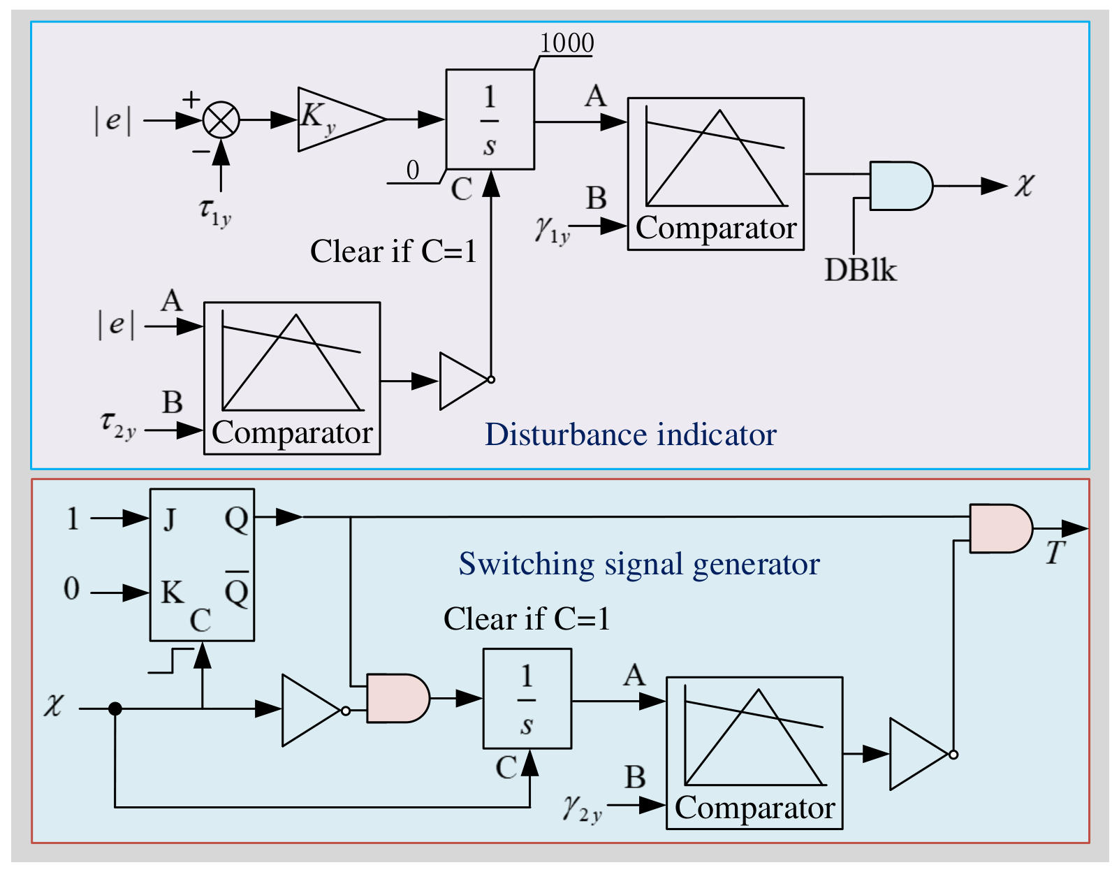
As mentioned above, the conventional PI controller is operated in a switched manner with a bang–bang funnel controller in each control loop based on a hybrid switching strategy. The switching logic is designed to ensure that the control input of the inner current control loop can be provided by the conventional PI controller when the tracking error is small, and can be provided by the bang–bang funnel controller when the tracking error is large. As shown in Figure 5, the switching logic consists of two parts, i.e., a disturbance indicator and a switching signal generator.
Let e be the tracking error of the current, τ 1 y be the threshold for | e | , and τ 2 y be another threshold value. If | e | is greater than τ 1 y , the integrator in the disturbance indicator begins to integrate, and the integrator is reset if | e | is smaller than τ 2 y . With this configuration, the continuous deviation of the current tracking error is identified. The output of the integrator is then compared with a threshold value γ 1 y , and the output of the comparator undertakes an AND operation with the deblock signal DBLK, and generates the disturbance indicator signal χ . If χ = 1 , then a continuous deviation of the current is identified; otherwise, if χ = 0 , then the current tracking error is regarded as small.
χ is then used as the triggering signal for a JK flip-flop, and the output of the JK flip-flop undertakes an AND operation with the complement of χ , output of which is integrated to generate signal A in the switching signal generator. The integrator is reset when χ = 1 . A is then compared with a threshold value γ 2 y , and the output of the comparator undertakes a NOT operation and the output undertakes an AND operation with the output of the JK flip-flop. The final output T is the switching signal for the parallel control loops.
Based on the output of the switching signal generator, the bang–bang funnel controller is activated when T = 1 , and the conventional PI controller is activated when T = 0 . The final control signals generated by the switched controller can be written as
v dr = T dr v dr b + ( 1 T dr ) v dr c v qr = T qr v qr b + ( 1 T qr ) v qr c v dg = T dg v dg b + ( 1 T dg ) v dg c v qg = T qg v qg b + ( 1 T qg ) v qg c
where T dr , T qr , T dg , and T qg are the switching signals for the inner current control loops of MSC and GSC, respectively, and v dr c , v qr c , v dg c , and v qg c are the control signals generated by the conventional PI controllers for the inner current control loops of MSC and GSC, respectively.
With this switching strategy, the bang–bang funnel controller can be activated to drive the tracking error towards the funnel boundaries when a large tracking error is detected, and the conventional PI controller can be activated to provide fine-tuning control action when the tracking error is small. The parameters of the switching logic, i.e., τ 1 y , τ 2 y , γ 1 y , and γ 2 y , are tuned by time-domain simulations to ensure the stability of the closed-loop system, and to achieve a good trade-off between the transient performance and the robustness of the closed-loop system.
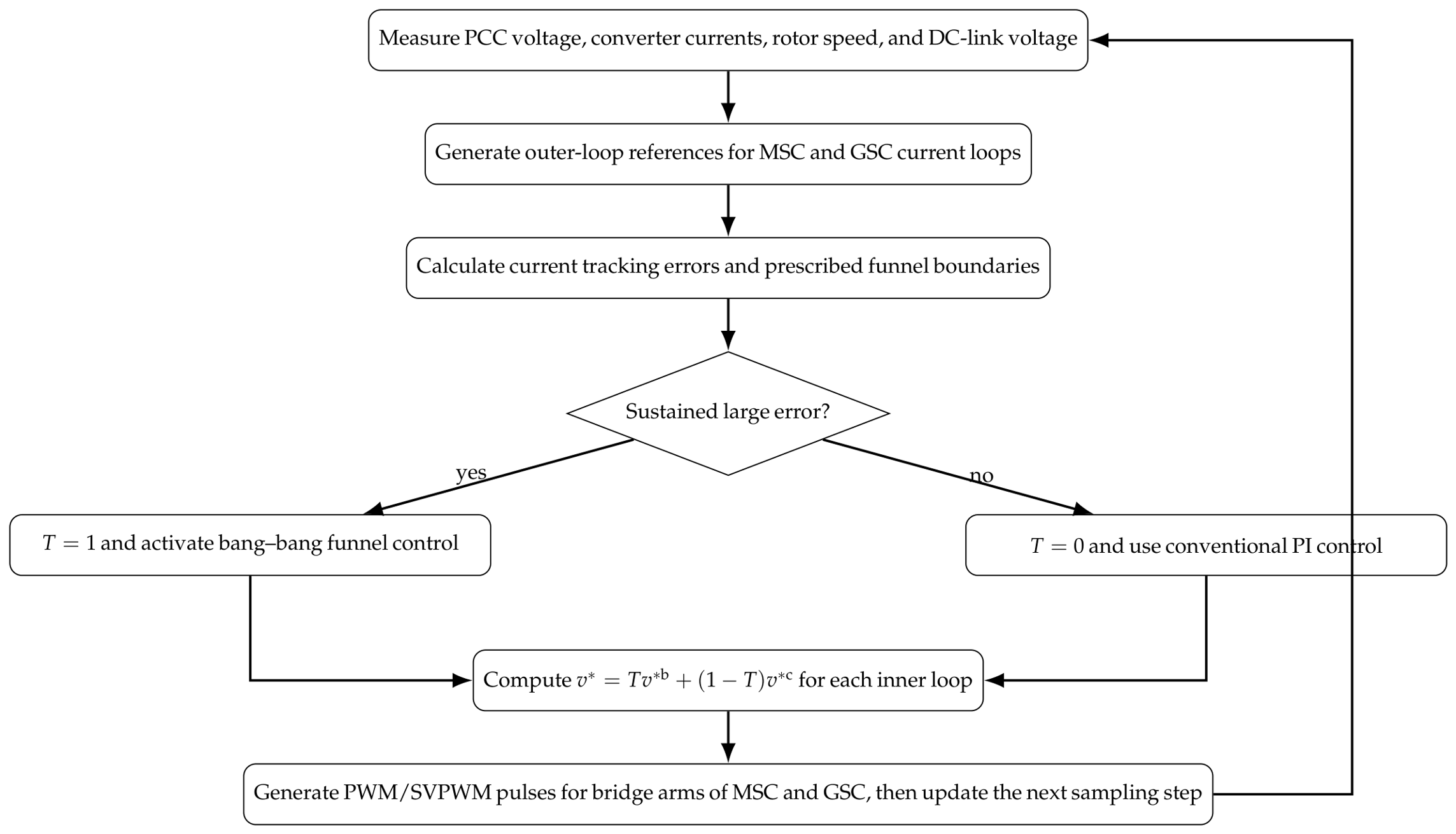
Figure 6 summarizes the main implementation steps of the proposed approach. At every sampling instant, the controller measures the electrical states, computes the outer-loop current references and inner-loop tracking errors, determines whether the error has exceeded the disturbance thresholds for a sustained time, and then selects either the high-authority bang–bang funnel action or the nominal PI action before generating the converter voltage references.

3.4. Stability of the Closed-Loop System

In the following, we will take the d-axis rotor current control loop of the MSC as an example to illustrate the stability of the closed-loop system under the proposed switching control strategy. The stability analysis can be similarly applied to the other inner current control loops of both GSC and MSC.
(1) Problem Formulation and Error Dynamics
Consider the d-axis current inner loop of the MSC. Its dynamics can be described by
d i dr d t = ω n L s L s L r L m 2 v dr R r i dr s ω L m 2 L s L r L s i qr s L m L s v ds f dr ( x ) + b dr v dr
where b dr = ω n L s L s L r L m 2 > 0 and x denotes the system state vector. Define the tracking error e dr = i dr i dr , where i dr is a bounded reference current generated by the outer loop. The error dynamics are then
d e dr d t = f dr ( x ) d i dr d t + b dr v dr
The control input v dr is given by the hybrid switching strategy:
v dr ( t ) = T dr ( t ) v dr b ( t ) + ( 1 T dr ( t ) ) v dr c ( t )
where T dr ( t ) { 0 , 1 } is the switching signal (generated by the logic in Figure 5 of the original paper), v dr c is the PI control output, and v dr b is the three-valued bang–bang control output.
(2) Finite Switching Property of the Hybrid Logic
Lemma 1 (Finite number of switches).
With the switching logic depicted in Figure 5 of the original paper, the switching signal T dr ( t ) changes only finitely many times on any finite time interval; consequently, Zeno behavior (infinitely many switches) does not occur.
Proof. 
The switching logic in Figure 5 consists of two comparators and a JK flip-flop. The first comparator checks whether | i dr e | exceeds a threshold τ 1 y . When | i dr e | > τ 1 y , an integrator starts accumulating; once its output surpasses γ 1 y , the disturbance indicator χ is set to 1. The integrator is cleared when χ = 1 or when | i dr e | < τ 2 y . Since the integrator output is continuous, χ can have only finitely many rising and falling edges on any compact time interval. The JK flip-flop toggles its output only when χ changes from 1 to 0; therefore, T dr ( t ) experiences only finitely many discontinuities on a compact interval. □
(3) Error Boundedness Under Bang–Bang Funnel Control
Lemma 2 (Error confinement by bang–bang control).
When the switching signal T dr ( t ) = 1 (bang–bang controller active), if the error i dr e ( t ) reaches the upper boundary ρ i dr e + ( t ) , the logic variable q i dr e becomes + 1 , and the control input v dr b takes the value v dr 0 + Δ v dr (with Δ v dr < 0 ). Because b dr > 0 , this negative control increment reduces i ˙ dr e , pulling the error back inside the funnel. Analogously, when the error hits the lower boundary, a positive control increment increases i ˙ dr e , restoring the error to the interior. Consequently, under the bang–bang controller, the error can always be driven into the prescribed funnel boundaries.
(4) Main Closed-Loop Stability Theorem
Assume the following conditions hold:
1.
The outer-loop reference signals i dr , i qr , i dg , i qg are bounded and piecewise continuous.
2.
The PI controller parameters are such that, under fault-free conditions and for small tracking errors, the closed-loop system is input-to-state stable.
3.
The bang–bang funnel controller parameters satisfy
Δ v dr + > sup t f dr ( x ) i ˙ dr + b dr v dr 0 ,
i.e., the available control energy is sufficient to dominate the system uncertainties and disturbances.
Theorem 1 (Closed-loop stability).
Under Assumption 1–3, the closed-loop system of the doubly-fed pumped storage unit during and after an AC grid fault is bounded-input, bounded-state stable. Moreover, all current tracking errors converge to a neighbourhood of the origin; for constant references, the convergence is asymptotic to zero.
Proof. 
The proof is divided into three phases corresponding to the fault evolution.
Phase 1: Fault inception (large error activates bang–bang control). Suppose a fault occurs at time t = t f , causing a sudden increase in the current tracking error such that | e dr | exceeds τ 1 y . According to the switching logic in Figure 5, after a finite time (the time needed for the integrator output to reach γ 1 y ), the disturbance indicator χ becomes 1, which toggles the JK flip-flop and sets T dr = 1 ; thus, the bang–bang controller is activated. By Lemma 2, under bang–bang control, the error will be driven into the prescribed funnel boundaries. Moreover, because Δ v dr ± are sufficiently large (Assumption 3), the error is driven back inside the funnel at the fastest admissible rate.
Phase 2: Error reduction and switch-back to PI control. When | i dr e | decreases below τ 2 y (with τ 2 y < τ 1 y ), the integrator is reset, χ becomes 0, and the JK flip-flop output T dr returns to 0 (if it was 1) or stays 0. Hence, control authority is handed back to the PI controller since, at this moment, the error is small, and the PI controller guarantees local asymptotic stability.
Phase 3: Post-fault recovery. Fault clearance may induce another transient error, but the switching logic repeats Phases 1 and 2. Because the fault duration is finite (e.g., 0.2 s or 0.1 s in the simulations) and the bang–bang controller is activated only when the error exceeds the threshold, the total number of switches is finite (Lemma 1). Eventually, as the grid voltage returns to normal and the system approaches a steady state, the error enters the region of attraction of the PI controller and asymptotically converges to zero. □
Energy function argumentation. Consider the following composite energy function:
V ( t ) = 1 2 x { i dr e , i qr e , i dg e , i qg e } x 2
During the bang–bang control phase, the error is confined within the funnel and the control input is bounded; by a suitable choice of Δ v ± , we can achieve V ˙ ( t ) 0 . During the PI control phase, the linearized system satisfies V ˙ ( t ) α V ( t ) locally. At switching instants, V ( t ) may have jumps, but the switching logic (which allows switching back to PI only when the error is small) guarantees that the jumps are bounded and the sequence V ( t k ) (where t k are the switching times) is decreasing. Therefore, the overall system is stable. Thus, all states of the closed-loop system remain uniformly bounded, and the current tracking errors converge asymptotically to zero. This ensures the fault ride-through capability of the doubly-fed pumped storage unit under AC grid faults.

3.5. Parameter Tuning of the Controllers

Since the switched controller consists of a conventional PI controller and a bang–bang funnel controller, the parameters of both controllers need to be tuned to ensure the stability of the closed-loop system. The parameters of the conventional PI controller are tuned based on the linearized system model, and the parameters of the bang–bang funnel controller and the switching logic are tuned by time-domain simulations. The tuning process is iterative. The tuning of the PI controllers is trivial and is not described here. The tuning of the bang–bang funnel controllers and the switching logic is described as follows:
Step 1 
The parameters of the bang–bang funnel controllers are tuned by time-domain simulations to ensure that the tracking error can be driven towards the funnel boundaries in a finite time, and can be confined within the funnel boundaries after a finite time. Based on our experience, the funnel boundary parameters, such as ρ i dr e + , ρ i dr e , ρ i qr e + , ρ i qr e , ρ i dg e + , ρ i dg e , ρ i qg e + , and ρ i qg e , are set to be the desired error band of the corresponding currents, in which the PI controllers are able offer a satisfactory control performance. The suggested values are 0.05 p.u. for all currents in this study. The bang–bang control parameters, such as Δ v dr + , Δ v dr , Δ v qr + , Δ v qr , Δ v dg + , Δ v dg , Δ v qg + , and Δ v qg are tuned based on (26) to ensure that the tracking error can be driven towards the funnel boundaries in a finite time.
Step 2 
The parameters of the switching logic are tuned by time-domain simulations to ensure that the switching signal can correctly identify the large tracking error and activate the bang–bang funnel controller, and can correctly identify the small tracking error and activate the conventional PI controller. Among the four parameters of the switching logic, γ 1 y should be set carefully to ensure that the disturbance indicator can correctly identify the large tracking error, and γ 2 y should be set carefully to ensure that the switching signal can correctly identify the small tracking error. Based on our experience, γ 1 y should be set to be around 1/4 of the rated period of the system, and γ 2 y should be set to be around 1/2 of the rated period of the system.
Step 3 
The parameters of both the bang–bang funnel controllers and the switching logic are further fine-tuned by time-domain simulations to achieve a good trade-off between the transient performance and the robustness of the closed-loop system.
The parameters of the bang–bang funnel controllers and the switching logic are robust to the system parameters, and therefore, the tuned parameters can be applied to different operating conditions and different system parameters without further tuning.

4. Simulation Verifications

The performance of the proposed switching control strategy is verified by time-domain simulations in MATLAB/Simulink. All simulations were implemented in MATLAB/Simulink R2024a on Windows 10. The parameters of the pumped storage unit are given in Table 2. The simulation step size is set to be 0.119 ms, which is 1/25 of the switching period of the converters. The system is simulated under two different scenarios, i.e., the forced excitation performance in the generating mode in terms of three-phase-to-ground faults on the AC power grid, and the forced excitation performance in the pumping mode in terms of three-phase-to-ground faults on the AC power grid.
The parameters of the conventional PI controllers are shown in Table 3, and the parameters of the bang–bang funnel controllers and the hybrid switching logic are shown in Table 4.

4.1. Forced Excitation Performance in Pumping Mode in Terms of Three-Phase-to-Ground Faults on AC Power Grid

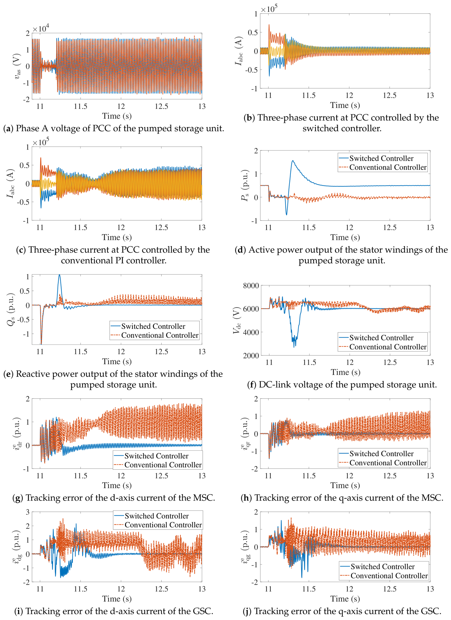
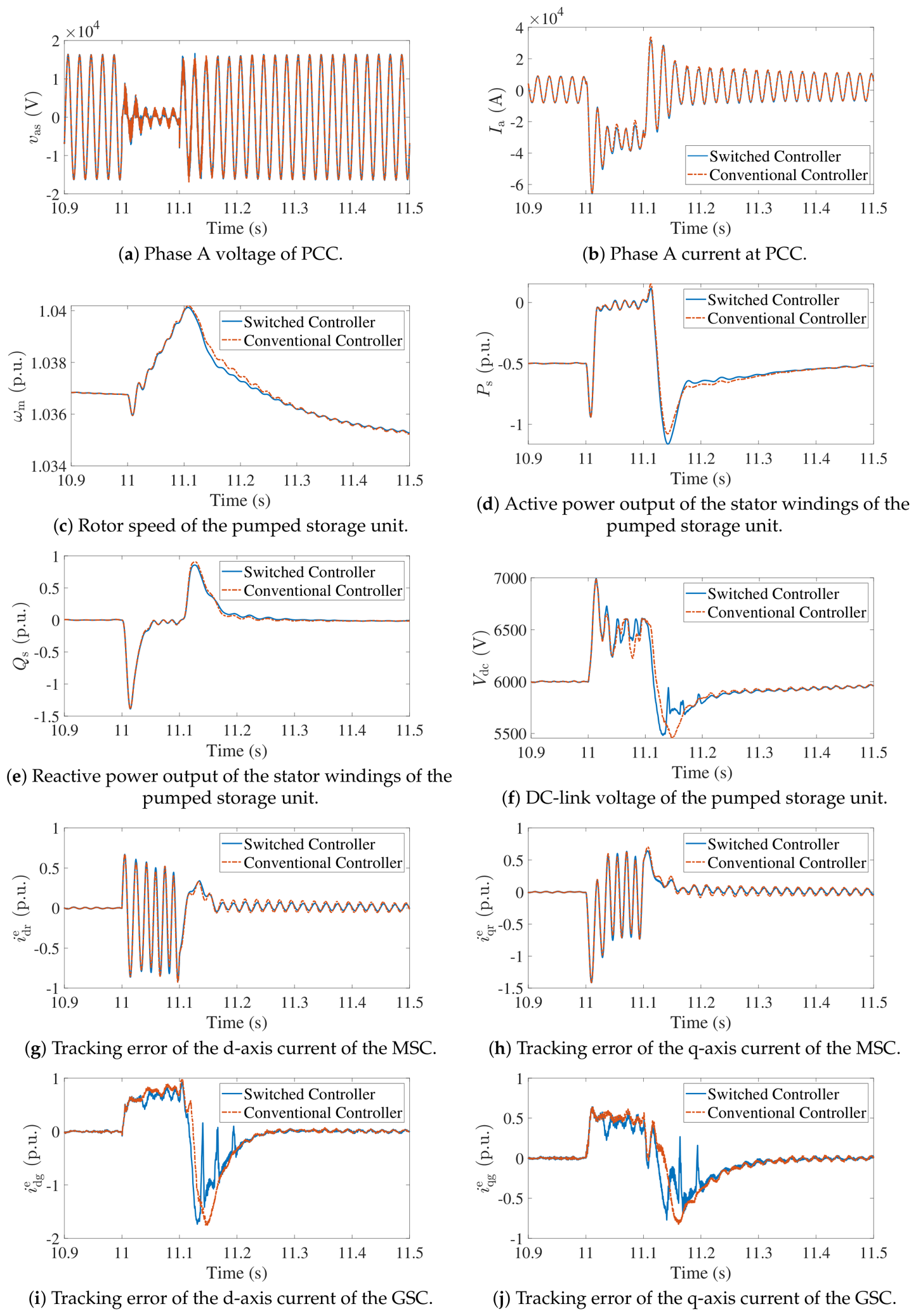
In the first scenario, the pumped storage unit is operated in pumping mode, and a three-phase-to-ground fault is simulated by a 1 p.u. voltage sag on the AC power grid at 11 s, and the fault is cleared at 11.2 s. The proposed switched controller is compared with the conventional PI controller in terms of the transient performance of the system under the fault. The simulation results are shown in Figure 7 and Figure 8. The following observations can be found in the results.
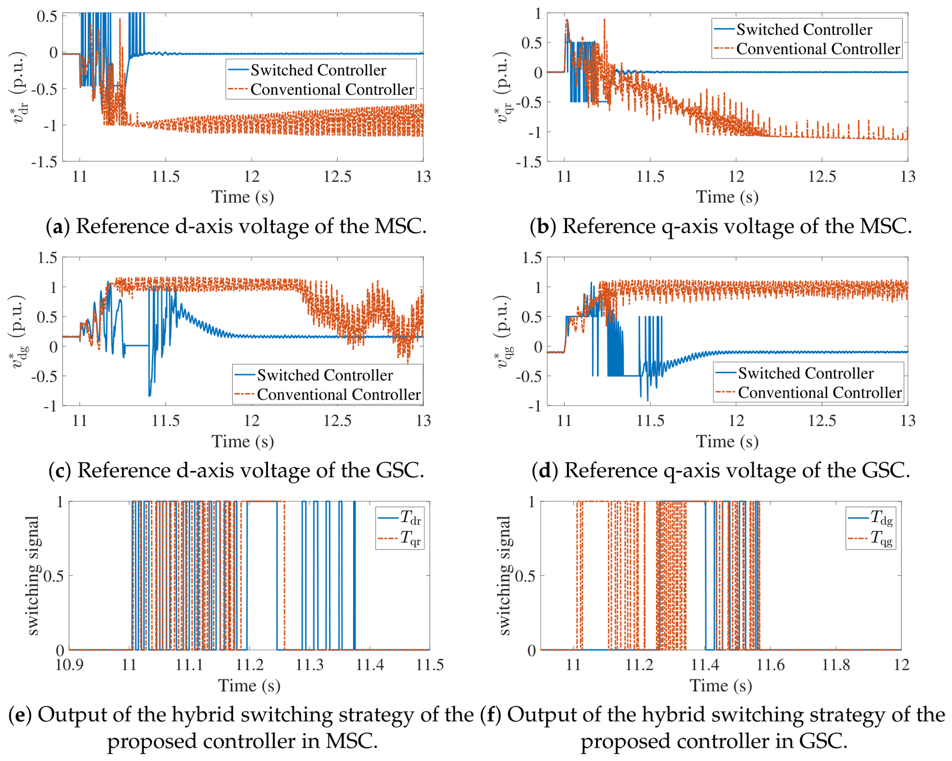
Firstly, the variable-speed pumped storage unit becomes unstable under the control of the conventional PI controller, as depicted by the three-phase current at the PCC in Figure 7a. By contrast, the proposed switched controller is able to maintain the stability of the system under the fault, and the three-phase current at the PCC is well regulated, as depicted in Figure 7b. The active power output of the stator windings of the pumped storage unit under the proposed switched controller is also well regulated, while the active power output under the conventional PI controller becomes unstable, as depicted in Figure 7d. The reactive power output of the stator windings of the pumped storage unit under the proposed switched controller is also well regulated, while the reactive power output under the conventional PI controller shows continuous oscillation after the fault is cleared, as depicted in Figure 7e. The oscillation of reactive power meets the oscillation in the PCC bus voltage, as shown in Figure 7a. The DC-link voltage of the pumped storage unit under the proposed switched controller is well regulated, while the DC-link voltage under the conventional PI controller shows continuous oscillation after the fault is cleared, as depicted in Figure 7f. The unstable dynamics of the conventional PI controller can also be found in the tracking error of the d-axis and q-axis currents of the MSC, as well as the tracking error of the d-axis and q-axis currents of the GSC, as depicted in Figure 7g–j.
Table 5 shows a quantitative comparison of the dynamics of the stator current, active power output, and DC-link voltage. As can be observed, the overshoot of the Phase A stator current and DC-link voltage after fault clearance is smaller under the proposed switched controller. The nadir value of the stator active power during the fault under the switched controller is −0.76272 p.u., which means that the pumped unit reverses its active power output during the fault. By contrast, the nadir value of the stator active power during the fault under the conventional PI controller is −0.26115 p.u., and the system becomes unstable due to the insufficient energy dissipation during the fault. The switched controller also presents better performance in terms of the settling time of the active power and DC-link voltage after the fault clearance, which is due to the fact that the switched controller can provide a stronger control action to drive the system back to the steady state after the fault clearance.
Secondly, significant differences can be found in the reference voltage generated by the proposed switched controller and the conventional PI controller. It can be seen that the bang–bang funnel controllers are triggered on both the MSC and GSC side after the voltage sag occurs, and bang–bang control signals are generated to drive the tracking error towards the funnel boundaries, as depicted in Figure 8a,f. The reference voltage generated by the proposed switched controller shows a significant deviation from the reference voltage generated by the conventional PI controller after the fault occurs, as depicted in Figure 8a–d. The significant deviation of the reference voltage under the proposed switched controller is due to the activation of the bang–bang funnel controllers, which provide strong control action to drive the tracking error towards the funnel boundaries when a large tracking error is detected. Through the employment of the bang–bang control inputs, the maximum control effort of the MSC and GSC is fully utilized to stabilize the system.
Thirdly, it can be observed that the bang–bang controllers are activated multiple times on both MSC and GSC, but zero behavior does not occur, which verifies the proper function of the designed hybrid switching logic. The switching logic is designed to ensure that the bang–bang funnel controller can be activated when a large tracking error is detected, and can be deactivated when the tracking error is reduced to a small value, which helps to maintain the stability of the closed-loop system under different operating conditions.

4.2. Forced Excitation Performance in Generating Mode in Terms of Three-Phase-to-Ground Fault on AC Power Grid

In the second scenario, the pumped storage unit is operated in generating mode, and a three-phase-to-ground fault is simulated by a 1 p.u. voltage sag on the AC power grid at 11 s, and the fault is cleared at 11.1 s. The proposed switched controller is compared with the conventional PI controller in terms of the transient performance of the system under the fault.
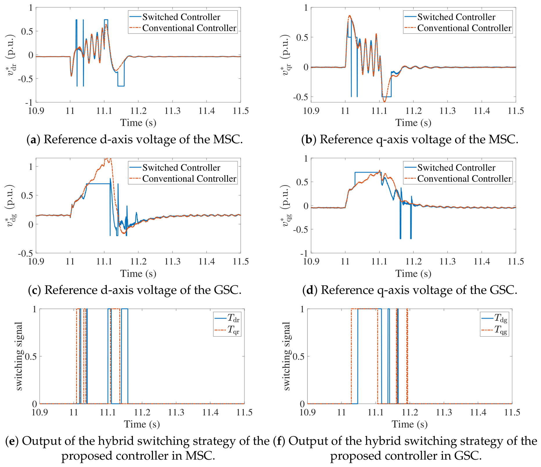
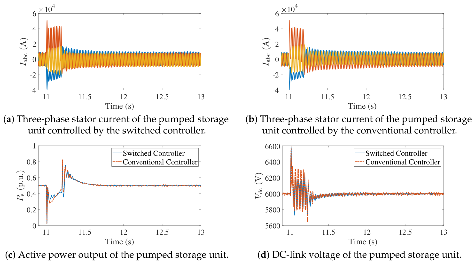
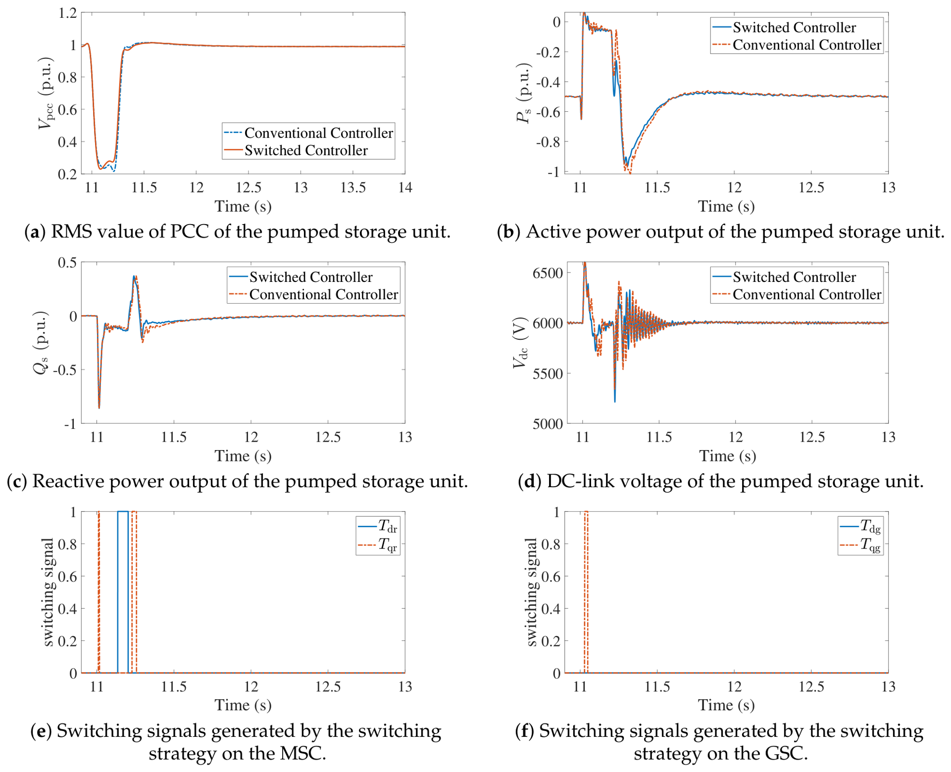
The simulation results are shown in Figure 9 and Figure 10. As demonstrated in Figure 9, the proposed switched controller exhibits significantly superior performance compared to the conventional PI controller. Firstly, it can be observed that the post-fault active power shows higher overshot in the system controlled by the switched controller, as depicted in Figure 9d, and it helps to decelerate the rotor of the generator, as shown in Figure 9c. Secondly, the DC-link voltage of the system controlled by the switched controller also shows faster recovery after the fault is cleared, as depicted in Figure 9f. The faster recovery of the DC-link voltage under the proposed switched controller is due to the activation of the bang–bang funnel controllers, which provide a strong control action to drive the tracking error towards the funnel boundaries when a large tracking error is detected. The dynamics of the switching logic on both the MSC and GSC can be observed in Figure 10e,f, where the bang–bang funnel controllers are triggered on both the MSC and GSC side after the voltage sag occurs, and bang–bang control signals are generated to drive the tracking error towards the funnel boundaries.
Table 6 shows a quantitative comparison of the dynamics of the stator current, active power output, and DC-link voltage. It shows that the overshot of stator current, active power, and DC-link voltage are smaller under the proposed switched controller. The nadir value of the DC-link voltage during the fault is higher under the proposed switched controller, which means that the DC-link voltage is better regulated during the fault. Two controllers show similar performance in terms of the settling time of the active power and DC-link voltage after the fault clearance, which is due to the fact that the PI control loops are switched on during the post-fault recovery state, and the performance of the PI controllers in terms of the settling time is similar.
Moreover, it can be found that the switching logic and the bang–bang funnel controllers operate in a coordinated manner and zero behavior does not occur in this case as well. Compared to the first case, this case is a less severe case, and thus the proposed switched controller is able to adaptive to various large-disturbance conditions, which verifies the robustness of the proposed switched controller under different operating conditions.

4.3. Fault Ride-Through Performance in Terms of Asymmetrical Fault on AC Power Grid

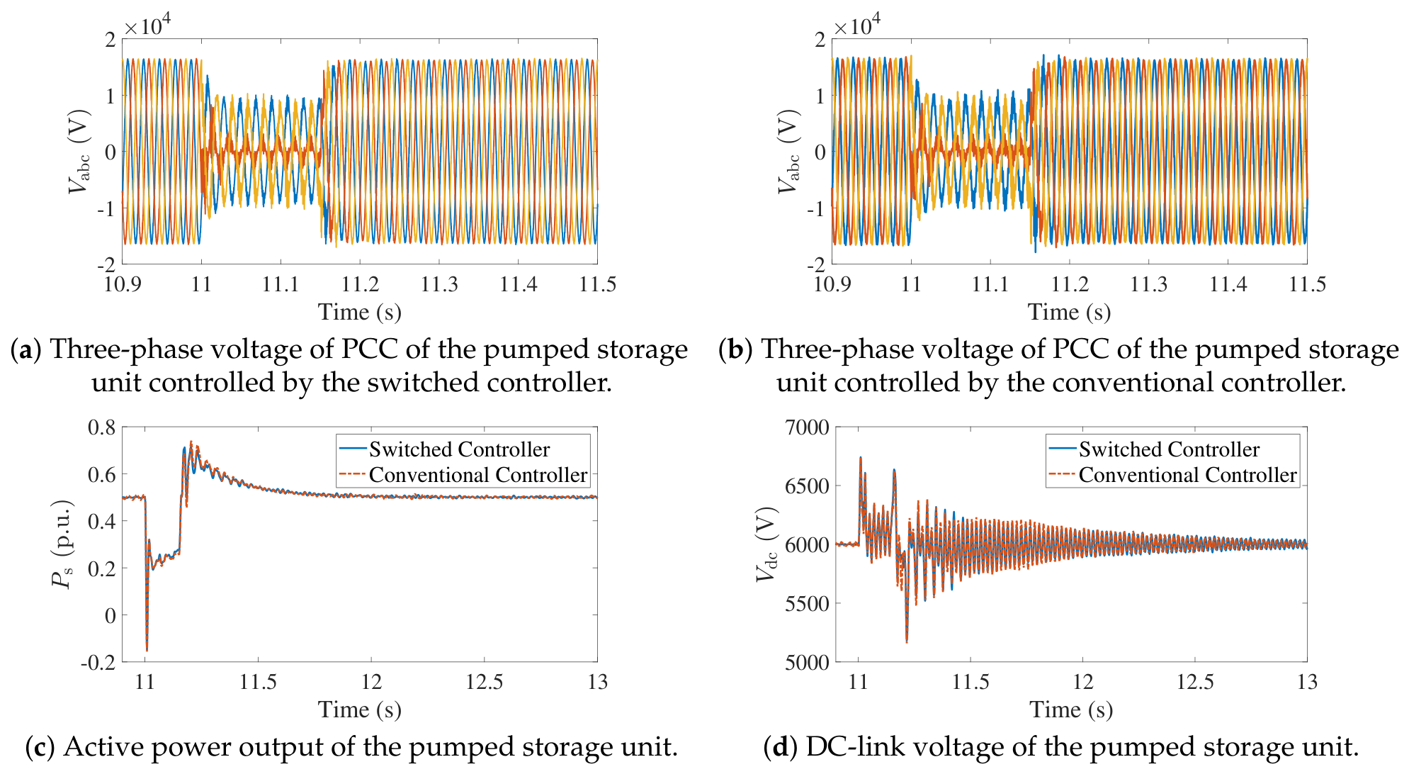
In the third scenario, the pumped storage unit is operated in pumping mode, and three kinds of asymmetrical fault, namely, single-phase-to-ground fault, two-phase-to-ground fault, and phase-to-phase fault are considered, respectively. In the first place, a single-phase-to-ground fault is simulated by a 1 p.u. voltage sag on Phase A of the AC power grid at 11 s, and the fault is cleared at 11.2 s. The simulation results are shown in Figure 11, and the switched controller shows similar performance to the conventional controller, as can been seen from the three-phase stator currents and active power of stator windings, as well as the DC-link voltages. In the second scenario, a two-phase-to-ground fault is applied in Phase A and Phase B of the PCC, and the fault duration is 0.2 s at 11 s.The simulation results are shown in Figure 12, and the proposed switched controller shows similar performance to the conventional controller, as can be seen from the three-phase voltage of PCC and active power of stator windings, as well as the DC-link voltages. Similar dynamic performances can also be obtained in the case of phase-to-phase faults, and the results are not shown here for brevity. The similar performance of the proposed switched controller and the conventional PI controller under asymmetrical faults is due to the fact that the asymmetrical faults are less severe than the symmetrical faults, and thus both controllers are able to maintain the stability of the system under asymmetrical faults. The results also verify that the proposed switched controller can adapt to various large-disturbance conditions, which further confirms the robustness of the proposed switched controller under different operating conditions.

4.4. Adaptability Under Weak Grid Conditions

In order to verify the adaptability of the proposed switched controller under weak grid conditions, the AC grid strength is reduced, and the short circuit ratio (SCR) of the AC power grid is set to be 2.5 by increasing the grid impedance. A three-phase-to-ground fault is simulated by a 1 p.u. voltage sag on the AC power grid at 11 s, and the fault is cleared at 11.2 s. The simulation results are shown in Figure 13 and Table 7. It can be observed that the proposed switched controller shows better performance than the conventional PI controller in terms of the overshoot of the PCC voltage, active power output, and DC-link voltage after the fault clearance. The nadir value of the PCC voltage during the fault under the switched controller is higher than that under the conventional PI controller, which means that the PCC voltage is better regulated during the fault under the proposed switched controller. Both the bang–bang funnel controllers on MSC and GSC are triggered multiple times, which provides a strong control action to drive the tracking error towards the funnel boundaries when a large tracking error is detected, and thus helps to maintain the stability of the system under weak grid conditions. The settling time of the active power and DC-link voltage after the fault clearance under the proposed switched controller is also smaller than that under the conventional PI controller, which means that the system can recover faster after the fault clearance under the proposed switched controller. The results verify that the proposed switched controller can adapt to various large-disturbance conditions, which further confirms the robustness of the proposed switched controller under different operating conditions.

5. Discussion

The comparative simulations reveal a clear contrast in performance between the two controllers. In pumping mode (Figure 7), the conventional PI controller fails to maintain system stability under the 1 p.u. voltage sag: the three-phase current at the PCC diverges, and both the active/reactive power outputs and the DC-link voltage exhibit sustained oscillations after fault clearance. By contrast, the proposed switched controller maintains stability throughout, with well-regulated three-phase currents, smooth power recovery, and a bounded DC-link voltage. The d/q current tracking errors on both the MSC and GSC channels are effectively confined by the funnel boundaries, and the bang–bang controllers are triggered on multiple occasions without exhibiting zero behavior, which confirms the correct operation of the hybrid switching logic. In generating mode (Figure 9), which represents a comparatively less severe disturbance, both controllers preserve stability, yet the switched controller demonstrates notably superior dynamic performance: it produces a higher post-fault active power overshoot that assists rotor deceleration, achieves faster DC-link voltage recovery, and eliminates the residual current oscillations observed under PI control. The switching logic and bang–bang funnel controllers again operate in a coordinated manner without Zeno behavior, corroborating the robustness of the proposed strategy across different operating conditions.
Mechanistically, the superior performance originates from the ability of the switched controller to deploy the maximum available control authority of the MSC and GSC precisely when tracking errors approach the prescribed funnel boundaries. A fixed-gain PI controller cannot exploit this authority because its output is inherently proportional to the error and integral state, which become saturated or slow to respond under deep voltage sags. The bang–bang action, activated by the hybrid switching logic, drives the rotor and grid-side currents back within the funnel boundaries at the fastest admissible rate, thereby limiting flux linkage excursions, suppressing converter–filter coupling effects, and preserving DC-link energy balance. Once the disturbance subsides and errors fall below the switching thresholds, the PI controller resumes regulation, ensuring smooth steady-state behavior and avoiding unnecessary chattering. From a practical standpoint, the results indicate that the proposed strategy can be applied to both pumping and generating modes without retuning the controller parameters, which simplifies commissioning and reduces operational risk. Nonetheless, several aspects warrant attention in future work: the sensitivity of the funnel boundary parameters to machine and grid parameter variations, the coordination of the bang–bang ride-through logic with outer-loop frequency and voltage support functions, and validation under asymmetrical fault conditions and partial voltage sags via hardware-in-the-loop experiments and field tests.
Compared with the literature summarized in Table 1, the proposed method provides a different trade-off. Passive crowbar protection can limit current but sacrifices converter controllability during the fault. Dynamic flux linkage and reactive current optimization methods improve selected FRT indices, but they still rely on model-based parameter scheduling or online optimization. Virtual inductance and DC-link-boosting methods improve the converter voltage margin, but require additional coordination between the virtual impedance and DC-link regulation. The proposed switched bang–bang funnel controller instead keeps the conventional PI loops during normal operation and activates the maximum admissible converter control action only when the current errors approach the prescribed funnel boundaries. This explains why the method can avoid instability in pumping mode and improve DC-link voltage recovery in generating and weak-grid cases while preserving nominal PI behavior after the fault is cleared.
In terms of other nonlinear fault ride-through control strategies, such as sliding mode control and model predictive control, the proposed switched bang–bang funnel control strategy has the advantage of simplicity in implementation and tuning. Sliding mode control can achieve robust performance under parameter uncertainties and external disturbances, but it may suffer from chattering issues that can lead to increased wear and tear on the system components. Model predictive control can optimize the control actions over a prediction horizon, but it requires accurate system models and can be computationally intensive, which may not be suitable for real-time applications. The proposed switched bang–bang funnel control strategy, on the other hand, leverages the maximum available control authority of the converters when needed while maintaining a simple structure that is easier to implement and tune in practice.
Under steady-state conditions, the proposed switched controller behaves in the same manner as the conventional PI controller, since the tracking errors are well within the funnel boundaries and the bang–bang controllers are not activated. This means that the proposed switched controller can achieve similar switching frequency-related metrics as the conventional PI controller under normal operating conditions, such as harmonic distortion and converter switching losses, as well as converter efficiency. During transient conditions, the bang–bang funnel controllers may be activated, but the switching frequency-related performance metrics, such as switching losses and harmonic distortion, are not significantly affected by the proposed switched controller compared to the conventional PI controller, since the bang–bang control signals also go through PWM/SVPWM modulation. The carrier frequencies for the PWM generator for the GSC and that of the SVPWM for the MSC under the switched controller and conventional PI controller are the same. Therefore, the switching frequency-related performance metrics under the proposed switched controller and the conventional PI controller are similar.
The present work also has several shortcomings. First, the validation is simulation-based, and hardware-in-the-loop or field tests are still required before engineering deployment. Second, the asymmetrical-fault cases are evaluated mainly from a dynamic-response perspective, while detailed negative-sequence current constraints and thermal stress on converter devices require further investigation. Finally, the coordination between the proposed inner-loop FRT logic and plant-level voltage/frequency support functions remains an important topic for future work.

6. Conclusions

This paper proposed a switched bang–bang funnel control strategy for the MSC and GSC of a doubly-fed variable-speed pumped storage unit to improve fault ride-through capability under severe AC grid faults. The method combines conventional PI regulation with three-value bang–bang funnel controllers for the MSC current loops, two-value bang–bang funnel controllers for the GSC current loops, and a hybrid switching logic that activates the bang–bang action only when the current tracking errors approach prescribed performance boundaries.
Comparative MATLAB/Simulink simulations show that, in pumping mode under a 1 p.u. three-phase-to-ground voltage sag, the conventional PI controller becomes unstable after fault clearance, whereas the proposed switched controller maintains stable currents, active/reactive power, and DC-link voltage; the settling times of stator active power and DC-link voltage are 1.667 s and 0.48637 s, respectively. In the generating mode, both controllers remain stable, but the proposed controller reduces the Phase A current overshoot from 33,782 A to 31,821 A, active power overshoot from 0.15399 p.u. to 0.11662 p.u., and DC-link voltage recovery time from 0.04875 s to 0.02958 s. Under the weak-grid case with SCR = 2.5, it also shortens active power and DC-link voltage settling times from 0.869 s to 0.793 s and from 0.1284 s to 0.1093 s, respectively. These results indicate that the proposed controller can exploit the converters’ maximum available control authority during large disturbances while preserving nominal PI behavior after recovery, thereby improving FRT stability and simplifying parameter commissioning across operating modes. Future work will include hardware-in-the-loop and field validation, sensitivity analysis under machine and grid parameter uncertainties, and coordination with plant-level voltage and frequency support functions.

Author Contributions

Conceptualization, Y.P.; methodology, R.H. and L.X.; software, F.H. and C.W.; validation, W.Y. and H.L.; formal analysis, Y.P.; investigation, R.H.; resources, Y.L.; writing—original draft preparation, R.H.; writing—review and editing, Y.L.; supervision, Y.L.; project administration, Y.L.; funding acquisition, Y.L. All authors have read and agreed to the published version of the manuscript.

Funding

This research was funded by Key Technology Project of China Southern Power Grid Co., Ltd., under grant number STKJXM20210102.

Institutional Review Board Statement

Not applicable.

Informed Consent Statement

Not applicable.

Data Availability Statement

The data presented in this study are available on request from the corresponding author due to the fact that the data are being used in ongoing engineering projects.

Acknowledgments

The authors have reviewed and edited the output and take full responsibility for the content of this publication.

Conflicts of Interest

Authors Rufei He, Yumin Peng, Fanqi Huang, Chao Wen and Hanyuan Li were employed by China Southern Power Grid Power Generation Company Ltd., Energy Storage Research Institute, Guangzhou, China; author Lei Xie was employed by Shenzhen Hopewind Electric Co., Ltd., Shenzhen, China; author Wenbin Yan was employed by China Southern Power Grid Power Generation Company Ltd., Overhaul and Testing Branch, Guangzhou, China. The remaining author declares that the research was conducted in the absence of any commercial or financial relationships that could be construed as a potential conflict of interest. The authors declare that this study received funding from China Southern Power Grid Co., Ltd. The funder was not involved in the study design, collection, analysis, interpretation of data, the writing of this article or the decision to submit it for publication.

Abbreviations

The following abbreviations are used in this manuscript:
MSCmachine-side converter
GSCgrid-side converter
FRTfault ride-through
PLLphase-locked loop
PIproportional and integral
NPCneutral-point-clamped converter
PCCpoint of common coupling

Nomenclature

v ds d-axis component of the PCC voltage in V or p.u.
R s resistance of the stator winding in Ω or p.u.
i ds d-axis current flowing into the stator windings in A or p.u.
p d / d t the derivative operator with respect to time
ψ ds d-axis stator flux of the pumped storage unit in Wb or p.u.
ω frequency measured by the PLL in rad/s or p.u.
ψ qs q-axis stator flux of the pumped storage unit in Wb or p.u.
v qs q-axis component of the PCC voltage in V or p.u.
i qs q-axis current flowing into the stator windings in A or p.u.
v dr d-axis output voltage of the MSC that refers to the stator side in V or p.u.
R r resistance of the rotor winding referring to the stator side in Ω or p.u.
i dr d-axis current flowing into the rotor windings referring to the stator side in A or p.u.
ψ dr d-axis rotor flux of the pumped storage unit referring to the stator side in Wb or p.u.
sslip of the induction machine
v qr q-axis component of the output voltage of the MSC
that refers to the stator side in V or p.u.
i qr q-axis current flowing into the rotor windings referring to the stator side in A or p.u.
ψ qr q-axis rotor flux of the pumped storage unit referring to the stator side in Wb or p.u.
v n rated phase-to-ground voltage in Volt
i n rated current in A
ψ n rated flux in Wb
Z n rated impedance in Ω
ω n rated angular frequency in rad/s
v ¯ ds normalized d-axis component of the PCC voltage in p.u.
R ¯ s normalized resistance of the stator winding in p.u.
i ¯ ds normalized d-axis current flowing into the stator windings in p.u.
ψ ¯ ds normalized d-axis stator flux of the pumped storage unit in p.u.
ω ¯ normalized frequency measured by the PLL in p.u.
ψ ¯ qs normalized q-axis stator flux of the pumped storage unit in p.u.
v ¯ qs normalized q-axis component of the PCC voltage in p.u.
i ¯ qs normalized q-axis current flowing into the stator windings in p.u.
v ¯ dr normalized d-axis component of the output voltage of the MSC in p.u.
R ¯ r normalized resistance of the rotor winding referring to the stator side in p.u.
i ¯ dr normalized d-axis current flowing into the rotor windings in p.u.
ψ ¯ dr normalized d-axis rotor flux of the pumped storage unit in p.u.
v ¯ qr normalized q-axis component of the output voltage of the MSC in p.u.
i ¯ qr normalized q-axis current flowing into the rotor windings in p.u.
ψ ¯ qr normalized q-axis rotor flux of the pumped storage unit in p.u.
ω r rotor angular frequency in rad/s or p.u.
L ¯ s normalized stator self-inductance in p.u.
L ¯ m normalized mutual inductance in p.u.
L ¯ r normalized rotor self-inductance in p.u.
L ¯ ls normalized stator leakage inductance in p.u.
L ¯ lr normalized rotor leakage inductance in p.u.
H v equivalent inertia of the turbine and generator in seconds
T ¯ m normalized mechanical torque of the turbine in p.u.
T ¯ e normalized electromagnetic torque of the generator in p.u.
Δ ω r deviation of the rotor angular frequency in p.u.
H t inertia of the turbine in seconds
N c gear ratio of the turbine and generator
H g inertia of the generator in seconds
Dequivalent damping coefficient of the turbine and generator in p.u.
e T w damping coefficient of the turbine in p.u.
D g damping coefficient of the generator in p.u.
P ¯ s normalized active power output of the stator in p.u.
Q ¯ s normalized reactive power output of the stator in p.u.
L ¯ g normalized inductance of the grid-side filter in p.u.
v ¯ qg normalized q-axis component of the grid-side converter in p.u.
R ¯ g normalized resistance of the grid-side filter in p.u.
i ¯ qg normalized q-axis current flowing into the grid-side converter in p.u.
v ¯ dg normalized d-axis component of the grid-side converter in p.u.
i ¯ dg normalized d-axis current flowing into the grid-side converter in p.u.
P s reference for the active power output of the stator in p.u.
Q s reference for the reactive power output of the stator in p.u.
V dc reference for the DC-link voltage in p.u.
i qg reference for the q-axis current of the grid-side converter in p.u.
i dr reference for the d-axis current of the machine-side converter in p.u.
i qr reference for the q-axis current of the machine-side converter in p.u.
i dg reference for the d-axis current of the grid-side converter in p.u.
v dg c reference for the d-axis component of the grid-side converter voltage in p.u.
v qg c reference for the q-axis component of the grid-side converter voltage in p.u.
v dr c reference for the d-axis component of the machine-side converter voltage in p.u.
v qr c reference for the q-axis component of the machine-side converter voltage in p.u.
v dr PI reference for d-axis component of MSC voltage generated by PI controller in p.u.
v qr PI reference for q-axis component of MSC voltage generated by PI controller in p.u.
v dr b reference for d-axis component of MSC voltage generated by bang–bang in p.u.
controller
v qr b reference for q-axis component of MSC voltage generated by bang–bang in p.u.
controller
Δ v dr + positive-effect value of the control input of the bang–bang controller in p.u.
Δ v dr negative-effect value of the control input of the bang–bang controller in p.u.
q i dr e switching signal of the bang–bang controller for the d-axis current control
loop of the MSC
i dr e ( t ) tracking error of the d-axis current control loop of the MSC in p.u.
q i dr e old previous value of the switching signal of the bang–bang controller
for the d-axis current control loop of the MSC
ρ i dr e + ( t ) upper boundary of the funnel for the tracking error of the d-axis current
control loop of the MSC
ρ i dr e ( t ) lower boundary of the funnel for the tracking error of the d-axis current
control loop of the MSC
v ds ( t ) reference for the d-axis component of the stator voltage in p.u.
v dr 0 ( t ) steady-state reference for the d-axis component of the MSC voltage in p.u.
i qr e ( t ) tracking error of the q-axis current control loop of the MSC
q i qr e switching signal of the bang–bang controller for the q-axis current control
loop of the MSC
q i qr e old previous value of the switching signal of the bang–bang controller
for the q-axis current control loop of the MSC
ρ i qr e + ( t ) upper boundary of the funnel for the tracking error of the q-axis current
control loop of the MSC
ρ i qr e ( t ) lower boundary of the funnel for the tracking error of the q-axis current
control loop of the MSC
v qr 0 ( t ) steady-state reference for the q-axis component of the MSC voltage in p.u.
logical OR operator
logical AND operator
v dg 0 ( t ) steady-state reference for the d-axis component of the GSC voltage in p.u.
v qg 0 ( t ) steady-state reference for the q-axis component of the GSC voltage in p.u.
Δ v dg + positive-effect value of the control input of the bang–bang controller in p.u.
Δ v dg negative-effect value of the control input of the bang–bang controller
q i dg e switching signal of the bang–bang controller for the d-axis current loop
q i dg e old previous value of the switching signal of the bang–bang controller
ρ i dg e + ( t ) upper boundary of the funnel for the tracking error of the d-axis current loop
ρ i dg e ( t ) lower boundary of the funnel for the tracking error of the d-axis current loop
q i qg e switching signal of the bang–bang controller for the q-axis current loop
q i qg e old previous value of the switching signal of the bang–bang controller
ρ i qg e + ( t ) upper boundary of the funnel for the tracking error of the q-axis current loop
ρ i qg e ( t ) lower boundary of the funnel for the tracking error of the q-axis current loop
f c carrier frequency for PWM/SVPWM in Hz

References

  1. Piya, P.; Ebrahimi, M.; Karimi-Ghartemani, M.; Khajehoddin, S.A. Fault Ride-Through Capability of Voltage-Controlled Inverters. IEEE Trans. Ind. Electron. 2018, 65, 7933–7943. [Google Scholar] [CrossRef]
  2. Sun, L.; Lei, T.; Wang, J.; Kang, H.; Li, Z.; Zhou, L.; Wu, Q.; Ma, Y. Accelerated Start-Up Model for Variable-Speed Pumped Storage Units Based on Parameter Matching and Topology Optimization. CSEE J. Power Energy Syst. 2026, 1–12. [Google Scholar] [CrossRef]
  3. Joseph, A.; Desingu, K.; Semwal, R.R.; Chelliah, T.R.; Khare, D. Dynamic Performance of Pumping Mode of 250 MW Variable Speed Hydro-Generating Unit Subjected to Power and Control Circuit Faults. IEEE Trans. Energy Convers. 2018, 33, 430–441. [Google Scholar] [CrossRef]
  4. Wu, C.-C.; Lee, W.-J.; Cheng, C.-L.; Lan, H.-W. Role and Value of Pumped Storage Units in an Ancillary Services Market for Isolated Power Systems—Simulation in the Taiwan Power System. IEEE Trans. Ind. Appl. 2008, 44, 1924–1929. [Google Scholar] [CrossRef]
  5. Chen, Y.; Xu, W.; Liu, Y.; Bao, Z.; Mao, Z.; Rashad, E.M. Modeling and Transient Response Analysis of Doubly-Fed Variable Speed Pumped Storage Unit in Pumping Mode. IEEE Trans. Ind. Electron. 2023, 70, 9935–9947. [Google Scholar] [CrossRef]
  6. Zhu, D.; Wang, Z.; Ma, Y.; Hu, J.; Zou, X.; Kang, Y. Hybrid LVRT Control of Doubly-Fed Variable Speed Pumped Storage to Shorten Crowbar Operational Duration. IEEE Trans. Power Electron. 2024, 39, 14192–14203. [Google Scholar] [CrossRef]
  7. Yu, W.; Chen, W.; Li, X. Research on Low-Voltage Ride-Through of Grid-Forming Doubly-Fed Variable-Speed Pumped Storage Units. In 2025 IEEE 3rd International Power Electronics and Application Symposium (PEAS); IEEE: Piscataway, NJ, USA, 2025; pp. 1482–1487. [Google Scholar]
  8. Chen, Y.; Lu, W.; Wang, S.; Li, S.; Yan, Y. Research on Optimizing Reactive Power Support Capability of Variable-Speed Pumped Storage Units. In Proceedings of the 2025 7th International Conference on Energy Systems and Electrical Power (ICESEP), Wuhan, China, 20–22 June 2025; pp. 578–583. [Google Scholar]
  9. Li, X.; Chen, Y.; Yu, W.; Li, L.; Yao, P.; Lan, J.; Ai, J.; Chen, W. Virtual Inductance and DC Boosting Control Based Low Voltage Ride-Through Method for Doubly-Fed Variable-Speed Pumped Hydro Storage Units. IEEE Trans. Power Electron. 2026, 41, 6125–6135. [Google Scholar] [CrossRef]
  10. Chen, X.; Wang, L.; Liu, Y.; Wu, Q. Bang-Bang Funnel Control of Three-Phase Full-Bridge Inverter Under Dual-Buck Scheme. IEEE Trans. Ind. Electron. 2023, 69, 5399–5409. [Google Scholar] [CrossRef]
  11. Liu, Y.; Wu, Q.H.; Zhou, X.X.; Jiang, L. Perturbation Observer Based Multiloop Control for the DFIG-WT in Multimachine Power System. IEEE Trans. Power Syst. 2014, 29, 2905–2915. [Google Scholar] [CrossRef]
  12. Zhao, Q.; Liao, K.; Ren, Z.; Yang, J.; He, Z. Two-Level Coordinated Power Control Strategy for Multiple Variable Speed Pumped Storage Units Participating in Primary Frequency Regulation. IEEE Trans. Power Syst. 2026, 41, 747–759. [Google Scholar] [CrossRef]
  13. Chen, Y.; Xu, W.; Liu, Y.; Mao, Z.; Bao, Z.; Yao, W.; Rashad, E.M.; Hussien, M.G. Small-Signal System Frequency Stability Analysis of the Power Grid Integrated With Type-II Doubly-Fed Variable Speed Pumped Storage. IEEE Trans. Energy Convers. 2023, 38, 611–623. [Google Scholar] [CrossRef]
  14. Joseph, A.; Selvaraj, R.; Chelliah, T.R.; Sarma, S.V.A. Starting and Braking of a Large Variable Speed Hydrogenerating Unit Subjected to Converter and Sensor Faults. IEEE Trans. Ind. Appl. 2018, 54, 3372–3382. [Google Scholar] [CrossRef]
  15. Desingu, K.; Selvaraj, R.; Chelliah, T.R.; Khare, D. Effective Utilization of Parallel-Connected Megawatt Three-Level Back-to-Back Power Converters in Variable Speed Pumped Storage Units. IEEE Trans. Ind. Appl. 2019, 55, 6414–6426. [Google Scholar] [CrossRef]
  16. Krause, P.C.; Wasynczuk, O.; Sudhoff, S.D. Analysis of Electric Machinery and Drive Systems, 2nd ed.; Wiley-IEEE Press: New York, NY, USA, 2013. [Google Scholar]
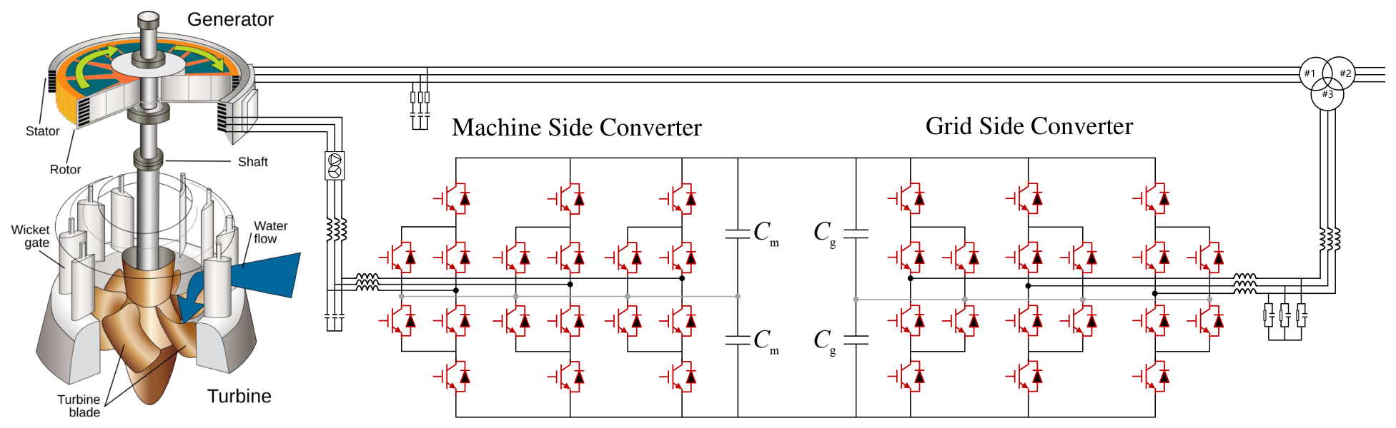
Figure 1. Layout of a doubly-fed pumped storage unit.
Electronics 15 02356 g001
Figure 2. Schematic of the control system for the back-to-back converters of the pumped storage unit.
Electronics 15 02356 g002
Figure 3. Schematic of the conventional PI control loops for the GSC and MSC.
Electronics 15 02356 g003
Figure 4. Schematic of the bang–bang funnel controllers for the inner current control loops of both GSC and MSC.
Electronics 15 02356 g004
Figure 5. Hybrid switching logic for the inner current control loops.
Electronics 15 02356 g005
Figure 6. Flowchart of the proposed switched bang–bang funnel control approach.
Electronics 15 02356 g006
Figure 7. Comparison of the performance of the proposed switching control strategy with the conventional PI controller in pumping mode under a three-phase-to-ground fault on AC power grid.
Electronics 15 02356 g007
Figure 8. Comparison of controller signals of the proposed switching control strategy and the conventional PI controllers in pumping mode under a three-phase-to-ground fault on a AC power grid.
Electronics 15 02356 g008
Figure 9. Comparison of the performance of the proposed switching control strategy with the conventional PI controller in generating mode under a three-phase-to-ground fault on AC power grid.
Electronics 15 02356 g009
Figure 10. Comparison of controller signals of the proposed switching control strategy and the conventional PI controllers in generating mode under a three-phase-to-ground fault on AC power grid.
Electronics 15 02356 g010
Figure 11. Comparison of dynamic performance of the proposed switching control strategy and the conventional PI controllers in pumping mode under a single-phase-to-ground fault on AC power grid.
Electronics 15 02356 g011
Figure 12. Comparison of dynamic performance of the proposed switching control strategy and the conventional PI controllers in pumping mode under a double-phase-to-ground fault on AC power grid.
Electronics 15 02356 g012
Figure 13. Comparison of dynamic performance of the proposed switching control strategy and the conventional PI controllers in generating mode under a three-phase-to-ground fault on weak AC power grid with SCR = 2.5.
Electronics 15 02356 g013
Table 1. Summary of fault ride-through control strategies for doubly-fed variable-speed pumped storage units.
CategoryMethod/ReferenceAdvantageLimitation
PassiveCrowbar protection [6]Simple, reliable, protects converterLoss of controllability, absorbs reactive power, causes torque oscillations
Active: Model-basedDynamic flux linkage control [7]Fast flux decay, improves reactive responseFixed parameters limit performance
under severe faults
Reactive power optimization [8]Increases reactive support (≈10%)High computational burden
for real-time optimization
Virtual inductance + DC boosting [9]Better current suppressionLacks coordination mechanism
Active: Model-freeBang–bang control [10]Fast, robustNot yet applied;
balancing transient/steady-state
is challenging
Observer-based control [11]Adapts to changesComplex design,
extensive tuning required
Table 2. Parameters of the pumped storage unit.
Parameter DescriptionValueParameter DescriptionValue
rated capacity S n 1050 MVArated frequency f n 50 Hz
nominal L-L stator voltage20 kVnominal L-L rotor voltage60 kV
inductance of stator winding0.096 p.u.inductance of rotor winding0.176 p.u.
mutual inductance2.72 p.u.stator resistance0.001 p.u.
rotor resistance0.001 p.u.inertia constant4 s
number of pole pairs6nominal rotor speed500 rpm
filter inductance of GSC0.01 p.u.filter resistance of GSC0.001 p.u.
filter inductance of MSC0.005 p.u.filter resistance of MSC0.0005 p.u.
nominal DC-link voltage6 kVcontrollers sampling frequency10 kHz
DC bus capacitance0.1 Fmechanical damping0.001 p.u.
nominal L-L grid voltage500 kVgrid frequency50 Hz
short-circuit capacity of grid8 × 1011 VAX/R ratio of the grid9
f c for GSC600 Hz f c for MSC300 Hz
Table 3. Parameters of the conventional PI controllers.
Parameter DescriptionValueParameter DescriptionValue
PI10.12, 0.2PI22, 0.5
PI3100, 200PI40.1, 2
f c for GSC600 Hz f c for MSC300 Hz
Table 4. Parameters of the bang–bang funnel controllers and the hybrid switching logic.
Parameter DescriptionVALUEParameter DescriptionValue
ρ i dr e + 0.05 p.u. ρ i dr e −0.05 p.u.
ρ i qr e + 0.05 p.u. ρ i qr e −0.05 p.u.
Δ v dr + 0.5 p.u. Δ v dr −0.5 p.u.
Δ v qr + 0.5 p.u. Δ v qr −0.5 p.u.
ρ i dg e + 0.1 p.u. ρ i dg e −0.1 p.u.
ρ i qg e + 0.1 p.u. ρ i qg e −0.1 p.u.
Δ v dg + 0.5 p.u. Δ v dg −0.5 p.u.
Δ v qg + 0.5 p.u. Δ v qg −0.5 p.u.
τ 1 y 0.1 τ 2 y 0.01
γ 1 y 0.005 γ 2 y 0.01
Table 5. Quantitative comparison of the proposed switched controller and the conventional PI controller in pumping mode under a three-phase-to-ground fault on an AC power grid.
Index I a (Switched vs. Conventional) P s (Switched vs. Conventional) V dc (Switched vs. Conventional)
overshoot45,402/47,7221.5688/0.504157044.3/7050.9
nadir value−67,716/−66,740−0.76272/−0.261152684.2/5575.5
settling timeno applicable1.667/inf0.48637/inf
stable or notstable/unstablestable/unstablestable/unstable
Table 6. Quantitative comparison of the proposed switched controller and the conventional PI controller in generating mode under a three-phase-to-ground fault on AC power grid.
Index I a (Switched vs. Conventional) P s (Switched vs. Conventional) V dc (Switched vs. Conventional)
overshoot31,821/33,7820.11662/0.153996994.7/6989
nadir value−65,932/−65,897−1.1617/−1.07775482.1/5456.8
settling timeno applicable0.38887/0.368210.02958/0.04875
stable or notstable/stablestable/stablestable/stable
Table 7. Quantitative comparison of the proposed switched controller and the conventional PI controller in generating mode under a three-phase-to-ground fault on weak AC power grid with SCR = 2.5.
Index V pcc (Switched vs. Conventional) P s (Switched vs. Conventional) V dc (Switched vs. Conventional)
overshoot1.0123/1.0130.0608/0.06246606.3/6606.3
nadir value0.22988/0.21627−0.9634/−1.01645221.6/5337.1
settling time0.093/0.09960.793/0.8690.1093/0.1284
stable or notstable/stablestable/stablestable/stable
Disclaimer/Publisher’s Note: The statements, opinions and data contained in all publications are solely those of the individual author(s) and contributor(s) and not of MDPI and/or the editor(s). MDPI and/or the editor(s) disclaim responsibility for any injury to people or property resulting from any ideas, methods, instructions or products referred to in the content.