Article

A Human-Centric Virtual World for Nuclear Power Plants: A Methodological Framework for Integrating BIM and Seismic Analysis Data


by
Mathias Proboste Martínez
1,*,
Javier Mora Serrano
2,
Fernando Rastellini Canela
2,
Cristhian Albert Padilla Leaños
2 and
Felipe Muñoz-La Rivera
3,*
1
School of Civil Engineering, Universidad Politécnica de Cataluña, 08034 Barcelona, Spain
2
International Centre for Numerical Methods in Engineering (CIMNE), 08034 Barcelona, Spain
3
School of Civil Engineering, Pontificia Universidad Católica de Valparaiso, Valparaiso 2340000, Chile
*
Authors to whom correspondence should be addressed.
Electronics 2026, 15(16), 3731; https://doi.org/10.3390/electronics15163731
Submission received: 3 July 2026 / Revised: 3 August 2026 / Accepted: 18 August 2026 / Published: 20 August 2026

Abstract

Interpreting nonlinear seismic structural analysis results in nuclear power plants remains challenging when conventional post-processing tools are used, as these require analysts to reconstruct structural meaning from fragmented 2D or non-immersive 3D views. This limits spatial understanding, weakens traceability between global response and local damage mechanisms, and constrains the communication of findings in critical infrastructure contexts. In response, this paper proposes a human-centered methodological framework for integrating BIM models and nonlinear seismic simulation results into an immersive virtual reality environment for structural interpretation and risk-free inspection in nuclear power plants. The proposed workflow connects structural seismic analysis, result post-processing, the reference BIM model, and its deployment in a VR environment developed in Unreal Engine. The framework was implemented through a case study based on a generic nuclear power plant, resulting in a functional demonstrator. A qualitative evaluation based on an expert walkthrough showed the potential of the proposed workflow to enhance spatial understanding, simplify comparison between structural states, enable risk-free inspection environments, and facilitate technical communication. The main contribution of the study is to demonstrate how an integrated virtual reality environment can act as a complementary, human-centered interpretive interface that reduces cognitive fragmentation in conventional structural analysis workflows.

1. Introduction

1.1. Nuclear Power Plants: Challenges for Analysis and Inspection

Nuclear power plants constitute one of the most demanding forms of critical infrastructure, as their operation depends on exceptionally high standards of safety, reliability, and operational continuity [1,2]. In this type of facility, inspection, maintenance, and structural assessment are not merely preventive tasks, but essential processes for safeguarding asset integrity, public safety, and preparedness for extreme scenarios [3,4]. This condition becomes particularly relevant in seismic contexts, where accurately understanding the structural response of the facility is fundamental for identifying vulnerable areas, anticipating damage mechanisms, and supporting decisions related to strengthening, maintenance, operation, or emergency planning.
However, despite their importance, traditional approaches to inspection and analysis in nuclear power plants continue to face significant limitations. On the one hand, in situ inspection may expose personnel to potentially hazardous environments, including radiation, confined spaces, and difficult-to-access structural zones. On the other hand, these activities often involve high operational costs, as they may require scheduled shutdowns, special access solutions, auxiliary equipment, and highly qualified personnel. In addition, many relevant structural components cannot be observed directly, continuously, or comprehensively, which favors partial and fragmented assessments of critical areas [5,6,7].
These constraints become even more significant when structural evaluation depends not only on physical observation but also on advanced numerical simulations [3,6]. In the seismic domain, nonlinear finite element analyses make it possible to study progressive degradation, damage concentration, stiffness loss, and collapse mechanisms in detail, that is, phenomena that cannot be captured through conventional inspection alone [8,9,10,11]. Nevertheless, the challenge no longer lies solely in generating results, but in interpreting them in a way that is useful for technical analysis and decision-making. In practice, post-processing workflows still rely on non-immersive 2D or 3D environments, where the analyst must mentally reconstruct the relationship between geometry, structural states, and numerical outputs. This makes it difficult to connect global response with local damage mechanisms, compare structural states without losing spatial context, and translate that understanding into reports or technical discussions without reducing it to a fragmented sequence of screenshots.
This limitation is particularly evident in tools such as GiD [12], which provides a suite for engineering FEM result post-processing. Although they allow the visualization of deformed configurations, contour maps, cuts, and capacity curves, they remain constrained by the logic of the flat screen and by sequential navigation, which does not always support an integrated understanding of structural behavior. Among the most relevant difficulties are the limited visibility of damage in internal elements, the difficulty of perceiving depth and complex geometric relationships through non-immersive 2D or 3D views [13], the limited usefulness of pseudo-stereoscopic modes, and the practical impossibility of intuitively inspecting or measuring cracking and advanced damage in pushover scenarios. As a result, a disconnect persists between the growing sophistication of structural analysis and the ability of users to interpret its results in a spatially coherent, contextualized, and operationally actionable manner [14,15].

1.2. Virtual Reality for Immersive Interpretation and Safe Inspection

In recent decades, the digitalization of the AECO sector has advanced significantly through the incorporation of tools such as BIM, digital twins, and advanced numerical simulations [16,17]. These technologies have expanded the capacity to represent, manage, and analyze complex information about built assets, enabling the integration of geometry, technical properties, structural behavior, and, in some cases, operational data [18,19]. In parallel, structural engineering has consolidated the use of finite element-based analyses to study structural performance under extreme scenarios, such as nonlinear seismic loading, providing an increasingly detailed understanding of deformations, progressive degradation, damage concentration, and collapse mechanisms [20,21]. However, the availability of more data does not automatically translate into a better understanding of the phenomena under analysis. In many cases, current workflows remain predominantly data-centric [16,22], that is, they are designed to produce, store, and display information, but not necessarily to support intuitive interaction with it. BIM and digital twins provide valuable spatial and semantic context, while structural simulations deliver advanced results regarding system behavior; nevertheless, interaction with this information still occurs largely through desktop interfaces, screen-based views, graphs, contour maps, and technical reports [23,24]. Therefore, a gap persists between the complexity of the available data and the ability of users to explore, interpret, and discuss it in an integrated manner.
In this context, virtual reality emerges as an opportunity to move beyond mere visualization toward immersive, human-centered interaction [25,26]. Unlike non-immersive environments, VR allows the user to be situated within a coherent three-dimensional space, where information can be navigated, observed, and compared from an embodied and contextualized perspective. This becomes particularly relevant when the goal is not only to “see” results, but to understand complex spatial relationships, compare structural states, identify critical zones, and relate analytical information to the actual geometry of the asset.
The value of virtual reality in this field has already been demonstrated in applications related to training [27], procedure simulation [28,29], industrial safety [30,31], and inspection in hazardous environments [32,33]. Its main contribution lies in enabling exploration and training experiences without exposing users to the physical risks of the real setting. In highly critical facilities such as nuclear power plants, this capability gains additional value, since it makes it possible to analyze complex situations, inspect potentially dangerous areas, and rehearse routes or procedures within a controlled and safe environment. From this perspective, VR offers not only immersive benefits, but also a means to reduce risk exposure, broaden access to analysis, and improve operational preparedness [26].
When virtual reality is combined with BIM models and structural simulation results, its potential extends well beyond visual inspection [34,35]. It can become a structural interpretation interface, in which users navigate the asset geometry, compare reference and damaged states, observe deformations at meaningful scales, and analyze damage patterns in relation to the spatial context of the structure. This integration paves the way toward more human-centered digital environments, where technology does not merely display data, but actively contributes to enhancing spatial understanding, reducing cognitive load [26,36,37], and improving technical communication among the different stakeholders involved in asset management.
Thus, virtual reality appears to offer significant advantages for addressing limitations present in traditional analysis and inspection workflows. Its contribution focuses on providing an interactive interface that supports spatial interpretation and contextualized analysis of structural simulation data, and user experience within a safe, contextualized, and interactive environment [38,39,40]. This perspective is particularly relevant in the case of nuclear power plants, where the interpretation of complex information, risk-free inspection, and the effective communication of technical findings are critical for operation and decision-making.

1.3. Research Gaps and Objectives

First, conventional tools for structural and seismic result visualization, including non-immersive 3D environments, still present important limitations for representing damage, deformations, and complex structural mechanisms in an intuitive and contextualized manner, creating a cognitive gap between numerical outputs and the analyst’s spatial understanding [41,42]. Second, although advanced tools exist separately for BIM, seismic analysis, and virtual reality, there is still no integrated and replicable methodological framework capable of articulating these components under a human-centered approach for nuclear infrastructure analysis [32]. Third, traditional post-processing workflows make it difficult to maintain traceability between geometry, simulation results, and technical conclusions; this limits systematic comparison between structural states, interdisciplinary discussion, and the communication of critical information [43]. Finally, practical evidence remains scarce regarding the application of human-centered frameworks and immersive interfaces in nuclear contexts to support the interpretation of complex seismic simulations and enable risk-free inspection [44].
Thus, in response to these gaps, the overall objective of this article is to propose and implement a human-centered methodological framework based on virtual reality for integrating BIM models and nonlinear seismic simulation results into an immersive interface for structural interpretation and safe inspection in nuclear power plants. To achieve this objective, three specific objectives are defined:
  • To define and implement an integration workflow between finite element-based seismic simulation, GiD post-processing, and immersive visualization in Unreal Engine, articulated with a reference BIM model.
  • To develop an interactive virtual reality demonstrator to explore and visually compare representative structural states under seismic loading.
  • To evaluate, through a structured expert walkthrough and heuristic usability principles, the qualitative differences between the proposed immersive workflow and the conventional desktop post-processing approach regarding spatial structural interpretation.
The remainder of this manuscript is structured as follows: Section 2 details the research methodology and systematic literature search protocol. Section 3 presents the human-centered methodological framework, detailing the four-stage data transformation pipeline, data transformation workflow, and system specifications. Section 4 describes the nuclear power plant case study implementation, structural FEA requirements, and VR prototype deployment. Section 5 provides general and specific discussions, expert validation feedback, and study limitations. Finally, Section 6 summarizes the main conclusions.

2. Research Design and Workflow

The first phase, literature analysis and problem identification, involved an extensive and comprehensive literature review conducted to establish a strong theoretical and methodological foundation for the proposed framework. Key academic databases such as Web of Science and Scopus were systematically queried, owing to their wide multidisciplinary coverage and international prestige [45,46], using structured keyword combinations targeting core concepts. The search strings utilized combinations such as (“Building Information Modeling” OR “BIM”), (“Virtual Reality” OR “VR” OR “Extended Reality” OR “XR”), (“Seismic Analysis” OR “Nonlinear FEA” OR “Pushover”), and (“Nuclear Power Plant Inspection” OR “Critical Infrastructure”), all directly relevant to the research scope. This database search was complemented by reviewing pertinent technical reports, structural engineering conference proceedings, nuclear safety inspection guidelines, and policy documents identified through targeted searches and citation tracking. The selection process prioritized peer-reviewed publications from the last decade (2014–2026) in English, focusing on studies offering substantial conceptual definitions, technological characteristics, or analyses of infrastructure inspection challenges pertinent to virtual reality adoption. Theoretical studies or non-immersive visualizers without specific application insights were excluded unless they provided seminal framework definitions. Initial screening based on titles and abstracts filtered candidate publications to confirm alignment with the research objectives. Information from the final selection of sources was extracted and synthesized thematically to rigorously define and differentiate key paradigms, identifying crucial technological characteristics and analyzing current post-processing limitations addressable by the proposed framework, as summarized in Table 1.
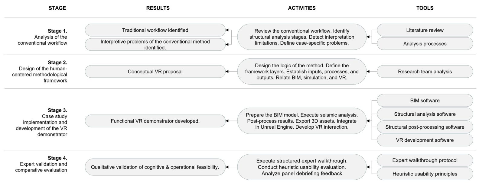
This study was structured as a four-stage research process aimed at identifying the limitations of the conventional structural analysis workflow, designing a human-centered methodological framework, implementing it through a case study, and comparatively analyzing the resulting immersive solution. Figure 1 schematically illustrates the overall research methodology. The methodological logic of the study was sequential: first, the conventional workflow was examined in order to establish the analytical baseline and identify its main interpretive limitations; second, a human-centered methodological framework was defined to integrate BIM models, nonlinear seismic simulation results, and virtual reality into a single immersive environment; third, the framework was implemented through a case study based on a generic nuclear power plant, resulting in a functional VR demonstrator; and fourth, the proposed workflow was evaluated using a qualitative, expert-driven approach to examine its cognitive and operational feasibility. Rather than performing a broad quantitative user study, which is often premature for early-stage digital prototypes [32], the validation relied on an expert walkthrough protocol combined with heuristic evaluation principles adapted for immersive environments [47,48]. A panel of structural engineering specialists and seismic simulation experts evaluated the functional VR prototype. The panel interacted with the system in both mock-up and scale-real (1:1) configurations, evaluating how the immersive platform addresses the analytical gaps identified in conventional desktop post-processing. Their feedback was mapped against the qualitative criteria described in Table 1 to assess spatial understanding, internal damage visibility, traceability, state comparison, and technical communication support.
Rather than focusing on numerical performance measurement, the methodology was oriented toward a structured comparative analysis of how each workflow supports structural interpretation, state comparison, inspection conditions, and technical communication. In this sense, the method combined conceptual design, prototype development, and demonstrative analysis in order to examine the transition from a traditional data-centric workflow to a human-centered immersive workflow.
To support the comparative analysis carried out in the fourth stage, a set of qualitative criteria was defined. The criteria provided a qualitative framework to examine perceived differences between conventional and immersive workflows differ in terms of structural interpretation, spatial understanding, inspection capabilities, and technical communication. The criteria were derived directly from the research gaps identified in the introduction and from the objectives of the study. Figure 1 summarizes the stages developed in the research, including the main results obtained, the activities performed, and the tools involved in each stage.
These criteria were applied qualitatively to both the conventional workflow and the immersive workflow developed in this study. For each criterion, the analysis examined how the traditional approach addressed the corresponding interpretive need and how the proposed VR environment modified or improved that condition. The goal of this application was to identify and analyze the observable differences between the two workflows. In the Results and Analysis Section, these same criteria are reused as an analytical lens to examine the demonstrative contribution of the immersive implementation with respect to the conventional COMPACK–GiD workflow.

3. Proposal: Four-Stage Data Transformation Pipeline Framework

This section presents the methodological proposal developed in this study, organized in a way that makes explicit the transition from a traditional data-centric structural analysis workflow to a human-centered immersive workflow. First, the conventional process based on pre-processing, numerical solving, and post-processing is described in order to establish the analytical baseline and identify its main interpretive limitations. Next, the proposed framework is introduced as an alternative integration strategy that combines BIM models, nonlinear seismic simulation results, and virtual reality within a single immersive environment aimed at structural interpretation, risk-free inspection, and technical communication. In this way, the section not only describes the components of the proposed solution but also clarifies the methodological differences with respect to the conventional workflow.

3.1. Traditional Workflow for Structural Analysis and Post-Processing

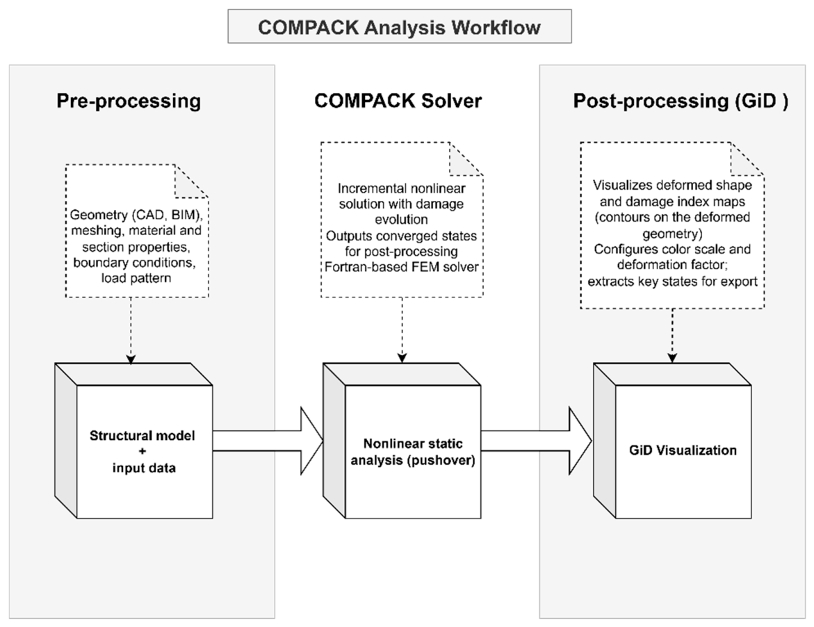
The traditional workflow for nonlinear seismic structural analysis follows a predominantly data-centric logic and can be described in three main stages: pre-processing, numerical solving, and post-processing. Figure 2 schematically illustrates this process. In the first stage, the structural model is prepared from CAD- or BIM-based geometry and meshing environments, together with the input data required for analysis, including material properties, section properties, boundary conditions, and load patterns. These elements collectively define the structural dataset that serves as the basis for the numerical simulation. In the second stage, the model is solved using a finite element analysis engine. In the implementation case considered in this work, the nonlinear static pushover analysis is carried out through COMPACK by QUANTECH [49], an explicit branch of the structural analysis environment developed within the CIMNE framework [50]. This stage produces the incremental nonlinear solution, including the evolution of structural response and the set of converged states required for post-processing.
In the third stage, the simulation results are inspected using conventional post-processing software, such as GiD [12]. At this point, the analyst visualizes deformed configurations, contour maps, damage distributions, section cuts, and capacity curves, and extracts the states considered most relevant for interpretation. Although this workflow supports detailed technical analysis and remains fully integrated into standard structural engineering practice, its interpretive capacity depends strongly on the analyst’s ability to navigate fragmented 2D or non-immersive 3D views and mentally reconstruct the relationship between geometry, structural states, and numerical outputs. As a result, comparison between structural states, tracing of nonlinear events, and communication of findings often require additional manual work outside the visualization environment.
To establish the technical positioning of the proposed framework relative to the state of the art, Table 2 presents a comparative matrix contrasting existing structural inspection and post-processing paradigms across six functional dimensions.

3.2. Human-Centered Methodological Proposal

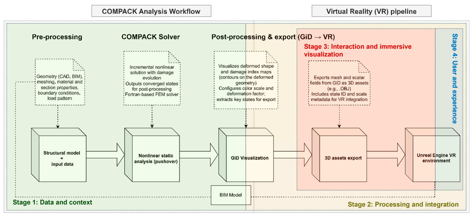
Rather than an encapsulated software layered structure with strict concentric wrapping, the proposed framework establishes a four-stage sequential data transformation pipeline. In this pipeline, structural simulation results and BIM geometry flow progressively from raw analytical outputs, through polygonization and spatial alignment, to real-time rendering, and finally to human-centered interaction logic. Figure 3 schematically illustrates the four-stage data transformation pipeline.
The proposal of this work consists of a human-centered methodological framework for integrating BIM models and seismic simulation results into a virtual reality environment oriented toward structural interpretation, risk-free inspection, and technical communication in nuclear power plants. Unlike conventional workflows, in which the asset geometry and the results of structural analysis are processed and visualized in separate environments, the proposed approach articulates both sources of information within an immersive interface that allows structural behavior to be explored in a spatially coherent and contextualized manner.
The method is organized around a four-layer framework, adapted to the case of a generic nuclear power plant and operationalized through an integration workflow that connects the results of nonlinear seismic analysis with a BIM environment deployed in Unreal Engine [56]. This workflow can be summarized as FEA/GiD → BIM/UE → immersive VR environment, where each component fulfills a specific function within the process of preparing, integrating, visualizing, and interacting with structural data. Figure 3 schematically illustrates the main elements of the proposed framework.

3.2.1. Stage 1: Data Preparation and BIM/FEA Contextualization

The first layer corresponds to the collection, preparation, and contextualization of the data required to build the virtual environment. At this stage, two main sources of information are integrated. On the one hand, a reference BIM model of the nuclear power plant is incorporated, representing the spatial context of the asset and providing a geometric and semantic basis for navigation and analysis. On the other hand, the results of nonlinear seismic analysis are integrated as the system’s dynamic structural information source. In the implementation case, these results come from simulations performed with COMPACK and post-processed in GiD, where deformed configurations, contour maps, and representative analysis states are generated, prioritizing the final collapse state and the Mechanical Damage Index as the main visualization variable. These results are then exported as 3D files compatible with the immersive visualization workflow.
From a methodological perspective, this layer defines the foundation of the system: the physical context of the asset and the simulated structural behavior to be interpreted. In this sense, the proposal does not start solely with navigable geometry or from isolated numerical results, but from the articulation between both elements as a condition for richer structural interpretation.

3.2.2. Stage 2: Data Conversion and Asset Integration

The second layer corresponds to the processing and integration of information into the immersive environment. At this stage, the BIM model is imported into Unreal Engine through Datasmith, while the structural results exported from GiD are incorporated as independent 3D meshes, conceived as “mock-ups” of specific structural states. The process includes the spatial alignment of these mock-ups with respect to the main BIM model, ensuring geometric coherence and consistency between the reference state and the states resulting from the analysis. Likewise, geometry adjustments, material setup, and overall optimization of the environment are carried out to support smooth performance in virtual reality.
This layer is key because it transforms a set of originally dispersed data into an integrated digital environment, where BIM geometry and analysis results can coexist within the same interaction space. From the methodological point of view, this is where the transition is achieved from a traditional simulation workflow to an interactive analysis platform.

3.2.3. Stage 3: Immersive Rendering and Spatial Visualization

The third layer corresponds to the design of the immersive interface and to the way in which the user interacts with structural information. The proposal is implemented in a VR environment centered on a VRPawn locomotion framework, aimed at managing navigation, exploration, and comparison of results. The user can move through the environment by means of teleportation and/or free flight, interact with the BIM model at 1:1 scale, and visualize the structural mock-ups derived from the seismic analysis.
One of the most relevant elements of this layer is the immersive comparative method. To facilitate detailed interpretation, the result mock-ups are duplicated and scaled to full size, being positioned next to the main BIM model or superimposed with different levels of transparency. This makes it possible to compare, in an immersive manner, the original geometry of the asset with the deformed configuration or with the damage maps generated in the simulation, thereby facilitating the identification of critical zones and the understanding of complex structural mechanisms. In addition, the proposal includes inspection tools applied to specific elements of the model, such as interaction panels or simulated defects, with potential for future expansion toward measurement, annotation, or more advanced analysis functions. In methodological terms, this layer represents the shift from passive visualization to immersive structural interaction, in which the user does not merely observe results, but navigates through them, contrasts them, and interprets them in relation to the physical context of the asset.

3.2.4. Stage 4: User Interface, User Experience, and Interaction Logic

Grounded in the ISO 9241-210 human-centered design standard [57] for interactive systems and Sweller’s Cognitive Load Theory [58], Stage 4 establishes the operational interaction logic and user experience framework. User Interface (UI) and User Experience (UX) are explicitly distinguished from an engineering perspective. The UI encompasses spatial 3D interaction widgets (3D clipping planes, ray-cast telemetry panels, 1:1 scale teleportation locomotion, and virtual measurement tools) implemented within Unreal Engine 5. The UX focuses on reducing extraneous cognitive friction, as defined in spatial visualization ergonomics, by collocating non-linear damage scalar fields (d) directly onto 1:1 scale BIM geometry. This replaces the mental synthesis of fragmented 2D post-processing cuts with direct, situated spatial perception.
Furthermore, Stage 4 establishes the operational boundary for safe virtual inspection. From a system design standpoint, artificial intelligence modules, such as conversational cognitive assistants for automated querying of BIM and simulation data, were not implemented in the current operational pipeline. Within a broader digital twin framework, such AI modules constitute an external cognitive interaction layer designed to operate atop Stage 4, representing a key direction for future research.

3.3. Synthesis of the Differences Between Both Workflows

The main difference between both approaches lies in the role assigned to structural information and to the user. In the traditional workflow, results are generated and inspected through separate, mainly screen-based tools, requiring the analyst to mentally reconstruct structural meaning from fragmented outputs. In the proposed workflow, BIM geometry and simulation results are articulated within a single immersive interface, where interpretation is supported through direct spatial interaction, full-scale comparison, and contextualized exploration. As a result, the proposed method moves from a data-centric logic to a human-centered workflow that emphasizes structural understanding, risk-free inspection, and technical communication.

4. Results and Analysis

4.1. Overview of the Case Study Implementation

In order to operationalize the proposed methodological framework, a case study was developed and implemented as a functional virtual reality demonstrator aimed at structural interpretation and safe inspection in a generic nuclear power plant. The purpose of the implementation was to materialize, within an immersive environment, the integration between the geometric context of the asset represented through a BIM model and the results of nonlinear seismic analyses obtained from advanced structural simulation. In this way, the case study made it possible to move the proposal from a conceptual level to an interactive solution capable of representing, exploring, and comparing relevant structural states within a single digital environment.
From a technical perspective, the implementation involved the preparation of the reference BIM model, the generation and post-processing of representative structural results, their export as 3D assets, their spatial integration and alignment in Unreal Engine, and the development of an immersive experience navigable through virtual reality devices. This experience included both the general visualization of the plant environment and the detailed inspection of deformed structural models, damage maps, and simulated pathologies, allowing users to move through the asset at different scales and contrast reference states with post-simulation states within a single session of use. To present this implementation, the section is organized into two complementary parts: (1) First, the conventional structural analysis workflow and the main interpretation problems identified when using traditional post-processing tools are described. (2) Second, the virtual reality implementation workflow is presented, including the integration of the BIM model and seismic results, the functionalities developed, and the technical deployment of the prototype. In this way, the section aims to show how the case study materializes the methodological proposal and how the resulting immersive experience responds to the limitations observed in conventional approaches.

4.2. Structural Analysis Requirements of the Case Study and Limitations of Their Conventional Interpretation

For the implementation of the case study, the proposed method relies on results obtained from nonlinear static pushover analyses, aimed at studying the structural response of the facility under extreme scenarios. These analyses make it possible to characterize both the global and local behavior of the structure, including the evolution of displacements, drifts, progressive degradation, damage concentration, plasticization, and the formation of collapse mechanisms. Therefore, their interpretation requires not only access to numerical outputs, but also visualization means capable of consistently linking the global response of the system with the local phenomena that explain it.
The finite element model used to generate the structural states integrated into the VR demonstrator comprised 181,191 nodes and 324,150 finite elements. The distribution of the minimum element edge length ranged approximately from 0.32 to 0.80 m, with most shell elements concentrated around 0.50 m. The main reinforced-concrete structural components, including slabs, walls, beams, and columns, were represented using three-node rotation-free triangular shell elements [59]. Reinforced concrete was described through the serial/parallel mixing theory [60], combining an isotropic damage formulation for concrete with an elastic-perfectly plastic formulation for the steel reinforcement. This constitutive representation captures progressive concrete cracking and stiffness degradation together with yielding of the reinforcement. The main mechanical and constitutive properties adopted in the nonlinear model are summarized in Table 3.
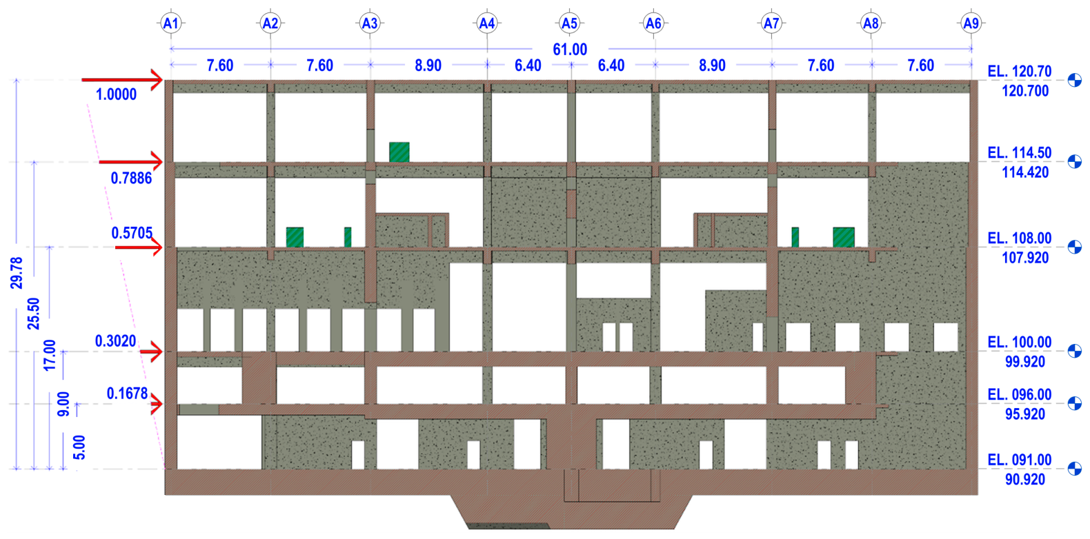
The nonlinear static analyses were performed on a fixed base. A master node was kinematically linked to all support nodes, restraining the base degrees of freedom and providing the reference point from which the base shear was obtained. The lateral response was evaluated independently in the two principal horizontal directions, X and Y. Incremental prescribed displacements were applied to all nodes of each floor according to a height-proportional triangular distribution, with the maximum value at the uppermost floor, as illustrated in Figure 4. The displacement was read at a representative node of the uppermost floor and adopted as the control variable, whereas the base shear was read at the master node and adopted as the resistant variable. The analysis continued beyond peak resistance until the base-shear capacity had decreased by 20% relative to its maximum value; this condition was adopted as the collapse and termination criterion.
The Mechanical Damage Index (d) used in the visualization is a local scalar internal variable associated with material stiffness degradation. Following the isotropic damage formulation, the constitutive response is expressed as
σ = 1 d C 0 :   ε ,       0   d     1
where C0 is the elastic constitutive tensor of the undamaged material. Accordingly, d = 0 represents intact material, intermediate values represent partial stiffness degradation, and d = 1 represents complete degradation of the undamaged elastic stiffness contribution under the adopted constitute idealization. For the VR workflow, the field selected in GiD was the post-processing result labelled “Average damage”, displayed using the “Smooth Contour Fill (Mean)” representation. The deformed geometry was visualized and exported with a deformation scale factor of 1.0; no additional displacement amplification was applied in GiD or Unreal Engine.
In practice, however, the interpretation, discussion, and communication of these results are still carried out mainly through conventional post-processing tools such as GiD, supported by non-immersive 2D or 3D views, contour maps, section cuts, and static screenshots. Although these tools enable detailed technical analysis, they present important limitations when the goal is to achieve an integrated understanding of structural behavior, compare structural states without losing spatial context, and transfer findings into technical discussion or decision-making processes. Based on the implementation case, four main interpretation challenges were identified. Figure 5 summarizes the structural analyses considered and the corresponding result interpretation problems associated with each of them.
  • Problem 1. Limited Visibility of Internal Damage. One of the main limitations of conventional post-processing environments is the difficulty of clearly inspecting damage in internal elements, especially in inner walls or areas hidden from external views. In practice, the standard exploration mode favors external inspection of the model, while internal damage assessment requires repeated use of section cuts, slicing planes, and manual viewpoint changes. This fragments the analysis process and makes it difficult to reconstruct the spatial distribution of damage in an integrated manner.
  • Problem 2. Limitations of Flat-Screen Visualization for Understanding Complex Spatial Relationships. Although tools such as GiD provide 3D capabilities and allow the generation of deformed shapes, damage maps, and dynamic section planes, interaction remains constrained by the logic of the flat screen. This limits the perception of depth, scale, and complex geometric relationships between structural elements, particularly when interpreting damage mechanisms, crack propagation, or comparing deformed configurations with the reference state. As a result, spatial understanding depends largely on the analyst’s ability to mentally reconstruct the three-dimensional context.
  • Problem 3. Insufficient Pseudo-Immersion for Structural Interpretation. Some tools incorporate pseudo-stereoscopic modes or alternative visualization options intended to improve spatial perception; however, these solutions remain far from the level of immersion and spatial precision provided by a genuine virtual reality environment. The absence of a dynamic perspective linked to the user’s natural movement limits embodied spatial perception and reduced the ability to explore the model from meaningful positions for technical interpretation. Consequently, these approaches do not effectively resolve the gap between structural data and its direct spatial understanding.
  • Problem 4. Difficulty in Assessing Advanced Damage and Collapse States. In pushover scenarios, interpreting structural behavior in advanced damage states becomes particularly complex when it is performed through non-immersive 2D or 3D visualization. Reading the Mechanical Damage Index, identifying critical zones, and observing cracking or progressive degradation are all limited by the lack of direct interaction with the model. In addition, these tools generally do not allow intuitive crack inspection or meaningful spatial measurements over the damaged geometry. This reduces the ability to examine collapse evolution in detail and limits the potential of the results to support technical assessment, communication, and decision-making processes.
Taken together, these limitations show that the challenge lies not only in generating advanced simulation results, but also in providing an environment that allows them to be interpreted in a spatially coherent way, compared without losing context, and communicated more effectively. From this perspective, the immersive workflow presented in the following subsection is intended to address these limitations by articulating the reference BIM geometry with seismic analysis results within a virtual reality interface oriented toward structural understanding, risk-free inspection, and human-centered interaction.

4.3. Immersive VR Workflow and Prototype Deployment

The immersive implementation was developed by integrating the reference BIM model and the structural results derived from nonlinear seismic analysis into a single VR environment built in Unreal Engine. The workflow was executed in five sequential stages: (i) export and preparation of the BIM model, (ii) generation and post-processing of representative seismic analysis states, (iii) integration and spatial alignment of assets in Unreal Engine, (iv) development of immersive interaction functionalities, and (v) compilation and testing of the prototype.
First, the BIM model of the nuclear power plant was exported from Autodesk Revit® [61] through Datasmith [62] and prepared for real-scale deployment in Unreal Engine. Once the reference BIM model was available, the nonlinear pushover analysis results were processed in GiD to generate static 3D structural assets corresponding to representative states of the analysis, including deformed geometries and contour-based damage visualizations. These states were exported as 3D meshes in .obj format, preserving the information needed to reproduce their appearance and enable comparison with the BIM model in the immersive environment. Second, both the BIM model and the structural result mesh were imported into Unreal Engine. The BIM model was deployed at 1:1 scale as the main spatial reference of the environment, while the structural models were incorporated at different scales, including mock-up scale and full-scale representations. A spatial alignment process was then carried out to maintain geometric correspondence between the models exported from GiD and BIM geometry. In parallel, geometry, materials, and rendering settings were adjusted to improve visual quality and maintain stable performance under VR conditions.
Third, the immersive interaction functionalities were implemented. These included navigation through teleportation and free-flight locomotion, comparative visualization between the BIM reference model and the structural result models, duplication and full-scale display of selected structural states, and grab-based interaction for manipulating specific assets. In addition, an inspection subsystem was incorporated through crack decals and interaction panels, allowing the user to inspect simulated damage patterns and interact with selected elements of the environment. At the functional level, the prototype included a seismic analysis mode, focused on the exploration of deformations and damage maps; an inspection mode, oriented toward the review of simulated pathologies; and a training-oriented mode, conceived as a basis for future emergency scenarios such as smoke or fire.
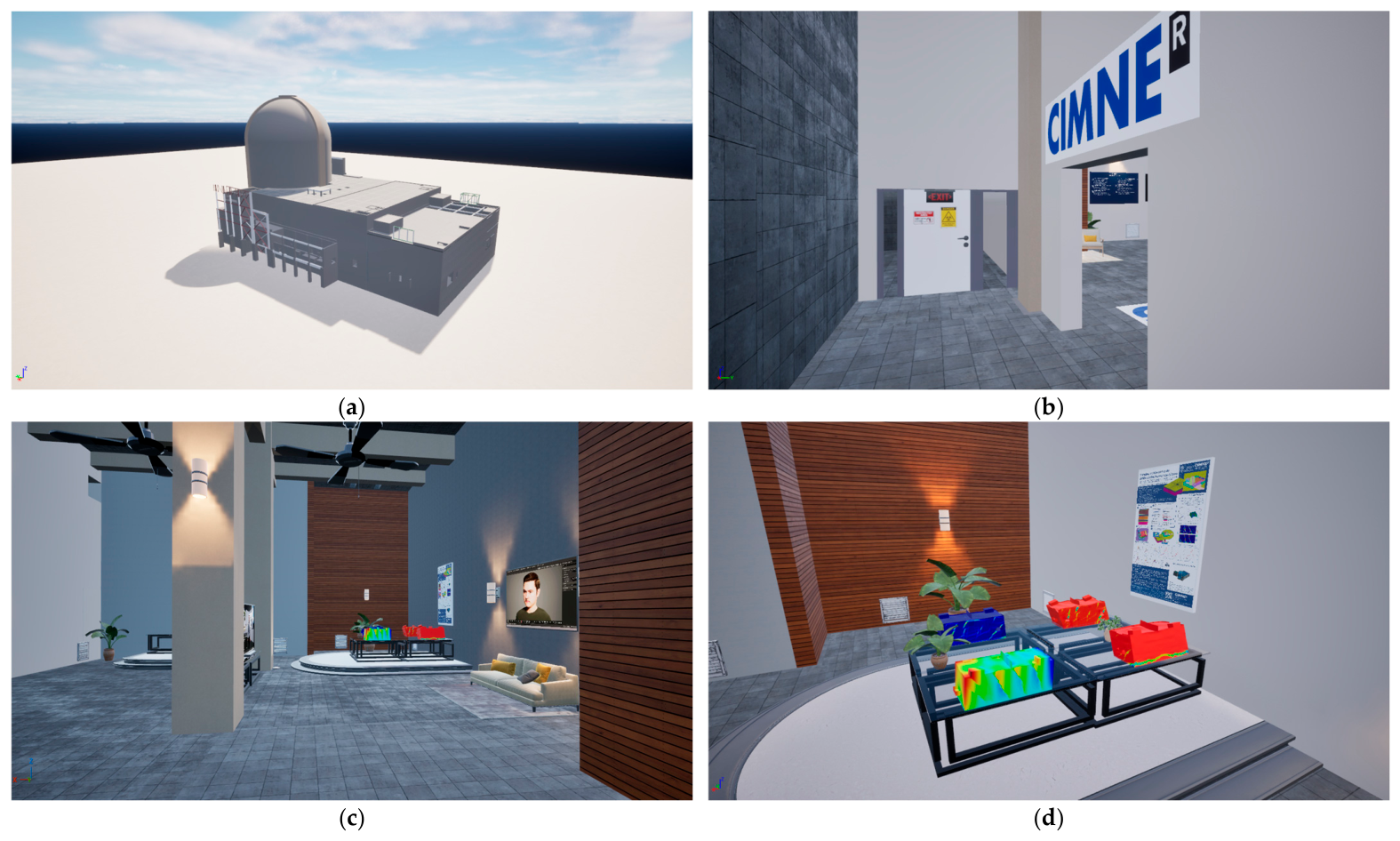
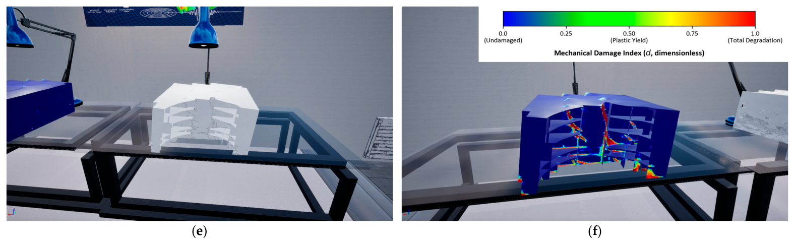
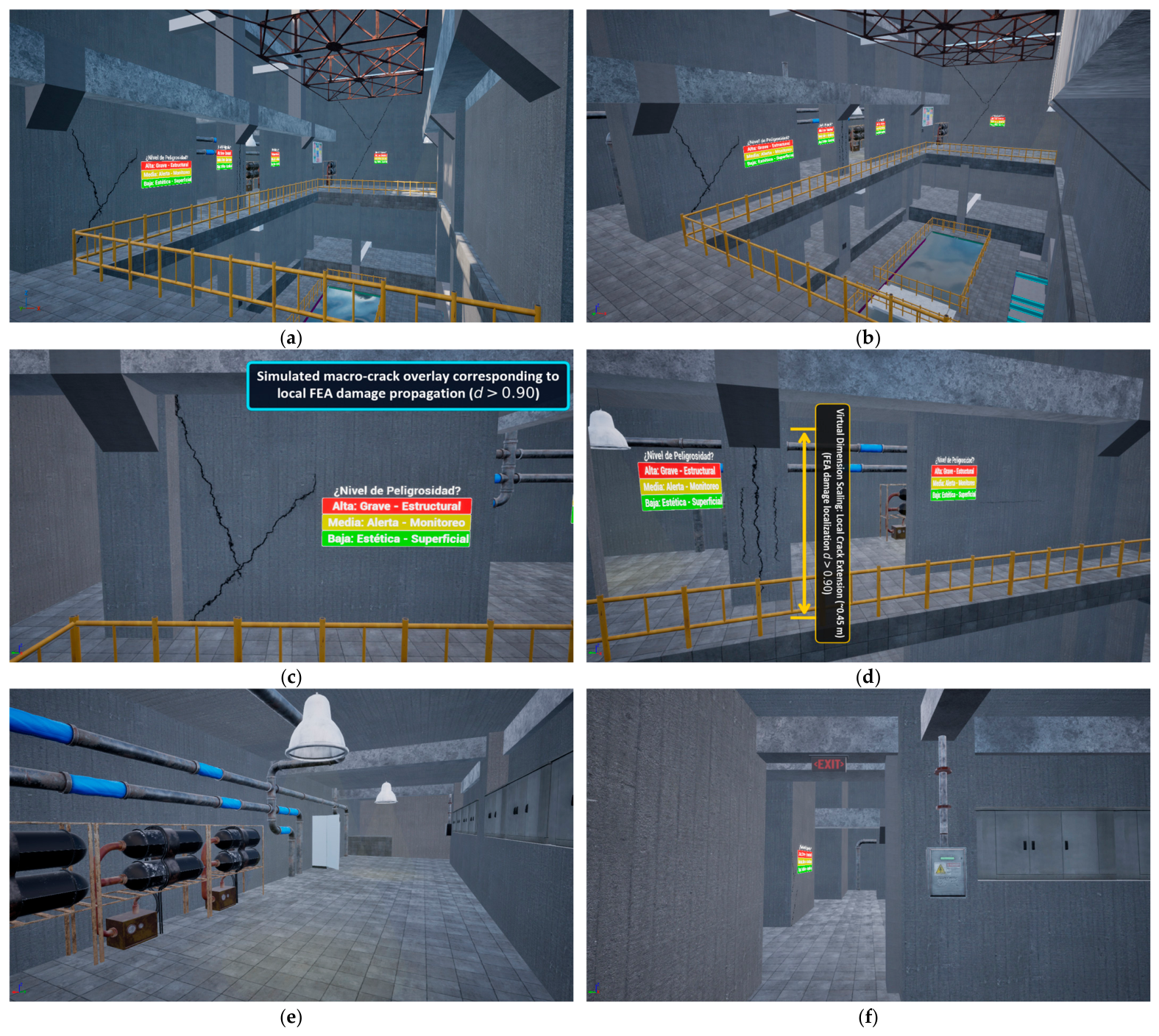
From the user’s perspective, the VR experience is structured as a guided inspection sequence that progressively moves from global spatial understanding to detailed structural review. As shown in Figure 6, the session begins with a small-scale 3D model of the nuclear power plant (Figure 6a), which provides an overall view of the facility and its spatial organization. The user then transitions into the plant at full scale (Figure 6b), enabling direct navigation through the environment at 1:1 scale. This is followed by access to an information room (Figure 6c), where the inspection context is introduced and the user is prepared to interact with the structural analysis content. Next, numerical models are presented within the VR environment (Figure 6d), allowing the user to inspect simulation-derived representations of the structure. At this stage, the experience focuses on the visualization of deformed structural states (Figure 6e) and stress-related states (Figure 6f), providing an immersive analytical context for understanding the structural response. As shown in Figure 7, the second part of the experience shifts toward inspection-oriented interaction within the plant.
The user first observes a general inspection view of the nuclear facility in VR (Figure 7a), followed by a similar view enriched with cracks and interaction panels that introduce specific inspection tasks (Figure 7b). The experience then directs attention to localized damage patterns, including diagonal cracks in a wall (Figure 7c) and vertical cracks in a column (Figure 7d), enabling closer observation of representative structural pathologies. Finally, the sequence expands again toward a general view of the plant facilities (Figure 7e) and concludes with navigation through the interior of the plant (Figure 7f), marking the end of the VR inspection session. In this way, the prototype combines global orientation, immersive structural result visualization, and localized damage inspection within a single coherent workflow.
Finally, the prototype was compiled for PC-based virtual reality and tested iteratively using a Meta Quest 3 headset [63] connected via Steam Link [64]. This stage focused on verifying environment stability, interaction consistency, navigation fluidity, and the correct deployment of BIM and structural result assets under real VR conditions. The resulting demonstrator reached a functional level suitable for expert-based validation in the subsequent stage.
To ensure technical replicability and document information transformation across data formats, Table 4 details the specifications of the data conversion pipeline, execution hardware platform, preserved attributes, and rendering performance parameters of the implemented prototype.

4.4. Analysis of the Proposed Method and Implementation

To support the technical validity and operational relevance of the qualitative evaluation, the proposed immersive environment was tested by a panel of five (5) selected experts with extensive background in structural engineering, seismic simulation, and virtual design workflow management. Due to the highly specialized nature of nuclear infrastructure, a purposive sampling method was employed to recruit evaluators with active research and professional background in advanced numerical solvers and interactive environments. Table 5 summarizes the anonymized professional profiles of the evaluation panel, including their specific roles, academic titles, years of experience, and primary fields of expertise.
This multidisciplinary composition of the panel allowed the evaluation to cover both the strict engineering performance criteria (e.g., how accurately the virtual environment represents structural damage inside the shear walls) and the usability/cognitive criteria (e.g., how effectively the interface reduces spatial fragmentation during navigation).
The evaluation of the implemented case study was carried out through a structured walkthrough with the expert panel. The structural and seismic simulation specialists tested the prototype using a Meta Quest 3 headset, executing the guided inspection sequence described. Following the evaluation, a debriefing session was conducted to document the specialists’ feedback regarding the comparative criteria. The main findings and perceived interpretive shifts reported by the experts are synthesized in Table 6 which synthesizes the main observed differences between the traditional COMPACK–GiD workflow and the immersive implementation.
Regarding the spatial understanding of structural behavior (Criterion 1) and the visibility of internal damage (Criterion 2), the experts indicated that the 1:1 scale exploration facilitates a more immediate and continuous interpretation of kinematic failure mechanisms. Under conventional desktop workflows, analyzing damage inside thick concrete shear walls requires a high level of mental abstraction to stitch together fragmented slicing planes. One of the structural analysts on the panel noted: “In conventional post-processing, visualizing the mechanical damage index inside heavy concrete walls requires a high level of mental abstraction to stitch together 2D planes. Walking through the collapsed virtual structure allows an intuitive and continuous interpretation of the failure mechanism, preserving its spatial coherence.”
For the comparison of structural states (Criterion 4) and the evaluation of advanced collapse scenarios (Criterion 5), the panel highlighted the usefulness of interacting with dual-scale models. Being able to manipulate the small structural mock-ups while having the corresponding 1:1 scale damaged geometry superimposed on the BIM reference model reduced the cognitive fragmentation typical of desktop interfaces.
Furthermore, the experts pointed out that the VR demonstrator introduces a significant advantage for interdisciplinary technical communication (Criterion 8). While standard finite element (FEM) post-processing outputs are highly specialized and often incomprehensible to non-expert stakeholders, the VR environment translates numerical damage data into visually intuitive pathologies contextualized within the plant’s physical geometry. As one safety manager from the panel remarked: “This interface bridges the gap between the simulation analyst and other stakeholders. It allows us to present a complex seismic push-over result to safety managers or plant operators without the need to translate abstract color contour scales or numerical reports, keeping the operational context intact.”
Another important aspect concerns traceability between the global response of the structure and the local mechanisms that explain it. In the conventional workflow, capacity curves, contour plots, deformed configurations, and damage states are often reviewed separately, making it difficult to directly associate a global response stage with the corresponding local events. In the immersive workflow, however, selected structural states are examined in relation to the BIM reference model and within the surrounding spatial context of the asset. This improves interpretive continuity by helping the user understand how localized damage patterns or deformations correspond to broader response conditions. As shown in Table 6, this represents an improvement in the traceability of structural meaning, even if engineering interpretation remains necessary for formal technical assessment.
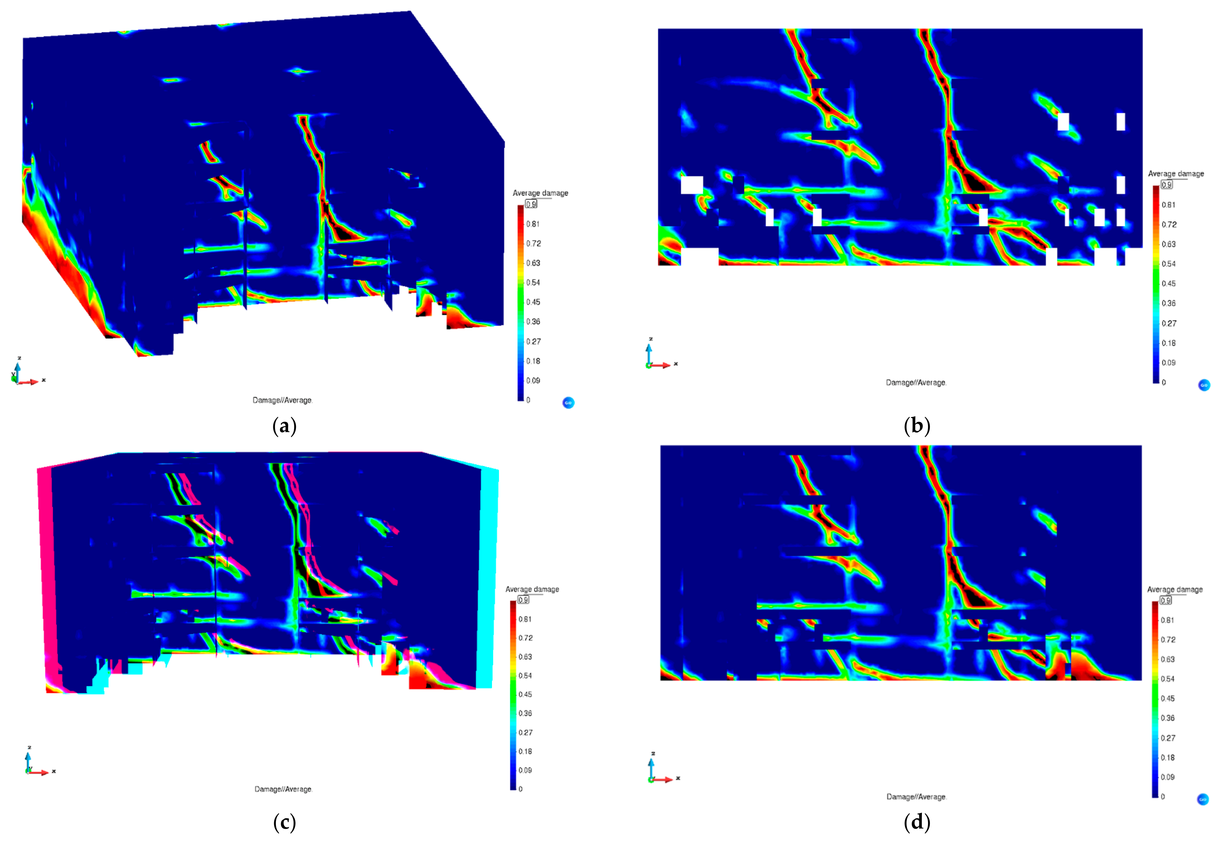
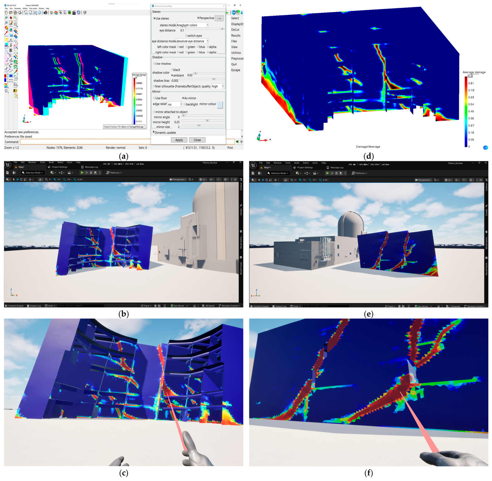
This continuous visual traceability across data environments is demonstrated in Figure 8, which illustrates the multi-stage conversion of structural simulation data arranged in a two-column comparative layout across six panels (a–f). Panels (a) and (b) contrast the global Mechanical Damage Index (d) scalar field in the desktop GiD post-processor (a) with the polygonised 3D asset in the Unreal Engine 5 editor (b). Panel (c) shows the corresponding full 1:1 scale immersive VR environment inspected via Meta Quest 3. Panels (d), (e), and (f) provide a high-resolution localized view of progressive non-linear damage propagation (d ≥ 0.85, color-coded from undamaged blue to total material degradation red). As highlighted in panels (d) and (f), localized shear crack concentrations and plastic degradation zones that require complex 2D clipping planes in GiD (d) become intuitively inspectable and spatially queryable when explored in the 1:1 VR environment (f) adjacent to the reference BIM model.
The comparison between structural states is another area in which the immersive prototype offers a clear advantage. In the conventional workflow, comparison is typically sequential, manual, and dependent on screenshots, synchronized views, or the analyst’s memory of previous structural states. In the implemented VR environment, the BIM reference model and the structural result mock-ups can be reviewed within the same session and in the same contextualized environment, including small-scale views and full-scale inspection. This allows differences between reference and damaged or deformed states to be identified more directly and reduces the fragmentation that characterizes desktop-based workflows. Table 6 reflects this by showing that the immersive workflow supports more immediate and coherent comparison between structural conditions.
The interpretation of advanced damage and collapse-related states also benefits from the immersive implementation. In the traditional workflow, severe degradation conditions, crack progression, and variables such as the Mechanical Damage Index are difficult to interpret because the analyst must infer structural meaning from screen-based visualizations and indirect inspection operations. In the prototype, these states are transformed into 3D structural assets that can be explored in an immersive manner and in direct relation to the geometry of the plant. This makes advanced damage conditions easier to inspect, discuss, and contextualize. Table 6 indicates that the immersive workflow provides a more accessible setting for understanding collapse-related behavior, especially when compared with conventional static or non-immersive post-processing views.
A central distinction between both workflows lies in the degree of user interaction with structural results. In the conventional approach, the user mainly observes results through desktop interfaces, navigating between windows, cuts, and plots. In the immersive prototype, the user actively navigates through the facility, changes viewpoint through embodied movement and VR controls, compares structural result models, and interacts with selected elements such as panels and simulated cracks. This shift from passive observation to active exploration is one of the core differences highlighted in Table 6. It reflects the transition from a workflow centered on data display to one in which structural understanding is supported through interaction.
The risk-free inspection capability of the immersive workflow constitutes another major point of difference. The conventional workflow remains analytically useful but detached from the experiential conditions of inspection and does not directly address the risks associated with accessing real facilities. In contrast, the VR implementation enables structural review and inspection tasks to be performed within a controlled virtual environment, without exposure to radiation, confined spaces, or other hazardous conditions associated with nuclear infrastructure. Table 6 shows that this is not only a usability improvement, but also an operational contribution of the proposed method, especially in contexts where inspection access is difficult or risky.
Finally, the qualitative feedback suggests that the immersive workflow offers support for technical communication. Traditional post-processing tools typically communicate findings through contour plots, screenshots, and technical reports, which can fragment context and make discussion more difficult across different users. In the immersive environment, BIM geometry, structural states, damage indicators, and inspection cues coexist within a single contextualized interface. This facilitates clearer explanation of findings and provides a more coherent basis for communicating complex structural conditions. As summarized in Table 6, the proposed workflow strengthens the communication of technical information not only because it shows the results differently, but because it organizes them within a more interpretable and shared spatial environment.

5. Discussion

5.1. General Discussion: Interpretation of the Main Findings

The qualitative findings of this study suggest that the primary value of the proposed integration lies in the transformation of the interpretive logic rather than the immersive visualization alone. In conventional workflows, structural interpretation is a highly fragmented process that relies on the analyst’s cognitive capacity to mentally synthesize separate outputs. The qualitative evaluation indicates that the proposed workflow shows potential to mitigate this spatial fragmentation by organizing geometry, simulated structural damage, and user interaction within a unified spatial context.
These results are consistent with previous human-centered research in civil engineering interfaces [26,43], suggesting that situated, full-scale visualizations help bridge the cognitive gap between numerical models and the physical asset. However, as noted by the expert panel, the immersive environment is not intended to replace standard structural software. Solving engines (such as COMPACK) and detailed numerical post-processors (such as GiD) remain essential for formal engineering calculations. Instead, the virtual world serves as a complementary, human-centered layer that facilitates data exploration, interdisciplinary evaluation, and collaborative decision-making in safety-critical environments.
Furthermore, the specialists’ feedback highlights the operational relevance of this transition for risk mitigation and maintenance planning. In safety-critical facilities such as nuclear power plants, structural anomalies or progressive degradation are highly time-sensitive. Standard practices involve translating static outputs into multi-disciplinary reports, which can introduce delays or communication errors between structural experts and facility managers. By centralizing the analytical results within a high-fidelity, interactive spatial reference, the proposed platform potentially reduces the cognitive effort required to discuss local damages in relation to global structural stability. This shared cognitive frame of reference could streamline the collective assessment of complex deformation patterns, demonstrating that human-centered interfaces are crucial not only for individual interpretation but also for joint decision-making processes under high-consequence scenarios.

5.2. Specific Discussions

  • The first specific contribution concerns structural result interpretation. The immersive workflow shows potential to enhance the understanding of damage, deformations, and advanced structural states by reducing dependence on mental reconstruction from screen-based desktop views. In conventional post-processing, structural understanding relies on cognitive effort applied over fragmented 2D outputs; in contrast, the immersive workflow supports spatial interpretation through situated 3D exploration. This capability is particularly relevant for advanced degradation states, where the spatial geometry of material failure provides essential context for interpreting numerical scalar fields, as demonstrated by the visual traceability comparison across data environments in Figure 8.
  • A second contribution relates to risk-free virtual inspection in critical infrastructure. Physical access to nuclear power plant facilities involves strict operational constraints, confined spaces, and potential hazard exposure. While the immersive environment does not replace physical inspection, it provides a controlled virtual setting in which structural states, critical shear walls, and damaged areas can be reviewed without physical exposure to operational risks. This extends the role of the virtual environment beyond data presentation, positioning it as a complementary inspection medium for safety-critical facilities.
  • A third contribution concerns technical communication across multidisciplinary roles. Standard structural simulation outputs are effective for numerical specialists, yet they remain challenging to communicate across operational, safety, or executive decision-making levels. By articulating reference BIM geometry, numerical damage fields, and visual inspection cues within a single 1:1 scale environment, the VR workflow provides a shared spatial basis for explaining structural conditions. This integrated representation supports internal engineering evaluation while facilitating the transfer of technical insights to maintenance planning, asset management, and safety protocols.
In relation to previous studies in the literature, the present study occupies a distinct position within the state of the art, as synthesized in the comparative analysis in Table 1. The proposed framework extends traditional FEA post-processors by introducing full-scale immersive contextualization, while differing from conventional VR applications focused primarily on reality capture or procedural training. By centering the interaction logic on the exploration of predictive non-linear structural analysis results, this study demonstrates a concrete integration pipeline connecting COMPACK/GiD simulations, BIM reference models, and Unreal Engine 5 PC-VR environments in a high-risk infrastructure domain.
Finally, the findings suggest relevant implications for both engineering practice and future research. In practice, the framework demonstrates a methodological path to connect numerical structural simulation outputs directly with virtual inspection, technical discussion, and decision support. In research, it establishes a foundation for immersive structural interpretation that may evolve toward automated data pipelines, real-time sensor updates, collaborative multi-user environments, and cognitive AI interaction modules. Consequently, this work represents a demonstrative step toward more human-centered structural analysis environments in critical infrastructure engineering.

5.3. Limitations

This study has several limitations. First, the work is based on an initial prototype and on a generic nuclear power plant case, so it does not capture the full operational and geometric complexity of a real facility. Second, the current implementation still depends on a partially manual integration process, including the export of structural states as 3D assets and their subsequent alignment and deployment in Unreal Engine; in addition, the prototype remains constrained by the current VR setup and by the level of functionality implemented at this stage. Third, the validation presented in this study is qualitative and based on a structured expert walkthrough with a limited panel of structural specialists. Consequently, the findings regarding improved cognitive performance and technical communication represent perceived advantages rather than quantitatively measured metrics. These limitations are typical of early-stage proof-of-concept implementations and frame the boundaries of our methodological contribution.
To address these limitations, future research will focus on executing systematic, quantitative usability experiments. This subsequent phase will involve larger groups of participant users (including structural engineers, plant operators, and safety managers) to quantitatively measure cognitive workload using the NASA Task Load Index (NASA-TLX) [65] across conventional and immersive workflows. Additionally, objective metrics such as task-completion times, error rates during damage inspection, and eye-tracking visual attention analysis will be evaluated to establish a rigorous quantitative evaluation of the human-centered HMI platform.
Regarding digital twin frameworks, the current implementation focuses specifically on the data-transformation pipeline connecting non-linear structural FEA outputs, BIM reference geometry, and an Unreal Engine 5 VR environment. Artificial intelligence modules, such as conversational cognitive agents or automated damage detection models, were not implemented in the current prototype demonstrator and represent a promising direction for future research. Subsequent work will explore integrating natural language interaction frameworks into the immersive environment to assist operators during virtual inspection tasks.

6. Conclusions

This study proposed and implemented a human-centered methodological framework for integrating BIM models and nonlinear seismic simulation results into an immersive virtual reality environment for structural interpretation and safe inspection in nuclear power plants. The work addressed a relevant gap in current workflows for critical infrastructure analysis: although structural simulations and BIM-based representations provide increasingly rich information, their conventional desktop interpretation can often rely on data-centric and non-immersive post-processing environments that risk fragmenting spatial understanding and potentially making interdisciplinary technical communication more challenging.
The qualitative results of the case study suggest that the proposed workflow, articulated as FEA/GiD → BIM/UE → immersive VR environment, can facilitate the reorganization of structural result interpretation within a single spatially coherent environment. In particular, the expert evaluation indicated that the immersive implementation has the potential to enhance the contextualized understanding of deformation and damage patterns, support comparison between reference and damaged states, and offer a more intuitive way to inspect advanced structural conditions. In this sense, the contribution of the work lies in exploring how to redefine the relationship between structural data, asset geometry, and user interaction through a human-centered logic, rather than merely presenting a visualization tool.
The study also suggested that the immersive environment can offer operational value beyond structural visualization alone. By enabling inspection tasks in a controlled virtual setting, the prototype has demonstrated potential for supporting risk-free inspection of conditions that would otherwise be associated with difficult access or hazardous contexts. At the same time, the integration of BIM geometry, structural states, and inspection cues within a shared interface could strengthen the communication of complex technical findings and potentially open a more coherent space for interdisciplinary understanding in high-risk infrastructure contexts. At the methodological level, the paper contributes a concrete implementation path for translating a conventional data-centric structural workflow into a human-centered immersive workflow. This is particularly relevant because it provides not only a conceptual proposition, but also a demonstrative case showing how advanced seismic analysis outputs can be connected to an operational VR environment using existing engineering and visualization tools.
The work should nevertheless be understood as proof of concept. Its current scope is limited using a generic nuclear power plant case, a partially manual integration process, and a qualitative panel-based analysis rather than a broad quantitative validation. These limitations do not diminish the relevance of the methodological proposal, but they do define several future research directions. Future work should focus on automating the simulation-to-VR pipeline, extending the framework toward real-time integration with sensors and digital twins, and conducting formal comparative studies to assess the impact of immersive environments on structural interpretation, inspection performance, and technical communication. Additional lines of research may include the incorporation of multi-user collaborative environments, advanced inspection functions such as measurement and annotation, and AI-assisted interaction mechanisms to support querying, interpretation, and generation of dynamic training or emergency scenarios within the immersive environment.

Author Contributions

Conceptualization, M.P.M.; methodology, M.P.M.; software, M.P.M.; validation, J.M.S. and F.M.-L.R.; formal analysis, F.R.C. and C.A.P.L.; investigation, M.P.M.; data curation, M.P.M.; writing—original draft preparation, M.P.M.; writing—review and editing, M.P.M., J.M.S., F.R.C., C.A.P.L. and F.M.-L.R.; visualization, M.P.M.; supervision, J.M.S. and F.M.-L.R.; project administration, M.P.M. All authors have read and agreed to the published version of the manuscript.

Funding

This research was funded by the National Agency for Research and Development (ANID)/Scholarship Program/DOCTORADO NACIONAL/2024-72240171.

Data Availability Statement

The structural finite element models and specific geometric datasets of the nuclear power plant facility contain sensitive infrastructure information and cannot be made publicly available due to safety regulations. However, non-sensitive demonstrator assets, generic 3D meshes, and Unreal Engine 5 prototype scripts are available from the corresponding author upon reasonable request.

Acknowledgments

The first author, Mathias Proboste Martinez, acknowledges the support of the National Agency for Research and Development (ANID). During the preparation of this manuscript, the authors used Gemini (Google) for the purpose of language editing, translation assistance, and manuscript formatting. The authors reviewed and edited the content as necessary and take full responsibility for the content, methodology, and scientific integrity of this publication.

Conflicts of Interest

The authors declare no conflicts of interest.

References

  1. Jyotish, N.K.; Singh, L.K.; Kumar, C.; Singh, P. Reliability and Performance Evaluation of Safety-Critical Instrumentation and Control Systems of Nuclear Power Plant. IEEE Trans. Reliab. 2024, 73, 422–437. [Google Scholar] [CrossRef] [Scilit]
  2. Kumar Jyotish, N.; Kumar Singh, L.; Kumar, C. Reliability Assessment of Safety-Critical Systems of Nuclear Power Plant Using Ordinary Differential Equations and Reachability Graph. Nucl. Eng. Des. 2023, 412, 112469. [Google Scholar] [CrossRef] [Scilit]
  3. Dybach, O. Specific Considerations for Applying Resilience in Nuclear Power Plants. In Proceedings of the 2024 14th International Conference on Dependable Systems, Services and Technologies (DESSERT), Athens, Greece, 11–13 October 2024; IEEE: New York, NY, USA, 2025; pp. 1–5. [Google Scholar]
  4. Hrinchenko, H.; Antonenko, N.; Khomenko, V.; Artiukh, S. Assessment of Power Equipment Operational Safety in the Sustainable Management of Residual Lifespan. Econ. Ecol. Socium 2024, 8, 78–91. [Google Scholar] [CrossRef] [Scilit]
  5. Zhonglin, Z.; Bin, F.; Liquan, L.; Encheng, Y. Design and Function Realization of Nuclear Power Inspection Robot System. Robotica 2021, 39, 165–180. [Google Scholar] [CrossRef] [Scilit]
  6. Yan, R.; Dunnett, S.; Andrews, J. A Petri Net Model-Based Resilience Analysis of Nuclear Power Plants under the Threat of Natural Hazards. Reliab. Eng. Syst. Saf. 2023, 230, 108979. [Google Scholar] [CrossRef] [Scilit]
  7. Baniqued, P.D.E.; Bremner, P.; Sandison, M.; Harper, S.; Agrawal, S.; Bolarinwa, J.; Blanche, J.; Jiang, Z.; Johnson, T.; Mitchell, D.; et al. Multimodal Immersive Digital Twin Platform for Cyber–Physical Robot Fleets in Nuclear Environments. J. Field Robot. 2024, 41, 1521–1540. [Google Scholar] [CrossRef] [Scilit]
  8. Naraghi, N.; Feng, Z.; Lovreglio, R.; Vishnupriya, V.; Wilkinson, S.; Baghaei Daemei, A. Simulating and Visualising Indoor Seismic Damage: A Systematic Literature Review. Int. J. Disaster Risk Reduct. 2024, 115, 104979. [Google Scholar] [CrossRef] [Scilit]
  9. Zhai, G.; Yao, Z.; Wang, D.; Zhang, A.A.; Spencer, B.F.; Xu, Y. Autonomous Post-Earthquake Structural Assessment Based on Bidirectional Graphics-Based Digital Twin (Bi-GBDT) with Physical and Visual Realism. Adv. Eng. Inform. 2026, 69, 103971. [Google Scholar] [CrossRef] [Scilit]
  10. Rodríguez, C.A.; Rodríguez Pérez, Á.M.; López, R.; Caparrós Mancera, J.J. Comparative Analysis and Evaluation of Seismic Response in Structures: Perspectives from Non-Linear Dynamic Analysis to Pushover Analysis. Appl. Sci. 2024, 14, 2504. [Google Scholar] [CrossRef] [Scilit]
  11. Kita, A.; Cavalagli, N.; Masciotta, M.G.; Lourenço, P.B.; Ubertini, F. Rapid Post-Earthquake Damage Localization and Quantification in Masonry Structures through Multidimensional Non-Linear Seismic IDA. Eng. Struct. 2020, 219, 110841. [Google Scholar] [CrossRef] [Scilit]
  12. GID CIMNE GiD Simulation. Available online: https://www.gidsimulation.com/ (accessed on 9 June 2026).
  13. Zhou, T.; Zhu, Q.; Du, J. Intuitive Robot Teleoperation for Civil Engineering Operations with Virtual Reality and Deep Learning Scene Reconstruction. Adv. Eng. Inform. 2020, 46, 101170. [Google Scholar] [CrossRef] [Scilit]
  14. Dadi, G.B.; Goodrum, P.M.; Taylor, T.R.B.; Carswell, C.M. Cognitive Workload Demands Using 2D and 3D Spatial Engineering Information Formats. J. Constr. Eng. Manag. 2014, 140, 04014001. [Google Scholar] [CrossRef] [Scilit]
  15. Watson, S. Right Brain: Cognitive Dissonance. Neurology 2025, 104, e210154. [Google Scholar] [CrossRef] [Scilit] [PubMed]
  16. Yang, Z.; Tang, C.; Zhang, T.; Zhang, Z.; Doan, D.T. Digital Twins in Construction: Architecture, Applications, Trends and Challenges. Buildings 2024, 14, 2616. [Google Scholar] [CrossRef] [Scilit]
  17. Muñoz-La Rivera, F.; Mora-Serrano, J.; Valero, I.; Oñate, E. Methodological-Technological Framework for Construction 4.0. Arch. Comput. Methods Eng. 2021, 28, 689–711. [Google Scholar] [CrossRef] [Scilit]
  18. Sivapragasam, Y.; Sarbazhosseini, H.; John, B. Adoption of Construction 4.0 Technologies to Improve Organizational Resilience: A Conceptual Framework. In Proceedings of the AIS Electronic Library (AISeL)—Australasian Conference on Information Systems 2024, Canberra, Australia, 4–6 December 2024; pp. 1–13. [Google Scholar]
  19. Forcael, E.; Ferrari, I.; Opazo-Vega, A.; Pulido-Arcas, J.A. Construction 4.0: A Literature Review. Sustainability 2020, 12, 9755. [Google Scholar] [CrossRef] [Scilit]
  20. Karadayi-Usta, S. An Interpretive Structural Analysis for Industry 4.0 Adoption Challenges. IEEE Trans. Eng. Manag. 2020, 67, 973–978. [Google Scholar] [CrossRef] [Scilit]
  21. Plevris, V.; Papazafeiropoulos, G. AI in Structural Health Monitoring for Infrastructure Maintenance and Safety. Infrastructures 2024, 9, 225. [Google Scholar] [CrossRef] [Scilit]
  22. Correia, J.; Abel, M.; Becker, K. Data Management in Digital Twins: A Systematic Literature Review. Knowl. Inf. Syst. 2023, 65, 3165–3196. [Google Scholar] [CrossRef] [Scilit]
  23. Al-Sabbag, Z.A.; Yeum, C.M.; Narasimhan, S. Interactive Defect Quantification through Extended Reality. Adv. Eng. Inform. 2022, 51, 101473. [Google Scholar] [CrossRef] [Scilit]
  24. García-Macías, E.; Castro-Triguero, R.; Saavedra Flores, E.I.; Yanez, S.J.; Hinrechsen, K. An Interactive Computational Strategy for Teaching the Analysis of Silo Structures in Civil Engineering. Comput. Appl. Eng. Educ. 2019, 27, 821–835. [Google Scholar] [CrossRef] [Scilit]
  25. Mourtzis, D. The Metaverse in Industry 5.0: A Human-Centric Approach towards Personalized Value Creation. Encyclopedia 2023, 3, 1105–1120. [Google Scholar] [CrossRef] [Scilit]
  26. Proboste Martinez, M.; Mora Serrano, J.; Muñoz La Rivera, F. Virtual Worlds in AECO Operations: Towards a Human-Centric Framework. Autom. Constr. 2025, 180, 106529. [Google Scholar] [CrossRef] [Scilit]
  27. Proboste Martinez, M.; Muñoz La Rivera, F.; Serrano, J.M. Critical Analysis of the Use of Extended Reality XR for Training in Civil Engineering. Comput. Appl. Eng. Educ. 2024, 32, e22720. [Google Scholar] [CrossRef] [Scilit]
  28. Nakamura, K. Experimental Analysis of Walkability Evaluation Using Virtual Reality Application. Environ. Plan. B Urban Anal. City Sci. 2021, 48, 2481–2496. [Google Scholar] [CrossRef] [Scilit]
  29. Zhang, R. Design and Implementation of Construction Engineering Teaching System Based Virtual Reality. Appl. Mech. Mater. 2013, 353–354, 3634–3639. [Google Scholar] [CrossRef] [Scilit]
  30. Sacks, R.; Whyte, J.; Swissa, D.; Raviv, G.; Zhou, W.; Shapira, A. Safety by Design: Dialogues between Designers and Builders Using Virtual Reality. Constr. Manag. Econ. 2015, 33, 55–72. [Google Scholar] [CrossRef] [Scilit]
  31. Zhang, M.; Shu, L.; Luo, X.; Yuan, M.; Zheng, X. Virtual Reality Technology in Construction Safety Training: Extended Technology Acceptance Model. Autom. Constr. 2022, 135, 104113. [Google Scholar] [CrossRef] [Scilit]
  32. Wang, Z.; Wu, Y.; González, V.A.; Zou, Y.; del Rey Castillo, E.; Arashpour, M.; Cabrera-Guerrero, G. User-Centric Immersive Virtual Reality Development Framework for Data Visualization and Decision-Making in Infrastructure Remote Inspections. Adv. Eng. Inform. 2023, 57, 102078. [Google Scholar] [CrossRef] [Scilit]
  33. Yasin Yiğit, A.; Uysal, M. Virtual Reality Visualisation of Automatic Crack Detection for Bridge Inspection from 3D Digital Twin Generated by UAV Photogrammetry. Measurement 2025, 242, 115931. [Google Scholar] [CrossRef] [Scilit]
  34. Nguyen, D.-C.; Nguyen, T.Q.; Jin, R.; Jeon, C.H.; Shim, C.S. BIM-Based Mixed-Reality Application for Bridge Inspection and Maintenance. Constr. Innov. 2021, 22, 487–503. [Google Scholar] [CrossRef] [Scilit]
  35. Heuser, S.; Guevara Cano, L.A.; Eyrich, W.; Pizarro, F. Digital Twin, Simulation BIM and Virtual Reality Models for Substation Lifecycle in Engineering, Operation, Asset Management & Maintenance. In Proceedings of the 2022 IEEE PES Generation, Transmission and Distribution Conference and Exposition—Latin America (IEEE PES GTD Latin America), La Paz, Bolivia, 20–22 October 2022; IEEE: New York, NY, USA, 2023; pp. 1–6. [Google Scholar]
  36. Ivanov, D. The Industry 5.0 Framework: Viability-Based Integration of the Resilience, Sustainability, and Human-Centricity Perspectives. Int. J. Prod. Res. 2022, 61, 1683–1695. [Google Scholar] [CrossRef] [Scilit]
  37. Bucci, I.; Fani, V.; Bandinelli, R. Towards Human-Centric Manufacturing: Exploring the Role of Human Digital Twins in Industry 5.0. Sustainability 2025, 17, 129. [Google Scholar] [CrossRef] [Scilit]
  38. Umair, M.; Sharafat, A.; Lee, D.E.; Seo, J. Impact of Virtual Reality-Based Design Review System on User’s Performance and Cognitive Behavior for Building Design Review Tasks. Appl. Sci. 2022, 12, 7249. [Google Scholar] [CrossRef] [Scilit]
  39. Whisker, V.; Yerrapathruni, S.; Messner, J.; Baratta, A. Using Virtual Reality To Improve Construction Engineering Education. In Proceedings of the 2003 Annual Conference Proceedings; ASEE Conferences: Nashville, TN, USA, 2003; pp. 8.1266.1–8.1266.9. [Google Scholar]
  40. Wu, T.H.; Wu, F.; Liang, C.J.; Li, Y.F.; Tseng, C.M.; Kang, S.C. A Virtual Reality Tool for Training in Global Engineering Collaboration. Univers. Access Inf. Soc. 2019, 18, 243–255. [Google Scholar] [CrossRef] [Scilit]
  41. Liu, Y.; Song, C.; Yin, Y.; Shi, H.; Sun, J.; Wang, H.; Jing, P. Comparison and Analysis of Cognitive Load under 2D/3D Visual Stimuli. arXiv 2024, arXiv:2302.12968. [Google Scholar]
  42. Han, Y.; Diao, Y.; Yin, Z.; Jin, R.; Kangwa, J.; Ebohon, O.J. Immersive Technology-Driven Investigations on Influence Factors of Cognitive Load Incurred in Construction Site Hazard Recognition, Analysis and Decision Making. Adv. Eng. Inform. 2021, 48, 101298. [Google Scholar] [CrossRef] [Scilit]
  43. Boton, C. Supporting Constructability Analysis Meetings with Immersive Virtual Reality-Based Collaborative BIM 4D Simulation. Autom. Constr. 2018, 96, 1–15. [Google Scholar] [CrossRef] [Scilit]
  44. Muñoz-La Rivera, F.; Mora-Serrano, J.; Oñate, E.; Montecinos-Orellana, S. A Comprehensive Framework for Integrating Extended Reality into Lifecycle-Based Construction Safety Management. Appl. Sci. 2025, 15, 5690. [Google Scholar] [CrossRef] [Scilit]
  45. Zhu, J.; Liu, W. A Tale of Two Databases: The Use of Web of Science and Scopus in Academic Papers. Scientometrics 2020, 123, 321–335. [Google Scholar] [CrossRef] [Scilit]
  46. Chadegani, A.A.; Salehi, H.; Yunus, M.M.; Farhadi, H.; Fooladi, M.; Farhadi, M.; Ebrahim, N.A. A Comparison between Two Main Academic Literature Collections: Web of Science and Scopus Databases. Asian Soc. Sci. 2013, 9, 18. [Google Scholar] [CrossRef] [Scilit]
  47. Nielsen, J. Usability Inspection Methods. In Proceedings of the Conference Companion on Human Factors in Computing Systems—CHI ’94; ACM Press: New York, New York, USA, 1994; pp. 413–414. [Google Scholar]
  48. Sutcliffe, A.; Gault, B. Heuristic Evaluation of Virtual Reality Applications. Interact. Comput. 2004, 16, 831–849. [Google Scholar] [CrossRef] [Scilit]
  49. Quantech ATZ. Software for Engineering Analysis. Available online: https://quantech.es/software-for-engineering-analysis/ (accessed on 9 June 2026).
  50. CIMNE; Catalunya de Generalitat. Universitat Politecnica de Catalunya BarcelonaTech International Centre for Numerical Methods in Engineering. Available online: https://cimne.com/es/ (accessed on 9 June 2026).
  51. Wolfartsberger, J. Analyzing the Potential of Virtual Reality for Engineering Design Review. Autom. Constr. 2019, 104, 27–37. [Google Scholar] [CrossRef] [Scilit]
  52. Alizadehsalehi, S.; Hadavi, A.; Huang, J.C. Assessment of AEC Students’ Performance Using BIM-into-VR. Appl. Sci. 2021, 11, 3225. [Google Scholar] [CrossRef] [Scilit]
  53. Sadhu, A.; Peplinski, J.E.; Mohammadkhorasani, A.; Moreu, F. A Review of Data Management and Visualization Techniques for Structural Health Monitoring Using BIM and Virtual or Augmented Reality. J. Struct. Eng. 2023, 149, 03122006. [Google Scholar] [CrossRef] [Scilit]
  54. Alizadehsalehi, S.; Yitmen, I. Digital Twin-Based Progress Monitoring Management Model through Reality Capture to Extended Reality Technologies (DRX). Smart Sustain. Built Environ. 2021, 12, 200–236. [Google Scholar] [CrossRef] [Scilit]
  55. Ursini, A.; Grazzini, A.; Matrone, F.; Zerbinatti, M. From Scan-to-BIM to a Structural Finite Elements Model of Built Heritage for Dynamic Simulation. Autom. Constr. 2022, 142, 104518. [Google Scholar] [CrossRef] [Scilit]
  56. Epic Games. Unreal Engine 5. Available online: https://www.unrealengine.com/en-US/unreal-engine-5 (accessed on 19 March 2025).
  57. ISO 9241-210:2019; Ergonomics of Human-System Interaction—Part 210: Human-Centred Design for Interactive Systems; 2nd ed. International Organization for Standardization (ISO): Geneva, Switzerland, 2019.
  58. Sweller, J. Cognitive Load During Problem Solving: Effects on Learning. Cogn. Sci. 1988, 12, 257–285. [Google Scholar] [CrossRef] [PubMed]
  59. Flores, F.G.; Oñate, E. Applications of a Rotation-Free Triangular Element for Finite Strain Analysis of Thin Shells and Membranes. In Textile Composites and Inflatable Structures; Springer: Berlin/Heidelberg, Germany, 2005; Volume 3, pp. 69–88. [Google Scholar]
  60. Rastellini, F.; Oller, S.; Salomón, O.; Oñate, E. Composite Materials Non-Linear Modelling for Long Fibre-Reinforced Laminates. Comput. Struct. 2008, 86, 879–896. [Google Scholar] [CrossRef] [Scilit]
  61. Autodesk Inc. Autodesk Revit: BIM Software to Design and Make Anything. Available online: https://www.autodesk.com/ca-en/products/revit/overview (accessed on 9 June 2026).
  62. Epic Games. Unreal Engine Datasmith. Available online: https://www.unrealengine.com/es-ES/datasmith (accessed on 19 March 2025).
  63. Meta Platforms Technologies Limited. Meta Quest 3: Next-Gen Virtual Reality Headset. Available online: https://www.meta.com/es/en/quest/quest-3/ (accessed on 9 June 2026).
  64. Valve Corporation. Remote Play Steam Link. Available online: https://store.steampowered.com/remoteplay? (accessed on 9 June 2026).
  65. Hart, S.G.; Staveland, L.E. Development of NASA-TLX (Task Load Index): Results of Empirical and Theoretical Research. In Human Mental Workload; Elsevier: Amsterdam, The Netherlands, 1988; Volume 52, pp. 139–183. [Google Scholar]
Figure 1. Research Method.
Electronics 15 03731 g001
Figure 2. Schematic representation of the traditional COMPACK analysis workflow, including pre-processing, nonlinear solving, and post-processing in GiD.
Electronics 15 03731 g002
Figure 3. Schematic representation of the four-stage data transformation pipeline framework.
Electronics 15 03731 g003
Figure 4. Height-proportional distribution of the prescribed lateral displacements applied to all nodes at each floor level during the pushover analysis. Red arrows indicate the direction of the prescribed horizontal displacement; blue numerical values denote the normalized displacement factor at each floor relative to the roof value (1.0000); and blue alphanumeric labels and dimension lines identify the structural grid axes and floor elevations. The remaining model colors are used only to distinguish displayed component groups and do not encode response magnitude.
Electronics 15 03731 g004
Figure 5. Structural analysis post-processing challenges in conventional desktop workflows. (a) Limited internal damage visibility. (b) Spatial ambiguity in flat 2D/3D projections. (c) Insufficient pseudo-immersion for complex damage interpretation. (d) Difficulties in assessing progressive material degradation represented by the Mechanical Damage Index (d, dimensionless, ranging from 0.0 [blue, undamaged] to 1.0 [red, total material degradation]). In panel (c), the magenta and cyan offsets correspond to the two-color channels of the pseu-do-stereoscopic (anaglyph) visualization used to provide a depth cue; they are not part of the Mechanical Damage Index color scale.
Electronics 15 03731 g005
Figure 6. Immersive structural interpretation sequence in Unreal Engine 5. (a) Overview 3D scale model of the nuclear facility; (b) 1:1 scale interior navigation; (c) plant information room; (d) immersive numerical FEA mesh deployment; (e) deformed structural state; and (f) display of the 1:1 scale auxiliary building model illustrating the Mechanical Damage Index ( d , dimensionless, ranging from 0.0 [blue, intact material] to 1.0 [red, total material degradation]) derived from the COMPACK non-linear static pushover analysis, featuring an analytical color scale legend.
Electronics 15 03731 g006aElectronics 15 03731 g006b
Figure 7. High-level visual interpretation and cracking patterns in virtual reality: (a) general VR inspection view of the nuclear plant; (b) VR inspection view with interactive panels and simulated macro-cracks; (c) diagonal macro-crack overlay corresponding to severe local FEA damage propagation ( d > 0.90 , dimensionless) along concrete shear wall; (d) vertical crack distribution along structural column indicating flexural-shear localized damage with virtual measurement scaling; (e) facility inspection overview; and (f) end of virtual inspection sequence.
Electronics 15 03731 g007
Figure 8. Multi-perspective visual traceability comparison across the structural data pipeline (2-column comparative layout): (a) GiD desktop post-processing view displaying the global Mechanical Damage Index ( d , dimensionless, ranging from 0.0 [blue, undamaged] to 1.0 [red, total material degradation]) on the inner shear wall; (b) exported 3D mesh asset in the Unreal Engine 5 editor positioned adjacent to the reference BIM plant model; (c) immersive 1:1 scale virtual reality view of the facility in Meta Quest 3; (d) detailed GiD post-processing view of localized damage propagation along the base shear wall; (e) high-resolution polygonal mesh asset in the UE5 editor; and (f) close-up 1:1 scale VR inspection view demonstrating continuous spatial interpretation of severe non-linear degradation ( d 0.85 ) without visual occlusion.
Electronics 15 03731 g008
Table 1. Comparative Analytical Criteria Used in Methodology.
NCriterionWhat Criterion Seeks to Establish
1Spatial understanding of structural behaviorWhether the workflow supports intuitive interpretation of deformations, damage distribution, and structural mechanisms in spatial terms.
2Visibility of internal damageWhether the workflow allows clear inspection of internal structural damage conditions, especially in hidden or enclosed areas.
3Traceability between global response and local mechanismsWhether the workflow helps relate to global structural response to local damage and collapse mechanisms.
4Comparison between structural statesWhether the workflow allows coherent comparison between reference and damaged states without losing spatial context.
5Interpretation of advanced damage and collapse statesWhether the workflow supports analysis of severe degradation, cracking, and collapse-related conditions.
6Degree of user interaction with structural resultsWhether the user actively explores and manipulates structural information rather than only observing it through screen-based views.
7Risk-free inspection capabilityWhether the workflow enables structural inspection and review without physical exposure to hazardous real-world conditions.
8Support for technical communicationWhether the workflow facilitates clearer and more contextualized communication of structural findings.
Table 2. Comparative matrix contrasting existing structural inspection and post-processing paradigms against the proposed framework across six functional dimensions.
Study/ReferenceApplication DomainPredictive FEA IntegrationBIM Semantics Preservation1:1 Immersive NavigationMulti-State FEA ComparisonNumerical Data Querying
Traditional Desktop FEA (GiD v16.0.4/ANSYS 2025 R2 Standard Solvers)General StructuresDirect/Native SolverNone/DiscardedNo (Flat Screen 2D/3D)Manual OverlayNative Nodal Arrays
BIM-XR Visualizers [51,52]Civil InfrastructureStatic/Pre-renderedPartial (IFC Entities)Yes (1:1 Scale)Single State OnlyVisual Inspection
Digital Twin Monitoring Systems [53,54]Industrial FacilitiesSensor Data/OperationalPreserved (BIM-GIS)Desktop 3D/Semi-immersiveReal-time TelemetryDatabase Queries
Non-linear FEA + XR Prototypes [55]Building StructuresNon-linear Static (Pushover)Discarded during OBJ exportImmersive NavigationLimited SnapshotsTexture-based Maps
Proposed Framework (This Study)Nuclear Power Plants (NPP)Non-linear Static Pushover (COMPACK)Preserved via Object-level LinksFull 1:1 Scale & Multi-Scale VRComparative Multi-State PushoverObject-level Linked Attributes
Table 3. Main mechanical and constitutive properties adopted in the nonlinear structural model.
MaterialConstitutive ModelDensity (kg/m3)E (GPa)νStrength ParametersFracture Energy
Aged concrete H-375Isotropic damage model250028.680.20fc = 36.78 MPa; ft = 3.80 MPa5000 N/m
Reinforcing steel AE46NElastic–perfectly plastic model7850199.950.30fy = 470.88 MPa
Table 4. Technical specifications, hardware execution environment, performance metrics, and data preservation details of the GiD-to-UE5 conversion pipeline.
Workflow Metric/ParameterTechnical Specification/ValueData Conversion & Preservation Details
Software Environment & VersionsGiD v16.0.4 Unreal Engine v5.3.2 EditorGiD exported to .OBJ/.FBX format with baked scalar texture maps; imported into UE5 Editor via Datasmith/FBX pipelines.
Hardware Execution PlatformLaptop ASUS ROG Strix 16 (Intel Core i9, 32 GB RAM, NVIDIA GeForce RTX 4060 8GB VRAM)PC-VR rendering platform supporting real-time shaded mesh and BIM geometry display.
Virtual Reality EquipmentMeta Quest 3 (via Oculus Link/AirLink wireless streaming)Head-mounted display with 6-DOF tracking and dual touch controllers.
Rendering & System Performance72–90 FPS (stable frame rate), Total motion-to-photon latency < 20 msMaintained below VR simulator sickness thresholds during full-scale 1:1 indoor navigation.
Coordinate System & Spatial UnitsGlobal Cartesian (Meters in GiD)
→ Centimeters in UE5 (1 m = 100 cm)
Automatic spatial scaling and origin alignment with BIM reference model (IFC format).
Geometry & Mesh TopologyOriginal finite element grid boundary mesh preserved from GiDFinite element boundary surfaces are preserved without topological reduction or artificial polygon inflation.
Texture Mapping & Field DataVR-optimized UV texture maps (2048 × 2048 px) representing Mechanical Damage Index.Continuous FE scalar field baked directly onto 3D mesh UV coordinates; nodal arrays converted to texture maps.
Preserved vs. Discarded AttributesPreserved: 3D surface geometry, vertex spatial coordinates, UV texture maps representing. Discarded: Solver stiffness matrices, internal node connectivity tables.Numerical values remain queryable in VR via object-level linking with the BIM reference model.
Preparation Time per Structural StateApproximately 8.0–12.0 h per non-linear pushover damage stateIncludes mesh export, material baking, spatial alignment, material assignment, and UE5 VR pawn setup.
Table 5. Professional profiles of the evaluation panel.
Expert IDCurrent Professional Role/Academic TitleYears of ExperiencePrimary Field of Expertise/Domain
Expert 1Lead Structural & Senior Researcher (PhD in Civil Eng.)25+ yearsNonlinear dynamics, composite material degradation, and explicit finite element solving.
Expert 2Senior Researcher & Professor (PhD)25+ yearsFinite Element Methods (FEM), Building Information Modeling (BIM), Extended Reality (XR), and Human–Computer Interaction (HCI) in AECO.
Expert 3Associate Professor & VDC Research Specialist (PhD in Civil Eng.)10+ yearsVirtual Design and Construction (VDC), information management, and XR applications for remote operations.
Expert 4Virtual Worlds Research Specialist (PhD Candidate)6+ yearsHuman–Computer Interaction (HCI), extended realities (XR), and virtual worlds for remote operations in AECO.
Expert 5Structural Engineering Researcher & Analyst (Civil Eng., MSc)6+ yearsNonlinear structural dynamics, seismic risk assessment, and numerical modeling.
Table 6. Comparative Analysis of the Conventional Workflow and the Immersive VR Workflow.
NCriteriaConventional WorkflowProposed Immersive WorkflowPerceived Interpretive Shift (Expert Panel Feedback)
1Spatial understanding of structural behaviorRely on fragmented 2D or non-immersive 3D views. Understanding depends on the analyst’s mental reconstruction of spatial relationships.Structural states are explored in a coherent 3D environment, including full-scale navigation and contextualized comparison with the BIM reference model.The immersive workflow provides a more direct and spatially meaningful interpretation of deformation and damage patterns.
2Visibility of internal damageInternal damage is difficult to inspect and usually requires repeated cuts, slicing planes, and manual viewpoint changes.Structural result models can be inspected from different positions and scales, improving access to hidden or internal damaged areas.Internal damage becomes more accessible and interpretable in relation to the surrounding geometry.
3Traceability between global response and local mechanismsCapacity curves, contour maps, and structural states are reviewed separately, making it difficult to relate global response to local damage events.Structural states are examined within the plant context, enabling a clearer relationship between overall response and localized damage patterns.The immersive workflow improves interpretive continuity between system-level response and local structural mechanisms.
4Comparison between structural statesComparison is sequential and manual, often relying on screenshots and memory of previous states.Reference BIM and simulated structural states can be inspected side by side or at full scale within the same environment.The immersive workflow enables more coherent and immediate comparison between reference and damaged states.
5Interpretation of advanced damage and collapse statesAdvanced damage states are difficult to inspect, especially when interpreting the Mechanical Damage Index and crack evolution from screen-based tools.Advanced damage conditions are represented as immersive structural assets that can be explored in direct relation to the plant geometry.Collapse-related and severe damage states become easier to inspect and discuss in spatial terms.
6Degree of user interaction with structural resultsInteraction is limited to desktop-based navigation, cuts, plots, and screen views.Users navigate, inspect, compare, and interact directly with structural assets through VR controls and embodied movement.The workflow moves from passive result observation to active immersive exploration.
7Risk-free inspection capabilityDoes not directly support experiential inspection in conditions detached from real plant hazards.Enables inspection tasks in a controlled virtual environment without exposure to physical risk.The immersive workflow adds clear safety-related value for structural inspection in hazardous contexts.
8Support for technical communicationResults are commonly communicated through contour plots, screenshots, and written reports, which may fragment context.Findings are presented in an integrated and contextualized environment that supports explanation and discussion.The immersive workflow strengthens the communication of complex structural results across users.
Disclaimer/Publisher’s Note: The statements, opinions and data contained in all publications are solely those of the individual author(s) and contributor(s) and not of MDPI and/or the editor(s). MDPI and/or the editor(s) disclaim responsibility for any injury to people or property resulting from any ideas, methods, instructions or products referred to in the content.