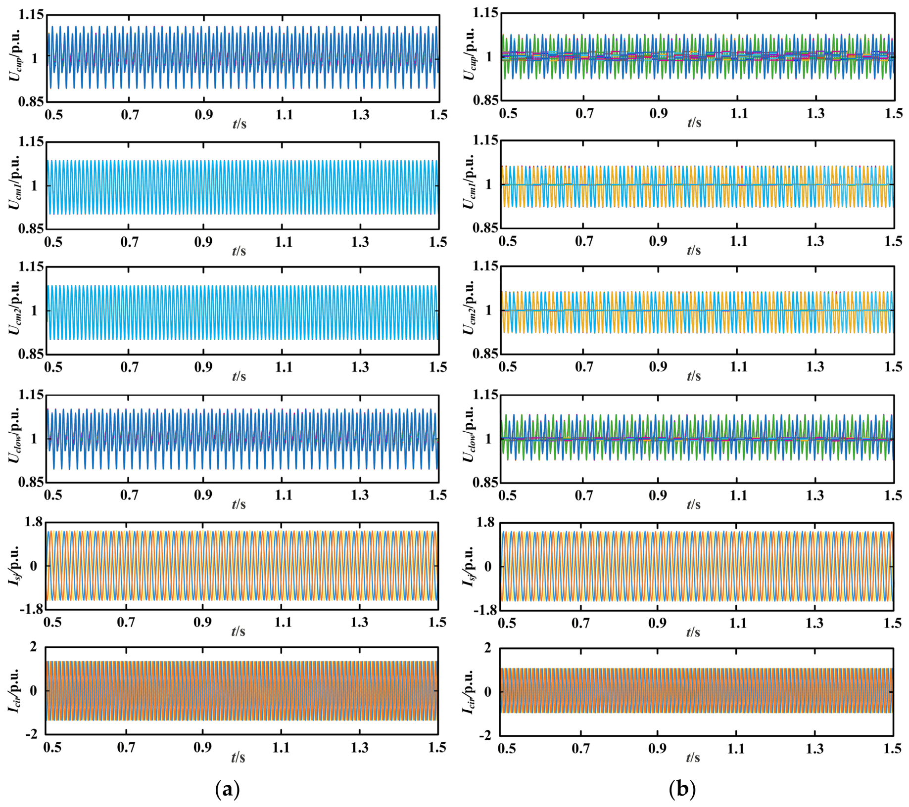
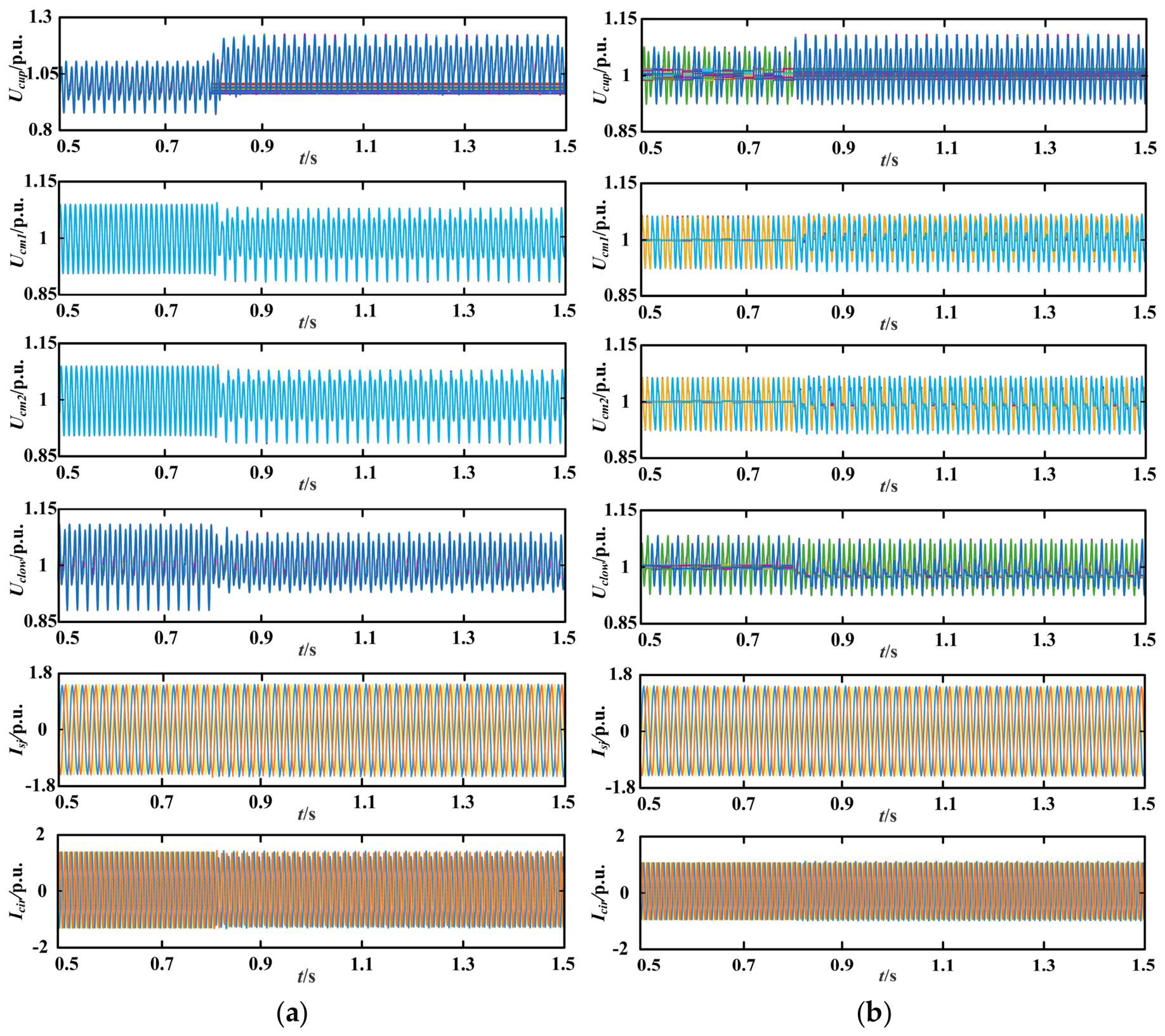
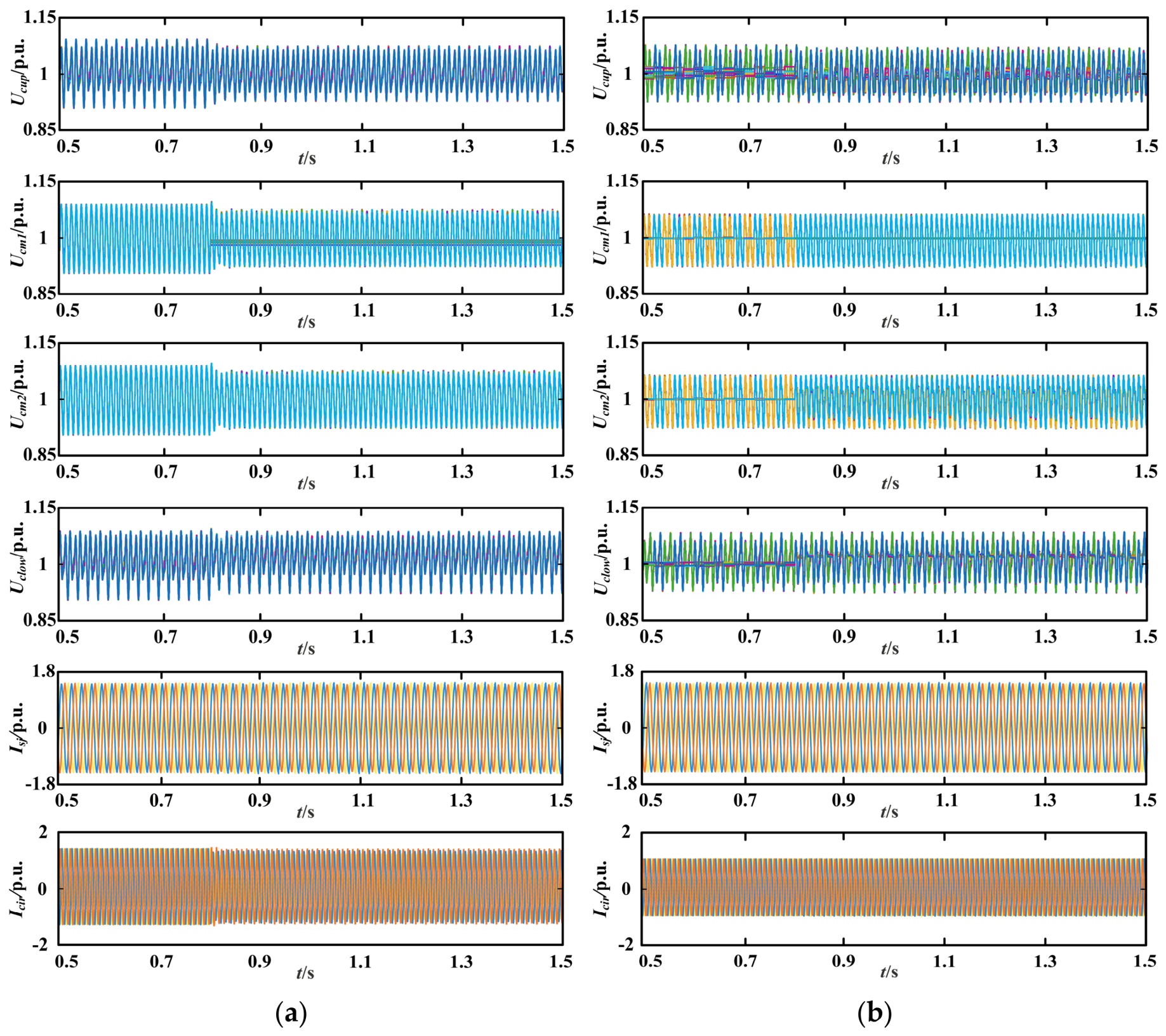
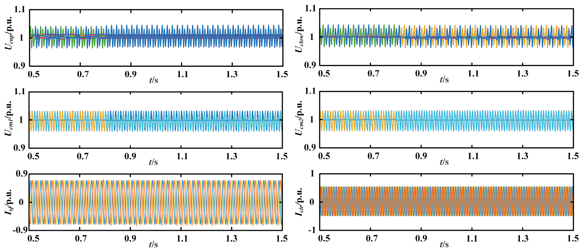
The defects of hot-standby SMs mainly occur in the normal operation stage. Thereby, the regulation for the hot-standby SMs in the fault-tolerant structure under normal operation of AM-MMCs is a key part of fault tolerance for AM-MMCs. In addition, enhancement of the fault-tolerance capability is also crucial. Thus, the proposed fault-tolerant control of AM-MMCs is presented in the normal operation and postfault operation.
4.1. Normal Operation of AM-MMCs with Fault-Tolerant Structure
In MMCs, the hot-standby SMs do not support the modulation. This indicates that the DC voltage is still undertaken by
N SMs of a phase leg at each moment, rather the total
N + 3
M SMs. Thus, the rated capacitor voltage of both MMCs and AM-MMCs is expressed as:
However, hot-standby SMs take part in modulation. For example, if
Non is equal to X, the NLM will select X SMs with proper capacitor voltages from
N + 3
M SMs to operate. Then, the standby SMs can also be inserted like the ordinary SMs. In order to focus on theoretical analysis, the transient processes for the turn-on and turn-off of the semiconductor devices are ignored and the IGBTs in SMs are regarded as ideal switches. Based on the above, the average switching function is changed as:
where
Nk denotes the total number of SMs in the equivalent arm.
k is equal to 1, 2 or 3. It is determined by the number of arms contained in the equivalent arm.
Due to the same insertion opportunity, the capacitor voltages in hot-standby SMs can be well charged as ordinary SMs, but the high similarity to ordinary SMs also imposes the same loss and fault risk to the standby SMs. Besides these, the circulating current will also increase under the operation mode. Although the selector switches adjust the multiplexing arms to operate together with the upper or lower arm, the equivalent arm voltages are still the superposition of the SM voltages contained in the arms. Thus, the equivalent arm model is immune to the selector switch transition effects. Combining the equivalent arm model, the circulating current can be calculated as:
where the subscripts
u and
l denote the equivalent upper arm and equivalent lower arm of an AM-MMC.
Uci is the capacitor voltage, which can be expressed by arm current
iarm as:
In high-voltage scenario, the AM-MMC contains plentiful SMs, but these SMs are in the same structure built by the same specification devices, and thus the SM parameters are identical. Furthermore, under the voltage-balancing algorithm, the capacitor voltages are well balanced and ripple around the rated value. Due to that, the capacitor voltages in the equivalent upper or lower arm can be deemed as equal. Then, (5) can be simplified as:
In (7), Non_u and Non_l are yielded by NLM and NLM and confirm these Non based on Urated. However, the actual inserted capacitor voltage is Ucxi in (6) rather than Urated in (3). Due to this deviation, icirj in (5) emerges. It is obvious that the AC component in Ucxi is larger, the deviation between Ucxi and Urated is larger, and icirj will be more serious. This AC component is related to Savg. If M is smaller in (4), the inserted opportunity is assigned to fewer SMs and each SM has higher possibility to change states. The more abundant state changes can make the capacitor voltage be more properly adjusted by iarm and the AC component can be reduced. Then, icirj will be also weakened.
Based on the above analysis, the following conclusions can be drawn:
If hot-standby SMs reduce the working duration in the arm, the operation loss and fault risk can be lowered.
If hot-standby SMs do not participate in modulation, the circulating current will be reduced.
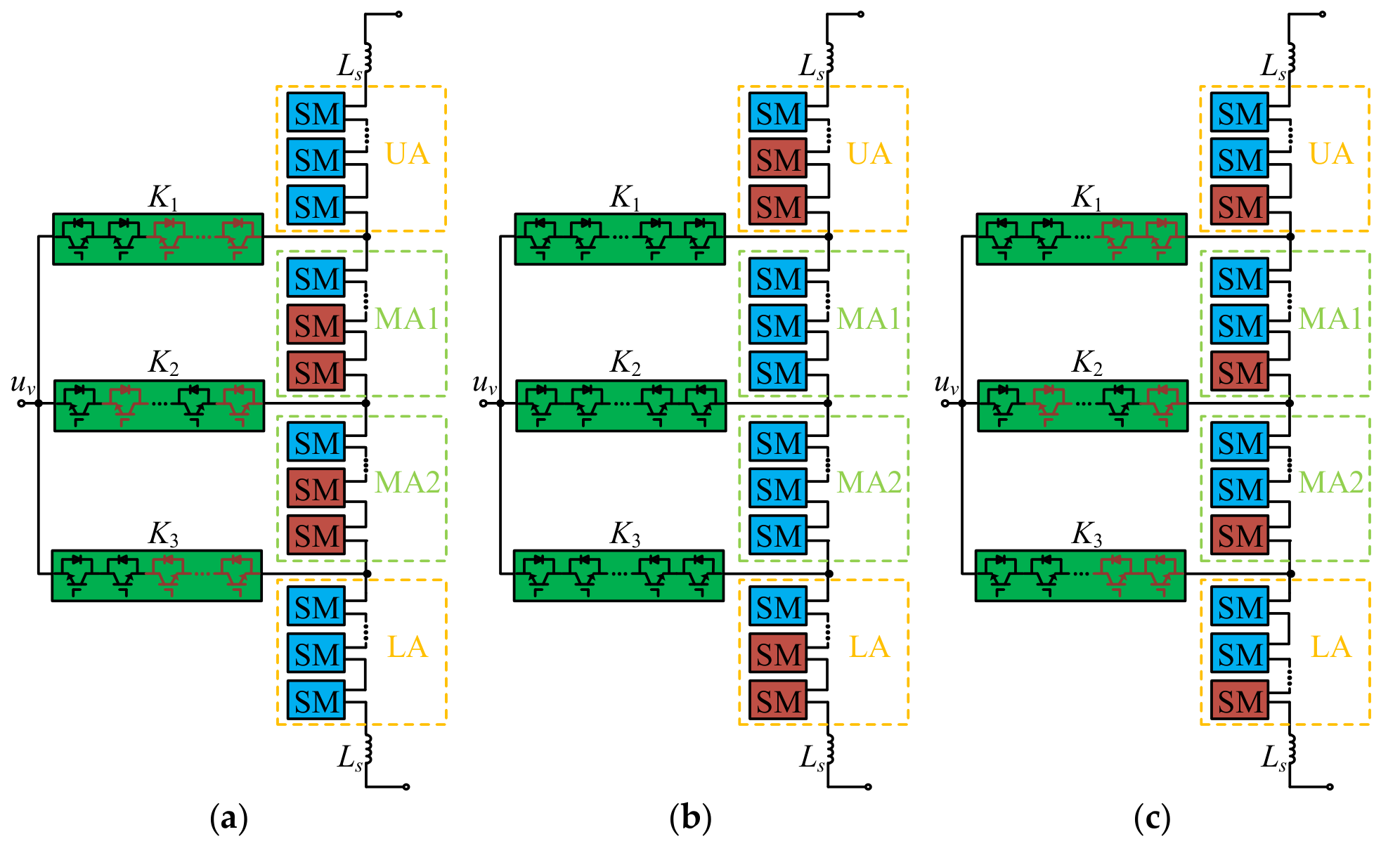
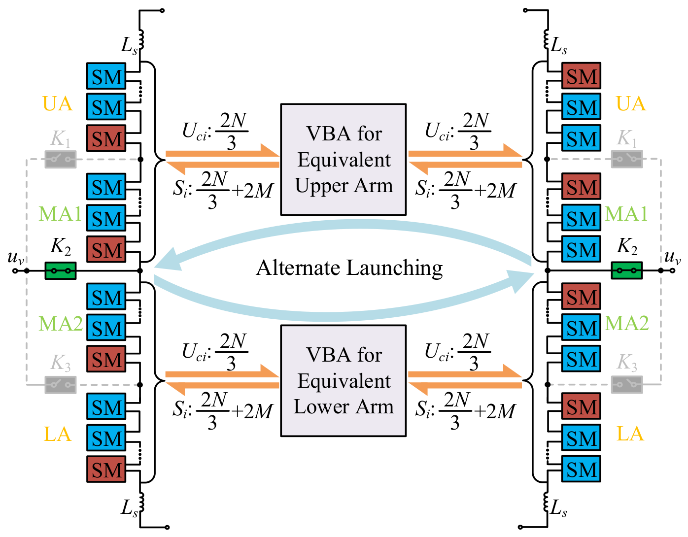
To realize the above, the alternate launching method is proposed. Firstly, only
Nk capacitor voltages are allowed and sent to the voltage-balancing algorithm (VBA). By that, the
Non inserted SMs can only be selected from
Nk SMs. The implementation method is that
kM standby SMs and the same number of ordinary SMs are alternately put into the
Nk SMs. Then, the number of the SMs participating in the modulation is kept as
Nk and
kM SMs are forbidden to join the modulation, which is equivalent to
kM in (4) equalling 0. Thus, the circulating current can be reduced. In addition, the alternate launching makes the standby SMs intermittently operate, which can ensure the lower loss and risk, and keep the capacitors in the standby SMs well charged. Therefore, the alternate launching method integrates the advantages of hot-standby and cold-standby SMs. The details are shown as
Figure 5.
In
Figure 5, the case of Mode 2 is used to express the alternate launching operation. To simplify the control, the alternate objects of the
M standby SMs in each arm are selected as the fixed SMs. Since the alternate operation can lower fault risk, the
M higher fault-prone ordinary SMs confirmed by the condition-monitoring algorithm can be employed as the alternate SMs. Although
M higher fault-prone ordinary SMs may distribute in the whole arm and are not serial, it is still easy to realize. That is because the condition-monitoring algorithm has confirmed
M SMs, and the
M standby SMs are usually the last successive
M SMs in an arm. These known SM messages will be sent to the control system. According to the SM settings, the proposed method will regulate these SMs to realize the alternate operation. In
Figure 5,
M higher fault-prone ordinary SMs are assumed as the first
M SMs in each arm. These SMs and standby SMs are alternated to incorporate to the capacitor voltage list. The alternate interval can be 1~
n line cycles. Then, always 2
N/3 capacitor voltages are sent to the VBA and 2
N/3 + 2
M switching signals are generated. Thus, 2M SMs do not join modulation and each arm has no extra loss. Meanwhile, the standby SMs are also well charged.
As shown in
Figure 5, the SMs taking part in the alternate launching will stay in the bypassing state and operating state alternatively for a certain interval. As previously mentioned, the alternate interval is the crucial parameter of the proposed alternate launching and can be
k times the line cycle, where
k is an integer. Therefore, the two states will respectively continue
k line cycles. When the capacitor voltages are in the operating state, they can balance with the capacitor voltages in the ordinary SMs that are not involved in the alternate launching. Since the bleeding resistor is connected in parallel with the capacitor in the SM, the capacitor voltage will degrade during the bypassing state if the alternate interval is too long. When the alternate interval is properly selected, the capacitor voltage values are equal or only have little deviation at the terminals of the bypassing state interval. It is the basic to maintain the capacitor voltage balancing. Furthermore, the capacitor voltages in ordinary SMs that do not join the alternate launching are periodical components and fluctuate periodically. Then, they can also be almost equal with each other at the terminals of the bypassing state interval. Moreover, the beginning of the bypassing state interval is the ending of the operating state interval. As previously mentioned, all the capacitor voltages are balanced in the operating state interval. Combining the above, the voltage balancing can be well maintained when the capacitor voltages finish bypassing states to enter operating states again. This indicates that the alternate launching has no influence on the capacitor voltage balancing if the alternate interval is properly selected. It is worth noting that capacitor voltages belonging to the bypassing state in the alternate launching will exhibit a relatively large deviation with other capacitor voltages. This deviation has no influence on the operation, since these bypassed SMs are excluded and do not join the modulation.
Differently from the capacitor voltage balancing, the switching losses are not affected by the alternate interval. Compared with the conventional standby method, the standby SMs are no different from the ordinary SMs. Therefore, the extra switching losses in the standby SMs will be yielded, i.e., a total of Nr + M times Ploss exist. Nr denotes the number of SMs in a single arm of an AM-MMC. Ploss means the switching losses of a single SM. The alternate launching method can make M standby SMs and M ordinary SMs alternatively operate. When the M standby SMs are in operating state and the selected M ordinary SMs are in the bypassing state, the standby SMs generate switching losses and the ordinary SMs have no switching losses, and vice versa. In essence, M times Ploss are allocated to the 2M SMs, and the total loss is reduced. Compared with the conventional method, the total switching losses decrease to Nr times Ploss under the proposed alternate launching method. However, regardless of the duration of the alternate interval, always Nr SMs take part in the modulation. Thus, the alternate interval has no influence on the total switching losses.
Thus, the alternate interval can be selected based on the capacitance, the bleeding resistance and the allowed range of the capacitor voltage fluctuation. In general, several line cycles will not cause serious degradations in capacitor voltages. After the alternate interval is selected, the alternate launching method can be easily realized in the control system. The condition-monitoring algorithm has confirmed the ordinary SMs to alternatively exchange states with the standby SMs. Therefore, it is sufficient that the values in the capacitor voltage sorting of the voltage-balancing algorithm update along with the specified capacitor voltages with the alternate interval. Compared with the conventional method, the data quantity in the voltage-balancing algorithm is reduced from Nk + kM to Nk under the alternate launching method, which can lower the burden of the control system. Besides these, no extra change is needed, and thus the control complexity does not rise.
4.2. Fault-Tolerant Operation of AM-MMCs
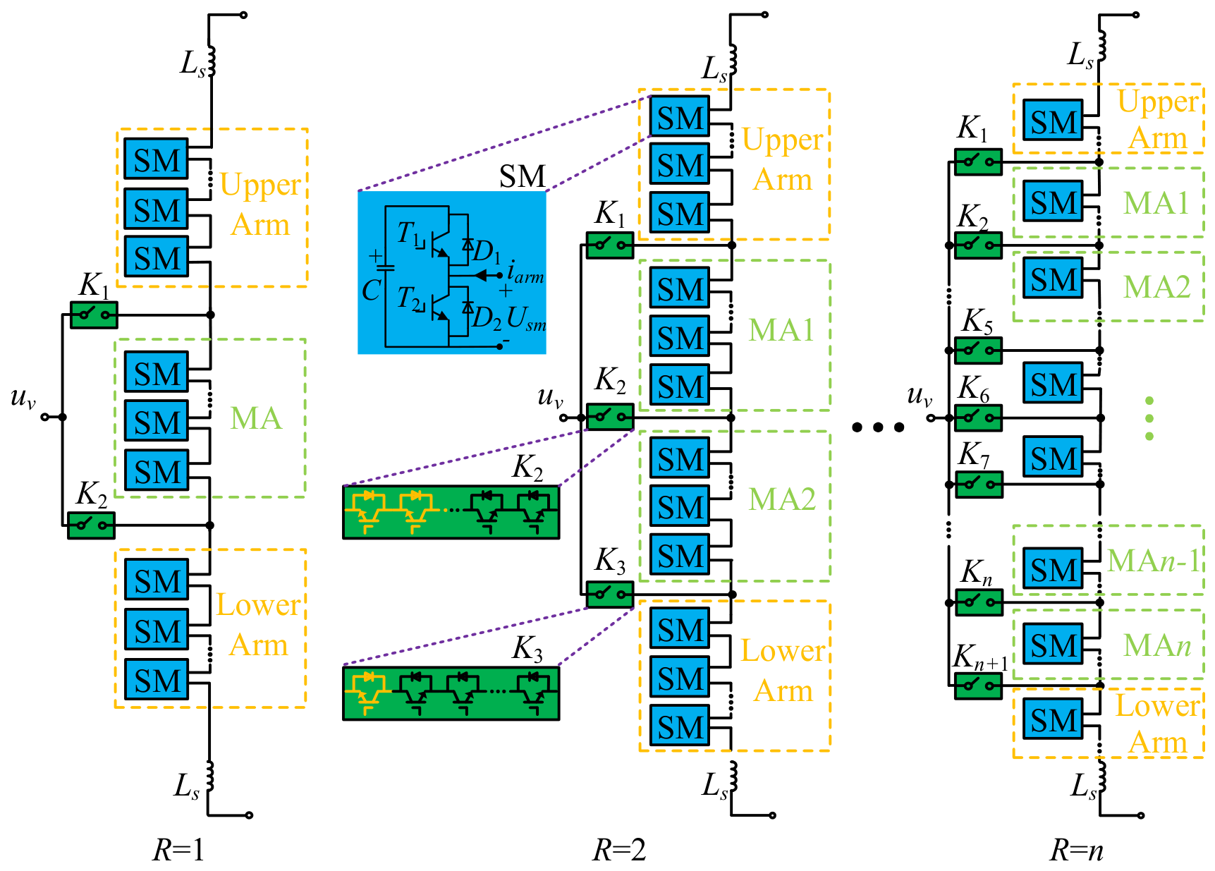
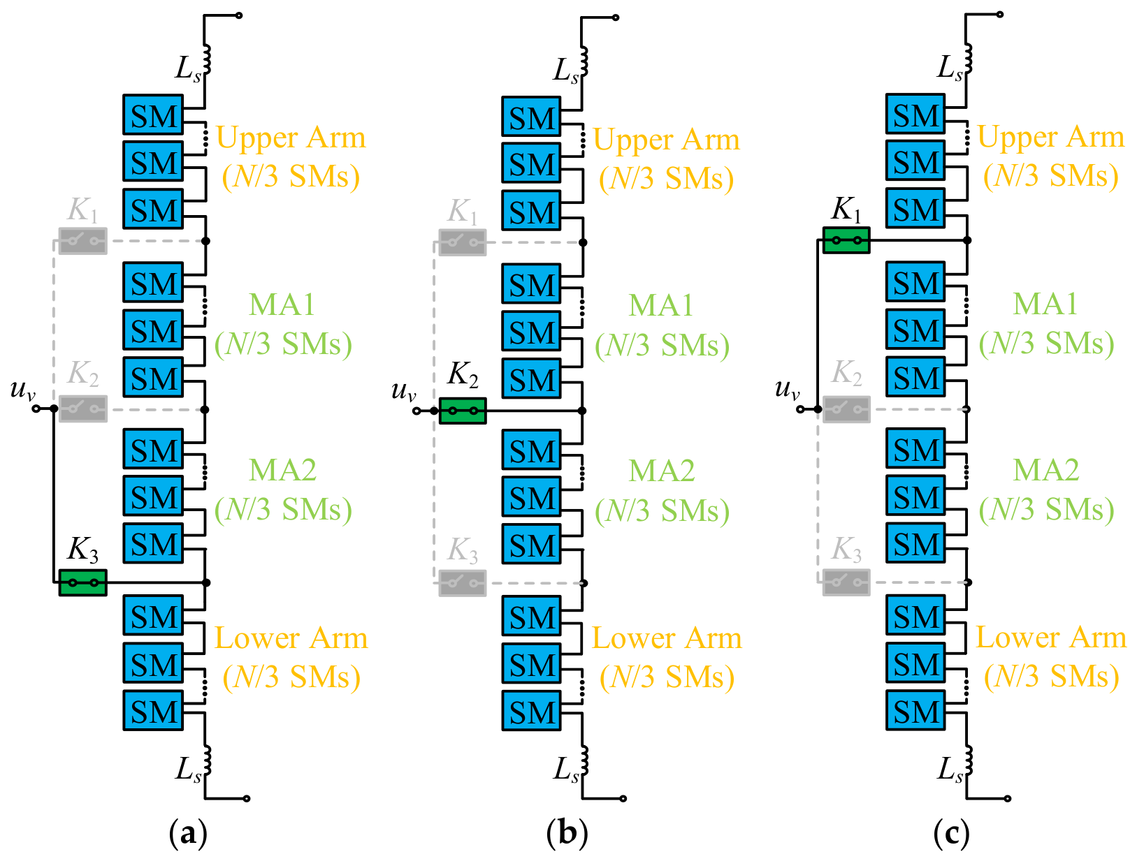
Although Type 3 has the same fault-tolerant capability as MMCs, the stronger fault-tolerant capability means stronger reliability of AM-MMCs. With the accessing of the multiplexing arms, the largest fault-tolerant number of an equivalent arm is changed and is in the range M~3M. For example, the equivalent upper arm can tolerate 0~M faults when it consists of the single upper arm, 0~2M faults when it consists of the upper arm and a multiplexing arm, and 0~3M faults when it consists of the upper arm and two multiplexing arms. If the faults distribute evenly in multiple arms, at most 3M simultaneous faults can be tolerated, such as M faults respectively occurring in the upper arm, MA1 and MA2, even though, to ensure the overall reliability, the equivalent upper arm can tolerate at most M faulty SMs since the standby SMs in multiplexing arms cannot help to cope with extra faults when the upper arm operate solely with more than M faulty SMs. Obviously, much of the fault-tolerant potential is wasted and the total fault-tolerance capability is determined by the largest fault quantity that a single arm can handle. Due to this, the switching moment reset-based fault-tolerant control is developed. Under this method, the operation reliability can be well maintained when 3M faults simultaneously occur in a single arm. With this capability, the feasible fault-tolerant boundary of the equivalent arm is enhanced to 3M. Moreover, regardless of which arm the fault is located in, the equivalent upper or lower arm can at most tolerate 3M faults. Since the conditions of the upper arm and MA1 are respectively the same for the lower arm and MA2, the fault conditions of the upper arm and MA1 are analyzed in detail.
If 3
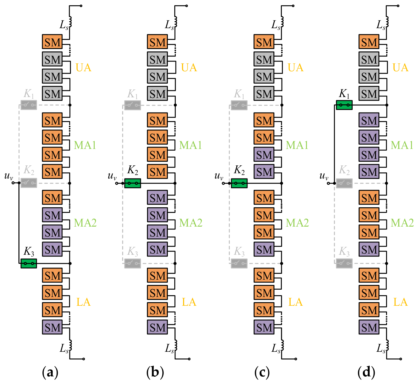
M SMs in the upper arm malfunction, the operation is shown in
Figure 6, where the SMs in gray, in orange and in purple represent faulty SMs, operating SMs and leisure SMs, respectively. Since standby SMs are usually inactive, they are also purple in color. As shown in
Figure 6a, the SMs are adequate in Mode 1 before switching to Mode 2. Even if the modulation requires all the ordinary SMs in the three arms to operate, the 3
M standby SMs in UA, MA1 and MA2 can completely supplement the lacking SMs in Mode 1. According to the modulation rule introduced in
Section 2, Mode 1 will switch to Mode 2 at the moment that
Non of the equivalent upper arm equals 2
N/3. When switching to Mode 2, shown in
Figure 6b, the reduced
N/3 SMs and the missing 3
M faulty SMs make the equivalent upper arm unable to meet modulation. Compared with
Figure 6a,
M SMs are lacking in
Figure 6b, since only 2
M standby SMs are available in Mode 2. The pre- and post-switching from Mode 2 to Mode 3 are shown in
Figure 6c,d. A similar case occurs around the switching moment. Importantly, while switching to Mode 3, 2
M SMs are lacking in the equivalent upper arm in
Figure 6d, compared with
Figure 6c.
If 3
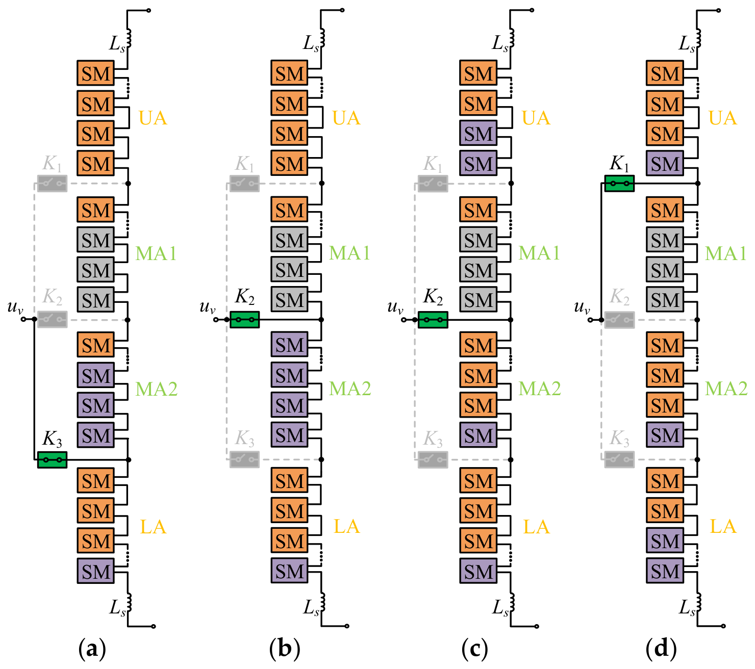
M SMs in the MA1 malfunction, the operation is shown in
Figure 7. As shown in
Figure 7a, 3
M standby SMs in the equivalent upper arm can also the ensure the high-quality operation of an AM-MMC after faults. When Mode 1 switches to Mode 2, the fault-tolerant support changes from 3
M standby SMs to 2
M standby SMs. Accordingly, at the initial operation stage of Mode 2 in
Figure 7b, the fault-tolerance measure cannot fully recover the postfault operation to normal level. As shown in
Figure 7c, with the reduction in required SMs in the latter operation stage of Mode 2, the faults will not affect the operation of the equivalent upper arm. Moreover, at the moment that Mode 2 has switched to Mode 3, MA1 belongs to the equivalent lower arm and the 3
M standby SMs can be provided again.
Based on the above analysis, the conventional fault-tolerance measure cannot handle the operation period around the mode switching. Then, the switching moment reset-based fault-tolerant control is presented in
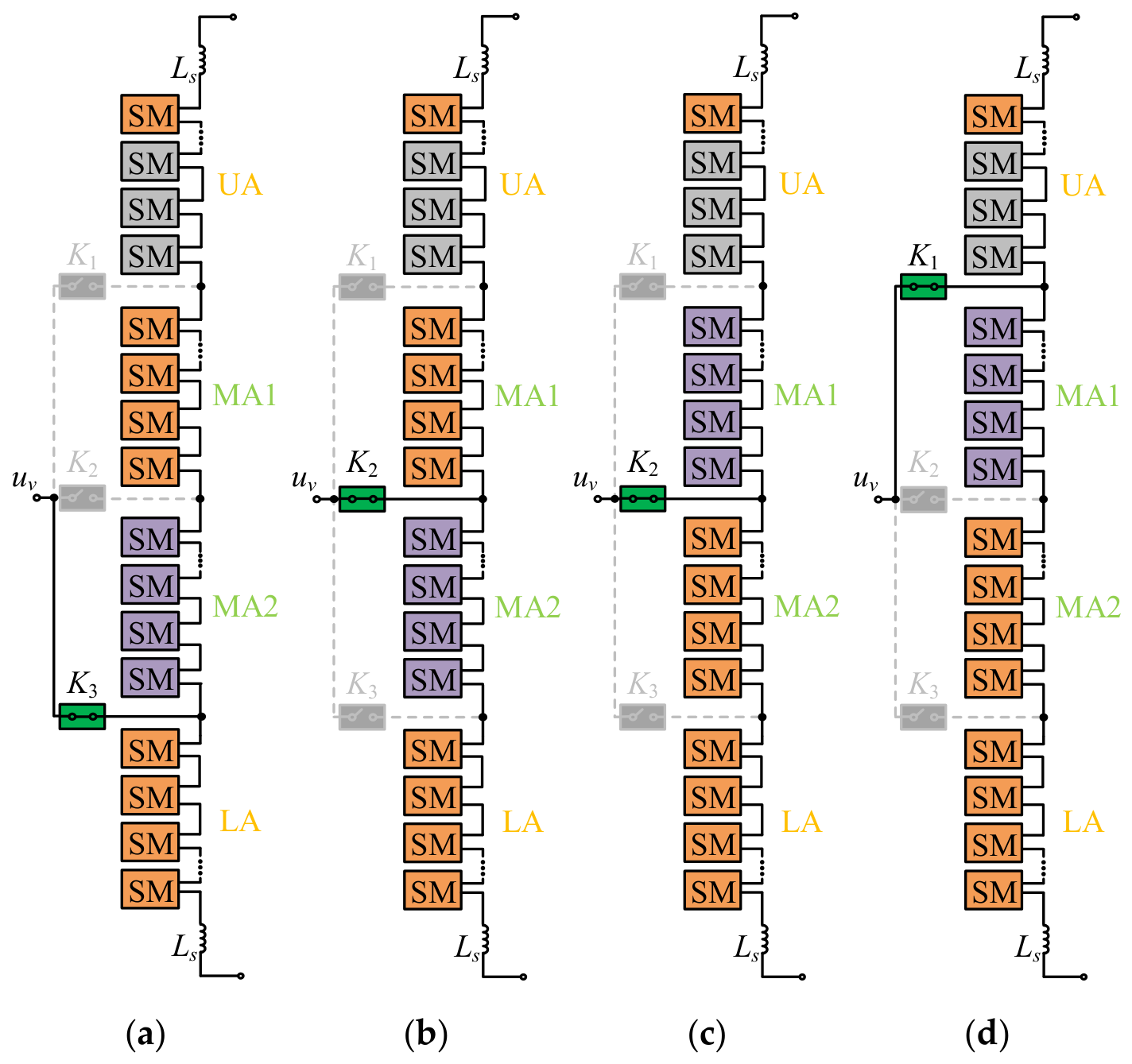
Figure 8. As shown in
Figure 8a, the switching moment from Mode 1 to Mode 2 is delayed until the
Non of the equivalent upper arm is 2
N/3 −
M, rather than 2
N/3 in
Figure 6a. Thus, the equivalent upper arm does not lack SMs in
Figure 8b. It is crucial that the standby SMs in the equivalent lower arm will be launched when the switching moment is reset. As shown in
Figure 8c, the switching moment from Mode 2 to Mode 3 is changed at the moment that the
Non of the equivalent upper arm equals
N/3 − 2
M, instead of
N/3 in
Figure 6c. Then, the equivalent upper arm in
Figure 8d also has enough SMs and no abnormality occurs.
As shown in
Figure 7, the main defect occurs around the switching from Mode 1 to Mode 2, namely the initial operation stage of Mode 2. It can also be resolved by the switching moment reset method. The specific reset switching moments for the two types of faults are listed in
Table 4, where M1, M2 and M3 are short for Mode 1, Mode 2 and Mode 3.
With the switching moments marked by the inserted SM numbers shown in
Table 4, each arm in the AM-MMC with Type 3 can tolerate 3
M faulty SMs. Compared with
Table 3, the fault-tolerant capability is effectively enhanced, identically to Type 2. In
Table 4, the fault-tolerant cases for the largest fault quantity are shown. To be more general, the switching moment for the other fault quantity can be derived as follows. When the fault quantity
h in a single arm lies in [0,
M], the switching moments do not need to be reset, because the standby SMs in each arm are sufficient to handle these faults. When
h lies in [
M, 3
M], the switching moment reset is necessary since all the
h faults may occur in the same arm. If the arm operates solely, the faults cannot be fully handled by the standby SMs in this arm and the other standby SMs cannot be available. Therefore, when the fault quantity is identical, the case in which faults occur in the same arm is more serious than the case in which faults occur in multiple arms. If the most serious case can be well handled, the operation can also be maintained under other fault cases. Thus, similarly to
Table 4, the cases in which all the faults occur in the upper arm and MA1 are discussed.
With the confirmed fault case, the switching moment can be formulated as the function of the actual fault quantity
h. The SM quantity at the conventional switching moment is denoted as
Nh. In the operation mode that is going to be switched to, the standby SM quantity of the equivalent arm that contains the faulty arm are assumed as
Mh. If
h is less than
Mh, the switching moment does not need to be reset. Otherwise, the switching moment should be reset as
Nh +
Mh-
h. Combining this expression, operation mode and fault message, the specific switching moment can be derived. For example, if the
h faults occur in MA1 and M1 is going to switch to M2, the specific switching moment is derived as follows. According to the operation principle of the AM-MMC,
Nh can be confirmed as 2
N/3 and the equivalent arm that contains the fault (MA1) is the equivalent upper arm, which is composed of an MA and the upper arm. Thus,
Mh is 2
M. Then, the switching moment is changed from 2
N/3 to 2
N/3 + 2
M-
h. If
h is equal to 3
M, the reset switching moment is consistent with the value listed in
Table 4.
In essence, the SM margin can ensure that the equivalent lower arm continues to operate when the conventional switching moment has come. Furthermore, the SM margin offered by the equivalent lower arm equals the SM vacancy by which the faulty SMs exceed the standby SMs in the equivalent upper arm after switching. After the multiplexing arm is removed, the remaining SMs in the equivalent upper arm can also meet the requirement and the SM lacking under conventional method is avoided. Moreover, combining the commutation process analysis in the normal operation, it can be easily derived that the equivalent upper and lower arms with the reset switching moments can also rigorously meet the SM quantity requirement without the participation of the multiplexing arm at the commutation moment. Thus, the multiplexing arm can be temporarily bypassed and the introduced two commutation measures can also be implemented under the switching moment reset method. Then, the selector switches can reliably commutate under the same proposed switching moment reset method as that of normal operation. Furthermore, smooth arm switching can be realized and the premium fault-tolerant operation can be ensured.