Article

Mechanically Reconfigurable Dielectric Transmitarray for Dual-Beam Communications

by
Francesco Alessio Dicandia
1,* and
Simone Genovesi
2
1
CNR-Istituto di Elettronica e di Ingegneria dell’Informazione e delle Telecomunicazioni, 56122 Pisa, Italy
2
Dipartimento di Ingegneria dell’Informazione, University of Pisa, 56122 Pisa, Italy
*
Author to whom correspondence should be addressed.
Electronics 2026, 15(14), 3144; https://doi.org/10.3390/electronics15143144
Submission received: 24 June 2026 / Revised: 10 July 2026 / Accepted: 14 July 2026 / Published: 16 July 2026
(This article belongs to the Special Issue New Challenges in Beyond 5G/6G Network Wireless Technologies)

Abstract

A mechanically reconfigurable transmitarray (TA) to support point-to-multipoint (PtM) communications via simultaneous dual-beam radiation is presented. The architecture employs two independently rotating flat dielectric TAs whose transmitting element permittivity values are rigorously synthesized to transform the feeder spherical wavefront into concurrent multiple beams, thereby enabling simultaneous dual-beam scanning in both elevation and azimuth. The numerical analysis and full-wave simulations demonstrate that the proposed design strategy can achieve a maximum dual-beam elevation scan of 55° with a 3 dB dual-beam gain bandwidth larger than 18%. A prototype comprising two flat dielectric TAs operating at 35 GHz and producing a mechanically scanned dual-beam has been manufactured using an additive manufacturing process. The measurements are in good agreement with the expected outcomes and confirm the effectiveness of the proposed synthesis strategy.

1. Introduction

Transmitarray (TA) antennas are capable of manipulating and tailoring the electromagnetic wavefront radiated by a feeder and they are expected to play a key role in many of the emerging wireless communications systems thanks to their versatility [1,2,3,4]. While high-gain single-beam scanning antennas [5] have proven effective in past and current systems, the shift towards 6G networks will increasingly require concurrent multi-beam radiation systems with beam-steering capability to support the development of emerging wireless services [6,7]. Indeed, point-to-multipoint (PtM) communications via simultaneous multi-beam (SMB) transmission can enhance coverage and throughput, enabling multicast wireless communications as well as supporting group-oriented wireless services [8]. Moreover, these features could be particularly beneficial for future space–air–ground integrated networks (SAGINs) and could be pivotal in disaster-management scenarios [9,10,11]. In the context of TA, steerable SMB radiation has only been achieved in [12], where an analytical multifocal scheme, enhanced with a modified minimum mean square error, allows efficient mechanically steerable SMB in a principal plane. Other TA solutions, on the contrary, offer SMB in fixed directions [13,14,15,16,17,18,19] with no option to scan the multiple beams. For example, a single-feed multi-beam TA enabled by cascaded anisotropic impedance surfaces has been proposed in [13]. In ref. [15], a particle swarm optimization approach for synthesizing a single-feed quad-beam TA has been presented. In ref. [19], an innovative synthesis approach for realizing a single-feed, simultaneous multi-beam, fully dielectric TA with both phase and amplitude control at the unit cell level has been presented.
The purpose of this work is to propose a novel mechanically reconfigurable TA to support PtM communications via dual-beam scanning. The architecture comprises two independently rotating planar dielectric TAs whose unit cell permittivity values are rigorously synthesized to transform the feeder spherical wavefront into multiple concurrent beams, thereby enabling an efficient steerable dual beam in both elevation and azimuth. It is worth noting that although several mechanically scanning antennas based on rotatable surfaces, also known as Risley prism antennas, have been proposed with diverse radiation characteristics, they have been limited to a single steerable beam [20,21,22,23]. Although dual circularly polarized 2D beam scanning has recently been achieved using a folded reflectarray [24], as far as the authors are aware, no mechanically reconfigurable dielectric TA has demonstrated steerable SMB in both elevation and azimuth.
The paper is organized as follows. Section 2 describes the methodology for synthesizing a 2D mechanical-steering SMB by resorting to the proposed TA scheme and an analytical procedure for synthesizing and estimating the radiative performance of the overall structure based on a cascade of multiple transmission lines. The following section, Section 3, is devoted to the full-wave-simulation radiative performance assessment. The fabrication of a fully dielectric mechanically scanning TA by means of 3D printing technology and the experimental results are illustrated in Section 4, whereas Section 5 provides the conclusions.

2. Mechanical Reconfigurable TA Design with SMB Radiation

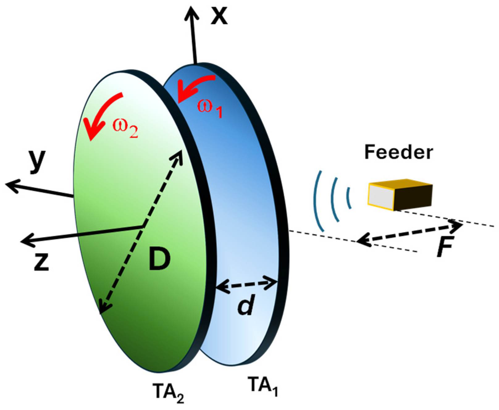
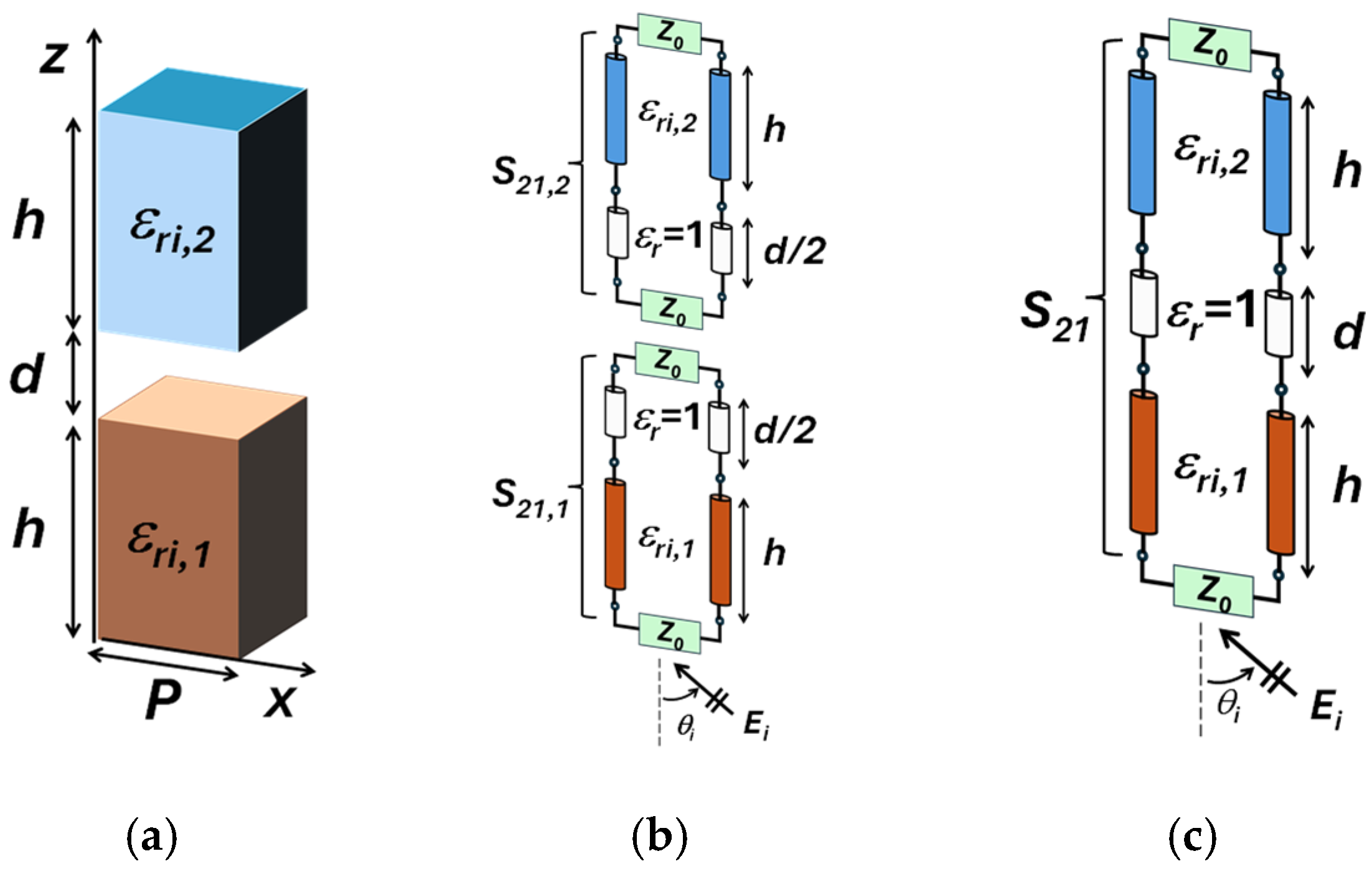
The considered mechanically reconfigurable TA configuration, shown in Figure 1, relies on a cascade of two rotatable fully dielectric TAs (i.e., TA1 and TA2). The transmitting unit cells are placed on a square lattice of period P = 0.5 λ00 is the wavelength at the considered working frequency of 35 GHz) and are illuminated by a spherical wave emitted by a feeder at (0,0,−F), where F is the focal distance. The proposed wavefront manipulation methodology is based on the equivalent transmission line model (TLM) of each unit cell, enabling rapid synthesis and radiative performance estimation. Each dielectric unit cell is modelled as a cascade of transmission line segments with a predefined thickness h, spacing d and an unknown permittivity (Figure 2a).
The thickness of each dielectric TA (h) mainly depends on the required maximum phase shift and the difference between the maximum and minimum available permittivity, according to the following equation:
h k 2 π ε r , m a x k 0 2 k t 2 ε r , m i n k 0 2 k t 2         k 0 = 2 π λ 0 ;   k t = k 0 s i n θ i
where εr,max and εr,min represent the maximum and minimum permittivity that each unit cell can assume, kt is the transverse wave vector, and k [0, 1] is a number that affects the maximum phase variation (i.e., k2π) of a dielectric line. As the denominator of (1) reaches a minimum value for normal incidence (θi = 0°), the dielectric thickness of the TA is given by:
h k ε r , m a x ε r , m i n λ 0
For the i-th unit cell, the pair of permittivity values (εri,1 and εri,2) is obtained through a synthesis procedure based on two TLMs (Figure 2b) terminated in the free space impedance, Z0, in order to manipulate the impinging electric field coming from an angle of incidence θi and passing through the cells.
The target complex transmissions are prescribed as follows:
S 21,1 = a = 1 A e j β x sin θ 1 a e j β r i f x , y
S 21,2 = e j β x sin θ 2 e j β r i 1 f x , y
f x , y = 0.5 x 2 + y 2 D / 2 2.5 + 0.5
where S21,1 and S21,2 represent the complex transmission coefficient of the two equivalent TLMs of Figure 2b, β = 2π/λ0 is the wave number, (x,y) and r i = x 2 + y 2 + F 2 are the geometrical coordinates of the i-th unit cell and its distance with respect to the feeder, θ1a represents the A main lobe peak directions of TA1, and θ2 adjusts the additional phase gradient of TA2. The function f(x,y), which goes from zero to one, controls the compensation ratio of the incoming spherical wave between the two TA apertures. The main peak directions of the SMB and the rotation angles of the two TA layers are linked by the following equation:
M B b = s i n θ 1 a e j ω 1 + s i n θ 2 e j ω 2
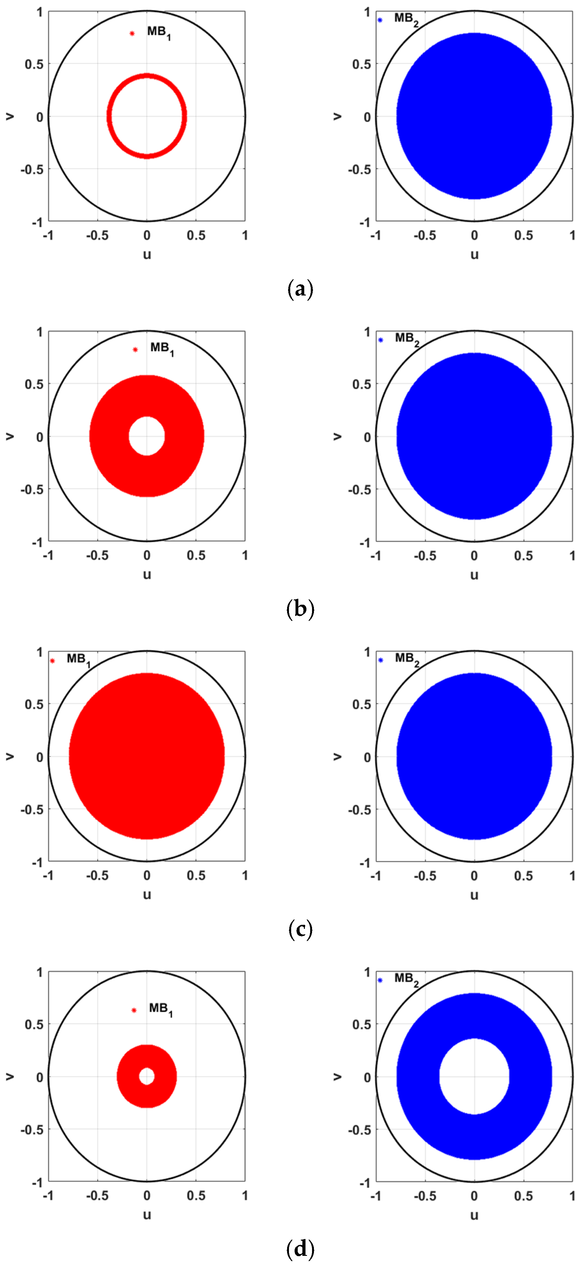
where ub = real(MBb) and vb = imag(MBb) stands for the main peak directions in the uv space. To demonstrate the flexibility and versatility of the proposed synthesis approach in terms of beam coverage, the pointing directions are evaluated through a multi-beam configuration featuring two simultaneous main beams (A = 2). Figure 3 highlights the beams’ pointing directions in the uv plane in the case of two concurrent main peaks with a maximum scan angle of θ0_max = 50°. These regions are obtained by plotting the directions of the main peaks for all possible pairs of TA rotation angles (i.e., ω1 and ω2) with a step size of 1°. In particular, the dual-beam coverage can be flexibly adapted to meet specific application requirements by modifying the wavefront manipulation through (3) and (4), by adjusting the angles θ1a and θ2. Such capability provides an additional degree of freedom in the synthesis process, which can be particularly beneficial for UAV networks as well as terrestrial and non-terrestrial systems [9].
To accurately characterize the radiative performance, the calculation of the transmission matrix (ABCD) for each layer has been performed by considering the field radiated by the feeder as a plane wave impinging on the unit cells with a certain amplitude, phase and incidence angle (θi). Once the permittivity values of both the layers are known, the ABCD matrix formalism for the full stack has been exploited for estimating the transmission coefficient (S21) in both magnitude and phase, as illustrated in Figure 2c.

3. Full-Wave Results

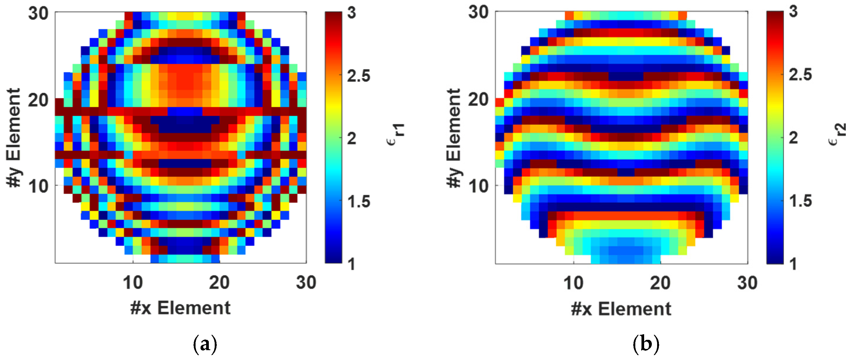
The radiative performance of a mechanically steerable TA multi-beam illuminated by an open-ended WR28 waveguide with an F/D value of 0.5 has been considered. Without loss of generality, the radiative performance assessment of the proposed method has been highlighted by considering multi-beam configurations with two simultaneous main beams (A = 2). Specifically, with the aim of providing a maximum beam scanning of θ0_max = 50°, the considered SMB directions of TA1 are θ11 = 0° and θ12 = sin−1[sin(θ0_max)/2]°), whereas the deflection angle for TA2 is fixed to θ2 = sin−1[sin(θ0_max)/2]°. Figure 4 shows the synthesized dielectric permittivity profile for both the TAs operating at f = 35 GHz with a permittivity range from one to three, thickness h = 9.36 mm and diameter of the circular TA of D = 15 λ0 (128.6 mm).
To assess the reliability of the proposed mechanical scanning TA and investigate its robustness, the synthesized fully dielectric panels were verified using full-wave electromagnetic simulations in CST Microwave Studio 2025 [25]. Specifically, the optimized dielectric layers have been implemented through different homogeneous dielectric brick elements and are illuminated by an open-ended WR28 waveguide. The scanning behaviour in a principal plane (ϕ = 0°) at f = 35 GHz as a function of the θ angle is shown in Figure 5.
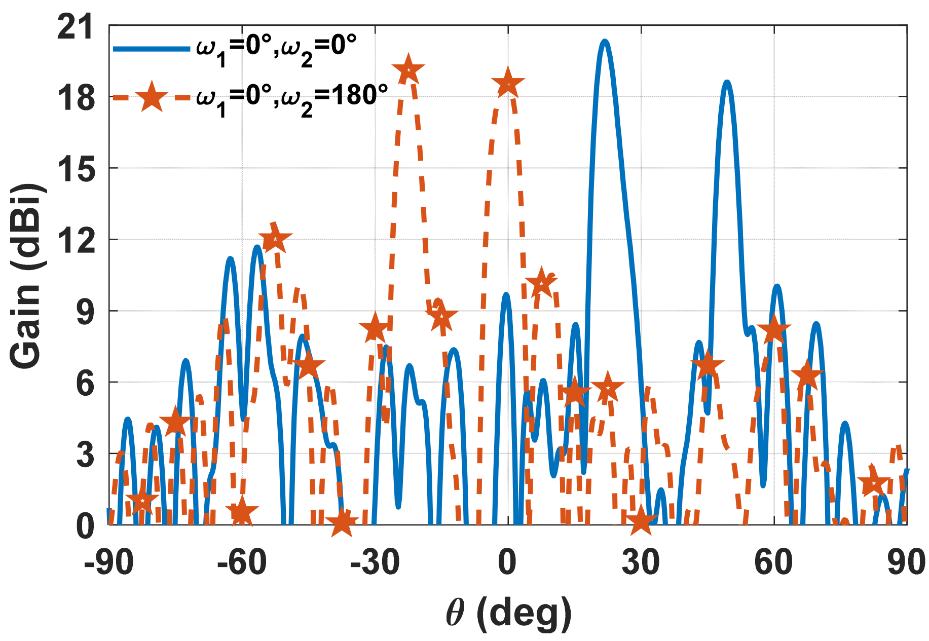
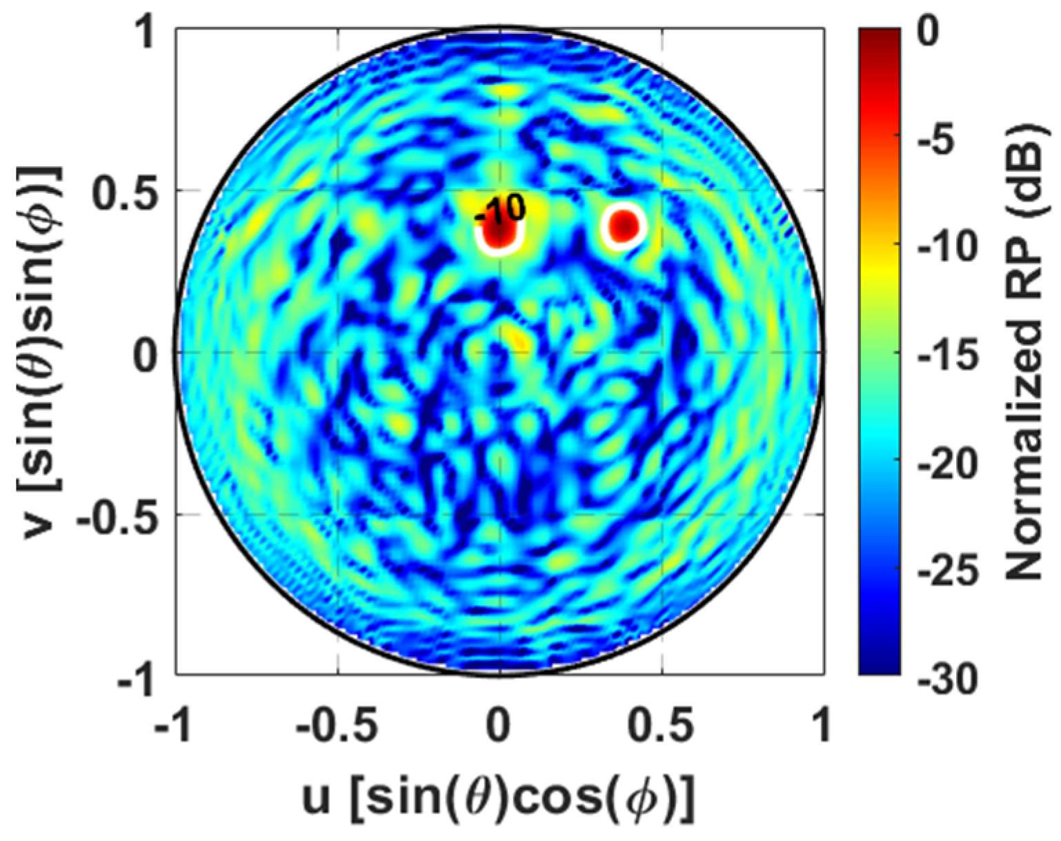
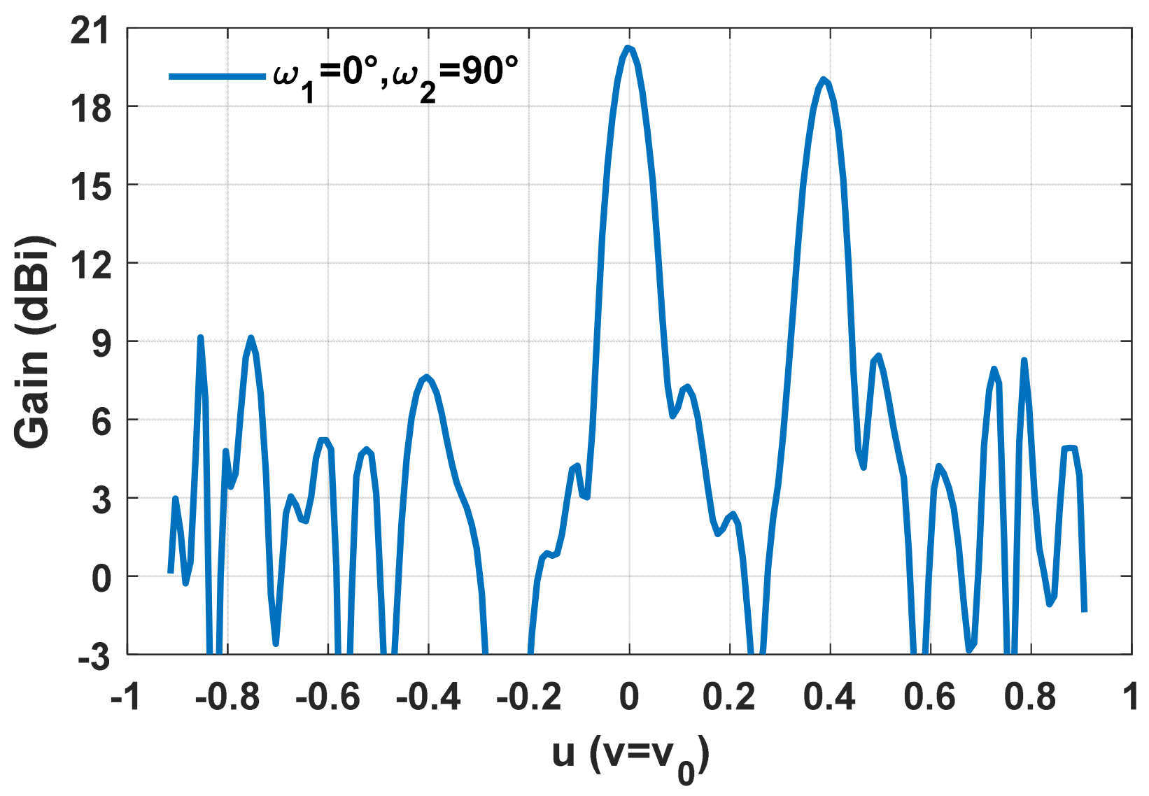
The gain values of around 18.5 dBi and 20.2 dBi are obtained at the desired directions θ1 = 50° and θ2 = 21.5°, respectively, with a peak sidelobe level (PSLL) of around −9 dB. Upon rotating TA2 by 180°, the SMBs are steered at θ1 = 0° and θ2 = −22.5° with gain values of 18.6 dBi and 19.1 dBi, respectively, whereas the simulated PSLL turns out to be around −7.5 dB. The simulated radiation pattern (RP) when the dual-beam radiation is outside the principal planes is reported in Figure 6 and Figure 7. The colour map of Figure 6 displays the normalized RP over the visible region in more detail, whereas the dual-beam gain pattern as a function of u for v = v0 = 0.38 is reported in Figure 7. Even in this case, a significant suppression of lateral lobes in the visible region is easily visible. Specifically, the full-wave simulation offers dual-beam gain values of 20.2 dBi and 18.9 dBi with a PSLL of −11 dB.
It is worth noting that, although the PSLL is found to be around −7.5 dB when the dual-beam radiation lies in the principal planes, it remains below −10 dB for the other 2D mechanical scanning configurations, resulting in an average PSLL of around −10.5 dB.
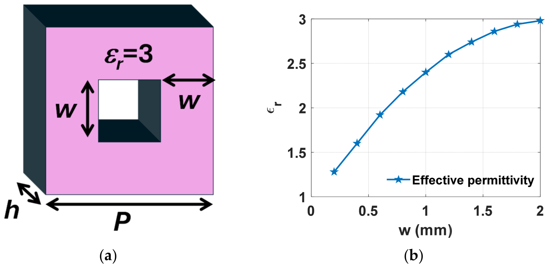
Finally, performance has been evaluated by using perforated dielectric unit cells to obtain the optimized value of permittivity for each unit cell (Figure 8a), thus providing a good matching with those achieved by the homogenized model. By locally modulating the volume ratio between air and dielectric host material, it is possible to achieve an effective permittivity that spans from one up to the intrinsic permittivity of the base medium (i.e., εr = 3), thereby enabling a spatially controlled phase term of each unit cell [26]. Figure 8b highlights the calculated effective permittivity of the perforated unit cell at 35 GHz as a function of the dielectric wall width (w) when P = 4.29 mm.
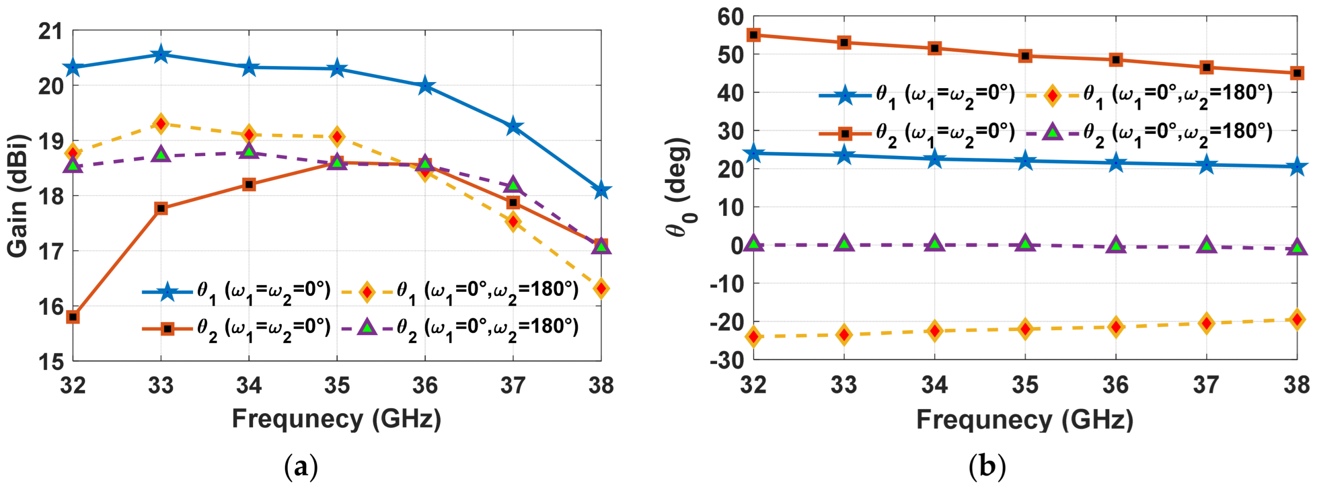
The frequency behaviour of the maximum dual-beam gain values was examined over the 32–38 GHz frequency range and is depicted in Figure 9.
The maximum dual-beam gain values occur around the frequency adopted for mechanical scanning aperture phase synthesis (i.e., f = 35 GHz). The SMB gain values related to the dual beam gradually decrease (Figure 9a), moving away from the selected f, although a 3 dB gain bandwidth greater than 18% is still achieved. As expected, the SMB pointing directions are not fixed within the frequency range (Figure 9b), but the pointing direction deviates less than 10% around the central frequency with the maximum dual-beam elevation scan of 55° occurring at 32 GHz.

4. Prototype and Measurement

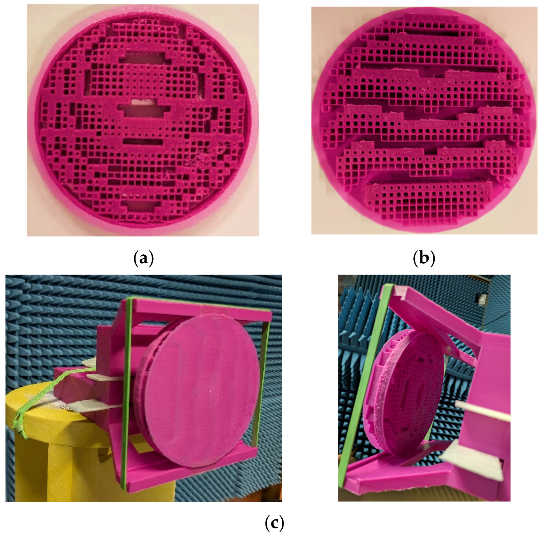
A mechanical scanning TA prototype providing dual-beam radiation and operating at 35 GHz has been manufactured through 3D printing technology and some pictures are reported in Figure 10. The dielectric TA has been realized by PLA filament, characterized by a dielectric constant and loss tangent around 3 and 0.01, respectively, via the fused deposition modelling (FDM) process.
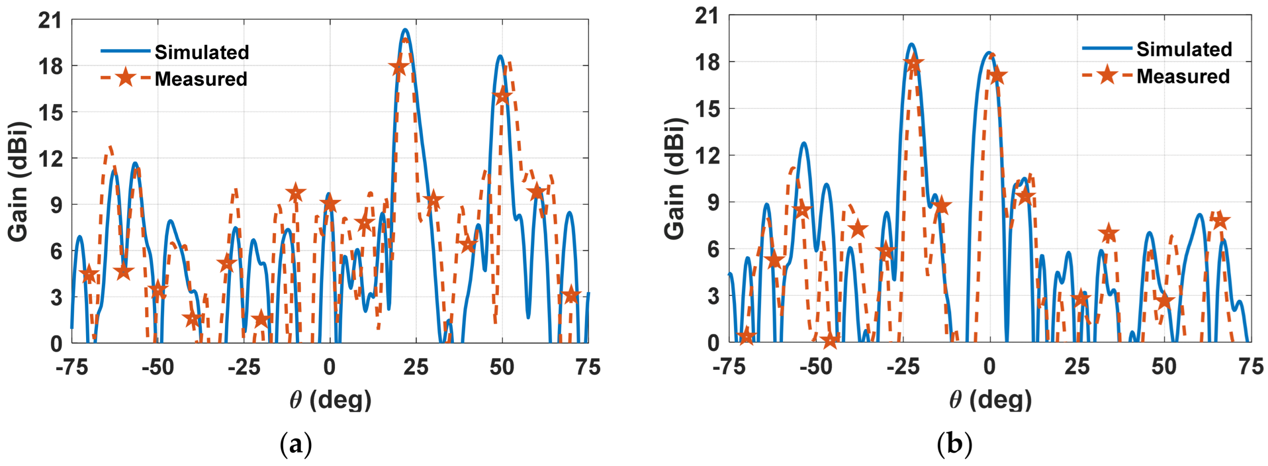
A Bambu Lab H2D printer with a nozzle of 0.4 mm has been used for prototyping. The two circular TAs, which are discretized into several square unit cells with a period of 4.29 mm, have a diameter of 128.6 mm and are spaced around 1 mm apart to avoid friction between the two dielectric TA panels. An open-ended waveguide (WR28) has been used as a feeder, spaced 64.3 mm from TA1 (i.e., F/D = 0.5). The radiative performance of the fabricated dual-beam mechanical scanning TA has been experimentally characterized using a vector network analyzer (Anritsu Shockline MS46524B) and another WR28 waveguide as a receiver. The comparison between the measured and simulated SMB antenna gain patterns as a function of the θ angle in a principal plane (ϕ = 0°) is reported in Figure 11. In the most extreme beam-pointing direction (Figure 11a), the measured radiation pattern exhibits peak gain values of 19.7 dBi and 18.4 dBi at steering angles θ = 21° and θ = 51°, respectively, with a PSLL = −7 dB. Upon rotating TA2 by 180°, both main lobes are shifted toward negative angles, providing measured gain values of 18 dBi and 18.5 dBi at θ = −22° and θ = 0°, respectively, while maintaining the PSLL close to −7 dB (Figure 11b). By comparing the radiative performance of a lossy mechanical scanning TA panel with that of an ideal lossless counterpart, a gain reduction of 0.4 dB was observed. This corresponds to a radiation efficiency of around 90%.
The measured and simulated radiation patterns are in satisfactory agreement, despite some discrepancies in the sidelobe regions and a slight misalignment of the main beam directions, probably due to fabrication tolerances and misalignments in measurements. This outcome assesses the validity of both the theoretical framework and the proposed synthesis methodology.
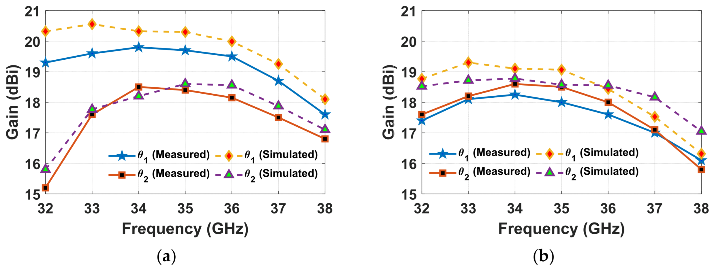
Finally, the frequency response of the fabricated dual-beam mechanically reconfigurable dielectric TA is reported in Figure 12 for two different TA panel rotations. The agreement between simulations and measurements is satisfactory. It is worth observing that in the case of ω1 = ω2 = 0° (Figure 12a) beam #2 (i.e., θ2) exhibits a lower gain than beam #1 (i.e., θ1), along with a narrower frequency response, since it is steered at the edge of the field of view.
It is worth noting that, although the 3D-printed mechanically steerable TA multi-beam prototype was experimentally characterized only for configurations in which the dual-beam radiation pattern lies in the principal planes, full-wave simulations reported in Figure 6 and Figure 7 demonstrate its 2D mechanical-steering SMB operation.
Table 1 summarizes the advantages of the proposed strategy for designing a mechanically reconfigurable TA that enables PtM communications through dual-beam radiation with 2D scanning capability, with respect to other TA designs.

5. Conclusions

A mechanically reconfigurable TA enabling PtM communications through SMB radiation is presented. The architecture employs two independently rotating planar dielectric TAs whose permittivity profiles are rigorously synthesized to convert the feeder spherical wavefront into multiple concurrent beams. The results highlight a 3 dB concurrent dual-beam gain bandwidth larger than 18% with a maximum scan angle of 55°.
For demonstration, a mechanical scanning fully dielectric TA prototype has been manufactured through 3D printing processes. The measured and simulation results are in good agreement, confirming the reliability of the described design process.
The proposed 2D mechanical-steering SMB scanning synthesis has been evaluated for two concurrent beams. Future improvements could be achieved by considering multi-beam radiation with more than two main peaks.

Author Contributions

Conceptualization, F.A.D. and S.G.; methodology, F.A.D. and S.G.; investigation, F.A.D. and S.G.; resources, S.G.; writing—original draft preparation, F.A.D.; supervision, S.G. All authors have read and agreed to the published version of the manuscript.

Funding

This work was partially supported by the Italian Ministry of Education and Research (MIUR) in the framework of the Crosslab and Forelab projects (Departments of Excellence). This work was partially supported by the project Silicon Micromachining for Multifunctional Terahertz Electromagnetic Surfaces sponsored by Consiglio Nazionale delle Ricerche (CNR) as part of “progetto di ricerca autofinanziato”, funding number (DIT.AD001.233).

Data Availability Statement

The original contributions presented in this study are included in the article. Further inquiries can be directed to the corresponding author.

Conflicts of Interest

The authors declare no conflicts of interest.

References

  1. Song, L.-Z.; Wen, Y.; Sauleau, R.; Qin, P.-Y.; Maci, S.; Guo, Y.J. Empowering Future 6G Wireless Networks with Transmitarray Antennas: A Review. IEEE Trans. Antennas Propag. 2025, 74, 125–140. [Google Scholar] [CrossRef] [Scilit]
  2. Ali, Q.; Shahzad, W.; Ahmad, I.; Safiq, S.; Bin, X.; Abbas, S.M.; Sun, H. Recent Developments and Challenges on Beam Steering Characteristics of Reconfigurable Transmitarray Antennas. Electronics 2022, 11, 587. [Google Scholar] [CrossRef] [Scilit]
  3. Cai, Y.; Matos, S.A.; Mei, P.; Felício, J.M.; Fernandes, C.A.; Costa, J.R.; Zhang, S. Design of Broadband Low-Profile Transmitarrays at Ka-Band With High-Permittivity 3-D-Printed Materials. IEEE Trans. Antennas Propag. 2025, 73, 8972–8980. [Google Scholar] [CrossRef] [Scilit]
  4. Dicandia, F.A.; Genovesi, S. Characteristic Modes Analysis for Circularly Polarized 1-Bit Dual-Layer Transmitarray Design. IEEE Open J. Antennas Propag. 2024, 5, 112–123. [Google Scholar] [CrossRef] [Scilit]
  5. Dicandia, F.A.; Genovesi, S. Analysis of Performance Enhancement of Clustered-Based Phased Arrays Employing Mixed Antenna Element Factor. IEEE Trans. Antennas Propag. 2024, 72, 1439–1448. [Google Scholar] [CrossRef] [Scilit]
  6. Chukhno, N.; Chukhno, O.; Pizzi, S.; Molinaro, A.; Iera, A.; Araniti, G. Approaching 6G Use Case Requirements with Multicasting. IEEE Commun. Mag. 2023, 61, 144–150. [Google Scholar] [CrossRef] [Scilit]
  7. Dicandia, F.A.; Genovesi, S. Simultaneous Multibeam Clustered Phased Arrays Analysis Using Mixed and Multiple Antenna Element Factors. Sensors 2024, 24, 7801. [Google Scholar] [CrossRef] [Scilit] [PubMed]
  8. Zaher, M.; Björnson, E.; Petrova, M. Cell-Free Beamforming Design for Physical Layer Multigroup Multicasting. IEEE Trans. Wirel. Commun. 2025, 25, 5262–5274. [Google Scholar] [CrossRef] [Scilit]
  9. Dicandia, F.A.; Fonseca, N.J.G.; Bacco, M.; Mugnaini, S.; Genovesi, S. Space-Air-Ground Integrated 6G Wireless Communication Networks: A Review of Antenna Technologies and Application Scenarios. Sensors 2022, 22, 3136. [Google Scholar] [CrossRef] [Scilit] [PubMed]
  10. Ma, Y.; Ma, R.; Lin, Z.; Miao, C.; Zhang, R.; Long, W.; Wu, W.; Wang, J. Distributed Split Single-Sideband Time-Modulated Arrays for Secure Communications. IEEE Internet Things J. 2026, 13, 23862–23875. [Google Scholar] [CrossRef] [Scilit]
  11. Zhi, L.; Hehao, N.; Yuanzhi, H.; Kang, A.; Xudong, Z.; Zheng, C.; Pei, X. Self-Powered Absorptive Reconfigurable Intelligent Surfaces for Securing Satellite-Terrestrial Integrated Networks. China Commun. 2024, 21, 276–291. [Google Scholar] [CrossRef] [Scilit]
  12. Dicandia, F.A.; Genovesi, S. Mechanically Steerable Simultaneous Multibeam Transmitarray Design by Analytical Multifocal Approach. IEEE Trans. Antennas Propag. 2024, 72, 9129–9142. [Google Scholar] [CrossRef] [Scilit]
  13. Jiang, Z.H.; Kang, L.; Yue, T.; Hong, W.; Werner, D.H. Wideband Transmit Arrays Based on Anisotropic Impedance Surfaces for Circularly Polarized Single-Feed Multibeam Generation in the Q-Band. IEEE Trans. Antennas Propag. 2020, 68, 217–229. [Google Scholar] [CrossRef] [Scilit]
  14. Xu, H.-X.; Cai, T.; Zhuang, Y.-Q.; Peng, Q.; Wang, G.-M.; Liang, J.-G. Dual-Mode Transmissive Metasurface and Its Applications in Multibeam Transmitarray. IEEE Trans. Antennas Propag. 2017, 65, 1797–1806. [Google Scholar] [CrossRef] [Scilit]
  15. Abdelrahman, A.H.; Nayeri, P.; Elsherbeni, A.Z.; Yang, F. Single-Feed Quad-Beam Transmitarray Antenna Design. IEEE Trans. Antennas Propag. 2016, 64, 953–959. [Google Scholar] [CrossRef] [Scilit]
  16. Guo, X.; Luo, Y.; Yan, N.; An, W.; Ma, K. Multibeam Transmit-Reflect-Array Antenna Using Alternating Transmission and Reflection Elements for Space–Air–Ground–Sea Integrated Network. IEEE Trans. Antennas Propag. 2023, 71, 8668–8676. [Google Scholar] [CrossRef] [Scilit]
  17. Liu, X.; Yan, Z.; Wang, E.; Zhao, X.; Zhang, T.; Fan, F. Multibeam Forming With Arbitrary Radiation Power Ratios Based on a Conformal Amplitude–Phase-Controlled Metasurface. IEEE Trans. Antennas Propag. 2023, 71, 3707–3712. [Google Scholar] [CrossRef] [Scilit]
  18. Song, L.-Z.; Wang, X.; Qin, P.-Y. Single-Feed Multibeam Conformal Transmitarrays With Phase and Amplitude Modulations. IEEE Antennas Wirel. Propag. Lett. 2022, 21, 1669–1673. [Google Scholar] [CrossRef] [Scilit]
  19. Piagge, A.D.; Dicandia, F.A.; Genovesi, S. Design of a Fully Dielectric Multibeam Transmitarray by Exploiting Amplitude and Phase Control. IEEE Trans. Antennas Propag. 2026. Early Access. [Google Scholar] [CrossRef] [Scilit]
  20. Zeng, Q.; Xue, Z.; Ren, W.; Li, W. Dual-Band Beam-Scanning Antenna Using Rotatable Planar Phase Gradient Transmitarrays. IEEE Trans. Antennas Propag. 2020, 68, 5021–5026. [Google Scholar] [CrossRef] [Scilit]
  21. Matos, S.A.; Fonseca, N.J.G.; Serra, J.C.; Felício, J.M.; Costa, J.R.; Fernandes, C.A. Generalized Risley Prism for Beam-Steering Transmit Arrays With Reduced Grating Lobes. IEEE Trans. Antennas Propag. 2023, 71, 8420–8428. [Google Scholar] [CrossRef] [Scilit]
  22. Bertrand, M.; Ruiz-García, J.; Allaeys, J.-F.; Ovejero, D.G.; Van Hoang, T.Q.; Loiseaux, B.; Sauleau, R.; Czarny, R.; Ettorre, M. Risley Scanner Using a Metasurface Source and a Single Deflector for SATCOM Applications. IEEE Trans. Antennas Propag. 2024, 72, 4839–4851. [Google Scholar] [CrossRef] [Scilit]
  23. Ahmed, F.; Afzal, M.U.; Hayat, T.; Esselle, K.P.; Thalakotuna, D.N. A Near-Field Meta-Steering Antenna System With Fully Metallic Metasurfaces. IEEE Trans. Antennas Propag. 2022, 70, 10062–10075. [Google Scholar] [CrossRef] [Scilit]
  24. Zhu, H.; Guo, L.; Ramer, R.; Kishk, A.A. Simultaneous Dual-Circularly Polarized 2-D Beam Scanning Low-Profile Folded Reflectarray. IEEE Trans. Antennas Propag. 2026, 74, 5396–5405. [Google Scholar] [CrossRef] [Scilit]
  25. CST Studio Suite. Available online: https://www.3ds.com/products/simulia/cst-studio-suite (accessed on 18 September 2025).
  26. Markel, V.A. Introduction to the Maxwell Garnett Approximation: Tutorial. J. Opt. Soc. Am. A 2016, 33, 1244–1256. [Google Scholar] [CrossRef] [Scilit] [PubMed]
  27. Tuloti, S.H.R.; Lamecki, A.; Mrozowski, M. An Optimized Ka-Band Low Profile Dual-Polarized Transmitarray Antenna With 2D Beam Switching. IEEE Access 2024, 12, 8924–8931. [Google Scholar] [CrossRef] [Scilit]
  28. Song, L.-Z.; Diao, Y.-Z.; Qin, P.-Y.; Ansari, M.; Von Loesecke, J.; Maci, S.; Guo, Y.J. A 3-D Printed Broadband Wide-Angle Multi-Beam Flat GRIN Lens Aided by Multifocal Ray-Path Analyses. IEEE Trans. Antennas Propag. 2024, 73, 22–32. [Google Scholar] [CrossRef] [Scilit]
  29. Vaquero, Á.F.; Teixeira, J.; Matos, S.A.; Arrebola, M.; Costa, J.R.; Felício, J.M.; Fernandes, C.A.; Fonseca, N.J.G. Design of Low-Profile Transmitarray Antennas With Wide Mechanical Beam Steering at Millimeter Waves. IEEE Trans. Antennas Propag. 2023, 71, 3713–3718. [Google Scholar] [CrossRef] [Scilit]
  30. Qu, Z.; Qu, S.-W.; Zhang, Z.; Yang, S.; Chan, C.H. Wide-Angle Scanning Lens Fed by Small-Scale Antenna Array for 5G in Millimeter-Wave Band. IEEE Trans. Antennas Propag. 2020, 68, 3635–3643. [Google Scholar] [CrossRef] [Scilit]
Figure 1. Sketch of the mechanically reconfigurable TA configuration comprising two rotatable circular apertures and a feeder.
Electronics 15 03144 g001
Figure 2. (a) Cascade of a dielectric TA unit cell, (b) equivalent TLM for the independent synthesis of the two permittivities (i.e., εri,1 and εri,2) and (c) the equivalent TLM for the analysis.
Electronics 15 03144 g002
Figure 3. Coverage regions of a dual-beam mechanical scanning TA in the case of (a) θ11 = 0°, θ12θ2 = 22.5°, (b) θ11 = 10°, θ12θ12 = 22.5°, (c) θ11 = 10°, θ12 = 35° and θ2 = 11° and (d) θ11 = 5°, θ12 = 35° and θ2 = 11°.
Electronics 15 03144 g003
Figure 4. Synthesized permittivity profile for a dual-beam radiation system operating at f = 35 GHz with D = 15 λ0, F/D = 0.5 and θ0_max = 50°; (a) TA1 and (b) TA2.
Electronics 15 03144 g004
Figure 5. Simulated dual-beam gain pattern for two rotation configurations at ϕ = 0°, f = 35 GHz and θ0_max = 50°.
Electronics 15 03144 g005
Figure 6. Simulated normalized RP of the proposed mechanical scanning TA for ω1 = 0°, ω2 = 90°, f = 35 GHz and θ0_max = 50°.
Electronics 15 03144 g006
Figure 7. Simulated dual-beam gain pattern as a function of u for v = v0 = 0.38 of the proposed mechanical scanning TA for ω1 = 0°, ω2 = 90°, f = 35 GHz and θ0_max = 50°.
Electronics 15 03144 g007
Figure 8. (a) Perforated dielectric unit cell and (b) the calculated effective permittivity at 35 GHz as a function of w.
Electronics 15 03144 g008
Figure 9. (a) Dual-beam gain and (b) the corresponding pointing directions (θ1 and θ2) as a function of the frequency of the proposed mechanical scanning TA for ω1 = ω2 = 0° and ω1 = 0°, ω2 = 180° with θ0_max = 50°.
Electronics 15 03144 g009
Figure 10. Manufactured mechanical scanning TA prototype; top view of (a) TA1, (b) TA2 and (c) perspective view of the whole mechanical scanning dielectric TA.
Electronics 15 03144 g010
Figure 11. Comparison between simulated and measured SMB gain as a function of θ of the proposed mechanical scanning TA at ϕ = 0° and f = 35 GHz; (a) ω1 = ω2 = 0° and (b) ω1 = 0°, ω2 = 180°.
Electronics 15 03144 g011
Figure 12. Comparison between simulated and measured SMB gain as a function of frequency of the proposed mechanical scanning TA; (a) ω1 = ω2 = 0° and (b) ω1 = 0°, ω2 = 180.
Electronics 15 03144 g012
Table 1. Comparison of the proposed mechanical scanning TA with respect to other design implementations.
Ref.RadiationFeederFixed/Scanning BeamF/DFabrication
[27]Single-beamMultiple sourcesBeam switching in fixed directions0.42PCB
[28]Single-beamMultiple sources located on a curved lineFixed beam0.753D printed
[29]Single-beamSingle sourceScanning beam in a plane (0–50°) with linear displacement0.343D printed
[30]Single-beamPhased arrayElectronic beam scanning in a plane ( ± 58°)N.A.3D printed
[21]Single-beamSingle source2D scanning beam up to 55° with rotatable platforms0.753D printed
[12]Dual-beamSingle sourceScanning beams in a plane (−25–50°) with linear displacement0.353D printed
[19]Dual-beamSingle sourceFixed0.753D printed
[17]Three-beamSingle sourceFixedN.A.PCB
[13]Quad-beamSingle sourceFixed0.8PCB
This workDual-beamSingle source2D scanning beams up to 55° with rotatable platforms0.53D printed
Disclaimer/Publisher’s Note: The statements, opinions and data contained in all publications are solely those of the individual author(s) and contributor(s) and not of MDPI and/or the editor(s). MDPI and/or the editor(s) disclaim responsibility for any injury to people or property resulting from any ideas, methods, instructions or products referred to in the content.