


Abstract
This paper investigates a near-field millimeter-wave (mmWave) integrated sensing and communication (ISAC) system under unknown interference. A base station equipped with a partially connected dynamic subarray hybrid architecture serves a legitimate user while performing target-oriented transmit beampattern shaping. Unlike existing works that assume perfect interference knowledge, we characterize the unknown interference channels via a robust spatial covariance uncertainty model. To exploit spatial degrees of freedom for interference suppression, the user employs a fully connected hybrid receiver. We formulate a robust transmit power minimization problem subject to worst-case communication signal-to-interference-plus-noise ratio (SINR) and sensing beampattern constraints, alongside constant-modulus and dynamic subarray hardware constraints. To solve this highly non-convex mixed discrete–continuous problem, we propose a two-layer alternating optimization framework. The inner layer optimizes the continuous and phase-quantized beamformers using successive convex approximation, while the outer layer refines the binary subarray connections via a penalty-augmented local discrete search. Extensive simulations demonstrate that explicitly modeling worst-case uncertainties ensures reliable ISAC performance in adversarial environments, and the dynamic subarray architecture systematically outperforms conventional fixed topologies in power efficiency. Additional robustness and sensitivity analyses show that these gains are most pronounced when sufficient spatial degrees of freedom remain, whereas excessive antenna failures, unmodeled strong multipath, or covariance drift outside the uncertainty envelope can erode the communication and sensing margins.
1. Introduction
In recent years, millimeter-wave (mmWave) communication equipped with massive multiple-input–multiple-output (MIMO) antenna arrays has emerged as a key enabling technology for high-rate wireless systems [1,2]. Since fully digital beamforming requires a dedicated radio frequency (RF) chain for each antenna element, its hardware cost and power consumption become prohibitive for large-scale mmWave arrays. Hybrid analog–digital beamforming therefore provides a practical architecture that balances implementation complexity and array gain: energy-efficient and low-resolution transceiver designs establish the hardware-motivated baseline [3,4], wideband and multi-user optimization methods address algorithmic scalability [5,6], and learning-aided or regularized hybrid designs further broaden the design toolbox [7,8]. Recent generative-model-based hybrid beamforming also illustrates the continuing development of data-driven large-array design [9]. Furthermore, as the number of antennas increases to extremely large scales to compensate for severe path loss, the Rayleigh distance expands significantly. This paradigm shift transitions the operating environment from the conventional far-field planar-wave model to the near-field spherical-wave model (i.e., the Fresnel region), fundamentally altering the spatial channel characteristics [10,11]; it also introduces spatial wideband and CSI-transfer issues that require dedicated near-field treatment [12].
Concurrently, integrated sensing and communication (ISAC) has garnered significant attention, as it leverages shared hardware platforms and spectral resources to simultaneously support communication and sensing functionalities. General joint radar–communication studies summarize the broader ISAC design space [13], while mmWave beamformer optimization and short-packet Pareto design show how sensing–communication tradeoffs appear in high-frequency arrays [14,15]. This dual-functional paradigm renders the beamforming design fundamentally multi-objective, necessitating a delicate balance between communication quality-of-service (QoS) and sensing accuracy. Recently, hybrid beamforming has been extensively investigated in ISAC systems to achieve this tradeoff cost-effectively. Narrowband and compressed-sampling mmWave ISAC formulations motivate hybrid transceiver design for shared sensing and communication [16,17], whereas wideband extensions address frequency-selective hybrid ISAC operation [18]. These developments enable capabilities such as multi-static cooperative localization and target tracking [19,20]. In parallel with beamforming-oriented ISAC studies, waveform and sequence design has also become an important layer of the ISAC literature. For example, the recently proposed DRIP family develops versatile space-time discrete-time sequences for ISAC signaling [21]. These works are complementary to the present study: sequence-level designs improve the temporal and spectral structure of shared signals, whereas our focus is the spatial hybrid-beamforming and subarray-reconfiguration layer for near-field robust power minimization.
Despite these advances, deploying ISAC systems in hostile electromagnetic environments introduces exceedingly challenging security and robustness issues. The broadcast nature of wireless signals makes ISAC systems vulnerable to malicious eavesdropping and intentional interference [22,23]. Recent communication-oriented studies have addressed anti-jamming or anti-interference hybrid beamforming for mmWave massive MIMO [24,25], secrecy-oriented hybrid beamforming for satellite-terrestrial and extended-reality links [26,27], and secure or adaptive hybrid precoding under signal-domain or platform-perturbation impairments [28,29]. Robust covariance-matrix reconstruction is also relevant to interference-statistics estimation in adaptive beamforming [30]. However, these studies predominantly focus on communication-only systems, secure links without explicit sensing constraints, or statistical interference processing without dynamic ISAC subarray design. In practical adversarial scenarios, however, the exact channel state information (CSI) of interferers is typically inaccessible, and the legitimate channels are subject to estimation errors. Furthermore, the sensing signals themselves can be exploited to generate artificial noise (AN) to counter eavesdroppers or suppress interference. Secure ISAC and covert mmWave hybrid MIMO designs directly motivate this use of auxiliary or sensing-related emissions [22,31], while high-frequency physical-layer security studies further show the value of spatial signal shaping against unauthorized reception [32]. However, such protection requires sophisticated beamforming designs that are robust against CSI uncertainties.
To further enhance the spatial degrees of freedom (DoFs) under limited RF chains, partially connected structures have been extensively studied as an even more cost-effective alternative to fully connected hybrid beamforming. Sub-connected relay and multi-user partially connected designs demonstrate the architectural feasibility of this approach [33,34], while energy-efficiency studies with low-resolution converters quantify its hardware-efficiency advantage [35]. Building upon this, dynamic subarray architectures have been proposed, which adaptively optimize the antenna-to-RF-chain connections. Hybridly connected and reconfigurable subarray structures provide the main architectural basis for such topology adaptation [36,37], and joint precoding in sub-connected systems further supports the need to co-design the connection topology with the digital/analog beamformers [38]. By dynamically reconfiguring the subarray topology, these architectures can significantly improve spectral efficiency and interference suppression capabilities [22]. However, existing studies typically focus on isolated aspects such as spectral-efficiency maximization, interference robustness [24], sensing beampattern shaping, or subarray architecture optimization [37,38]. There remains a distinct lack of a unified framework for near-field mmWave massive hybrid array systems that jointly accounts for ISAC, unknown adversarial interferers, imperfect CSI, and dynamic subarray design.
In this paper, motivated by this gap, we investigate a near-field partially connected massive hybrid array system serving a legitimate user and a sensing target in the presence of multiple unknown interferers. To effectively suppress unknown interference signals, the legitimate user is equipped with a multi-antenna fully connected hybrid receiver, which provides the necessary spatial DoFs for interference mitigation. Meanwhile, the sensing functionality is represented through transmit-side near-field beampattern shaping. The main contributions of this paper are summarized as follows:
- (1)
- We establish a comprehensive near-field ISAC system model with a dynamic subarray hybrid beamforming architecture at the base station (BS) and a fully connected hybrid receiver at the user. We formulate a narrowband robust transmit power minimization problem subject to a communication signal-to-interference-plus-noise ratio (SINR) requirement and transmit-side sensing beampattern constraints.
- (2)
- To address the unknown interference channels and imperfect CSI, we characterize the interferers via a robust spatial covariance uncertainty model and the legitimate channel via a bounded error model. The semi-infinite robust constraints are then rigorously transformed into deterministic, mathematically tractable surrogates.
- (3)
- We develop a two-layer alternating optimization (AO) framework to solve the highly non-convex mixed discrete–continuous design problem. The inner layer optimizes the continuous and phase-quantized beamforming variables using successive convex approximation (SCA), while the outer layer refines the binary dynamic subarray connections via a penalty-augmented local discrete search.
- (4)
- Extensive simulations validate the superiority and limitations of the proposed framework. The simulation study also evaluates initialization sensitivity, partial antenna failures, strong near-field specular reflections, sensing-gain fluctuation, covariance drift, and a small-scale exhaustive topology benchmark. The results demonstrate that explicitly modeling worst-case uncertainties saves significant transmit power in adversarial environments, and the dynamic subarray architecture systematically outperforms conventional fixed topologies across various hardware configurations and system requirements.
The remainder of this paper is organized as follows. Section 2 presents the near-field ISAC system model, including the hybrid transceiver architecture, the ISAC signal model and performance metrics, and the CSI and interference uncertainty models. Section 3 formulates the robust transmit power minimization problem and derives deterministic tractable reformulations. Section 4 develops the two-layer alternating-optimization framework, combining inner-layer successive convex approximation for continuous and quantized beamforming variables with outer-layer local search over the dynamic subarray connections. Section 5 reports numerical simulations and discusses beamforming behavior, robustness, and comparisons with baselines. Section 6 concludes the paper.
Unless stated otherwise, scalars are denoted by italic letters, vectors by bold lower-case letters, and matrices by bold upper-case letters. The superscripts and denote transpose and conjugate transpose (Hermitian), respectively. and denote the Euclidean norm of a vector and the Frobenius norm of a matrix, respectively; is the trace. and denote the real part and the phase of a complex scalar, respectively. ⊙ denotes the Hadamard (element-wise) product. For Hermitian matrices, means that is positive semidefinite (PSD). denotes statistical expectation; denotes the circularly symmetric complex Gaussian distribution. is the identity matrix, and denotes the minimum eigenvalue of a Hermitian matrix.
2. System Model
2.1. Near-Field Channel and Hybrid Transceiver Architecture
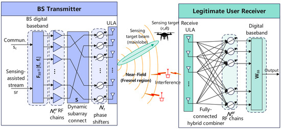
Consider a narrowband near-field mmWave ISAC system comprising a base station (BS), a legitimate user, a sensing target, and J unknown interferers. As shown in Figure 1, the BS is equipped with an -element uniform linear array (ULA) driven by RF chains, where . A partially connected hybrid transmit architecture is employed at the BS [36], where each antenna is connected to exactly one RF chain. Similarly, the legitimate user is equipped with an -antenna ULA and RF chains (), employing a fully connected hybrid receive combiner. The sensing target and the legitimate user are assumed to be located in the Fresnel (near-field) region of the BS transmit array [10]. The interferers may occupy arbitrary spatial locations relative to the BS and the user array; however, their exact CSI is inaccessible at the BS. Consequently, their aggregate effect is absorbed into a covariance-based robust interference model. Without loss of generality, the center of the BS array is chosen as the origin of the coordinate system. The coordinate of the n-th BS antenna element is given by for , and the coordinate of the m-th receive antenna at the legitimate user is for , where is the inter-element spacing and is the carrier wavelength.
Figure 1.
The near-field ISAC system model.
For a generic point located at a distance r and angle relative to the array center, the distance between the point and the n-th BS transmit antenna is . The corresponding near-field transmit steering vector, which captures the spherical wavefront [10], is defined as
Similarly, the distance between the generic point and the m-th receive antenna at the user is . The corresponding near-field receive steering vector is given by
Note that when the propagation distance r is sufficiently large (i.e., exceeding the Rayleigh distance), the near-field steering vectors naturally degenerate to the standard far-field planar-wave steering vectors.
The legitimate user is located at , and, under the standard separable spherical-wave channel approximation, the BS-to-user channel is modeled by a near-field geometric channel [1,10] with effective paths
where is the complex gain of the ℓ-th path, and are the effective transmit and receive angles, and and are the effective near-field distances seen from the transmit and receive arrays, respectively. To facilitate tractable analysis while capturing the fundamental near-field propagation characteristics, we postulate a line-of-sight (LoS) dominant link, under which the channel is well-approximated by
where is the complex gain of the LoS path, and are the effective transmit and receive angles, and denotes the center-to-center BS–user distance. This LoS-dominant model is adopted as the baseline channel used for tractable derivation and numerical comparison, but the proposed robust formulation is not restricted to a single physical path. If strong near-field specular reflections are resolvable or estimable, they can be included in the nominal multi-path channel through the summation model above. If they are not explicitly modeled, their aggregate effect is treated as part of the residual CSI mismatch and is protected only when the induced perturbation remains within the adopted radius . Rapidly appearing strong reflections outside this envelope therefore constitute an out-of-set mismatch and are not covered by the formal worst-case guarantee.
The sensing target is located at and is represented by the near-field target steering vector . To enhance the spatial degrees of freedom (DoFs) of the partially connected architecture, we introduce a dynamic subarray mechanism at the BS. This mechanism is motivated by hybridly connected and reconfigurable subarray architectures [36,37], while the need to jointly optimize sub-connected precoding variables is supported by recent joint-precoding studies [38]. Let denote the dynamic subarray connection matrix, where its elements are defined as
The partially connected structure requires that each transmit antenna is connected to exactly one RF chain, i.e., for all . To avoid empty RF branches, we further impose that each RF chain serves at least one antenna, i.e., for all . The BS analog precoder is then defined as , where is the complex phase matrix. For each active connection where , the constant-modulus constraint is given by , where . Assuming finite-resolution phase shifters, the phase of the active elements must belong to a discrete set , where B is the number of quantization bits for the phase shifters. For notational simplicity, the same B-bit quantization set is adopted at the receiver.
At the legitimate user, a fully connected hybrid receive combiner is employed to suppress the unknown interference. Given the massive number of antennas at the BS (), a fully connected architecture would incur prohibitive power consumption from phase shifters; hence, the dynamic partially connected structure is adopted. Conversely, the user is equipped with fewer antennas but faces severe unknown interference, necessitating a fully connected architecture to maximize spatial degrees of freedom (DoFs) for precise interference nulling. This design choice explicitly avoids the need for an antenna activation matrix (i.e., no matrix is required at the user side). Let the user-side analog combiner be and the digital combiner be . The overall receive combiner is . The analog combiner is subject to constant-modulus constraints for all its entries, i.e., for all . The receive-side phase shifters are also quantized according to the same codebook .
2.2. ISAC Signal Model and Performance Metrics
To support ISAC, the BS transmits a dual-functional waveform composed of a communication stream and a sensing-assisted stream [14,22]. The transmitted signal vector is , where are the digital beamformers for communication and sensing, respectively. The data streams are assumed to be independent and normalized such that and . For compactness, the transmit signal can be equivalently expressed as , where and . The transmit covariance matrix is given by
and the total transmit power is .
At the legitimate user, the received signal is corrupted by noise and the aggregate interference signal , where is the channel from interferer j to the user and is the zero-mean interference signal emitted by interferer j [24]. The pre-combining receive vector is , where is the additive white Gaussian noise (AWGN). After applying the hybrid receive combiner , the scalar output is . Since the sensing-assisted stream does not carry desired communication information, it acts as self-induced interference. The post-combining communication SINR is defined as
where is the spatial covariance matrix of the aggregate interference, which can capture both independent and mutually correlated interferer emissions.
In this paper, the sensing functionality is evaluated via a transmit-side beampattern proxy [15]. Specifically, we adopt the transmit illumination gain as the primary sensing design metric, thereby circumventing the need to explicitly model echo reception, clutter dynamics, and downstream detection/estimation processing. The transmit gain at an arbitrary near-field point is defined by
At the target location , the desired sensing gain is
Let denote a prescribed non-target angle-range region, excluding a guard region around the sensing target, over which sidelobe suppression is required.
2.3. CSI and Interference Uncertainty Models
In practical adversarial scenarios, the exact CSI of the legitimate user, the precise location of the sensing target, and the channels of the interferers are typically subject to estimation errors or are completely unavailable. We model the estimated legitimate MIMO channel as , where is the estimated channel and is the bounded CSI error satisfying . Here, is the nominal near-field CSI dictated by the LoS-dominant model in Section 2.1. The spherical-wave geometry is therefore retained in the nominal channel response; the Frobenius-norm uncertainty is not intended to replace this geometry. Instead, is used as an engineering robustness envelope for the residual error after range, angle, synchronization, array-calibration, and model-mismatch effects have been absorbed into the estimated channel. A physically meaningful radius can be selected as an outer bound on the channel perturbations induced by the expected range-angle error region,
where denotes the admissible physical localization-error set, and and summarize residual calibration and model errors. This construction is conservative: it encloses the structured near-field manifold inside a tractable matrix-norm ball. The benefit is that the resulting robust SINR bound remains solvable within the mixed discrete–continuous hybrid-beamforming problem, whereas directly optimizing over range-angle perturbation manifolds would lead to highly non-convex semi-infinite constraints. If the actual physical mismatch exceeds the adopted radius, the formal worst-case guarantee should no longer be interpreted as strict.
The target location is subject to estimation errors bounded by maximum uncertainty radii and for range and angle, respectively. However, due to the severe spatial wideband effect and rapid phase variations in the near field, directly mapping physical location errors to the steering vector via Taylor expansion is mathematically invalid for practical error bounds. Instead, we construct a tractable ellipsoidal uncertainty set directly on the steering vector manifold:
where is the nominal steering vector, is the normalized perturbation vector, and is a shape matrix designed to bound the worst-case phase variations within the physical error region. This ellipsoidal envelope provides a mathematically rigorous and tractable surrogate for near-field robustness.
Consequently, the target steering vector is uncertain, i.e., . Since the interferers are uncooperative, their exact CSI is unobtainable at the BS [24]. Therefore, we model the aggregate interference through a robust spatial covariance uncertainty set , where is a sample covariance matrix, or equivalently its PSD-projected estimate, and is the uncertainty radius. In practice, can be obtained from interference-dominant snapshots collected during guard/silent resources, sensing listen-only intervals, or data-aided residual observation after subtracting the reconstructed desired communication and sensing components. Given L snapshots , a typical implementation forms
where denotes projection onto the positive-semidefinite cone and is the calibrated noise-floor estimate. In dynamic environments, this covariance may be refreshed using a sliding window or an exponential update . The radius should cover finite-sample covariance error, residual desired-signal subtraction error, and temporal drift over the update interval; for instance, it can be chosen from validation residuals or as a high-percentile bound on . The robust guarantee applies when the true covariance remains inside ; if the interference statistics drift outside this set, the design must update either , , or both.
3. Problem Formulation and Deterministic Reformulation
3.1. Original Robust Power-Minimization Problem
The design variables are the dynamic subarray matrix , the transmit phase matrix , the communication and sensing digital beamformers and , the user analog combiner , and the user digital combiner . With and , the robust transmit power minimization problem is formulated as
In problem , the objective function and the constraints possess the following physical interpretations:
- (13a) is the objective function, which aims to minimize the total transmit power at the base station, represented by .
- (13b) ensures that the worst-case post-combining communication SINR meets the minimum requirement , guaranteeing reliable communication for the legitimate user despite bounded CSI errors and unknown interference covariance .
- (13c) guarantees that the worst-case transmit illumination gain toward the sensing target exceeds the threshold , ensuring robust sensing performance under target location uncertainties .
- (13d) enforces a spatial sidelobe suppression bound over the predefined non-target region , which mitigates sensing interference to other directions and reduces the risk of being intercepted by interferers.
- (13e) defines the partially connected hybrid precoding structure via , combining the binary connection matrix and the phase shift matrix .
- (13f)–(13h) specify the dynamic subarray topology. Specifically, (13f) ensures each transmit antenna is connected to exactly one RF chain; (13g) prevents empty RF chains by ensuring each chain serves at least one antenna; and (13h) restricts the connection indicators to binary values.
- (13i) and (13j) represent the constant-modulus hardware constraints of the phase shifters. For the transmitter (13i), the power is normalized by the dynamically assigned subarray size ; for the fully connected receiver (13j), it is normalized by the total number of receive antennas .
- (13k) and (13l) impose the finite-resolution (quantized) phase constraints on the active transmit and receive phase shifters, restricting their phases to the B-bit codebook .
Problem is highly non-trivial to solve directly due to the semi-infinite robust constraints, the binary subarray variables, the constant-modulus and quantized phase constraints, and the strong coupling among the transmit and receive beamforming variables.
3.2. Deterministic Tractable Reformulation of Robust Constraints
To derive a tractable design formulation, we proceed to recast the semi-infinite constraints in into deterministic robust counterparts or locally accurate surrogates. Regarding the user-channel uncertainty, the ensuing communication-side reformulation should be interpreted as providing worst-case protection around the nominal near-field channel, bounded by the adopted unstructured CSI envelope.
First, for any fixed receive combiner , the worst-case interference covariance admits a closed-form characterization.
Lemma 1.
For any given , the worst-case aggregate interference power over the uncertainty set satisfies
Proof.
By writing and using the Frobenius Cauchy–Schwarz inequality, we obtain
Because and , we obtain the upper bound
If , the claim is immediate. Otherwise, equality is attained by choosing
which belongs to because , , and . Therefore, the stated maximum is achieved. □
Accordingly, define the effective worst-case interference-plus-noise covariance . Next, introduce an auxiliary scalar to upper bound the post-combining interference-plus-noise term. Because the desired-signal term and the self-interference term depend on the same CSI error matrix , the following split is adopted as a conservative sufficient condition for the robust SINR constraint
By the Frobenius Cauchy–Schwarz inequality, for any ,
Therefore, the above sufficient condition can be tractably enforced through the following deterministic second-order-cone type constraints:
It is worth noting that these inequalities constitute sufficient, albeit generally not necessary, conditions for the original robust SINR constraint. The inherent conservatism originates from two primary sources: first, the identical CSI perturbation is decoupled across the desired-signal and self-interference terms via the auxiliary variable ; second, each constituent term is subsequently upper-bounded using norm inequalities. Consequently, this approximation may conservatively overestimate the transmit power required to guarantee robustness. While tighter bounds (e.g., via the S-procedure or Nemirovski Lemma) exist for quadratic forms, applying them to the fractional SINR term coupled with mixed-integer variables (dynamic subarrays) and quantized phases would render the subproblems computationally prohibitive. The adopted decoupling strategy strikes a necessary balance, providing a strictly tractable lower bound for the highly non-convex mixed-discrete optimization.
For the sensing constraint, we adopt the ellipsoidal steering vector uncertainty model from Section 2.3, where with . To construct the shape matrix , we utilize the spatial gradients:
where and . The scaling factors and are chosen to empirically cover the target region. While this gradient-based shape matrix acts as a local surrogate, enforcing robustness over the entire ellipsoid provides a significantly wider protection margin than a nominal design.
The corresponding robust transmit-side illumination constraint is thus written as
For the above locally linearized semi-infinite constraint, a convenient sufficient LMI condition is that there exists a slack variable such that
This LMI should therefore be interpreted as a robust target-illumination guarantee for the adopted local beampattern proxy, rather than as a guarantee for a complete sensing receiver or detector.
Finally, the continuous sidelobe region is numerically represented by a dense design grid , and the continuous sidelobe requirement is approximated by the finite set of inequalities for . The approximation quality improves as the grid is refined; no exact between-grid guarantee is claimed in the present formulation.
3.3. Tractable Approximate Design Problem
Combining the above deterministic reformulations yields the following tractable approximate design problem used below:
Problem affords a much cleaner robust interpretation than : constraints (26b) and (26c) jointly establish a conservative sufficient guarantee for the worst-case communication SINR, constraint (26d) enforces robust target illumination bounded by the adopted local near-field linearization model, and constraint (26e) imposes stringent sidelobe control over a dense spatial grid. Consequently, serves as a mathematically tractable surrogate of rather than a strictly equivalent reformulation. Nevertheless, remains non-convex due to the coupled hybrid beamforming variables, the discrete phase constraints (26l) and (26m), and the binary dynamic subarray matrix (26i).
4. Alternating-Optimization Algorithm
4.1. Algorithmic Principle
Despite the deterministic reformulations, Problem remains challenging due to three primary factors: (1) the transmit and receive beamformers remain strongly coupled; (2) even under the adopted local near-field linearization, the target-gain constraint is non-convex with respect to the beamforming variables, necessitating iterative convexification; and (3) the phase-quantized analog beamformers and the binary subarray matrix yield a highly non-convex mixed discrete–continuous design space. To circumvent these intractable issues, we develop a two-layer alternating optimization (AO) framework:
- (1)
- An inner-layer hybrid beamforming update for fixed subarray assignment ;
- (2)
- An outer-layer dynamic subarray refinement based on local discrete search.
For the discrete updates, it is convenient to introduce a penalty-augmented merit function that measures both transmit power and current constraint violations. Define
and the scalar violation functions
With , the merit function is chosen as
where are penalty parameters. When all constraints are satisfied, reduces to the transmit power objective. This merit function is used to guide the discrete updates of , , and . Note that although the minimum eigenvalue function is non-differentiable when multiple minimum eigenvalues exist, it is only evaluated as a scalar merit metric during the backtracking line search and discrete coordinate descent, thus avoiding any requirement for its gradient.
4.2. Inner-Layer AO for Fixed Subarray
For a fixed dynamic subarray matrix , the corresponding active set is determined, and only the continuous or phase-quantized beamforming variables need to be updated. The inner-layer AO contains four steps.
- (1)
- Digital receive combiner update.
Let and , and define the interference-plus-noise covariance at the user as . For a fixed analog combiner , the digital combiner is updated by maximizing the following receive-SINR surrogate generalized Rayleigh quotient
When is nonsingular, the exact maximizer is given, up to a nonzero scaling factor, by
In scenarios where the effective interference covariance becomes singular or numerically ill-conditioned, we resort to a Tikhonov-regularized update direction to ensure numerical stability
where is a small predetermined regularization parameter. In the implementation, it is selected as a numerical eigenvalue floor rather than as a new physical design variable. Specifically, we use
with a small floor and . This trace-normalized choice scales the diagonal loading with the average effective interference-plus-noise power while preventing numerical singularity when the covariance rank is reduced by analog combining. In the simulations, is used, and the same value is adopted whenever the trace-normalized term is smaller. The regularization only stabilizes the surrogate receive-combiner direction; accepted updates are still subject to the penalty-merit decrease test. Let denote the normalized version of either the exact maximizer or the regularized direction above. To ensure monotonic decrease of the penalty merit function, the accepted update is taken as
where is chosen by backtracking so that does not increase; in implementation, the search starts from and repeatedly shrinks it as with a fixed until the first acceptable step is found. If no positive step size yields a decrease, we set and keep the current iterate. This receive-digital update is surrogate-based rather than the exact -block optimizer of ; its role is to provide a low-cost nominal-SINR trial direction that is retained only when the full penalty merit function decreases.
- (2)
- Analog receive combiner update.
With fixed, the analog combiner is updated by discrete coordinate descent over the quantized codebook. For each entry , the feasible set is . Keeping all other entries unchanged, the new value of is chosen as . All entries are cyclically updated until the decrease in becomes smaller than a prescribed threshold. This update is monotonic because each coordinate is optimized over a finite set while the other coordinates are fixed.
- (3)
- Digital transmit beamformer update.
For fixed , the digital block is optimized by an inner successive convex approximation (SCA). Define
for . At the q-th SCA step, let , , and be the current digital iterate, with , where is a small predetermined numerical safeguard. Since the global phase of does not affect either the objective or the quadratic power terms, we use the phase-aligned lower bound
If , we simply set , since any phase choice yields the same real-part lower bound at that degenerate point.
In addition, because is concave, its first-order Taylor expansion at gives a global upper bound . To obtain an explicit affine surrogate for the target-LMI terms, define for each
Then, can be rewritten as
Using the PSD identity , we obtain the Loewner lower bound
Accordingly, the explicit affine surrogate is defined as
which satisfies for all .
Using these relations, the digital variables are updated by solving the following convex surrogate problem at the q-th iteration, where , and are auxiliary variables introduced to reformulate the non-convex terms into convex constraints:
Problem is convex and can be efficiently solved by standard interior-point solvers. Note that the convex quadratic constraint (43f) can be equivalently recast as a standard second-order cone (SOC) constraint , which facilitates efficient implementation in such solvers.
Before the first SCA solve (), an initial digital point must be specified. In practice, and can be obtained by projecting the estimated user and target steering vectors, respectively, onto the current RF-precoder subspace, while is initialized no smaller than . If this initialization renders the first convex surrogate infeasible, we solve a one-time slack-augmented feasibility-restoration problem at the current linearization point to obtain a workable starting point. Introduce nonnegative slacks , and , together with positive weights , and solve
Problem is convex. In practice, it is used only when the first surrogate subproblem is infeasible; its solution is then taken as the reset current iterate before re-solving . A numerically large optimal aggregate slack indicates that the initialization is too aggressive for the adopted requirements or uncertainty radii.
Let denote the solution of the current convex surrogate . The accepted update is obtained through damping, for , with the same rule applied to and , where is selected so that is non-increasing. As in the receive-digital step, the line search starts from and shrinks geometrically by the same factor until the first merit-decreasing step is found. If no positive step size yields a merit decrease, we set and retain the current digital iterate. The SCA loop is repeated until both the relative decrease in the convex surrogate objective and the relative decrease in become negligible.
- (4)
- Quantized analog transmit phase update.
For fixed , the analog transmit phase matrix is refined by discrete coordinate descent. For each active entry satisfying , the feasible set is . Keeping all remaining entries fixed, the update is . The entries are successively visited over all active antenna–chain pairs until the decrease in becomes sufficiently small. Since each coordinate is optimized over a finite codebook, the merit function is monotonically non-increasing during this step.
4.3. Outer-Layer Dynamic Subarray Update
After the inner-layer beamformer update converges for the current , the dynamic subarray is refined by one-antenna local search. Specifically, for each antenna n, let denote its currently assigned RF chain. For every candidate chain , construct a tentative reassignment matrix satisfying and while keeping all other rows unchanged. Candidates that violate the non-empty-subarray condition are discarded. The unchanged assignment is also retained as a feasible baseline candidate. For each feasible tentative reassignment, the variables are temporarily kept at their latest inner-layer values, and
- (1)
- The new subarray sizes are computed;
- (2)
- The magnitudes of the active entries of are renormalized according to the updated ;
- (3)
- One fast transmit-phase refinement sweep is carried out using the rule in Step 4 above, yielding an associated refined phase matrix denoted by ;
- (4)
- The corresponding merit value is evaluated.
The reassignment for antenna n is chosen as
where denotes the set of feasible destination chains for antenna n other than the current one, and by convention, denotes the unchanged current assignment. Once is selected, both the accepted subarray row and the corresponding refined transmit phase matrix are updated according to . After all antennas are visited once, the resulting matrix is denoted by . The outer-layer search terminates when one complete sweep over all antennas yields no further decrease in . While this greedy one-antenna search is heuristic and may converge to a local optimum, it avoids the prohibitive complexity of exhaustive search. Because the search is local in the discrete topology space, its final solution can depend on the initial subarray partition. We therefore use deterministic balanced contiguous or interleaved partitions as reproducible warm starts, and for deployment scenarios where initialization sensitivity is critical, a low-cost multi-start variant can run the same local search from several random feasible partitions and retain the lowest-merit solution. The initialization dependence is quantified in Section 5.6. In practice, alternating this search with the continuous beamformer updates provides substantial performance gains over fixed topologies.
4.4. Complete AO Procedure
The overall procedure of the proposed AO algorithm is summarized below. Let , , , , , , , , and denote the prescribed algorithmic parameters.
- (1)
- Initialize a feasible subarray matrix , for example, by balanced contiguous or round-robin partition.
- (2)
- Initialize using phase matching toward the estimated user direction, and initialize using phase matching toward the dominant receive steering vector.
- (3)
- Construct an initial digital point , for example, by projecting the estimated user and target steering vectors onto the column space of . Initialize as any positive scalar satisfying , and set an initial nonnegative . These quantities define the first SCA iterate, i.e., , for , together with and . If is infeasible, solve the slack-augmented restoration problem once and use its solution to reset the initial digital iterate before entering the standard SCA loop.
- (4)
- For outer iteration , execute the following substeps:
- (5)
- With fixed, run the inner-layer AO cycle until the relative decrease in becomes smaller than a prescribed threshold : update and , solve the SCA-based digital subproblem to update , and then update over the active transmit phases.
- (6)
- Evaluate the current merit value after the inner-layer convergence for the current .
- (7)
- Update the dynamic subarray matrix by one-antenna local search, simultaneously carrying forward the refined transmit phase matrix associated with each accepted reassignment, and obtain .
- (8)
- If the maximum constraint violation is below a prescribed tolerance and the relative reduction in is smaller than , terminate; otherwise, continue.
- (9)
- If the maximum constraint violation remains above the tolerance and its decrease over the latest outer sweeps is smaller than a prescribed threshold , increase the penalty parameters according to for with and repeat.
The final output is the tuple .
4.5. Algorithmic Interpretation and Descent Discussion
The proposed AO procedure is best interpreted as a pragmatic descent framework tailored for the penalized approximate problem associated with , rather than an exact block-coordinate solver for itself.
- (1)
- The digital receive combiner step optimizes a nominal generalized Rayleigh-quotient surrogate and then uses the merit-decrease test to accept or reject the resulting trial direction; when the nominal interference matrix is ill-conditioned, a small Tikhonov regularization is used to maintain numerical stability rather than claiming exact generalized-Rayleigh optimality in the singular case.
- (2)
- The digital transmit block is handled by SCA on the conservative approximate model, where the communication-related non-convex terms are locally convexified and the target-LMI-related rank-one PSD terms are replaced by explicit affine Loewner lower bounds.
- (3)
- The analog transmit and receive phase matrices are updated by exact per-coordinate minimization over their finite quantized codebooks.
- (4)
- The dynamic subarray matrix is updated by feasible local search directly driven by the penalty-augmented objective, and each accepted reassignment carries along its associated refined transmit phase matrix so that the actual iterate is consistent with the evaluated merit value.
Proposition 1
(fixed-penalty descent). Consider one phase of the proposed AO algorithm in which the penalty weights and the uncertainty radii are fixed. Suppose that each continuous trial point is accepted only if it does not increase , and each analog-phase or subarray candidate is selected from its finite feasible set by explicit merit comparison. Then the generated penalized merit sequence is monotonically non-increasing and converges in objective value because .
The proof follows directly from the update construction. The digital receive combiner uses a regularized generalized-Rayleigh direction followed by a backtracking merit test; the SCA-based digital transmit update is damped and accepted only when the current merit does not increase; the finite-resolution analog phase update performs per-coordinate discrete minimization; and the subarray update accepts only one-antenna reassignments that decrease the same merit function. Thus, every accepted block update is descent-preserving for the fixed-penalty surrogate. Since the merit is bounded below by zero, the scalar sequence converges.
Several qualifications apply to this fixed-penalty descent statement. First, it concerns the penalized approximate problem associated with , not the original semi-infinite mixed-integer robust problem . Second, when the penalty weights are increased, the objective being minimized changes, so the monotonicity statement is piecewise with respect to each fixed-penalty phase. Third, because the receive update is surrogate-based, the target LMI is locally linearized, and the subarray search is one-antenna local search, the algorithm is not guaranteed to reach a globally optimal solution or an exact stationary point of . The final output is therefore best interpreted as a feasible or near-feasible locally refined design for the adopted conservative surrogate, stable with respect to the employed phase-codebook sweeps and one-antenna topology moves.
4.6. Computational Complexity Analysis
Let denote the number of outer subarray sweeps, the number of inner AO iterations per fixed topology, the number of SCA iterations or conic solves used by the digital transmit block, and the phase-codebook size. The overall complexity can be summarized as
The digital receive combiner update requires inversion of an matrix, giving . The digital transmit update solves the convex surrogate . With complex digital variables, a target LMI, and several SOC/linear constraints, a compact interior-point estimate is for the reduced RF-domain surrogate, while first-order conic solvers scale mainly with the same reduced RF-chain dimension and the number of constraints. The analog combiner and precoder phase sweeps evaluate Q candidates for each active RF-domain coordinate, leading to , where the transmit term is proportional to the number of active antenna-to-chain connections. The outer local search considers at most one-antenna reassignment candidates per sweep, so , where is the cost of one merit evaluation plus a local phase refinement. Thus, the proposed method scales linearly with the number of candidate antenna reassignments and exponentially only with the phase-bit resolution through , while avoiding exhaustive topology search with candidates.
5. Simulation Results and Analysis
In this section, we provide a comprehensive simulation framework to evaluate the performance of the proposed robust hybrid beamforming and dynamic subarray design for the near-field mmWave ISAC system under unknown interference. The simulations are designed to validate the effectiveness of the proposed alternating optimization (AO) algorithm, the benefits of the dynamic subarray architecture, and the robustness against imperfect CSI and unknown interferers.
All numerical experiments are conducted in Python 3.13.12 under Windows 10, using NumPy 2.3.2, SciPy 1.16.1, Matplotlib 3.10.5, and CVXPY 1.8.2. For the convex surrogate subproblems appearing in the digital transmit update, the conic solver SCS is invoked through CVXPY.
5.1. Simulation Setup
We consider a near-field mmWave ISAC system operating at GHz with antenna spacing . The BS is equipped with a ULA of antennas and RF chains, while the user has antennas and RF chains. Both employ B-bit phase shifters (). The BS is at the origin . The nominal locations of the user and target are and , respectively. Interferers are randomly distributed in at distances of 15–30 m. Assuming a system bandwidth of MHz and a typical noise figure, the noise power is set to dBm. The uncertainty bounds are set as (), m, , and . The default requirements are dB, dBm, and dBm. The digital-combiner Tikhonov floor is set to . Parameter variations in specific experiments are explicitly stated. All convex subproblems are solved via CVXPY with SCS. The additional robustness and sensitivity analyses in Section 5.6 use reduced-scale instances to permit repeated random initializations, failure trials, and small-scale topology enumeration; each such setting is stated with the corresponding figure and is generated by the accompanying scripts in the simulation package.
5.2. Convergence and Complexity Analysis
This subsection validates the numerical stability and implementation efficiency of the proposed AO framework. To reveal the convergence mechanism, we adopt a reduced-scale instance with , , , , and .
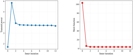
Figure 2 demonstrates that the inner-layer AO loop converges stably. The penalty merit function drops significantly in the first iteration due to the slack-augmented feasibility-restoration step, which moves the algorithm from an infeasible initialization to a feasible region. Consequently, the transmit power initially rises to satisfy the robust constraints and then decreases steadily alongside the merit function as the AO mechanism progressively removes redundant power expenditure.
Figure 2.
Inner-layer convergence of the transmit power and the penalty merit function.
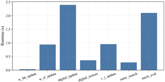
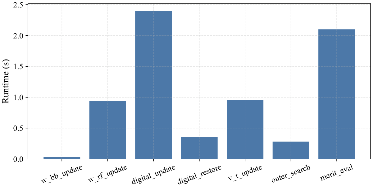
Figure 3 illustrates the computational characteristics of the implementation. Consistent with the theoretical analysis in Section 4.6, the exact convex surrogate solutions dominate the total runtime, followed by the analog discrete searches. The feasibility restoration is invoked only once. Overall, the proposed AO framework exhibits stable merit-descent behavior and remains computationally manageable, providing a reliable numerical foundation for the subsequent large-scale simulations.
Figure 3.
Runtime breakdown of the implemented AO framework.
5.3. Transmit Beampattern and Sensing Performance
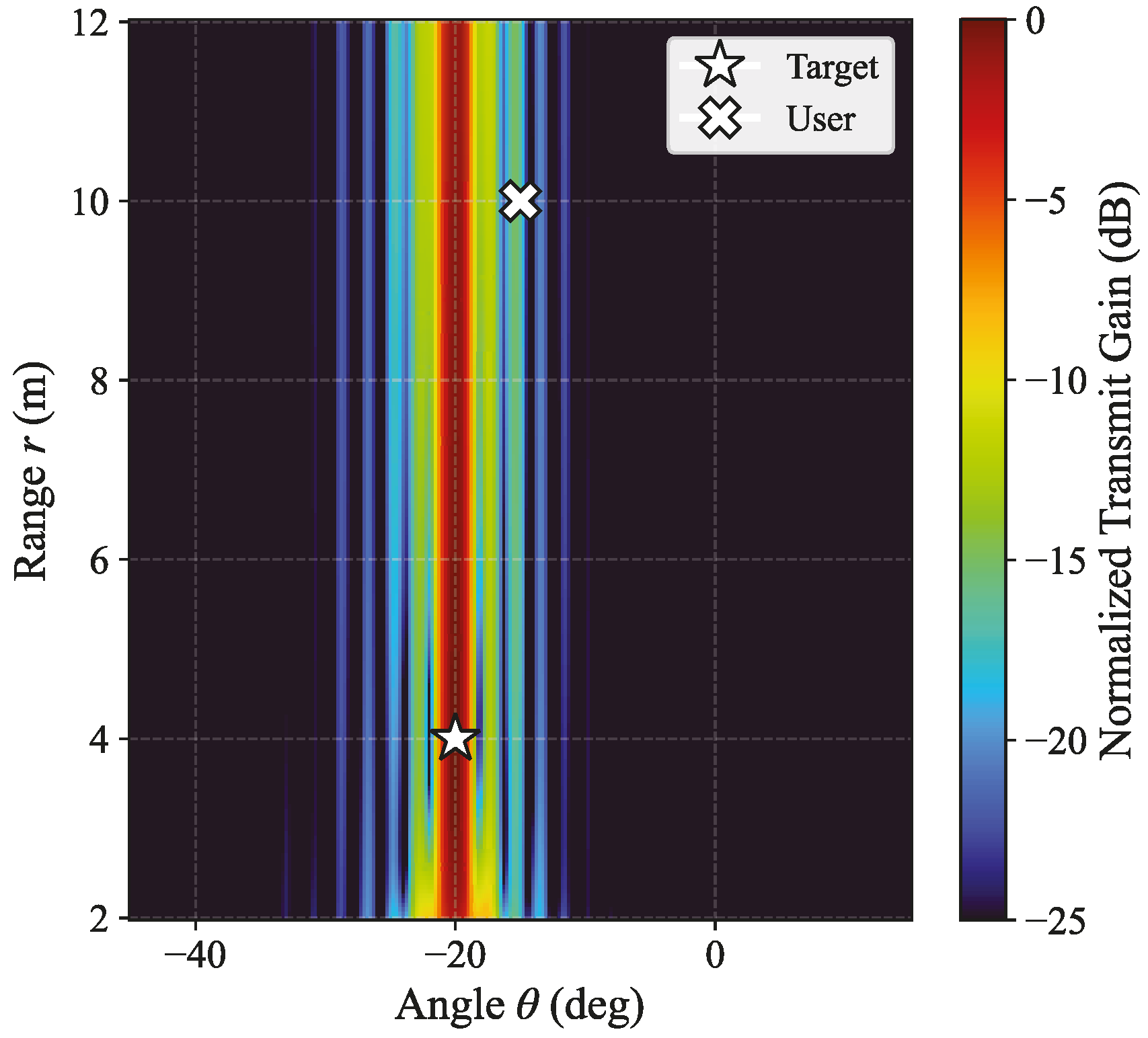
This subsection evaluates the spatial sensing capabilities of the optimized transmit covariance. We adopt a larger-aperture setting with , , , , and m. Since the target lies well inside the Rayleigh distance ( m), the transmit response depends jointly on range and angle.
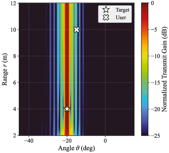
Figure 4 depicts the normalized 2D transmit illumination map. The optimized design concentrates the dominant sensing energy almost exactly at the desired target location . Furthermore, the beampattern explicitly reflects the near-field spherical-wave propagation, exhibiting a finite range-selective high-illumination region rather than remaining invariant with respect to distance.
Figure 4.
Normalized 2D near-field transmit beampattern of the sidelobe-constrained design.
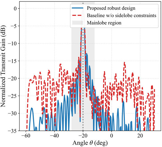
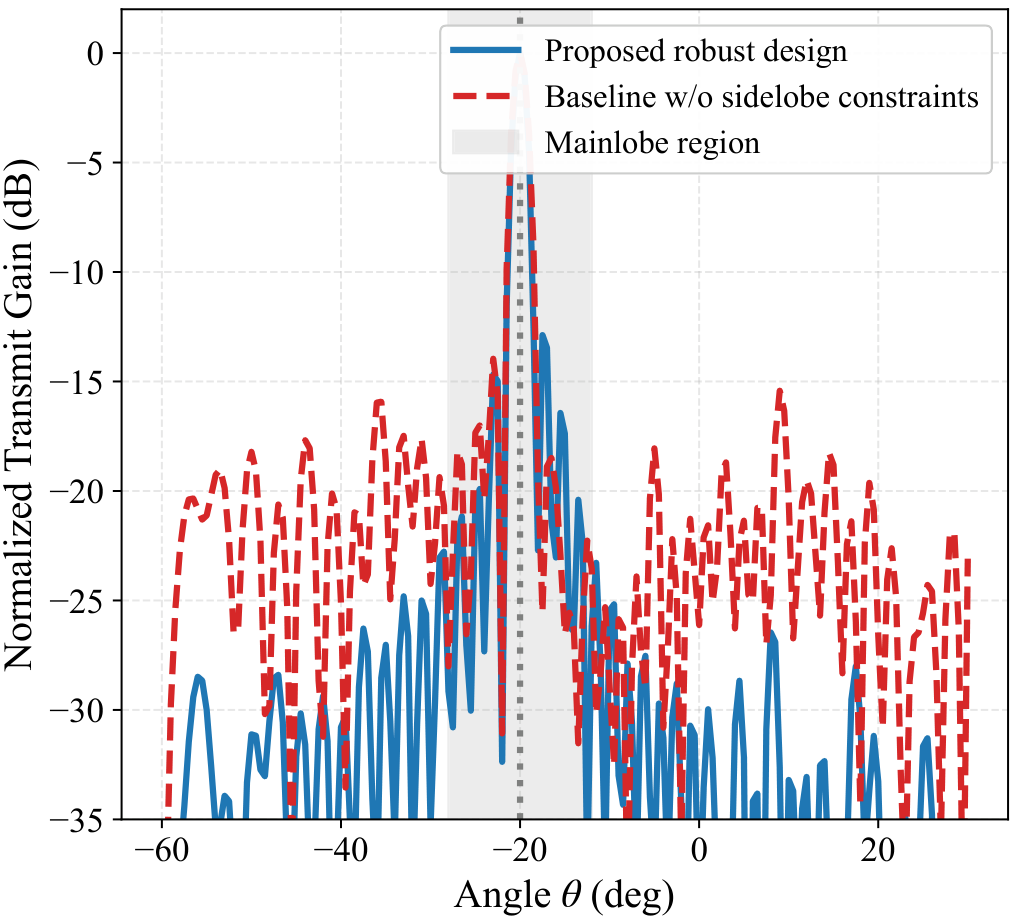
Figure 5 compares the angular cuts at the target range m with and without the sidelobe constraint. The constrained design preserves the mainlobe while substantially reducing energy leakage outside the guard region. Both the maximum and integrated sidelobe levels are significantly improved, demonstrating that the sidelobe-aware robust design effectively suppresses aggregate out-of-sector leakage, which is crucial for reducing unintended illumination toward hostile directions.
Figure 5.
Angular cut of the normalized beampattern at the target range with and without sidelobe suppression.
5.4. Robustness Against Uncertainties and Interference
This subsection validates the effectiveness of the deterministic robust reformulations against imperfect CSI, unknown interference, and target location errors. We adopt a reduced-scale setting with , , , and . The non-robust baseline is obtained by setting the corresponding uncertainty parameter to zero during optimization.
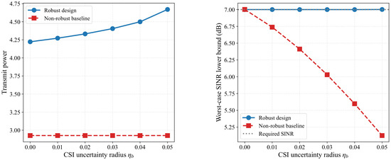
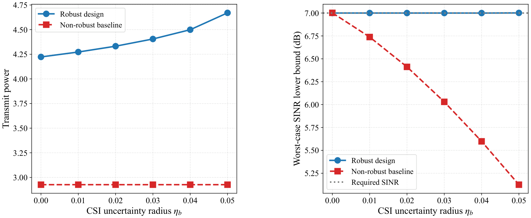
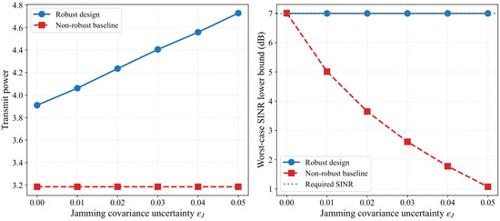
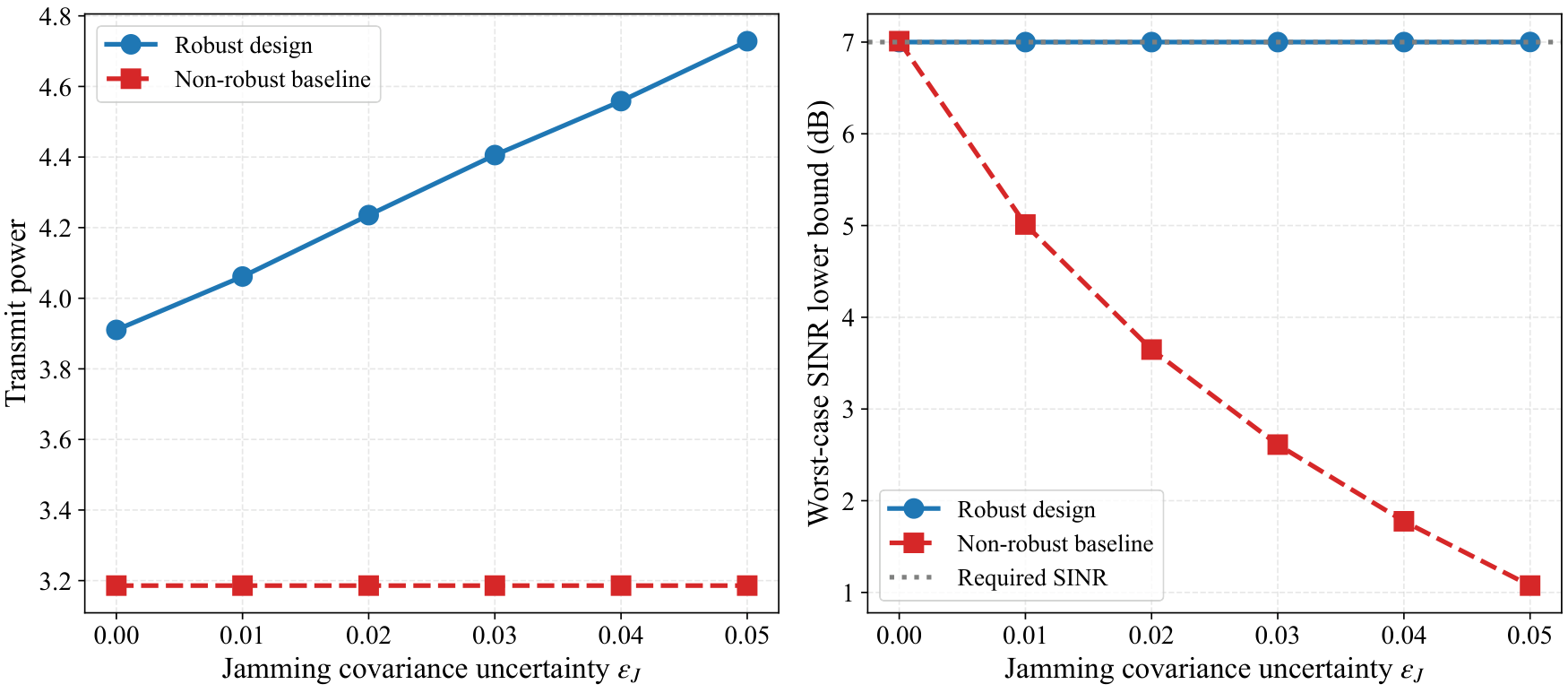
Figure 6 and Figure 7 evaluate the impact of CSI uncertainty () and interference covariance uncertainty (), respectively. In both cases, the robust design requires progressively more transmit power as the uncertainty radius increases. However, this apparent power penalty is necessary: while the robust design successfully maintains the guaranteed SINR lower bound at the prescribed 7 dB level over the entire uncertainty range, the non-robust baseline suffers severe SINR degradation, dropping to dB at and drastically to dB at . This confirms that explicitly modeling worst-case uncertainties is essential for sustaining communication reliability.
Figure 6.
Robustness against CSI uncertainty: (left) transmit power versus ; (right) guaranteed SINR lower bound versus .
Figure 7.
Robustness against interference covariance uncertainty: (left) transmit power versus ; (right) guaranteed SINR lower bound versus .
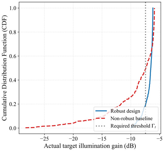
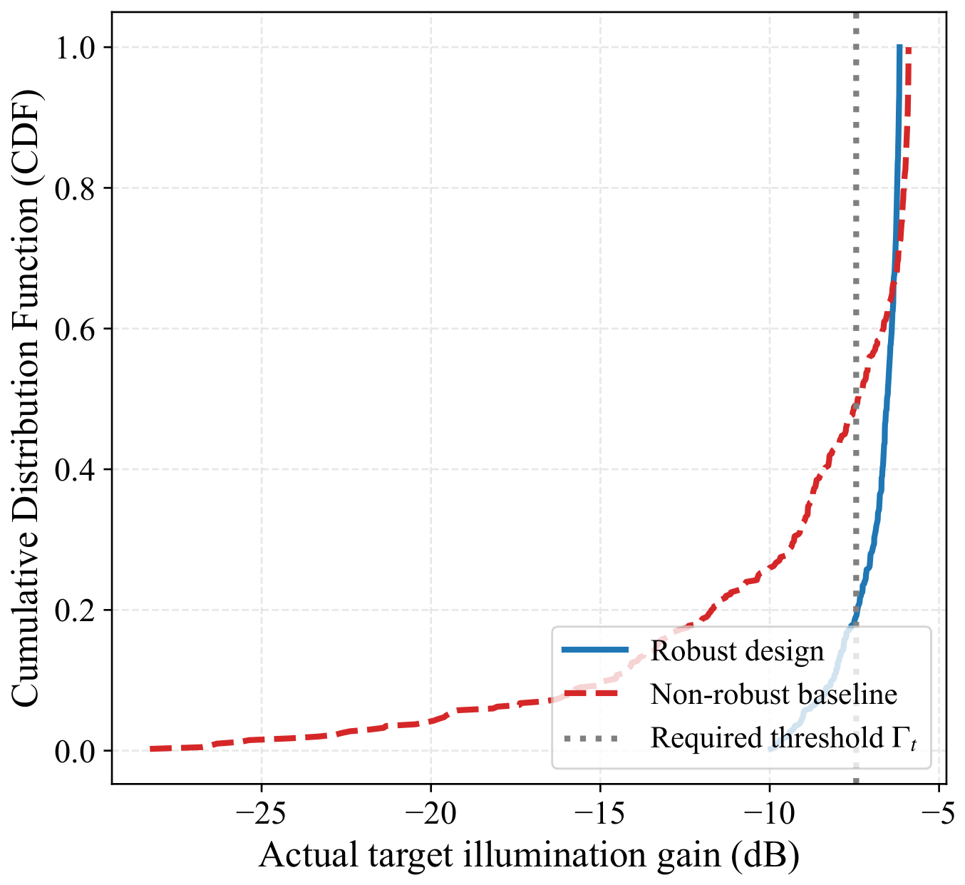
Figure 8 evaluates the sensing robustness under target location uncertainty over 400 random realizations. The robust design shifts the entire gain distribution to the right, reducing the empirical outage ratio from (non-robust) to . Although a residual outage remains—because the ellipsoidal relaxation provides a tractable surrogate rather than a strict absolute envelope for all extreme near-field phase wraps—the robust design significantly improves the 10th percentile gain by over 6 dB. This validates the practical effectiveness of the adopted deterministic robust approximation for sensing.
Figure 8.
Empirical CDF of the actual target gain under location uncertainty.
5.5. Comparison Among Subarray Architectures
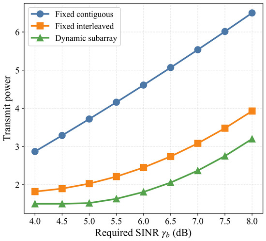
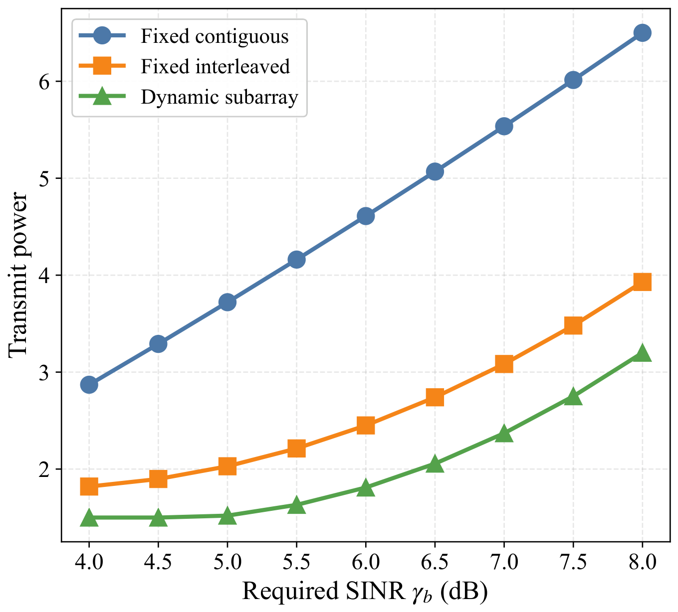
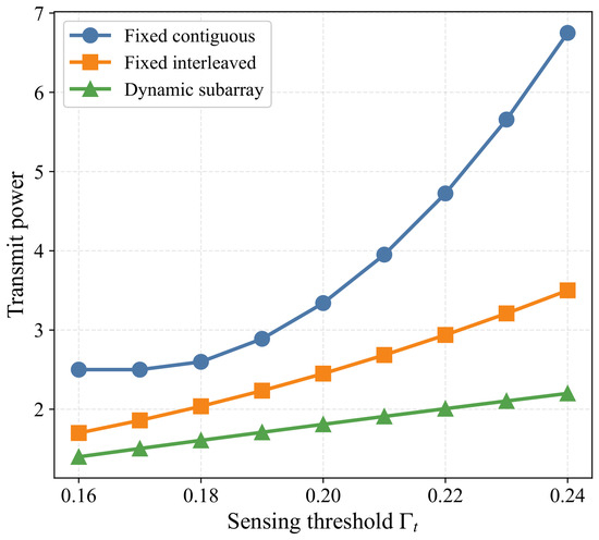
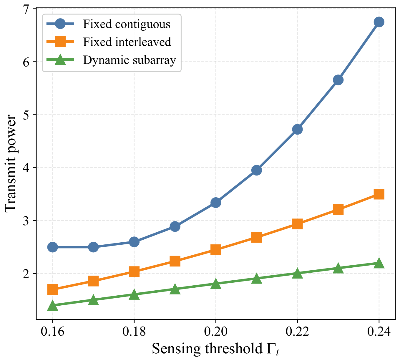
This subsection compares the proposed dynamic subarray against two standard fixed partially connected baselines: the fixed contiguous partition and the fixed interleaved partition. All schemes use the same hybrid transceiver model and AO updates; they differ only in whether the subarray topology is dynamically refined. The dynamic architecture is initialized from the interleaved partition.
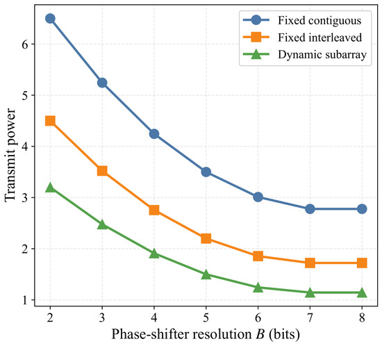
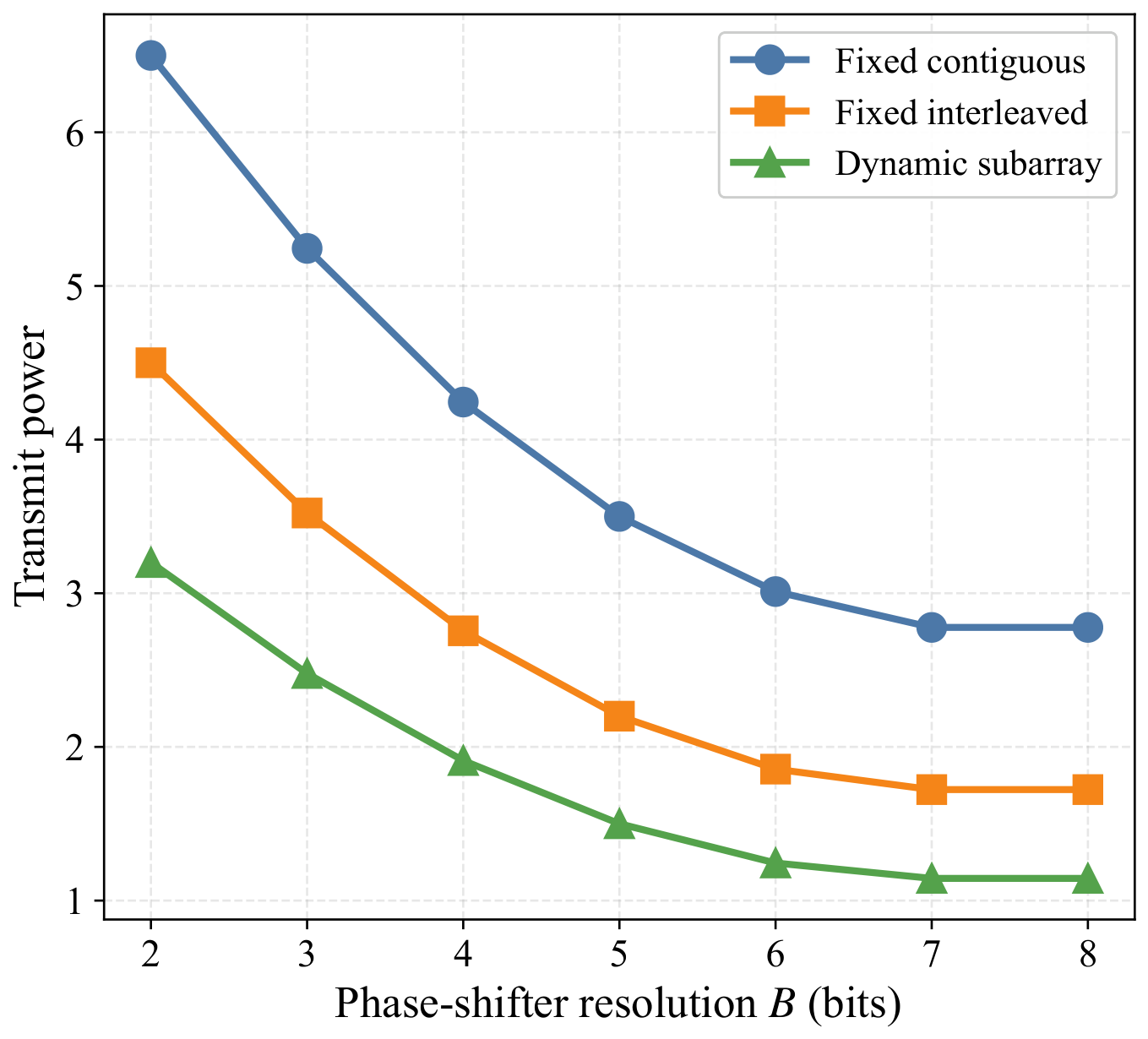
Figure 9, Figure 10 and Figure 11 evaluate the required transmit power across varying communication SINR targets (), sensing gain thresholds (), and phase-shifter resolutions (B), respectively. The results consistently demonstrate that the dynamic architecture requires the least transmit power across all configurations. For instance, at dB (Figure 9), the dynamic design saves and power compared to the fixed interleaved and contiguous structures, respectively. Similar prominent advantages are observed under stringent sensing requirements (Figure 10) and across low-to-high phase-shifter resolutions (Figure 11). These comprehensive sweeps confirm that dynamic antenna-to-RF-chain adaptation systematically provides a robust and unambiguous power efficiency gain over rigid subarray structures.
Figure 9.
Transmit power versus communication SINR requirements for different subarray architectures.
Figure 10.
Transmit power versus sensing-gain requirements for different subarray architectures.
Figure 11.
Transmit power versus phase-shifter resolutions for different subarray architectures.
5.6. Additional Robustness, Sensitivity, and Topology Benchmark Analyses
This subsection presents reduced-scale robustness and sensitivity analyses that characterize the practical behavior of the dynamic subarray architecture, its dependence on initialization, its degradation under hardware and channel mismatch, and its empirical distance to a small-scale topology benchmark. Unless otherwise stated, these reduced-scale analyses use , , , , and , so that repeated random trials and exhaustive topology enumeration remain reproducible.
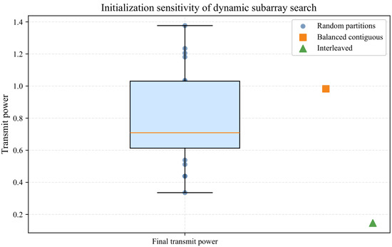
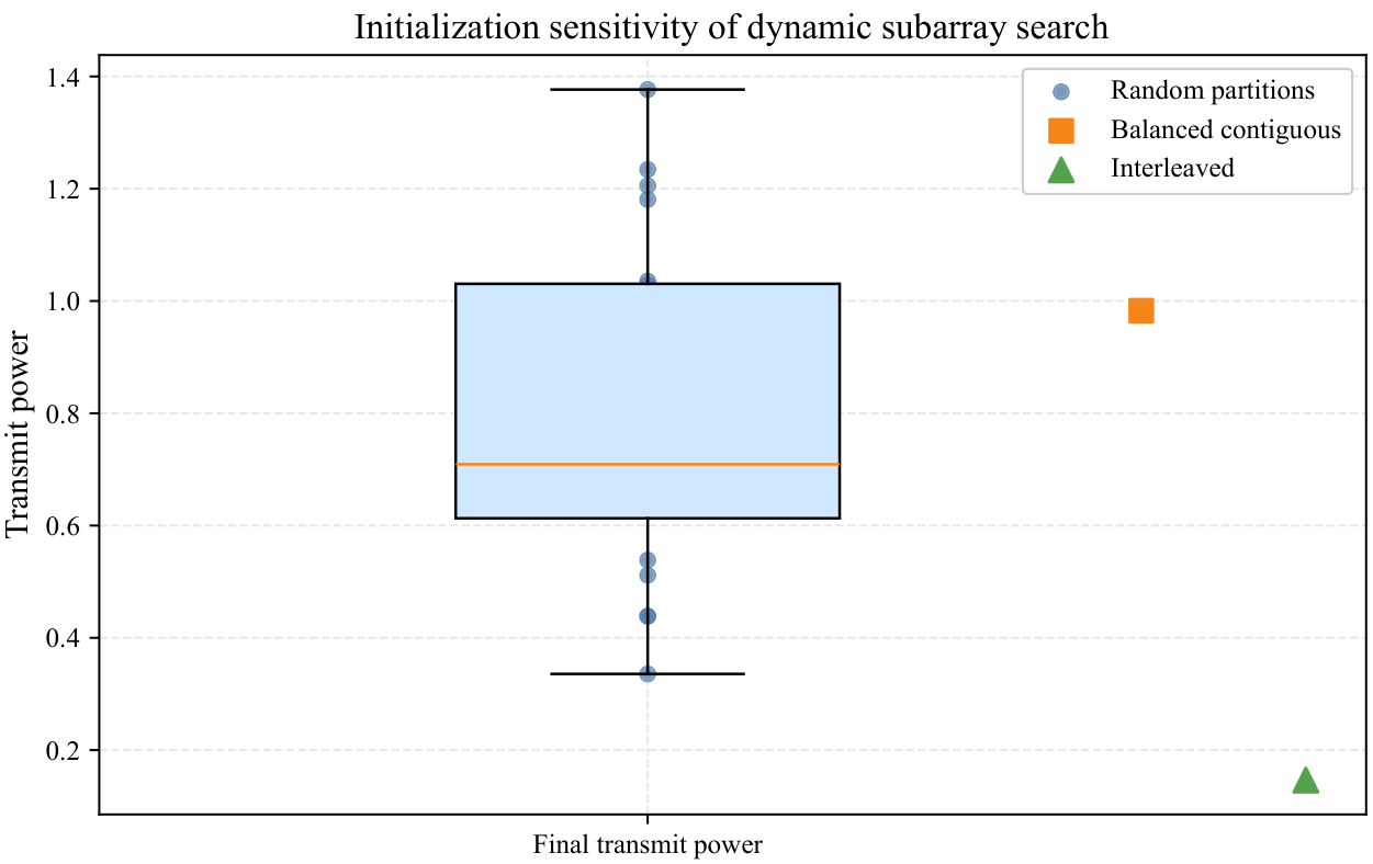
Figure 12 confirms that the one-antenna local search is initialization-sensitive. Across 20 random partitions, the final transmit power has a mean of , a standard deviation of , abest value of , and a worst value of . The balanced contiguous initialization converges to , about above the random mean, whereas the interleaved warm start converges to , about below the random mean. These observations support deterministic structured warm starts and, when runtime permits, multi-start random initialization. They also indicate that the dynamic subarray layer functions as a local topology refinement rather than a globally optimal topology solver.
Figure 12.
Initialization sensitivity of the dynamic subarray local search. The reduced-scale test compares a balanced contiguous partition, an interleaved warm start, and 20 random feasible partitions.
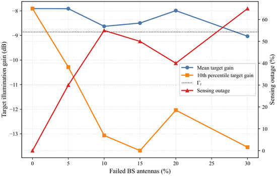
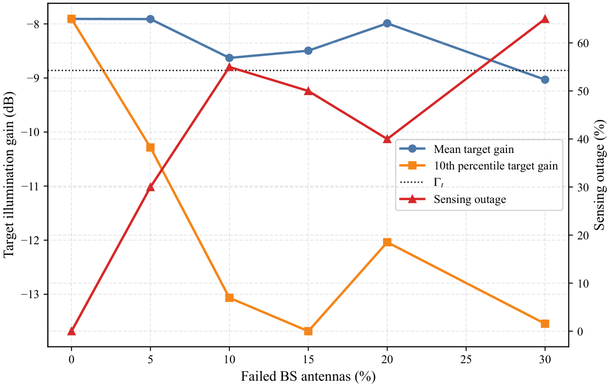
Figure 13 evaluates the achievable target illumination gain under partial BS antenna failures using a , , , instance. Without failures, the nominal target gain is dB, above the sensing threshold ( dB), and the communication SINR lower bound is dB. When only one antenna is disabled (), the mean target gain remains close to the nominal value, but the 10th-percentile gain drops to dB and the sensing outage reaches . With five disabled antennas (), the sensing outage increases to . Thus, the proposed design can absorb mild average degradation, but it cannot guarantee both communication and sensing performance once hardware failures remove too many effective spatial degrees of freedom or create unfavorable aperture holes.
Figure 13.
Target illumination under partial BS antenna element failures. For each failure fraction, 60 random failure masks are evaluated using the optimized transmit covariance after the failed antennas are disabled.
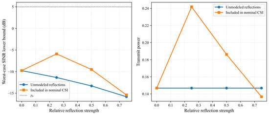
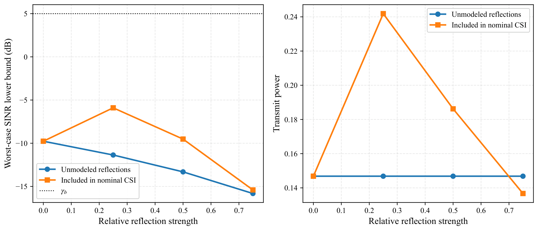
Figure 14 studies two additional near-field specular paths with relative strength from 0 to . When the reflections are not included in the nominal CSI, the worst-case SINR lower bound decreases by about dB at a relative strength of , indicating that strong unmodeled multipath can drive the actual channel outside the adopted CSI uncertainty envelope. When the same reflections are included in the nominal CSI, the algorithm can redesign the hybrid beamformers and may even exploit moderate reflected paths as additional spatial diversity. However, at the strongest tested reflection level, the SINR lower bound again degrades, showing that very strong multipath still requires timely channel re-estimation, a larger uncertainty radius, or additional RF/spatial degrees of freedom.
Figure 14.
Behavior under two strong near-field specular reflections. The unmodeled case optimizes the LoS-dominant nominal channel and evaluates the actual multipath channel; the modeled case includes the reflections in the nominal CSI before optimization.
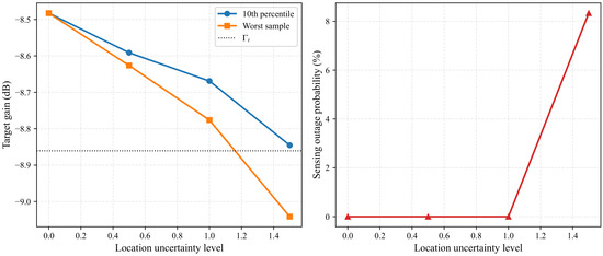
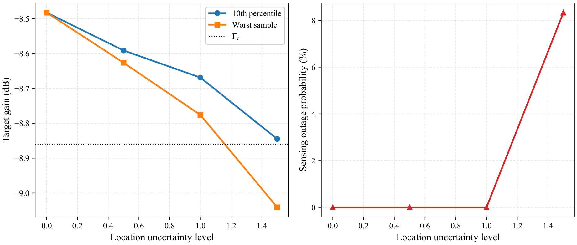
Figure 15 reports target-gain fluctuation metrics under increasing range-angle uncertainty. At uncertainty levels 0, , , and , the 10th-percentile target gains are , , , and dB, respectively, while the worst sampled gain at the largest uncertainty level is dB. The empirical outage probability remains zero up to level and increases to at level . These results complement the CDF in Figure 8 by showing variance, lower-tail degradation, and outage probability explicitly.
Figure 15.
Sensing-gain fluctuation under increasing target-location uncertainty. The figure reports lower-tail target gain and empirical outage probability over 300 random perturbations at each uncertainty level.
Table 1 further illustrates how rapidly varying interference statistics affect the robust design. In this reduced-SINR sensitivity analysis, the SINR lower bound remains above the dB requirement even when the actual covariance perturbation is twice the design radius, but the margin shrinks monotonically from dB to dB. This behavior is consistent with the role of : it provides a robustness margin only for covariance deviations covered by the chosen uncertainty set, and larger drift consumes the available SINR margin.
Table 1.
Covariance-drift sensitivity analysis for a reduced-SINR demonstration case with dB.
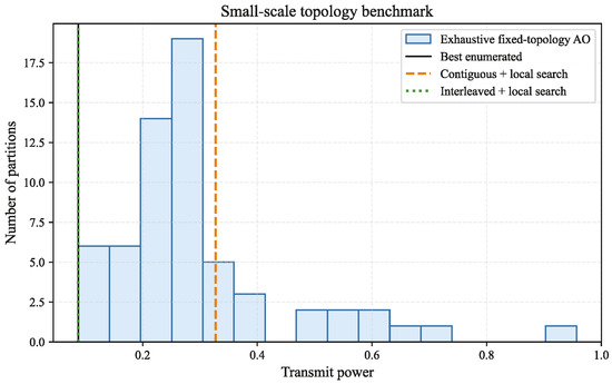
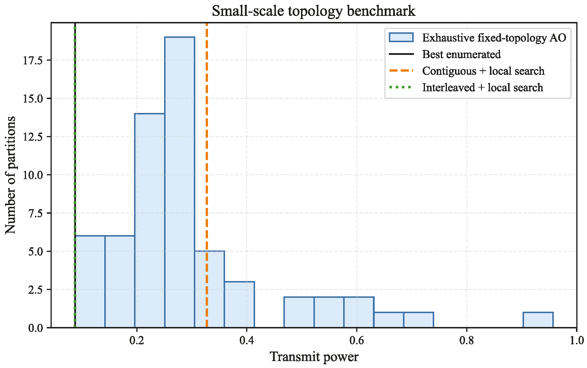
Figure 16 evaluates how close the local-search result can be to a small-scale exhaustive topology benchmark. Among 62 feasible non-empty partitions, the best enumerated power is . Starting from the interleaved partition and applying the local search yields the best enumerated value for the tested instance, whereas starting from the contiguous partition converges to , corresponding to a gap. Although this reduced-scale benchmark does not establish global optimality for the original large-scale mixed-integer robust problem, it indicates that the proposed local search can reach the best enumerated topology from a favorable warm start and also explains why poor initial partitions should be avoided or supplemented by multi-start search.
Figure 16.
Small-scale topology benchmark with and . All 62 non-empty antenna-to-RF-chain partitions are enumerated and optimized by the same inner AO routine.
Overall, the dynamic subarray architecture yields the largest power reductions when enough active antennas and RF-chain degrees of freedom remain, the interference covariance is updated on the same time scale as the environment, and the dominant propagation paths are captured by the nominal CSI or by the adopted uncertainty envelope. The formal guarantees do not apply, or can become overly conservative, when the uncertainty radius is smaller than the true mismatch, when covariance drift is faster than the update window, when too many antennas fail, when strong multipath components are unmodeled, or when the SINR and sensing thresholds exceed the spatial degrees of freedom available under finite-resolution phase shifters.
5.7. Comparison with Literature-Inspired Baselines
To demonstrate the practical significance of the proposed unified robust design, we compare it against three literature-inspired baselines adapted to our setting: (1) ISAC-HBF Baseline [16], a conventional non-robust ISAC scheme with a fixed contiguous subarray; (2) Robust-CSI ISAC Baseline [22], a dynamic subarray scheme robust to CSI errors but oblivious to interference and target uncertainties; and (3) Interference-Resilient Comm Baseline [24], a communication-centric scheme lacking sensing constraints.
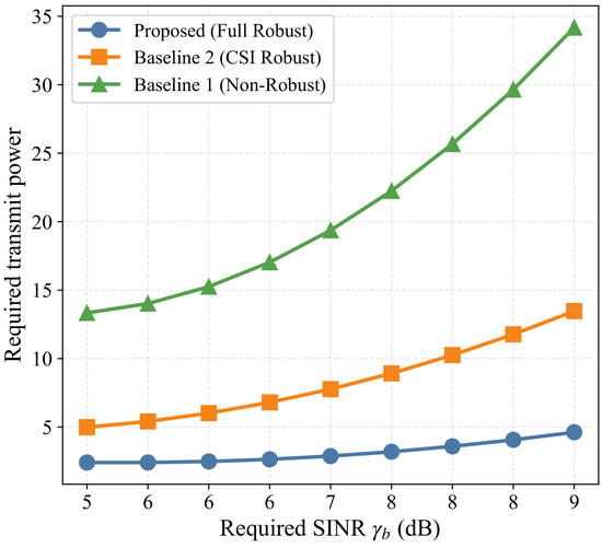
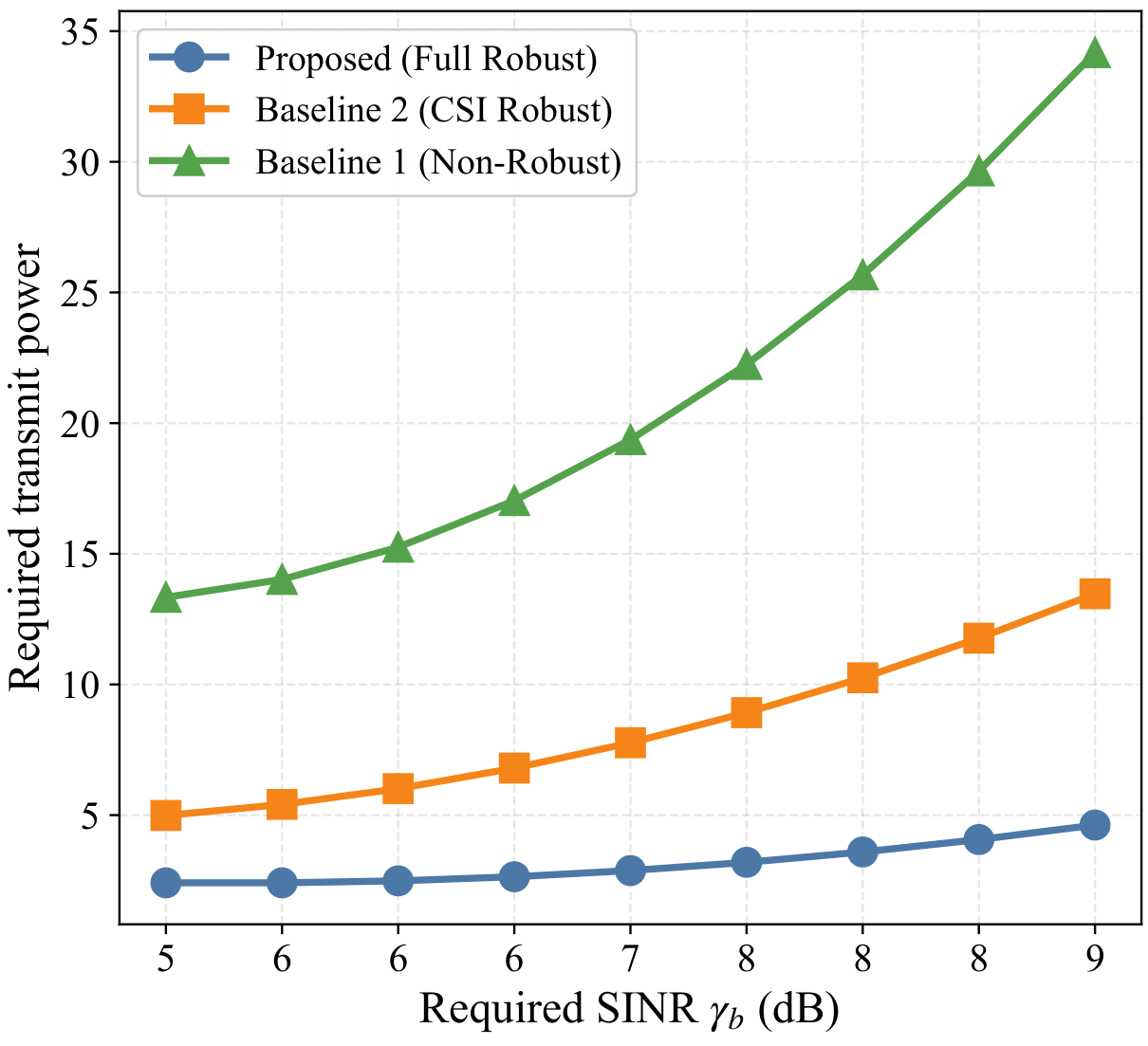
Figure 17 compares the required transmit power across different SINR targets under the actual uncertain environment (). The transmit power of all schemes is scaled to meet the actual worst-case SINR lower bound. Remarkably, the proposed fully robust scheme requires drastically less scaled power. For instance, at dB, it requires only units, whereas Baseline 2 and Baseline 1 require and , respectively. This counter-intuitive power saving stems from the architectural superiority of the dynamic subarray combined with exact spatial nulling of the interference subspace, demonstrating that non-robust methods suffer severe power penalties to satisfy actual reliability constraints.
Figure 17.
Required transmit power versus the required communication SINR for the proposed scheme and state-of-the-art baselines.
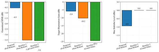
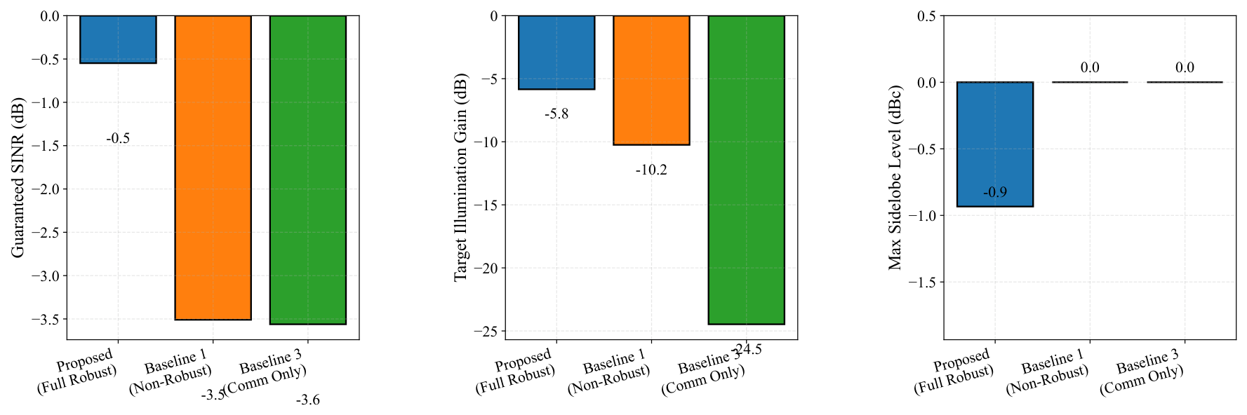
Figure 18 evaluates the multi-metric performance under an equal transmit power budget (). The baselines exhibit severe vulnerabilities: Baseline 3 completely fails at sensing (target gain dB, no sidelobe suppression), while Baseline 1 fails to provide reliable communication (guaranteed SINR drops to dB) and suffers degraded sensing gain ( dB) due to channel mismatch. In sharp contrast, the proposed scheme successfully balances all objectives, maintaining the highest guaranteed SINR ( dB), strong target gain ( dB), and effective sidelobe suppression ( dBc). These results conclusively demonstrate the necessity of the proposed framework in hostile electromagnetic environments.
Figure 18.
Multi-metric performance comparison under an equal transmit power budget.
6. Conclusions
This paper investigated robust hybrid beamforming and dynamic subarray design for near-field mmWave ISAC systems with imperfect CSI and unknown aggregate interference. We formulated a worst-case transmit-power minimization problem that jointly enforces a communication SINR requirement, target-oriented near-field illumination, sidelobe suppression, finite-resolution phase constraints, and dynamic antenna-to-RF-chain connectivity. To make the problem tractable, the spherical-wave nominal channel was combined with conservative CSI and covariance uncertainty envelopes, and the resulting semi-infinite constraints were converted into deterministic surrogate constraints. A two-layer AO framework was then developed: the inner layer updates the digital and phase-quantized hybrid beamformers, while the outer layer performs penalty-driven one-antenna local search over the dynamic subarray topology.
The simulations show three main findings. First, robust uncertainty modeling prevents severe reliability loss: under CSI and covariance uncertainty, the robust design preserves the prescribed SINR lower bound, whereas non-robust baselines suffer large degradation. Second, dynamic subarray adaptation reduces the required transmit power relative to fixed contiguous and interleaved architectures, especially when communication and sensing constraints compete for limited RF-chain degrees of freedom. Third, the additional robustness and sensitivity analyses clarify the method’s practical limits. The subarray local search is sensitive to initialization, but structured warm starts and multi-start search can substantially reduce this risk; partial antenna failures and unmodeled strong specular reflections can erode the sensing and communication margins; and covariance drift consumes the robustness margin unless the nominal covariance and radius are updated at a suitable time scale.
These findings are subject to the adopted conservative surrogate model. The proposed algorithm guarantees monotone descent of the fixed-penalty merit function, but it does not guarantee global optimality for the original mixed-integer semi-infinite robust problem. Future work should therefore consider tighter near-field structured uncertainty sets, online covariance tracking, failure-aware reconfiguration with explicit hardware diagnostics, and global or learning-assisted initialization strategies for large-scale dynamic subarray search.
Author Contributions
Conceptualization, D.N. and P.C.; methodology, D.N.; software, D.N.; validation, C.Z. and H.Y.; formal analysis, K.C.; investigation, K.C.; resources, X.F.; data curation, D.N.; writing—original draft preparation, D.N.; writing—review and editing, P.C. and X.F.; visualization, C.Z.; supervision, P.C. and X.F.; project administration, P.C. and X.F.; funding acquisition, P.C. and X.F. All authors have read and agreed to the published version of the manuscript.
Funding
This research was funded by the National Natural Science Foundation of China under Grant 61801112.
Data Availability Statement
The original contributions presented in this study are included in the article material. Further inquiries can be directed to the corresponding author.
Conflicts of Interest
The authors declare no conflicts of interest.
References
- Alkhateeb, A.; Ayach, O.E.; Leus, G.; Heath, R.W. Channel Estimation and Hybrid Precoding for Millimeter Wave Cellular Systems. IEEE J. Sel. Top. Signal Process. 2014, 8, 831–846. [Google Scholar] [CrossRef] [Scilit]
- Alkhateeb, A.; Leus, G.; Heath, R.W. Limited Feedback Hybrid Precoding for Multi-User Millimeter Wave Systems. IEEE Trans. Wirel. Commun. 2015, 14, 6481–6494. [Google Scholar] [CrossRef] [Scilit]
- Gao, X.; Dai, L.; Han, S.; I, C.L.; Heath, R.W. Energy-Efficient Hybrid Analog and Digital Precoding for mmWave MIMO Systems with Large Antenna Arrays. IEEE J. Sel. Areas Commun. 2016, 34, 998–1009. [Google Scholar]
- Wang, Z.; Li, M.; Liu, Q.; Swindlehurst, A.L. Hybrid Precoder and Combiner Design with Low-Resolution Phase Shifters in mmWave MIMO Systems. IEEE J. Sel. Top. Signal Process. 2018, 12, 256–269. [Google Scholar]
- Yuan, M.; Wang, H.; Yin, H.; He, D. Alternating Optimization Based Hybrid Transceiver Designs for Wideband Millimeter-Wave Massive Multiuser MIMO-OFDM Systems. IEEE Trans. Wirel. Commun. 2023, 22, 9201–9217. [Google Scholar]
- Ren, W.; Deng, J.; Cheng, X. MMSE Hybrid Beamforming for Multi-User Millimeter Wave MIMO Systems. IEEE Commun. Lett. 2023, 27, 3389–3393. [Google Scholar] [CrossRef] [Scilit]
- Elbir, A.M.; Papazafeiropoulos, A.K. Hybrid Precoding for Multiuser Millimeter Wave Massive MIMO Systems: A Deep Learning Approach. IEEE Trans. Veh. Technol. 2020, 69, 552–563. [Google Scholar]
- Yu, H.; Tuan, H.D.; Dutkiewicz, E.; Poor, H.V.; Hanzo, L. Regularized Zero-Forcing Aided Hybrid Beamforming for Millimeter-Wave Multiuser MIMO Systems. IEEE Trans. Wirel. Commun. 2023, 22, 3280–3295. [Google Scholar] [CrossRef] [Scilit]
- Banerjee, B.; Elliott, R.C.; Krzymien, W.A.; Medra, M. Hybrid Beamforming for mmWave Massive MIMO Systems Using Conditional Generative Adversarial Networks. IEEE Trans. Veh. Technol. 2024, 73, 15803–15808. [Google Scholar] [CrossRef] [Scilit]
- Lee, J.; Chung, H.; Cho, Y.; Kim, S.; Hong, S. Near-Field Channel Estimation for XL-RIS Assisted Multi-User XL-MIMO Systems: Hybrid Beamforming Architectures. IEEE Trans. Commun. 2025, 73, 1560–1574. [Google Scholar] [CrossRef] [Scilit]
- Wu, Z.; Dai, L. The Manifestation of Spatial Wideband Effect in Circular Array: From Beam Split to Beam Defocus. IEEE Trans. Commun. 2024, 72, 3064–3078. [Google Scholar] [CrossRef] [Scilit]
- Deng, W.; Li, M.; Zhao, M.M.; Zhao, M.J.; Simeone, O. CSI Transfer from Sub-6G to mmWave: Reduced-Overhead Multi-User Hybrid Beamforming. IEEE J. Sel. Areas Commun. 2025, 43, 973–987. [Google Scholar]
- Liu, F.; Masouros, C.; Petropulu, A.P.; Griffiths, H.; Hanzo, L. Joint Radar and Communication Design: Applications, State-of-the-Art, and the Road Ahead. IEEE Trans. Commun. 2020, 68, 3834–3862. [Google Scholar]
- Barneto, C.B.; Riihonen, T.; Liyanaarachchi, S.D.; Heino, M.; Gonzalez-Prelcic, N.; Valkama, M. Beamformer Design and Optimization for Joint Communication and Full-Duplex Sensing at mm-Waves. IEEE Trans. Commun. 2022, 70, 8298–8312. [Google Scholar] [CrossRef] [Scilit]
- Singh, J.; Naveen, B.; Srivastava, S.; Jagannatham, A.K.; Hanzo, L. Pareto Optimal Hybrid Beamforming for Short-Packet Millimeter-Wave Integrated Sensing and Communication. IEEE Trans. Commun. 2025, 73, 4570–4585. [Google Scholar]
- Qi, C.; Ci, W.; Zhang, J.; You, X. Hybrid Beamforming for Millimeter Wave MIMO Integrated Sensing and Communications. IEEE Commun. Lett. 2022, 26, 1136–1140. [Google Scholar] [CrossRef] [Scilit]
- Gao, Z.; Wan, Z.; Zheng, D.; Tan, S.; Masouros, C.; Ng, D.W.K.; Chen, S. Integrated Sensing and Communication with mmWave Massive MIMO: A Compressed Sampling Perspective. IEEE Trans. Wirel. Commun. 2023, 22, 1745–1762. [Google Scholar] [CrossRef] [Scilit]
- Guo, J.; Qi, C. Hybrid Beamforming for Wideband Millimeter Wave MIMO Integrated Sensing and Communications. IEEE Commun. Lett. 2025, 29, 462–466. [Google Scholar]
- He, D.; Liu, Y.; Yuan, M.; Wang, H.; Yin, H.; Niyato, D.; Peng, M. Hybrid Beamforming for mmWave Integrated Sensing and Communication with Multi-Static Cooperative Localization. IEEE Trans. Wirel. Commun. 2026, 25, 771–786. [Google Scholar]
- Chen, Z.; Chen, P.; Guo, Z.; Zhang, Y.; Wang, X. A RIS-Based Vehicle DOA Estimation Method with Integrated Sensing and Communication System. IEEE Trans. Intell. Transp. Syst. 2024, 25, 5554–5566. [Google Scholar] [CrossRef] [Scilit]
- Wang, D.; Bazzi, A.; Chafii, M. DRIP: A Versatile Family of Space-Time ISAC Discrete-Time Sequences. IEEE J. Sel. Areas Inf. Theory 2026, 7, 205–220. [Google Scholar] [CrossRef] [Scilit]
- Li, S.; Dong, H.; Shan, C.; Fang, X.; Wu, W.; Li, Z. Secure Hybrid Beamforming Design for mmWave Integrated Sensing and Communication Systems. IEEE Trans. Veh. Technol. 2025, 74, 10622–10638. [Google Scholar] [CrossRef] [Scilit]
- Priyadarshani, R.; Park, K.H.; Ata, Y.; Alouini, M.S. Jamming Intrusions in Extreme Bandwidth Communication: A Comprehensive Overview. IEEE Open J. Commun. Soc. 2025, 6, 7125–7149. [Google Scholar] [CrossRef] [Scilit]
- Qi, X.; Peng, M.; Zhang, H.; Kong, X. Anti-Jamming Hybrid Beamforming Design for Millimeter-Wave Massive MIMO Systems. IEEE Trans. Wirel. Commun. 2024, 23, 9160–9172. [Google Scholar] [CrossRef] [Scilit]
- Wang, Z.; Chen, P.; Wang, Z.; Luo, T.; Zhang, Y. A Pragmatic Anti-Interference Algorithm for Hybrid Beamforming in Millimeter Wave MIMO Systems. IEEE Commun. Lett. 2024, 28, 2613–2617. [Google Scholar] [CrossRef] [Scilit]
- Lin, Z.; Lin, M.; Champagne, B.; Zhu, W.P.; Al-Dhahir, N. Secrecy-Energy Efficient Hybrid Beamforming for Satellite-Terrestrial Integrated Networks. IEEE Trans. Commun. 2021, 69, 6345–6360. [Google Scholar]
- Wu, D.; Shen, T.; Shu, F.; Wu, Y.; Zhu, L.; Feng, S.; Huang, M.; Wang, J. Secure Hybrid Analog and Digital Beamforming for mmWave XR Communications with Mixed-DAC. IEEE J. Sel. Top. Signal Process. 2023, 17, 995–1006. [Google Scholar] [CrossRef] [Scilit]
- Dong, H.; Fang, X.; Zhao, J.; Sha, X.; Li, Z. Signal Domain Multicomponent-Based Secure Hybrid Precoding for mmWave Systems. IEEE Trans. Wirel. Commun. 2025, 24, 51–67. [Google Scholar] [CrossRef] [Scilit]
- Chen, W.; Liu, C.; Wang, W.; Peng, M.; Zhang, W. Adaptive Hybrid Beamforming for UAV mmWave Communications Against Asymmetric Jitter. IEEE Trans. Wirel. Commun. 2024, 23, 9432–9445. [Google Scholar] [CrossRef] [Scilit]
- Luo, T.; Chen, P.; Cao, Z.; Zheng, L.; Wang, Z. URGLQ: An Efficient Covariance Matrix Reconstruction Method for Robust Adaptive Beamforming. IEEE Trans. Aerosp. Electron. Syst. 2023, 59, 5634–5645. [Google Scholar] [CrossRef] [Scilit]
- Ci, W.; Qi, C.; You, X. Hybrid Beamforming Design for Covert mmWave MIMO with Finite-Resolution DACs. IEEE J. Sel. Areas Commun. 2025, 43, 752–764. [Google Scholar]
- Qiao, J.; Zhang, C.; Dong, A.; Bian, J.; Alouini, M.S. Securing Intelligent Reflecting Surface Assisted Terahertz Systems. IEEE Trans. Veh. Technol. 2022, 71, 8519–8533. [Google Scholar] [CrossRef] [Scilit]
- Han, M.; Du, J.; Zhang, Y.; Chen, Y.; Li, X.; Rabie, K.M.; Kara, F. Hybrid Beamforming with Sub-Connected Structure for MmWave Massive Multi-User MIMO Relay Systems. IEEE Trans. Green Commun. Netw. 2023, 7, 772–786. [Google Scholar]
- Qi, C.; Hu, J.; Du, Y.; Nallanathan, A. Multiuser Beamforming for Partially-Connected Millimeter Wave Massive MIMO. IEEE Trans. Veh. Technol. 2024, 73, 5977–5981. [Google Scholar] [CrossRef] [Scilit]
- Gao, H.; Liu, D.; Zhang, Z. Energy Efficiency Maximization for Partially-Connected Hybrid Beamforming Architecture with Low-Resolution DACs. IEEE Trans. Commun. 2024, 72, 5765–5780. [Google Scholar]
- Zhang, D.; Wang, Y.; Li, X.; Xiang, W. Hybridly Connected Structure for Hybrid Beamforming in mmWave Massive MIMO Systems. IEEE Trans. Commun. 2018, 66, 662–674. [Google Scholar]
- Jin, X.; Lv, T.; Ni, W.; Lin, Z.; Zhu, Q.; Hossain, E.; Poor, H.V. A Reconfigurable Subarray Architecture and Hybrid Beamforming for Millimeter-Wave Dual-Function-Radar-Communication Systems. IEEE Trans. Wirel. Commun. 2024, 23, 12594–12607. [Google Scholar] [CrossRef] [Scilit]
- Hu, Y.; Qian, H.; Kang, K.; Luo, X.; Zhu, H. Joint Precoding Design for Sub-Connected Hybrid Beamforming System. IEEE Trans. Wirel. Commun. 2024, 23, 1199–1212. [Google Scholar]

Disclaimer/Publisher’s Note: The statements, opinions and data contained in all publications are solely those of the individual author(s) and contributor(s) and not of MDPI and/or the editor(s). MDPI and/or the editor(s) disclaim responsibility for any injury to people or property resulting from any ideas, methods, instructions or products referred to in the content. |
© 2026 by the authors. Licensee MDPI, Basel, Switzerland. This article is an open access article distributed under the terms and conditions of the Creative Commons Attribution (CC BY) license.